CN1466433A - Endoscopic suction-irrigation instrument for surgery - Google Patents
Endoscopic suction-irrigation instrument for surgery Download PDFInfo
- Publication number
- CN1466433A CN1466433A CNA018162096A CN01816209A CN1466433A CN 1466433 A CN1466433 A CN 1466433A CN A018162096 A CNA018162096 A CN A018162096A CN 01816209 A CN01816209 A CN 01816209A CN 1466433 A CN1466433 A CN 1466433A
- Authority
- CN
- China
- Prior art keywords
- sheath
- handle
- surgery
- fluid
- endoscopic instrument
- Prior art date
- Legal status (The legal status is an assumption and is not a legal conclusion. Google has not performed a legal analysis and makes no representation as to the accuracy of the status listed.)
- Pending
Links
Images


Classifications
-
- A—HUMAN NECESSITIES
- A61—MEDICAL OR VETERINARY SCIENCE; HYGIENE
- A61B—DIAGNOSIS; SURGERY; IDENTIFICATION
- A61B1/00—Instruments for performing medical examinations of the interior of cavities or tubes of the body by visual or photographical inspection, e.g. endoscopes; Illuminating arrangements therefor
- A61B1/12—Instruments for performing medical examinations of the interior of cavities or tubes of the body by visual or photographical inspection, e.g. endoscopes; Illuminating arrangements therefor with cooling or rinsing arrangements
-
- A—HUMAN NECESSITIES
- A61—MEDICAL OR VETERINARY SCIENCE; HYGIENE
- A61B—DIAGNOSIS; SURGERY; IDENTIFICATION
- A61B1/00—Instruments for performing medical examinations of the interior of cavities or tubes of the body by visual or photographical inspection, e.g. endoscopes; Illuminating arrangements therefor
- A61B1/00147—Holding or positioning arrangements
-
- A—HUMAN NECESSITIES
- A61—MEDICAL OR VETERINARY SCIENCE; HYGIENE
- A61B—DIAGNOSIS; SURGERY; IDENTIFICATION
- A61B1/00—Instruments for performing medical examinations of the interior of cavities or tubes of the body by visual or photographical inspection, e.g. endoscopes; Illuminating arrangements therefor
- A61B1/012—Instruments for performing medical examinations of the interior of cavities or tubes of the body by visual or photographical inspection, e.g. endoscopes; Illuminating arrangements therefor characterised by internal passages or accessories therefor
- A61B1/015—Control of fluid supply or evacuation
-
- A—HUMAN NECESSITIES
- A61—MEDICAL OR VETERINARY SCIENCE; HYGIENE
- A61B—DIAGNOSIS; SURGERY; IDENTIFICATION
- A61B17/00—Surgical instruments, devices or methods, e.g. tourniquets
- A61B17/24—Surgical instruments, devices or methods, e.g. tourniquets for use in the oral cavity, larynx, bronchial passages or nose; Tongue scrapers
-
- A—HUMAN NECESSITIES
- A61—MEDICAL OR VETERINARY SCIENCE; HYGIENE
- A61M—DEVICES FOR INTRODUCING MEDIA INTO, OR ONTO, THE BODY; DEVICES FOR TRANSDUCING BODY MEDIA OR FOR TAKING MEDIA FROM THE BODY; DEVICES FOR PRODUCING OR ENDING SLEEP OR STUPOR
- A61M1/00—Suction or pumping devices for medical purposes; Devices for carrying-off, for treatment of, or for carrying-over, body-liquids; Drainage systems
- A61M1/71—Suction drainage systems
- A61M1/77—Suction-irrigation systems
- A61M1/774—Handpieces specially adapted for providing suction as well as irrigation, either simultaneously or independently
-
- A—HUMAN NECESSITIES
- A61—MEDICAL OR VETERINARY SCIENCE; HYGIENE
- A61B—DIAGNOSIS; SURGERY; IDENTIFICATION
- A61B1/00—Instruments for performing medical examinations of the interior of cavities or tubes of the body by visual or photographical inspection, e.g. endoscopes; Illuminating arrangements therefor
- A61B1/233—Instruments for performing medical examinations of the interior of cavities or tubes of the body by visual or photographical inspection, e.g. endoscopes; Illuminating arrangements therefor for the nose, i.e. nasoscopes, e.g. testing of patency of Eustachian tubes
-
- A—HUMAN NECESSITIES
- A61—MEDICAL OR VETERINARY SCIENCE; HYGIENE
- A61B—DIAGNOSIS; SURGERY; IDENTIFICATION
- A61B17/00—Surgical instruments, devices or methods, e.g. tourniquets
- A61B17/32—Surgical cutting instruments
- A61B17/320016—Endoscopic cutting instruments, e.g. arthroscopes, resectoscopes
- A61B17/32002—Endoscopic cutting instruments, e.g. arthroscopes, resectoscopes with continuously rotating, oscillating or reciprocating cutting instruments
-
- A—HUMAN NECESSITIES
- A61—MEDICAL OR VETERINARY SCIENCE; HYGIENE
- A61M—DEVICES FOR INTRODUCING MEDIA INTO, OR ONTO, THE BODY; DEVICES FOR TRANSDUCING BODY MEDIA OR FOR TAKING MEDIA FROM THE BODY; DEVICES FOR PRODUCING OR ENDING SLEEP OR STUPOR
- A61M1/00—Suction or pumping devices for medical purposes; Devices for carrying-off, for treatment of, or for carrying-over, body-liquids; Drainage systems
- A61M1/71—Suction drainage systems
- A61M1/77—Suction-irrigation systems
- A61M1/772—Suction-irrigation systems operating alternately
Abstract
An ergonomically superior endoscopic suction-irrigation instrument for surgery comprises a telescope sheath (12) connected at an adjustable angle, preferably approximately 30 DEG , to a vertically elongated handle (16) having thumb-operated irrigation and suction valves (62, 64) and a hook (86) for supporting the handle from the surgeon's hand when the surgeon's grip on the handle is loosened. The instrument is especially suited for sinus surgery.
Description
Technical field
The present invention relates generally to surgical operation, specifically, relates to the improvement that is used in the apparatus that surgical operation (for example, sinus tract surgery) is used for aspirating, wash or both have both at the same time.
Background technology
The sinus tract surgery carries out by means of endoscope usually.The nostril that endoscope is inserted patient makes the surgeon be connected to the enlarged image of observing operative region on the monitor of the video camera that links to each other with endoscope one.Nose/sinus tract surgery carries out in a narrow and blood vessel gathers the space.Therefore, in operation process, there are blood and operating fragment to be splashed in the endoscope.For making operative region that best developing be arranged, keeping endoscope's lens to avoid blood is important with the operation fragment.In general, this by flushing endoscope lens or shift out the manual cleaning of endoscope-use from the nostril and finish.
Patient is under the general anesthesia and in supine position usually.Telescope is inserted the nostril and operation is positioned near the operative region its far-end.For the power that overcomes organizational structure and the endoscope's adnexa effect position with control endoscope, the surgeon refers to press from both sides with one and handles endoscope usually, and above-mentioned endoscope adnexa comprises, video camera head and cable, optical fiber light carrier and syringe pipe.The method that has found that this manipulation endoscope can cause fatigue, particularly in long operation process.
Another problem that traditional endoscope's sinus tract surgery runs into is the work space that blocks.Usually the method for clamping endoscope can limit other apparatus of operation, the work space around scope.During space around syringe pipe and/or bulky hands account for the nostril inlet, more increase this burden.
Existing pump drives rinse-system and has the foot operation control.Different controllers is handled in the position of (or she) because the doctor must move him, so, in surgical procedure, these controllers are placed in other foot operating equipment (such as, electrosurgery unit and electric cutting device) doctor is divert one's attention.These devices also are not easy to set up, and enough amount of liquid and hydraulic pressure can not be provided usually.
The objective of the invention is to be devoted to the problems referred to above, and catalogue of the present invention provide a good rinse-system that meets human engineering that is used for sinus tract surgery and other surgical operation that need wash and/or aspirate.
Summary of the invention
Comprise a tubular sheath along the extension of sheath axis according to of the present invention one preferable endoscopic instrument, sheath has one and admits telescopical inner passage, the inner passage admits opening to extend to far-end from the telescope of near-end, and the aperture that is used to connect suction and clean-up line; One has the hands handle of the outer surface that hands can grip; One suction valve in handle, this suction valve is connected with aspiration line, and the operation valve can provide the connection of described aperture and aspiration line; One flushing valve in handle, this flushing valve is connected with clean-up line, and the operation valve can provide the connection of described aperture and clean-up line; Manual operation controller on the handle is used for selectively opening suction and flushing valve; And a joint, it is connected to handle on the sheath along the length of the sheath between proximal openings and the far-end in the position in the middle rigidly; Wherein, handle is along handle axis elongation and favour sheath.Preferably, joint can be adjusted the angle between handle and the sheath.Sheath is locked on the joint releasedly, and sheath can rotate around the sheath axis when discharging.The telescopical appropriate location of that the turnability of sheath is convenient to tilt or side-looking.
As reading in conjunction with the accompanying drawings, then from following detailed description, can understand other purpose of the present invention, details and advantage.
Description of drawings
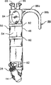
Fig. 1 is the axonometric chart according to the decomposition of an endoscopic instrument of a preferred embodiment of the present invention, and the assembly of telescope and telescope sheath and handle and suction valve is shown;
Fig. 2 is the right side view of the assembly of one handle and valve;
Fig. 3 is the left side view of the assembly of one handle and valve;
Fig. 4 is the front view of the assembly of one handle and valve;
Fig. 5 is the axonometric chart of the assembly of one handle and valve;
Fig. 6 is the plan view from above of the assembly of one handle and valve;
Fig. 7 is the face upwarding view of the assembly of one handle and valve;
Fig. 8 is a partial section, the fluidic connection between the assembly that handle and valve be shown and telescope sheath;
Fig. 9 is the decomposition view in a part of cross section, and telescope sheath and telescope sheath receptor are shown;
Figure 10 is a partial section, and the details that concerns between the inside of telescope sheath and the telescope end is shown; And
Figure 11 is the vertical cross-section of one handle, and the operation of flushing valve is shown.
The specific embodiment
As shown in Figure 1, apparatus 10 comprises a telescope sheath, and it is enclosed within one and is connected on the pipe joint 14 of lower end of elongate handgrip 16.
Telescope sheath 12 comprises the pipe 18 of an elongated and hollow, and this Guan Zaiqi end 20 has an opening.Sheath has a sleeve 22 that has an opening 24 at its near-end, and telescope can insert opening 24.The telescope that is used for this apparatus generally comprises an eyepiece 27, or a miniature TV camera (not shown).Eyepiece or video camera are connected to the near-end of axle 25, be furnished with one group of lens combination in the axle, the enlarged image that is used for adjoining the confined surgical areas of telescope end end focuses on an eyepiece or the miniature TV camera, when apparatus has been assembled fully, operative region will be positioned at the position of the end 20 of pipe 18.Optical fiber light carrier is arranged in the axle usually to illuminate confined surgical areas.
Telescope has an outthrust 31, and it cooperates with the locking appropriate location of telescope in sheath 12 with the sub-(not shown) of holding up in opening 24.(just below sleeve 22) has a nut 26 near the proximal end of sheath 12, and nut is rotatable but be suppressed along sheath and move axially.Sheath is removed in screw thread 28 engagements on nut and the pipe joint 14 to allow for replacing.Sheath axis around itself in pipe joint 14 is rotatable, and is locked on the turned position that requires arbitrarily by nut 26.Therefore, in order to observe zone, can be directed to the angle of any requirement with being locked in side-looking telescope in the sheath with respect to telescope axis one side.
As Fig. 1, shown in 8,9, under nut, a conical component 30 is arranged on the sheath, and conical component comprises axially spaced up and down two frustum part 30a and 30b.Conical component 30 is with fluid-tight relation and O shape ring 31a that is used as sealing member and 31b engagement.O shape ring is positioned at the annular groove of the bellmouth 33 that extends through pipe joint 14.Slit 32 is positioned at the narrow of the sheath between part 30a and 30b, it provides the inside of sheath 12 and the fluid that extends through between the fluid passage 35 of an adapter 34 is communicated with, this adapter is threaded in as shown in Figure 8 the pipe joint wall, and be equipped with the collar 36 of a female thread, as shown in Figure 4, collar is used for pipe joint 14 is fixed on the selected threaded connector 38 and 40 on the handle, at its lower end.Not adopted threaded connector seals with a block 42.As shown in Figure 8, adapter 34 is equipped with an axle sleeve 44 with a pair of thrust 45, the selected relative a pair of depression engagement on thrust and the end face that is formed on union joint 38.12 such depressions 46 shown in Fig. 3 on union joint 40 end faces.(union joint 38 has similar depression.) engagement of thrust and depression allows that optional angle locks pipe joint in respect to 12 discontinuous angles of handle 16 axis.In this embodiment, telescope with respect to the angle limits of the longitudinal axis of handle in 12 discrete angles.
The slit 32 of conical component 30 preferably is positioned near pipe 18 near-end, does not need a long telescope with the length maximization of that part of pipe that allows to insert nasal cavity.The fact that pipe joint is positioned at handle side makes valve be positioned at handle, rather than is positioned at the assembly with the telescope axial alignment.Conversely, this allows to use a short relatively joint, and this joint helps the maximization of telescope active length.
Shown in Fig. 6 and 7, handle 16 tall and thin and preferably have a substantially elliptical, symmetric, perpendicular to the cross section of its tall and thin direction, like this, handle has flat (or near flat) wide 48 and 50, and arcual leptoprosopy 52 and 54. Union joint 38 and 40 perpendicular to handle tall and thin to axis and also laterally extend perpendicular to the handle leptoprosopy.
As shown in figure 11, the handle bottom is provided with a house steward 56.This house steward is provided with two perforates, and one is the perforate 58 in union joint 40, and another is the corresponding perforate in union joint 38.These bore size are identical, and to admit the ledge (Fig. 8) of (and tight fit) adapter 34, like this, the passage 35 in the adapter can be communicated with house steward's inner passage 60.House steward's inner passage is connected to the flushing and the suction orifice (not shown) of valve 62 and 64.The button 66 of handle top and 68 is operated valve 62 and 64 respectively through inner push rod 70 and 72.Joint 74 on the valve 62 connects a softish tubulose flush fluid pipeline 76 (Fig. 1), and the joint 76 on the valve 64 connects a flexible tubulose aspiration line 80. Joint 74 and 78 is preferably along extending perpendicular to a planar direction, this plane is limited by handle axis and sheath axis, and like this, suction and clean-up line be laterally extension and away from operating-table from the apparatus, rather than towards patient's head or foot, and apparatus itself is easier to move.Perhaps, joint 74 can be made into around the axis parallel with the tall and thin direction of handle with 78 valve portions that are positioned at and rotates, and like this, suction and clean-up line are easy to be placed on the both sides of operating-table.
The outer surface of handle is preferably in has the rib 82 of gripping on two minor faces, and has the pit 84 of placing thumb on the minor face near the handle upper end.
The hook 86 that is molded as a handle part extends from wide 48 upper end of handle.As Fig. 1,2,3, shown in the 5-7 and 11, hook comprises a 86a of first and a second portion 86b, first laterally extends with respect to the length direction of handle, and second portion is from the first of horizontal expansion, to extend with handle spaced relationship flat raft ground.Like this, hook is designed to hold in surgical hands, usually just above second metacarpal bone.
As shown in Figure 4, because pipe joint 14 selectively is connected arbitrary end of house steward 56, so this apparatus is suitable for the surgical use of being used to left-handed operation or being used to right-hand operated.The block 42 of fluid-tight cuts out the end that house steward is not connected with joint.
Joint can be chosen an ability that locks wantonly in respect to many discontinuous all angles of handle axis, and the telescope sheath is around the turnability of himself axis, make the surgeon irrigation/aspiration can be adjusted to best angle, so that surgical operation and carry out special operation.For typical chirurgia nasalis, pipe joint 14 will be provided with like this: when sheath 12 was in the joint, the axis of sheath approximately pressed from both sides the angle of 30 degree with respect to the long axis of handle.Yet according to patient's position and the concrete surgical operation of being implemented, this angle can change.The adjustability of angle allows handle almost to be in vertical direction (that is, neutral position), and this is surgical optimal performance position.The surgeon is without the grip position of conversion on handle, and promptly available thumb is easily operated flushing and pumping button 66 and 68.Hook hangs in the surgical hands this apparatus, can farthest reduce fatigue.In addition, handle is with respect to the such location of pipe, so that during instrumentation, surgical arm and/or hands can be bearing on the suitable cushion cap of operating-table fence.
The present invention also comprises other following plurality of advantages.The first, do not require that the surgeon grips this apparatus by traditional mode along telescopical axis, it provides the space of increase in patient's front, nostril, be used for placing and handling other apparatus that uses in the sinus tract surgery.The second, this apparatus improves the flushing to telescope far-end lens, makes lens not be stained with bloodstain and surgical operation fragment, thus, improves visualization, operation efficient and operation safety significantly.The 3rd, this apparatus provides the flushing to operative site, removes blood and fragment on one's body with the basis from operative site.The 4th, the effectiveness that this apparatus is bigger is that it allows the surgeon to control flushing by manual control rather than foot-propelled.The 5th, the attachable either side of telescope at handle, therefore, the use of this apparatus is for being used to left-handed operation or to be used to the surgeon of right-hand operated be equal convenience.The 6th, because telescope can regulate with respect to the angle of handle, allow telescope with the angle orientation of any desired in patient's nostril, and handle is vertical maintenance or the other angle of surgeon's the most comfortable is kept, so this apparatus alleviates surgical fatigue.At last, in the telescopical situation of side-looking, needn't be in order to adjust or to change the visual field and the resetting handle, therefore, sheath also helps to lessen fatigue around the turnability of itself axis.
Can make various modification to above-mentioned device.For example, joint can be positioned at house steward's center, the centre between the handle leptoprosopy and perpendicular to wide 50.Certainly, this apparatus can be used for other operation outside the sinus tract surgery, and according to its application, can make an amendment in many-side.Therefore, under the prerequisite that does not break away from by the defined scope of the present invention of appended claims, can make other multiple modification for above-mentioned apparatus and method.
Claims (24)
1. endoscopic instrument that surgery is used comprises:
One sheath (12), it has an internal fluid channels;
One hand-held handle (16), handle elongates along handle axis, and when handle axis was vertical, it had top and bottom.
One pipe joint (14), it is positioned near the handle, at its lower end, and in the centre position along length, joint is connected to handle sheath rigidly and keeps sheath and the tilt relationship of handle axis; And
One outthrust (86a), laterally extend its position from contiguous handle upper end, and when hands be not when holding handle tightly, it is by supporting apparatus with the engaging of a part of surgeon's hands.
2. the endoscopic instrument that surgery as claimed in claim 1 is used, it is characterized in that, it comprises a hook (86), described hook comprises: the described outthrust (86a) that laterally extends is as its first, and second portion (86b) from the first of horizontal expansion to extend with handle spaced relationship flat raft ground.
3. the endoscopic instrument that surgery as claimed in claim 1 is used is characterized in that, the angle between handle axis and the sheath (12) is adjustable.
4. the endoscopic instrument that surgery as claimed in claim 1 is used is characterized in that, the angle between handle axis and the sheath (12) is approximately 30 °.
5. the endoscopic instrument that surgery as claimed in claim 1 is used is characterized in that, handle (16) comprises manually operated fluid valve, and fluid valve is connected to the fluid passage of sheath by described joint.
6. the endoscopic instrument that surgery as claimed in claim 1 is used, it also comprises a telescope, and this telescope has a telescope axle (25), extends through the part of described at least sheath (12), and wherein, the fluid passage of sheath surrounds the telescope axle.
7. the endoscopic instrument that surgery as claimed in claim 1 is used, it is characterized in that, described sheath (12) is by the union joint (30 of fluid sealing, 31a, 31b) be connected to described pipe joint (14) movably, wherein, described pipe joint (14) has one and is connected to the inner passage (35) of described sheath by described fluid-tight union joint.
8. the endoscopic instrument that surgery as claimed in claim 1 is used, it is characterized in that, described sheath (12) is connected to described pipe joint (14) movably by a joint, this joint comprises a pair of axially spaced frustum surface (30a that is formed on the sheath outside, 30b), wherein said pipe joint (14) has an inner passage (35) that is connected to described sheath, and concerns the sealing member (31a and 31b) that cooperates with fluid-tight with the frustum surface of described axially spaced sheath.
9. the endoscopic instrument that surgery as claimed in claim 1 is used, it is characterized in that, handle (16) comprises a pair of fluid valve (62,64), valve is connected to the fluid passage of sheath by described pipe joint (14), but and the button (66,68) of handle with a pair of manual depression wherein, button is controlled fluid valve respectively, button from handle upper end to upper process.
10. the endoscopic instrument that surgery as claimed in claim 1 is used, it is characterized in that, outthrust (86a) extends from first side of handle, wherein handle is equipped with two respectively at the union joint (38 of handle second side and the 3rd side near its lower end, 40), second side and the 3rd side are adjoined described first side toward each other and separately, and wherein pipe joint (14) is connected to any one in described two union joints movably.
11. the endoscopic instrument that surgery is used comprises:
One tubular sheath (12), it extends along the sheath axis, sheath has an inner passage to admit a telescope, and the inner passage admits opening (24) to extend to far-end (20) from the telescope of nearside, and sheath also has the aperture (32) of a connection suction and clean-up line;
One handle (16), it has the outer surface that grips on the other hand;
The suction valve of one handle inside (64), it can connect an aspiration line (80), and can operate so that the connection between described aperture and aspiration line to be provided;
The flushing valve of one handle inside (62), it can connect a clean-up line (76), and can operate so that the connection between described aperture and clean-up line to be provided;
Manual operation controller on handle (66,68) has been used for selecting to open aspirating and flushing valve; And
One pipe joint (14), it is connected to sheath with handle rigidly at the place, centre position along the length between proximal open and the far-end (20);
Wherein, handle elongates along the handle axis with sheath axis tilt relationship, and handle axis forms an acute angle with respect to the proximal open of jacket passage and the sheath axis portion between the described centre position.
12. the endoscopic instrument that surgery as claimed in claim 11 is used, it comprises, one suction union joint (78), this union joint is on suction valve (64), and an aspiration line (80) is connected to the suction union joint, a flushing union joint (74), this union joint is in flushing valve (62), one clean-up line (76) is connected to flushing valve, and suction and flushing union joint extend along a direction, and this direction is perpendicular to the plane that is limited by handle axis and sheath axis.
13. the endoscopic instrument that surgery as claimed in claim 11 is used is characterized in that, the angle between handle axis and the sheath (12) is adjustable.
14. the endoscopic instrument that surgery as claimed in claim 11 is used is characterized in that, the angle between handle axis and the sheath (12) can be selected from the discrete angle that limits number.
15. the endoscopic instrument that surgery as claimed in claim 11 is used is characterized in that, the angle between handle axis and the sheath (12) is approximately 30 °.
16. the endoscopic instrument that surgery as claimed in claim 11 is used, it is characterized in that, the aperture (32) of described sheath (12) is positioned at the proximal open (24) of sheath inner passage and the centre position between the far-end (20), and wherein said pipe joint (14) has an inner passage (35) that is connected to the described aperture of sheath.
17. the endoscopic instrument that surgery as claimed in claim 11 is used, it is characterized in that, described sheath (12) by a fluid be tightly connected the head (30,31a, 31b) be connected to described joint movably, wherein the described aperture of sheath is positioned at the proximal open (24) of sheath inner passage and the centre position between the far-end (20), and described pipe joint (14) has one and is connected to the inner passage (35) in the described aperture of sheath by described fluid-tight union joint.
18. the endoscopic instrument that surgery as claimed in claim 11 is used, it is characterized in that, described sheath (12) is connected to described pipe joint (14) movably by a union joint, this union joint comprises a pair of axially spaced frustum surface (30a, 30b), and be formed on the proximal open (24) of sheath inner passage and the sheath outside in the centre position between the far-end (20), wherein the described aperture (32) of sheath is between described axially spaced frustum surface, and described joint has an inner passage (35) that is connected to the described aperture of described sheath, and the sealing member (31a and 31b) that cooperates with the fluid-tight relation with described axially spaced frustum surface.
19. the endoscopic instrument that surgery as claimed in claim 11 is used is characterized in that, described sheath (20) is locked on the described pipe joint (14) releasedly, can rotate around described sheath axis when sheath discharges.
20. the endoscopic instrument that surgery as claimed in claim 11 is used, it is characterized in that, described handle (16) has top and bottom, wherein the described manual operation controller on handle comprises the button (68 that a pair of craft that is positioned at the handle upper end is pressed, 66), and button projects upwards so that open suction and flushing valve (64,62) respectively from the upper end of handle.
21. the endoscopic instrument that surgery as claimed in claim 11 is used, it is characterized in that, described handle (16) has top and bottom, and comprise a hook (86), extend the position near the upper end of its handle, and hook comprises a first (86a), it laterally extends with respect to the tall and thin direction of handle, and a second portion (86b), it is from the first of horizontal expansion, to extend in handle with handle spaced relationship flat raft.
22. the endoscopic instrument that surgery is used comprises:
One elongated tubular sheath (12), it extends along the sheath axis, this sheath has one and admits a telescopical inner passage, the inner passage admits opening (24) to extend to far-end (20) from the telescope of a nearside, and sheath also has a fluid orifice (32), the position in aperture is than from described far-end, and more close described telescope is admitted opening, and fluid orifice is communicated with fluid between the sheath outside by the inner passage that sheath is provided of jacket wall;
One handle (16), it has the outer surface that hands grips;
One pipe joint (14), it is connected to sheath in described fluid orifice position with handle, joint has a fluid passage (35) and flows into by described fluid orifice and the outflow sheath with the supporting fluid, and joint connects fluid passage to fluid orifice fluid-tight ground; And
One telescope (25,27), it longitudinally extends near the position far-end (20) far-end of sheath (but less than) from described proximal open in described sheath, telescope has a side dimension, so that an annular space for fluid flow is set between the inner surface of telescope and jacket wall.
23. the endoscopic instrument that surgery as claimed in claim 22 is used is characterized in that, the outside of sheath (12) has an oval cross section.
24. the endoscopic instrument that surgery as claimed in claim 22 is used, it is characterized in that, telescope (25,37) have lens at it near far-end of the sheath far-end far-end of sheath (but less than), wherein the far-end of sheath curves inwardly, upcountry to guide flush fluid to the telescopical lens and the material of flush away accumulation.
Applications Claiming Priority (4)
| Application Number | Priority Date | Filing Date | Title |
|---|---|---|---|
| US23489700P | 2000-09-22 | 2000-09-22 | |
| US60/234,897 | 2000-09-22 | ||
| US09/955,918 | 2001-09-19 | ||
| US09/955,918 US6679834B2 (en) | 2000-09-22 | 2001-09-19 | Endoscopic suction-irrigation instrument for surgery |
Publications (1)
| Publication Number | Publication Date |
|---|---|
| CN1466433A true CN1466433A (en) | 2004-01-07 |
Family
ID=26928378
Family Applications (1)
| Application Number | Title | Priority Date | Filing Date |
|---|---|---|---|
| CNA018162096A Pending CN1466433A (en) | 2000-09-22 | 2001-09-21 | Endoscopic suction-irrigation instrument for surgery |
Country Status (8)
| Country | Link |
|---|---|
| US (1) | US6679834B2 (en) |
| EP (1) | EP1318747A4 (en) |
| JP (1) | JP2004523253A (en) |
| KR (1) | KR20030074599A (en) |
| CN (1) | CN1466433A (en) |
| AU (1) | AU2001292933A1 (en) |
| CA (1) | CA2422666A1 (en) |
| WO (1) | WO2002024054A2 (en) |
Cited By (3)
| Publication number | Priority date | Publication date | Assignee | Title |
|---|---|---|---|---|
| CN102894949A (en) * | 2011-07-29 | 2013-01-30 | 富士胶片株式会社 | Outer sheath for endoscope |
| CN107495992A (en) * | 2017-09-26 | 2017-12-22 | 珠海康弘发展有限公司 | Medical throttle valve component |
| CN109788886A (en) * | 2016-09-28 | 2019-05-21 | 安布股份有限公司 | Suitable for promoting the endoscope of BAL process |
Families Citing this family (58)
| Publication number | Priority date | Publication date | Assignee | Title |
|---|---|---|---|---|
| US7223230B2 (en) * | 2002-09-06 | 2007-05-29 | C. R. Bard, Inc. | External endoscopic accessory control system |
| DE10251598A1 (en) * | 2002-11-06 | 2004-05-19 | A.M.I. Agency For Medical Innovations Gmbh | Surgical cleaning and suction device for uses in operating field has reservoirs for fresh fluid and fluid sucked back from distal end of tubular lance |
| CN100372496C (en) * | 2003-06-09 | 2008-03-05 | 李琦白 | Fallopian tube endoscope therapeutic equipment lens |
| ES2387026T3 (en) | 2003-09-15 | 2012-09-11 | Super Dimension Ltd. | Enveloping fixation device for use with bronchoscopes |
| EP2316328B1 (en) | 2003-09-15 | 2012-05-09 | Super Dimension Ltd. | Wrap-around holding device for use with bronchoscopes |
| US7094202B2 (en) * | 2003-09-29 | 2006-08-22 | Ethicon Endo-Surgery, Inc. | Method of operating an endoscopic device with one hand |
| US8764725B2 (en) | 2004-02-09 | 2014-07-01 | Covidien Lp | Directional anchoring mechanism, method and applications thereof |
| WO2005082227A1 (en) * | 2004-02-27 | 2005-09-09 | Olympus Corporation | Endoscope and endoscope system |
| US20150250992A1 (en) * | 2004-04-21 | 2015-09-10 | Acclarent, Inc. | Mechanical dilation of the ostia of paranasal sinuses and other passageways of the ear, nose and throat |
| JP4287354B2 (en) * | 2004-10-25 | 2009-07-01 | 株式会社日立製作所 | Surgical instruments |
| US20060241566A1 (en) * | 2005-04-11 | 2006-10-26 | Orthox, Llc | Nucleus Extraction from Spine Intervertebral Disc |
| DE102005024352B8 (en) * | 2005-05-27 | 2018-04-19 | Karl Storz Se & Co. Kg | Medical instrument for endoscopic procedures |
| DK1928517T3 (en) * | 2005-09-27 | 2017-03-13 | Allegiance Corp | HAND PIECE FOR MEDICAL SUCCESS AND RINSE DEVICE |
| US8690831B2 (en) * | 2008-04-25 | 2014-04-08 | Ethicon Endo-Surgery, Inc. | Gas jet fluid removal in a trocar |
| US8579807B2 (en) | 2008-04-28 | 2013-11-12 | Ethicon Endo-Surgery, Inc. | Absorbing fluids in a surgical access device |
| US20070265633A1 (en) * | 2006-05-11 | 2007-11-15 | Moon Jon K | Implement and method to extract nucleus from spine intervertebral disc |
| US9326665B2 (en) | 2007-01-09 | 2016-05-03 | Medtronic Xomed, Inc. | Surgical instrument, system, and method for biofilm removal |
| US8206349B2 (en) | 2007-03-01 | 2012-06-26 | Medtronic Xomed, Inc. | Systems and methods for biofilm removal, including a biofilm removal endoscope for use therewith |
| US20080167527A1 (en) | 2007-01-09 | 2008-07-10 | Slenker Dale E | Surgical systems and methods for biofilm removal, including a sheath for use therewith |
| US8100929B2 (en) | 2007-06-29 | 2012-01-24 | Ethicon Endo-Surgery, Inc. | Duckbill seal with fluid drainage feature |
| US8905920B2 (en) | 2007-09-27 | 2014-12-09 | Covidien Lp | Bronchoscope adapter and method |
| US7976501B2 (en) | 2007-12-07 | 2011-07-12 | Ethicon Endo-Surgery, Inc. | Trocar seal with reduced contact area |
| US11235111B2 (en) | 2008-04-28 | 2022-02-01 | Ethicon Llc | Surgical access device |
| US8870747B2 (en) | 2008-04-28 | 2014-10-28 | Ethicon Endo-Surgery, Inc. | Scraping fluid removal in a surgical access device |
| USD700326S1 (en) | 2008-04-28 | 2014-02-25 | Ethicon Endo-Surgery, Inc. | Trocar housing |
| US8273060B2 (en) | 2008-04-28 | 2012-09-25 | Ethicon Endo-Surgery, Inc. | Fluid removal in a surgical access device |
| US8568362B2 (en) | 2008-04-28 | 2013-10-29 | Ethicon Endo-Surgery, Inc. | Surgical access device with sorbents |
| US9358041B2 (en) * | 2008-04-28 | 2016-06-07 | Ethicon Endo-Surgery, Llc | Wicking fluid management in a surgical access device |
| US8636686B2 (en) | 2008-04-28 | 2014-01-28 | Ethicon Endo-Surgery, Inc. | Surgical access device |
| US20090270686A1 (en) * | 2008-04-29 | 2009-10-29 | Ethicon Endo-Surgery, Inc. | Methods and devices for maintaining visibility during surgical procedures |
| US9827367B2 (en) | 2008-04-29 | 2017-11-28 | Medtronic Xomed, Inc. | Surgical instrument, system, and method for frontal sinus irrigation |
| US7981092B2 (en) * | 2008-05-08 | 2011-07-19 | Ethicon Endo-Surgery, Inc. | Vibratory trocar |
| US10271716B2 (en) | 2008-06-27 | 2019-04-30 | C.R. Bard, Inc. | Endoscopic vacuum controller |
| US8932207B2 (en) | 2008-07-10 | 2015-01-13 | Covidien Lp | Integrated multi-functional endoscopic tool |
| WO2011159834A1 (en) | 2010-06-15 | 2011-12-22 | Superdimension, Ltd. | Locatable expandable working channel and method |
| US10143357B2 (en) | 2010-08-10 | 2018-12-04 | Ronald Yamada | Endoscope gripping device |
| GB201119794D0 (en) | 2011-11-16 | 2011-12-28 | Airway Medix Spolka Z O O | Ballooned ventilation tube cleaning device |
| US20130023790A1 (en) * | 2011-07-19 | 2013-01-24 | Schaeffer Jeremy R | Biopsy device |
| US10842357B2 (en) * | 2012-10-10 | 2020-11-24 | Moskowitz Family Llc | Endoscopic surgical system |
| US9717485B1 (en) | 2013-10-09 | 2017-08-01 | Daniel Glenn Doerr | Ergonomic multi-functional handle for use with a medical instrument |
| US10058311B1 (en) | 2013-10-09 | 2018-08-28 | Rogelio A. Insignares | Ergonomic multi-functional handle for use with a medical instrument |
| AU2015210829B2 (en) * | 2014-01-31 | 2019-11-14 | Inscope Medical Solutions, Inc. | Laryngoscope with integrated and controllable suction |
| US10952593B2 (en) | 2014-06-10 | 2021-03-23 | Covidien Lp | Bronchoscope adapter |
| WO2016168673A1 (en) * | 2015-04-15 | 2016-10-20 | Trustees Of Boston University | Retractable endoscopic suction tube |
| CN107529960B (en) * | 2015-05-12 | 2020-10-02 | 亚伯拉罕·莱维 | Dynamic visual field endoscope |
| US10426555B2 (en) | 2015-06-03 | 2019-10-01 | Covidien Lp | Medical instrument with sensor for use in a system and method for electromagnetic navigation |
| KR101786184B1 (en) | 2015-07-17 | 2017-10-17 | 최건 | The internal structure of visibility is widened endoscope |
| US10617291B2 (en) | 2015-08-05 | 2020-04-14 | Inscope Medical Solutions, Inc. | Medical device with an airway insertion member |
| GB2546082B (en) | 2016-01-06 | 2018-05-16 | Airway Medix S A | Closed suction system |
| US11452831B2 (en) | 2016-01-06 | 2022-09-27 | Airway Medix S.A. | Closed suction system |
| CN113262335A (en) | 2016-02-03 | 2021-08-17 | 茵泰勒斯医疗公司 | Suction and irrigation device |
| EP3422925A4 (en) | 2016-03-01 | 2019-10-30 | Inscope Medical Solutions, Inc. | Improved laryngoscope |
| EP3432814B1 (en) * | 2016-03-24 | 2021-03-17 | Stryker European Holdings I, LLC | Surgical instrument having cutting assembly with grip |
| US10946153B2 (en) | 2016-05-16 | 2021-03-16 | Teleflex Life Sciences Pte. Ltd. | Mechanical user control elements for fluid input module |
| KR20180082922A (en) * | 2017-01-11 | 2018-07-19 | 이병갑 | Medical Suction and Irrigation Apparatus with Surgical Electrode |
| US11484296B2 (en) | 2017-05-02 | 2022-11-01 | Ambu A/S | Endoscope |
| KR101837055B1 (en) | 2017-10-17 | 2018-03-09 | 충남대학교산학협력단 | Surgical instrument for suction and irrigation |
| CN109223070A (en) * | 2018-10-25 | 2019-01-18 | 王丰 | Nasal endoscopes drag hook capable of flushing and sucking |
Family Cites Families (10)
| Publication number | Priority date | Publication date | Assignee | Title |
|---|---|---|---|---|
| US3727605A (en) * | 1970-12-10 | 1973-04-17 | H Klein | Laryngoscope |
| US4400168A (en) | 1980-05-08 | 1983-08-23 | Biomedical Engineering Corp. | Adjustable surgical suction apparatus |
| US5016614A (en) * | 1985-11-07 | 1991-05-21 | Macallister Niall P | Endotracheal intubation apparatus |
| US4998527A (en) * | 1989-07-27 | 1991-03-12 | Percutaneous Technologies Inc. | Endoscopic abdominal, urological, and gynecological tissue removing device |
| US5152278A (en) * | 1990-08-28 | 1992-10-06 | Applied Medical Resources, Inc. | Surgical endoscope apparatus |
| US5230704A (en) | 1992-06-26 | 1993-07-27 | Biomedical Dynamics Corporation | Suction/irrigation instrument having reusable handle with disposable fluid path |
| JPH0819507A (en) * | 1994-07-07 | 1996-01-23 | Fuji Photo Optical Co Ltd | Endoscope |
| US5609573A (en) | 1996-02-28 | 1997-03-11 | Conmed Corporation | Electrosurgical suction/irrigation instrument |
| DE19647816C2 (en) | 1996-11-19 | 2003-05-15 | Wolf Gmbh Richard | Medical instrument for supplying and removing rinsing liquid |
| DE19827360C2 (en) * | 1998-06-19 | 2000-05-31 | Storz Karl Gmbh & Co Kg | Medical instrument for endoscopic removal of the saphenous vein |
-
2001
- 2001-09-19 US US09/955,918 patent/US6679834B2/en not_active Expired - Lifetime
- 2001-09-21 CA CA002422666A patent/CA2422666A1/en not_active Abandoned
- 2001-09-21 EP EP01973343A patent/EP1318747A4/en not_active Withdrawn
- 2001-09-21 JP JP2002528098A patent/JP2004523253A/en active Pending
- 2001-09-21 CN CNA018162096A patent/CN1466433A/en active Pending
- 2001-09-21 WO PCT/US2001/029619 patent/WO2002024054A2/en not_active Application Discontinuation
- 2001-09-21 KR KR10-2003-7004177A patent/KR20030074599A/en not_active Application Discontinuation
- 2001-09-21 AU AU2001292933A patent/AU2001292933A1/en not_active Abandoned
Cited By (5)
| Publication number | Priority date | Publication date | Assignee | Title |
|---|---|---|---|---|
| CN102894949A (en) * | 2011-07-29 | 2013-01-30 | 富士胶片株式会社 | Outer sheath for endoscope |
| CN102894949B (en) * | 2011-07-29 | 2016-02-03 | 富士胶片株式会社 | Outer sheath for endoscope |
| CN109788886A (en) * | 2016-09-28 | 2019-05-21 | 安布股份有限公司 | Suitable for promoting the endoscope of BAL process |
| US11357386B2 (en) | 2016-09-28 | 2022-06-14 | Ambu A/S | Endoscope adapted for facilitating BAL procedures |
| CN107495992A (en) * | 2017-09-26 | 2017-12-22 | 珠海康弘发展有限公司 | Medical throttle valve component |
Also Published As
| Publication number | Publication date |
|---|---|
| WO2002024054A2 (en) | 2002-03-28 |
| AU2001292933A1 (en) | 2002-04-02 |
| KR20030074599A (en) | 2003-09-19 |
| EP1318747A4 (en) | 2005-06-01 |
| WO2002024054A3 (en) | 2002-09-19 |
| US20020082475A1 (en) | 2002-06-27 |
| CA2422666A1 (en) | 2002-03-28 |
| JP2004523253A (en) | 2004-08-05 |
| US6679834B2 (en) | 2004-01-20 |
| EP1318747A2 (en) | 2003-06-18 |
Similar Documents
| Publication | Publication Date | Title |
|---|---|---|
| CN1466433A (en) | Endoscopic suction-irrigation instrument for surgery | |
| US6354992B1 (en) | Automated laparoscopic lens cleaner | |
| US6047431A (en) | Methods and apparatus for cleaning channels | |
| EP0973453B1 (en) | Surgical instrument assembly for use in endoscopic surgery | |
| US5857961A (en) | Surgical instrument for use with a viewing system | |
| EP2211682B1 (en) | Air shield for videoscope imagers | |
| EP2303100B1 (en) | Adaptor for a water bottle of an endoscope | |
| US5685853A (en) | Injection device | |
| JP3423733B2 (en) | Endoscopic surgical instruments for suction and irrigation | |
| US5536234A (en) | Optical surgical device with scraping tool | |
| JPS58501500A (en) | Endoscopes and surgical instruments for use with endoscopes | |
| US20120116168A1 (en) | Method and device for flushing during endoscopic surgery | |
| US5605537A (en) | Endoscopic device | |
| US10499796B2 (en) | Treatment device and treatment system | |
| US20130317419A1 (en) | Endoscopic surgery instrumentation | |
| JP2005537901A (en) | Ablation mirror with removable outer shaft | |
| CN116763460A (en) | Aspiration irrigator for minimally invasive surgery | |
| CN219516565U (en) | Pressure-adjustable navigation sleeve for minimally invasive surgery | |
| CN220142262U (en) | Disposable suction flusher for operation | |
| CN217118389U (en) | Reusable endoscope guider | |
| KR20140127950A (en) | Endoscope apparatus for operation | |
| JPH10262908A (en) | Endoscope apparatus | |
| CN109925548B (en) | Minimally invasive steering soft aspirator | |
| JP4199534B2 (en) | Endoscope cleaning method and sub-adapter with sub-water supply conduit | |
| WO2022049527A1 (en) | Flow rate reducer for percutaneous nephrolithotripsy |
Legal Events
| Date | Code | Title | Description |
|---|---|---|---|
| C06 | Publication | ||
| PB01 | Publication | ||
| C10 | Entry into substantive examination | ||
| SE01 | Entry into force of request for substantive examination | ||
| C02 | Deemed withdrawal of patent application after publication (patent law 2001) | ||
| WD01 | Invention patent application deemed withdrawn after publication |