CN1408988A - Blade with slope blade-tip platform - Google Patents
Blade with slope blade-tip platform Download PDFInfo
- Publication number
- CN1408988A CN1408988A CN02142392A CN02142392A CN1408988A CN 1408988 A CN1408988 A CN 1408988A CN 02142392 A CN02142392 A CN 02142392A CN 02142392 A CN02142392 A CN 02142392A CN 1408988 A CN1408988 A CN 1408988A
- Authority
- CN
- China
- Prior art keywords
- platform
- blade
- pressure side
- blade tip
- sloping
- Prior art date
- Legal status (The legal status is an assumption and is not a legal conclusion. Google has not performed a legal analysis and makes no representation as to the accuracy of the status listed.)
- Pending
Links
Images


Classifications
-
- F—MECHANICAL ENGINEERING; LIGHTING; HEATING; WEAPONS; BLASTING
- F01—MACHINES OR ENGINES IN GENERAL; ENGINE PLANTS IN GENERAL; STEAM ENGINES
- F01D—NON-POSITIVE DISPLACEMENT MACHINES OR ENGINES, e.g. STEAM TURBINES
- F01D5/00—Blades; Blade-carrying members; Heating, heat-insulating, cooling or antivibration means on the blades or the members
- F01D5/12—Blades
- F01D5/14—Form or construction
- F01D5/18—Hollow blades, i.e. blades with cooling or heating channels or cavities; Heating, heat-insulating or cooling means on blades
- F01D5/186—Film cooling
-
- F—MECHANICAL ENGINEERING; LIGHTING; HEATING; WEAPONS; BLASTING
- F01—MACHINES OR ENGINES IN GENERAL; ENGINE PLANTS IN GENERAL; STEAM ENGINES
- F01D—NON-POSITIVE DISPLACEMENT MACHINES OR ENGINES, e.g. STEAM TURBINES
- F01D5/00—Blades; Blade-carrying members; Heating, heat-insulating, cooling or antivibration means on the blades or the members
- F01D5/12—Blades
- F01D5/14—Form or construction
- F01D5/18—Hollow blades, i.e. blades with cooling or heating channels or cavities; Heating, heat-insulating or cooling means on blades
-
- F—MECHANICAL ENGINEERING; LIGHTING; HEATING; WEAPONS; BLASTING
- F01—MACHINES OR ENGINES IN GENERAL; ENGINE PLANTS IN GENERAL; STEAM ENGINES
- F01D—NON-POSITIVE DISPLACEMENT MACHINES OR ENGINES, e.g. STEAM TURBINES
- F01D5/00—Blades; Blade-carrying members; Heating, heat-insulating, cooling or antivibration means on the blades or the members
- F01D5/12—Blades
- F01D5/14—Form or construction
- F01D5/20—Specially-shaped blade tips to seal space between tips and stator
-
- F—MECHANICAL ENGINEERING; LIGHTING; HEATING; WEAPONS; BLASTING
- F05—INDEXING SCHEMES RELATING TO ENGINES OR PUMPS IN VARIOUS SUBCLASSES OF CLASSES F01-F04
- F05D—INDEXING SCHEME FOR ASPECTS RELATING TO NON-POSITIVE-DISPLACEMENT MACHINES OR ENGINES, GAS-TURBINES OR JET-PROPULSION PLANTS
- F05D2250/00—Geometry
- F05D2250/70—Shape
- F05D2250/71—Shape curved
- F05D2250/712—Shape curved concave
-
- Y—GENERAL TAGGING OF NEW TECHNOLOGICAL DEVELOPMENTS; GENERAL TAGGING OF CROSS-SECTIONAL TECHNOLOGIES SPANNING OVER SEVERAL SECTIONS OF THE IPC; TECHNICAL SUBJECTS COVERED BY FORMER USPC CROSS-REFERENCE ART COLLECTIONS [XRACs] AND DIGESTS
- Y02—TECHNOLOGIES OR APPLICATIONS FOR MITIGATION OR ADAPTATION AGAINST CLIMATE CHANGE
- Y02T—CLIMATE CHANGE MITIGATION TECHNOLOGIES RELATED TO TRANSPORTATION
- Y02T50/00—Aeronautics or air transport
- Y02T50/60—Efficient propulsion technologies, e.g. for aircraft
Landscapes
- Engineering & Computer Science (AREA)
- Mechanical Engineering (AREA)
- General Engineering & Computer Science (AREA)
- Turbine Rotor Nozzle Sealing (AREA)
- Structures Of Non-Positive Displacement Pumps (AREA)
Abstract
A gas turbine engine blade (10) includes pressure and suction sides (18,20) extending between leading and trailing edges (22,24) and root (26) to tip (28). The pressure side includes a tip rib (40) recessed therein to define a tip shelf (46) terminating in an inclined ramp (44). The ramp may be aligned with streamlines of combustion gas flow for preventing interruption thereof and the increase of heat transfer therefrom.
Description
Background of invention
The present invention relates generally to gas turbine, more specifically to the cooling in the turbine blade.
In gas turbine, air in gas compressor by compression, then in the firing chamber with fuel mix to produce hot combustion gas, these hot combustion gas flow to the downstream through several turbine stage, and turbine stage absorbs energy from hot combustion gas.In a turbofan aeroengine embodiment, a high-pressure turbine provides power to this mechanism of qi, and a low-pressure turbine provides power to the fan of urticaria once.
First order turbine blade spontaneous combustion chamber receives hot combustion gas, and adopts the air of discharging from gas compressor to cool off usually.Because the complexity of blade cooling, the cooling of turbine blade are very abstruse and eventful.
General turbine blade is included between the front and rear edge vertically or string extends the roughly pressure flank of concave and the negative pressure side of an opposite roughly convexity, this blade radially extends from blade root to blade tip along the leaf exhibition.The airfoil portion of blade is a hollow, from one the supporting dovetail extend radially outwardly, this dovetail with blade installation in a supporting rotor dish.
Cooling air is introduced to each blade through this dovetail, constitutes various internal channels in aerofoil, to satisfy the needs of its cooling, alleviates the various heat loads that are subjected at the aerofoil external surface peripheral.
The radial outer end of aerofoil or blade tip are extremely difficult coolings because along aerofoil on the pressure side with suction side and by around stator case or the radial clearance that forms of guard shield or space in it is exposed in the scorching hot combustion gas.Because the turbine blade blade tip is scraped once in a while, the aerofoil top is usually by on the pressure side constituting with hummer (squealer) the rib extension part of suction side, and on the pressure side link together in leading edge and trailing edge place with suction side, and between them, define a uncovered top pressure plenum space, there is a bottom surface in this space, these internal channels of sealing aerofoil.
US 5,261, and 787 disclose the blade tip of the employing on the pressure side platform along turbine blade, and cooling is a kind of great improvement to blade tip for this.Some holes that blade tip platform footpath forms betwixt are supplied to cooling air, stop combustion gas on the pressure side flowing along blade tip.Make and comprise on the pressure side that the cooling of the blade tip of blade tip rib is improved.
The common blade profile of turbine blade is a crescent shape, and wherein, width of blade increases to trailing edge from leading edge, and gradually closing then is reduced to its narrow trailing edge.The aerodynamic performance pilot pressure side that blade is required and the aerodynamics blade profile of suction side, thereby cause the thin posterior marginal zone of blade usually.
Because the recessed turbine blade of above-mentioned blade tip platform on the pressure side, this blade need have enough thickness near the trailing edge place that can constitute platform within it.
Yet, in turbine blade, there is not enough thickness can constitute the blade tip platform within it with thin posterior marginal zone, do not have enough thickness that blade is had yet and be the required intensity that increases the service life.In this structure, the blade tip platform can stop before less than trailing edge, and stretched into the position that the space allows in the blade.Stop the vertical surface that the blade tip platform can form a blade tip platform and on the pressure side cross with this sample loading mode, make the border of blade tip platform have the horizontal and vertical lines that intersects with a relief angle.
Because combustion gas stream may be thrown off or block by this platform relief angle between on-stream period, and the disengagement of this gas flow can increase the heat transfer of combustion gas, therefore, along with combustion gas are attached to when on the pressure side the going up of the blade tip platform downstream of this termination again, the local heating of blade tip may cause the rapid oxidation of blade tip, and this influences the actual life of blade nocuously.
Therefore, be desirable to provide a kind of turbine blade that improved blade tip cooling is arranged of seeing, wherein the blade tip platform does not end at the trailing edge upstream.
Summary of the invention
Gas turbine blades be included in front and rear edges and between blade root and blade tip, launch on the pressure side and suction side.On the pressure side comprise a recessed blade tip rib that ends at the blade tip platform on the sloping platform that defines in it.This sloping platform can be consistent with the combustion gas direction, increases the heat transfer of gas to prevent that air-flow is blocked.
The accompanying drawing summary
In the following detailed description of doing together with accompanying drawing, by preferred and exemplary embodiment, be illustrated more clearly in the present invention and other purpose and advantage, wherein:
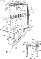
Fig. 1 is the isometrical drawing of gas turbine first order rotor blade, and it adopts the blade tip type of cooling of exemplary embodiment of the present;
The radial section figure that pass through a shown in Figure 1 blade airfoil part of Fig. 2 for roughly being got along the 2-2 line;
The vertical sectional view of passing through shown in Figure 1 aerofoil of Fig. 3 for being got along the 3-3 line;
Fig. 4 is the isometrical drawing of the amplification of the aerofoil top region shown in Fig. 1;
Fig. 5 is the top view of the amplification of the posterior marginal zone that passes through the aerofoil top shown in Fig. 1 roughly got along the 5-5 line.
Detailed Description Of The Invention
Shown in Figure 1 is exemplary gas turbine first order turbine rotor blade 10, and between on-stream period, hot combustion gas 12 is directed flowing through this blade.This blade comprises a hollow aerofoil 14, is linked to be integral body with an installation dovetail 16 that constitutes on a public foundry goods usually.This aerofoil is used for spontaneous combustion gas and obtains energy.So, this dovetail with vanes fixed on the circumference of a rotor disk (not shown) of rotating in on-stream period.
As illustrated in fig. 1 and 2, this aerofoil has a crescent shape aerodynamics blade profile, and it comprises two opposite pressure flank and negative pressure sides 18,20, and they axially or along the chord length direction extend between opposite front and rear edges 22,24.This both wings side blade tip 28 outside also longitudinally the blade root 26 of leaf exhibition direction on the integral blade seat radially extends to radially.
This mesopore aerofoil can have any common internal structure, usually comprise a plurality of internal channels 30, they have some inlets that are fit on dovetail 16, by these inlets, receive cooling air 32 from gas turbine gas compressor (not shown), cool off the freezing mixture of this blade during as running.
As shown in Figure 2,9 inner flow passages 30 that radially extend are arranged in this aerofoil, supply the usefulness of cooled blade each several part according to qualifications.Two passages in the foremost at aerofoil leading edge place provide the special use of leading edge to impact cooling.Two passages in trailing edge 24 the place aheads provide the special use cooling of the thin posterior marginal zone of aerofoil.5 center-aisles are arranged to 5 logical S shape loops, with cooling aerofoil middle part.
This aerofoil comprises the film-cooling hole 34 of several arranged radiallys, they according to the needs that effective cooling is provided pass aerofoil on the pressure side and suction side.And this aerofoil comprises row's trailing edge exhaust port 36, in order to axially to discharge cooling air from last two internal channels along trailing edge.Trailing edge exhaust port 36 in embodiment shown in Fig. 1 and 2 is the structural type of groove and ends at trailing edge itself, and these grooves only are configured on the pressure side on 18 or open a gap of aerofoil thereon.Like this, the posterior marginal zone of aerofoil can be thinner, only on the pressure side forms exhaust port 36 through it simultaneously, so that blade keeps required sufficient intensity of long lifetime.
Shown in Fig. 3 and 4, a generally flat blade tip table top 38 connects airfoil pressure side and suction side, and seals several internal channels in it.This blade tip table top comprises first and second respectively along on the pressure side prolong the blade tip hummer rib 40,42 that is bonded with the suction side extension and at aerofoil front and rear edges place.This on the pressure side with blade tip around the suction side rib 40,42, and define a uncovered blade tip plenum space betwixt.
42 1 integral body of this suction side second rib extend to the extension part of common extension of the aerofoil negative pressure sidewall of trailing edge from leading edge.This on the pressure side first rib 40 constitute the extension part of airfoil pressure side walls, and extend or flush jointly in a small amount with airfoil pressure side.
More particularly, first rib 40 shown in Fig. 4 radially inwardly or downwards is recessed into aerofoil on the pressure side from aerofoil top 28, to define one within it towards outer blade tip platform 46, becomes the typical structure form of L shaped corner.Shown in Fig. 3 and 4, first rib 40 inwardly concaves from the aerofoil top with depth D and on the pressure side inwardly concaves certainly with width W, defines the blade tip platform within it.
According to the present invention, the blade tip platform 46 shown in Fig. 4 ends at a sloping platform 48, and this sloping platform axially extends back towards trailing edge, and radially extends upward towards the aerofoil top.
Two hummer ribs 40,42 shown in Fig. 4 have the identical height that exceeds the blade tip table top, to form and the radial clearance or the air gap of stator case (not shown) basically identical on every side.Blade tip platform 46 is preferably near aerofoil leading edge 22, and preferably a little in the leading edge back, to satisfy at the needs that when combustion gas 12 flow through therebetween, strengthen the blade tip cooling between on-stream period.Blade tip platform major part is arranged essentially parallel to blade tip table top 38 with roughly constant depth D and the rib that stretches and extending on it, until the intersection of the sloping platform 48 of itself and platform.The sloping platform part depth D then of platform reduces, and sloping platform and the airfoil pressure side that links the aerofoil top at this place are radially crossed.
As shown in Figure 4, first rib 40 and airfoil pressure side 18 are extended jointly or are flushed along side direction with the junction of trailing edge 24 near leading edge 22 and at it.Sloping platform 48 is arranged on the place ahead of trailing edge 24, there because the space that the lateral thickness of aerofoil posterior marginal zone is allowed than Bao Eryou.Therefore first rib 40 between the trailing edge of the sloping platform 48 of platform with on the pressure side 18 extend along axle is common, for surface on the pressure side provides the continuity of aerodynamic.
Therefore, the sloping platform 48 of platform is by crossing in the airfoil pressure side face ends in the airfoil pressure side face with depth D and width W, and in fact disappears at the radially outermost portion of trailing edge or at the aerofoil top 28 in trailing edge the place ahead.
Fig. 5 is illustrated in the enlarged portion at the aerofoil top at trailing edge place, comprises decline and its termination sloping platform 48 of blade tip platform 46.In this exemplary embodiment, the aerofoil posterior marginal zone is done thinly as far as possible, and the wall of formation airfoil pressure side and suction side must have minimum thickness to extend the life-span.So the size of internal channel 30 has the minimum dimension that can reach according to the technical ability that adopts the conventional cast method to form these passages.
In casting technique, long ceramic finger-type thing is used to define each runner, and some finger-type thing is strengthened with the thin bar that buries within it.These bars extend to the top plenum space of aerofoil, and this plenum space is defined by the additional ceramic body with these bar supportings.
Therefore, require the platform 46 shown in Fig. 5 to stop in the place ahead of aerofoil trailing edge 24 because for make this platform and suitably the internal channel of size do not have enough spaces, and require the width of the top plenum space in posterior marginal zone do try one's best little.
Fig. 4 represents that the front end edge of blade tip platform 46 axially only with on the pressure side crosses, and to keep its constant depth D, ends at its front end up to it.Therefore, the front end at the blade tip platform forms a vertical surface.
Similar therewith, the rear end of blade tip platform 46 vertically only can with on the pressure side cross, but this can cause a similar vertical surface in the rear end of blade tip platform.In fact this vertical surface can form a L shaped corner, ends at aerofoil on the pressure side at this place's platform.This corner is undesirable for the main flow direction of combustion gas stream, expression more representational corners wherein in Fig. 4, and they are radially outward-dipping.
The tilt angle that the modern three-dimensional computations flow analysis of combustion gas stream has indicated streamline shown in Figure 4.When the rear perpendicular face by above-mentioned L shaped blade tip platform, this inclination streamline can make the local retardance of streamline, and it adheres to but the rear of blade tip platform fortunately again.Combustion gas stream blocked increased it conducts heat, and the local heating at the aerofoil top of blade tip platform rear is strengthened.
Yet according to the present invention, the blade tip platform ends at the sloping platform 48 of this inclination, to eliminate the corresponding L shaped corner at above-mentioned undesirable vertical surface of blade tip platform and airfoil pressure side intersection and blade tip platform.
For the reason of above-mentioned manufacture view, the place ahead that the sloping platform 48 of the platform shown in Fig. 4 is preferably in trailing edge 24 stops, and on the pressure side 18 extends jointly along blade tip platform and sloping platform.The sloping platform 48 of platform tilts with little acute angle A with respect to straight basically blade tip platform 48, so that mate basically with the angle orientation or the inclination of desirable design point and combustion gas stream streamline in engine running.
Therefore, the sloping platform 48 of the inclination of platform separates at the place ahead and the aerofoil trailing edge of aerofoil trailing edge, so that the smooth airfoil pressure side 18 to blade tip platform and the tight rear of sloping platform provides unbroken continuity, make combustion gas 12 along on the pressure side and along the rear part maintenance of the first blade tip rib 40 on the pressure side adhering between sloping platform and the trailing edge.The streamline of combustion-gas flow can be parallel to corresponding sloping platform sloping platform 48 usually and flow, and makes the separation of combustion gas stream minimum or be prevented from, and these combustion gas are subsequently along on the pressure side adhering to again.
When combustion gas flows through the tight rear of sloping platform of platform, can keep being attached on the pressure side, and can not be subjected to its injurious effects.
The sloping platform of platform preferably makes domatic or to tilt to aerofoil top and trailing edge radially outward with each adopted substantially horizontal of blade tip platform, top table top 38 and the first blade tip rib 40 inclination angle A into about 12 °.
As shown in Figure 3, blade tip platform 46 preferably is connected with first rib 40 with a right angle corner.In addition, row's platform exhaust port 50 inwardly passes top table top 38, is communicated with 30 one-tenth fluids of inner flow passage, so that discharge freezing mixture 32 from the there.As shown in Figure 4, this row's deck hole 50 is according to discharging need extending along the length of blade tip platform and sloping platform of freezing mixture.
Freezing mixture in blade tip platform stream provides the film cooling to hummer rib 40 on the pressure side, and a heat shield that stops the hot combustion gas heating effect is provided.The blade tip platform enjoy in above-mentioned patent disclosed original blade tip platform benefit, and enjoy other benefit owing to the rear end at platform forms the platform sloping platform 48 that tilts.
This paper illustrated be considered to the present invention preferably with exemplary embodiment in, according to the explanation of this paper, other modification of the present invention can become apparent for the Professional visitors.Therefore, need guarantee that these modification all drop in true spirit of the present invention and the scope in appended claims.
Claims (20)
1. a gas turbine blades (10) comprising:
One has along the string between the front and rear edges (22,24) and extends and along opposite on the pressure side (18) and the aerofoil (14) of suction side (20) that the leaf extension between blade root (26) and the blade tip (28) is stretched;
One connect described on the pressure side with the blade tip table top (38) of suction side, comprise first and second ribs (40,42) along its extension, define a blade tip plenum space at this both wings intercostal;
Described first rib (40) is recessed on the pressure side described, defines a blade tip platform (46) within it, and described blade tip platform ends at a sloping platform (48) in the place ahead of trailing edge (24), and this sloping platform is outward-dipping towards described aerofoil top.
2. the blade of claim 1 is characterized in that described blade tip platform starts near the described leading edge (22), and major part is arranged essentially parallel to the sloping platform (48) that described blade tip table top (38) extends to described platform, reduces the degree of depth along it then.
3. the blade of claim 2, it is characterized in that described first rib (40) extends with described airfoil pressure side (18) is common between the sloping platform (48) of described platform and described trailing edge (24), described sloping platform (48) on the pressure side crosses with described in described top (28) on aspect two of the degree of depth and width.
4. the blade of claim 3, it is characterized in that described aerofoil (14) also comprises row's trailing edge exhaust port (36), they have breach on the pressure side on (18), and end at trailing edge, the sloping platform of described platform (48) is with interval in its place ahead, and combustion gas stream is adhered to along the maintenance on the pressure side between them.
5. the blade of claim 4 is characterized in that the sloping platform (48) of described platform favours on the pressure side (18), so as basically with the streamline coupling of combustion gas stream.
6. the blade of claim 4 is characterized in that the sloping platform (48) of described platform favours about 12 ° of described blade tip platform (46).
7. the blade of claim 4 is characterized in that the sloping platform (48) of described platform is flat basically.
8. the blade of claim 4 is characterized in that described blade tip platform (46) is flat basically, and the sloping platform of described platform (48) is flat basically, adjoins with an obtuse angle and described blade tip platform.
9. the blade of claim 4 is characterized in that described blade tip platform (46) adjoins with a corner and first rib (40).
10. gas turbine blades (10) with a blade tip platform (46), this platform is along blade tip hummer rib (40) recessed on the pressure side (18), described platform ends at a sloping platform (48) that tilts in trailing edge (24) the place ahead, described sloping platform is intersected on the pressure side described.
11. the blade of claim 10, it is characterized in that also comprising some internal channels (30) in it, flow through therebetween with conduct coolant, described blade tip platform (46) comprises several rows of pore (50), become fluid to be communicated with described passage, so that discharge described freezing mixture along described platform and sloping platform.
12. the blade of claim 11, it is characterized in that also comprising one with on the pressure side (18) at interval and the suction side (20) of extension between described trailing edge (24) and opposite leading edge (22), described blade tip platform (46) starts from the pressure side going up of leading edge (22) rear, and has the constant substantially degree of depth until sloping platform (48), the described sloping platform degree of depth reduces gradually, and (18) cross with on the pressure side.
13. the blade of claim 12, also (18) cross with on the pressure side to it is characterized in that described sloping platform (48) broad ways.
14. the blade of claim 13 is characterized in that the sloping platform (48) of described platform favours on the pressure side, so as with can mate substantially along the streamline of the described combustion gas stream that on the pressure side flows.
15. the blade of claim 13 is characterized in that the sloping platform (48) of described platform favours about 12 ° of blade tip platform (46).
16. one kind comprises the gas turbine blades (10) of ending aerofoil (14) and whole dovetail, described aerofoil have blade root is arranged (26) to blade tip (28) in front and rear edges (22,24) extend between opposite on the pressure side and suction side, described blade tip comprises respectively the first and second blade tip ribs (40 that extend with suction side along on the pressure side, 42), the first blade tip rib is recessed on the pressure side (18) aspect the degree of depth and width two, define a blade tip platform (46) within it, it extends to trailing edge (24), ends at a sloping platform (48) that tilts.
17. (28) cross with airfoil pressure side at the top on the degree of depth and width both direction for the blade of claim 16, the sloping platform (48) that it is characterized in that platform.
18. the blade of claim 17 is characterized in that the sloping platform (48) of platform favours on the pressure side, so as with can cooperate substantially along the streamline of the described combustion gas stream that on the pressure side flows.
19. the blade of claim 18 is characterized in that the sloping platform (48) of described platform ends at the place ahead of trailing edge, extend jointly along described blade tip platform and sloping platform described on the pressure side (18).
20. the blade of claim 19 is characterized in that the sloping platform (48) of described platform favours about 12 ° of blade tip platform (46).
Applications Claiming Priority (2)
| Application Number | Priority Date | Filing Date | Title |
|---|---|---|---|
| US09/965,349 US6554575B2 (en) | 2001-09-27 | 2001-09-27 | Ramped tip shelf blade |
| US09/965349 | 2001-09-27 |
Publications (1)
| Publication Number | Publication Date |
|---|---|
| CN1408988A true CN1408988A (en) | 2003-04-09 |
Family
ID=25509844
Family Applications (1)
| Application Number | Title | Priority Date | Filing Date |
|---|---|---|---|
| CN02142392A Pending CN1408988A (en) | 2001-09-27 | 2002-09-27 | Blade with slope blade-tip platform |
Country Status (10)
| Country | Link |
|---|---|
| US (1) | US6554575B2 (en) |
| EP (1) | EP1298285B1 (en) |
| JP (1) | JP4108427B2 (en) |
| KR (1) | KR20030028393A (en) |
| CN (1) | CN1408988A (en) |
| AT (1) | ATE335917T1 (en) |
| DE (1) | DE60213733T2 (en) |
| ES (1) | ES2269615T3 (en) |
| RU (1) | RU2002125720A (en) |
| TW (1) | TW558591B (en) |
Cited By (9)
| Publication number | Priority date | Publication date | Assignee | Title |
|---|---|---|---|---|
| CN101191424A (en) * | 2006-11-30 | 2008-06-04 | 通用电气公司 | Turbine blade and turbine blade cooling system and methods |
| CN102168584A (en) * | 2010-02-25 | 2011-08-31 | 通用电气公司 | Turbine blade with shielded coolant supply passageway |
| CN102713160A (en) * | 2009-12-31 | 2012-10-03 | 斯奈克玛 | Inner ventilation blade |
| CN101446208B (en) * | 2007-11-26 | 2014-02-12 | 斯奈克玛 | Turbomachine vane |
| CN104033186A (en) * | 2013-03-05 | 2014-09-10 | 株式会社日立制作所 | Gas Turbine Blade |
| CN104520538A (en) * | 2012-08-09 | 2015-04-15 | 通用电气公司 | Turbine blades |
| CN103883361B (en) * | 2012-12-20 | 2016-05-04 | 中航商用航空发动机有限责任公司 | Turbo blade |
| CN105937411A (en) * | 2015-03-05 | 2016-09-14 | 通用电气公司 | Airfoil and method for managing pressure at tip of airfoil |
| CN110872952A (en) * | 2018-09-04 | 2020-03-10 | 通用电气公司 | Turbine engine component with hollow pin |
Families Citing this family (43)
| Publication number | Priority date | Publication date | Assignee | Title |
|---|---|---|---|---|
| US6790005B2 (en) * | 2002-12-30 | 2004-09-14 | General Electric Company | Compound tip notched blade |
| US7118342B2 (en) * | 2004-09-09 | 2006-10-10 | General Electric Company | Fluted tip turbine blade |
| US7270514B2 (en) * | 2004-10-21 | 2007-09-18 | General Electric Company | Turbine blade tip squealer and rebuild method |
| US7510376B2 (en) * | 2005-08-25 | 2009-03-31 | General Electric Company | Skewed tip hole turbine blade |
| EP1764477B1 (en) * | 2005-09-14 | 2008-07-02 | General Electric Company | Fluted tip turbine blade |
| US7300250B2 (en) * | 2005-09-28 | 2007-11-27 | Pratt & Whitney Canada Corp. | Cooled airfoil trailing edge tip exit |
| US7287959B2 (en) * | 2005-12-05 | 2007-10-30 | General Electric Company | Blunt tip turbine blade |
| US7686578B2 (en) * | 2006-08-21 | 2010-03-30 | General Electric Company | Conformal tip baffle airfoil |
| US8500396B2 (en) * | 2006-08-21 | 2013-08-06 | General Electric Company | Cascade tip baffle airfoil |
| US8512003B2 (en) * | 2006-08-21 | 2013-08-20 | General Electric Company | Tip ramp turbine blade |
| US7607893B2 (en) * | 2006-08-21 | 2009-10-27 | General Electric Company | Counter tip baffle airfoil |
| US8632311B2 (en) * | 2006-08-21 | 2014-01-21 | General Electric Company | Flared tip turbine blade |
| US8425183B2 (en) | 2006-11-20 | 2013-04-23 | General Electric Company | Triforial tip cavity airfoil |
| US7914257B1 (en) | 2007-01-17 | 2011-03-29 | Florida Turbine Technologies, Inc. | Turbine rotor blade with spiral and serpentine flow cooling circuit |
| US8083484B2 (en) * | 2008-12-26 | 2011-12-27 | General Electric Company | Turbine rotor blade tips that discourage cross-flow |
| US8092179B2 (en) * | 2009-03-12 | 2012-01-10 | United Technologies Corporation | Blade tip cooling groove |
| US8186965B2 (en) * | 2009-05-27 | 2012-05-29 | General Electric Company | Recovery tip turbine blade |
| US8371815B2 (en) * | 2010-03-17 | 2013-02-12 | General Electric Company | Apparatus for cooling an airfoil |
| CN102182518B (en) * | 2011-06-08 | 2013-09-04 | 河南科技大学 | Turbine cooling blade |
| CA2859993C (en) | 2011-12-29 | 2019-10-01 | Rolls-Royce North American Technologies Inc. | Gas turbine engine and turbine blade |
| US9091177B2 (en) | 2012-03-14 | 2015-07-28 | United Technologies Corporation | Shark-bite tip shelf cooling configuration |
| US9284845B2 (en) * | 2012-04-05 | 2016-03-15 | United Technologies Corporation | Turbine airfoil tip shelf and squealer pocket cooling |
| US9228442B2 (en) * | 2012-04-05 | 2016-01-05 | United Technologies Corporation | Turbine airfoil tip shelf and squealer pocket cooling |
| US9429027B2 (en) | 2012-04-05 | 2016-08-30 | United Technologies Corporation | Turbine airfoil tip shelf and squealer pocket cooling |
| US9103217B2 (en) * | 2012-10-31 | 2015-08-11 | General Electric Company | Turbine blade tip with tip shelf diffuser holes |
| US9453419B2 (en) | 2012-12-28 | 2016-09-27 | United Technologies Corporation | Gas turbine engine turbine blade tip cooling |
| US9464528B2 (en) | 2013-06-14 | 2016-10-11 | Solar Turbines Incorporated | Cooled turbine blade with double compound angled holes and slots |
| FR3024749B1 (en) * | 2014-08-05 | 2016-07-22 | Snecma | TANK TOP TANK OF A TURBOMACHINE TURBINE |
| WO2016164533A1 (en) | 2015-04-08 | 2016-10-13 | Horton, Inc. | Fan blade surface features |
| US10107108B2 (en) | 2015-04-29 | 2018-10-23 | General Electric Company | Rotor blade having a flared tip |
| EP3118413B1 (en) * | 2015-06-24 | 2019-06-26 | United Technologies Corporation | Turbine airfoil tip shelf and squealer pocket cooling |
| US9885243B2 (en) | 2015-10-27 | 2018-02-06 | General Electric Company | Turbine bucket having outlet path in shroud |
| US10156145B2 (en) * | 2015-10-27 | 2018-12-18 | General Electric Company | Turbine bucket having cooling passageway |
| US10508554B2 (en) | 2015-10-27 | 2019-12-17 | General Electric Company | Turbine bucket having outlet path in shroud |
| US10436040B2 (en) * | 2017-01-13 | 2019-10-08 | Rolls-Royce Corporation | Airfoil with dual-wall cooling for a gas turbine engine |
| US10822103B2 (en) * | 2017-02-10 | 2020-11-03 | General Electric Company | Propulsor assembly for an aircraft |
| US10533429B2 (en) * | 2017-02-27 | 2020-01-14 | Rolls-Royce Corporation | Tip structure for a turbine blade with pressure side and suction side rails |
| JP2018150828A (en) * | 2017-03-10 | 2018-09-27 | 川崎重工業株式会社 | Cooling structure for turbine blade |
| US11319819B2 (en) * | 2017-05-30 | 2022-05-03 | Siemens Energy Global GmbH & Co. KG | Turbine blade with squealer tip and densified oxide dispersion strengthened layer |
| US10822959B2 (en) * | 2017-06-15 | 2020-11-03 | Raytheon Technologies Corporation | Blade tip cooling |
| US11118462B2 (en) * | 2019-01-24 | 2021-09-14 | Pratt & Whitney Canada Corp. | Blade tip pocket rib |
| CN111022127B (en) * | 2019-11-29 | 2021-12-03 | 大连理工大学 | Turbine blade trailing edge curved exhaust split structure |
| US11371359B2 (en) | 2020-11-26 | 2022-06-28 | Pratt & Whitney Canada Corp. | Turbine blade for a gas turbine engine |
Family Cites Families (7)
| Publication number | Priority date | Publication date | Assignee | Title |
|---|---|---|---|---|
| US4497613A (en) * | 1983-01-26 | 1985-02-05 | General Electric Company | Tapered core exit for gas turbine bucket |
| US5261789A (en) | 1992-08-25 | 1993-11-16 | General Electric Company | Tip cooled blade |
| US6190129B1 (en) * | 1998-12-21 | 2001-02-20 | General Electric Company | Tapered tip-rib turbine blade |
| US6086328A (en) * | 1998-12-21 | 2000-07-11 | General Electric Company | Tapered tip turbine blade |
| US6059530A (en) * | 1998-12-21 | 2000-05-09 | General Electric Company | Twin rib turbine blade |
| US6164914A (en) * | 1999-08-23 | 2000-12-26 | General Electric Company | Cool tip blade |
| US6422821B1 (en) * | 2001-01-09 | 2002-07-23 | General Electric Company | Method and apparatus for reducing turbine blade tip temperatures |
-
2001
- 2001-09-27 US US09/965,349 patent/US6554575B2/en not_active Expired - Lifetime
-
2002
- 2002-09-12 TW TW091120876A patent/TW558591B/en not_active IP Right Cessation
- 2002-09-18 ES ES02256478T patent/ES2269615T3/en not_active Expired - Lifetime
- 2002-09-18 DE DE60213733T patent/DE60213733T2/en not_active Expired - Lifetime
- 2002-09-18 EP EP02256478A patent/EP1298285B1/en not_active Expired - Lifetime
- 2002-09-18 AT AT02256478T patent/ATE335917T1/en not_active IP Right Cessation
- 2002-09-26 RU RU2002125720/06A patent/RU2002125720A/en not_active Application Discontinuation
- 2002-09-26 KR KR1020020058296A patent/KR20030028393A/en not_active Application Discontinuation
- 2002-09-26 JP JP2002280108A patent/JP4108427B2/en not_active Expired - Fee Related
- 2002-09-27 CN CN02142392A patent/CN1408988A/en active Pending
Cited By (15)
| Publication number | Priority date | Publication date | Assignee | Title |
|---|---|---|---|---|
| CN101191424A (en) * | 2006-11-30 | 2008-06-04 | 通用电气公司 | Turbine blade and turbine blade cooling system and methods |
| CN101446208B (en) * | 2007-11-26 | 2014-02-12 | 斯奈克玛 | Turbomachine vane |
| CN102713160A (en) * | 2009-12-31 | 2012-10-03 | 斯奈克玛 | Inner ventilation blade |
| CN102168584B (en) * | 2010-02-25 | 2015-06-17 | 通用电气公司 | Turbine blade with shielded coolant supply passageway |
| CN102168584A (en) * | 2010-02-25 | 2011-08-31 | 通用电气公司 | Turbine blade with shielded coolant supply passageway |
| CN104520538A (en) * | 2012-08-09 | 2015-04-15 | 通用电气公司 | Turbine blades |
| CN104520538B (en) * | 2012-08-09 | 2016-06-01 | 通用电气公司 | Turbine blade |
| CN103883361B (en) * | 2012-12-20 | 2016-05-04 | 中航商用航空发动机有限责任公司 | Turbo blade |
| CN104033186A (en) * | 2013-03-05 | 2014-09-10 | 株式会社日立制作所 | Gas Turbine Blade |
| CN104033186B (en) * | 2013-03-05 | 2016-10-26 | 三菱日立电力系统株式会社 | Gas turbine blades |
| US9828859B2 (en) | 2013-03-05 | 2017-11-28 | Mitsubishi Hitachi Power Systems, Ltd. | Gas turbine blade with inner and outer cooling holes |
| CN105937411A (en) * | 2015-03-05 | 2016-09-14 | 通用电气公司 | Airfoil and method for managing pressure at tip of airfoil |
| CN110872952A (en) * | 2018-09-04 | 2020-03-10 | 通用电气公司 | Turbine engine component with hollow pin |
| US11377963B2 (en) | 2018-09-04 | 2022-07-05 | General Electric Company | Component for a turbine engine with a conduit |
| CN110872952B (en) * | 2018-09-04 | 2022-10-14 | 通用电气公司 | Turbine engine component with hollow pin |
Also Published As
| Publication number | Publication date |
|---|---|
| US20030059304A1 (en) | 2003-03-27 |
| RU2002125720A (en) | 2004-04-10 |
| JP2003129802A (en) | 2003-05-08 |
| EP1298285B1 (en) | 2006-08-09 |
| DE60213733D1 (en) | 2006-09-21 |
| EP1298285A3 (en) | 2004-11-24 |
| DE60213733T2 (en) | 2007-06-28 |
| KR20030028393A (en) | 2003-04-08 |
| JP4108427B2 (en) | 2008-06-25 |
| ES2269615T3 (en) | 2007-04-01 |
| EP1298285A2 (en) | 2003-04-02 |
| ATE335917T1 (en) | 2006-09-15 |
| TW558591B (en) | 2003-10-21 |
| US6554575B2 (en) | 2003-04-29 |
Similar Documents
| Publication | Publication Date | Title |
|---|---|---|
| CN1408988A (en) | Blade with slope blade-tip platform | |
| JP4801513B2 (en) | Cooling circuit for moving wing of turbomachine | |
| JP3844324B2 (en) | Squeezer for gas turbine engine turbine blade and gas turbine engine turbine blade | |
| EP0718467B1 (en) | Cooling of turbine blade tip | |
| EP0716217B1 (en) | Trailing edge ejection slots for film cooled turbine blade | |
| CN101131096B (en) | Flared tip turbine blade | |
| CN1995708B (en) | Blade with parallel serpentine cooling channels | |
| CN104594955B (en) | Tip ramp turbine blade | |
| JP4716375B2 (en) | Blunt tip turbine blade | |
| US5468125A (en) | Turbine blade with improved heat transfer surface | |
| JP4486216B2 (en) | Airfoil isolation leading edge cooling | |
| US5261789A (en) | Tip cooled blade | |
| US6790005B2 (en) | Compound tip notched blade | |
| CA2867847C (en) | Turbine airfoil trailing edge cooling slots | |
| US7322797B2 (en) | Damper cooled turbine blade | |
| CA2518979C (en) | Fluted tip turbine blade | |
| US6568909B2 (en) | Methods and apparatus for improving engine operation | |
| EP1544411A2 (en) | Turbine blade frequency tuned pin bank | |
| US6672832B2 (en) | Step-down turbine platform | |
| EP1118747A2 (en) | An aerofoil for an axial flow turbomachine | |
| CN1690365A (en) | Methods and apparatus for assembling gas turbine engine rotor assemblies | |
| CN1550650A (en) | Microcircuit cooling for a turbine blade tip | |
| EP1231359A2 (en) | Method and apparatus for reducing turbine blade tip region temperatures | |
| US20070122282A1 (en) | Central cooling circuit for a moving blade of a turbomachine | |
| EP1605137A1 (en) | Cooled rotor blade |
Legal Events
| Date | Code | Title | Description |
|---|---|---|---|
| C06 | Publication | ||
| PB01 | Publication | ||
| C02 | Deemed withdrawal of patent application after publication (patent law 2001) | ||
| WD01 | Invention patent application deemed withdrawn after publication |