CN1339331A - Device and method for treating waste gas and pulse generator used in it - Google Patents
Device and method for treating waste gas and pulse generator used in it Download PDFInfo
- Publication number
- CN1339331A CN1339331A CN01119455A CN01119455A CN1339331A CN 1339331 A CN1339331 A CN 1339331A CN 01119455 A CN01119455 A CN 01119455A CN 01119455 A CN01119455 A CN 01119455A CN 1339331 A CN1339331 A CN 1339331A
- Authority
- CN
- China
- Prior art keywords
- voltage
- low
- short
- pulse generator
- exhaust gas
- Prior art date
- Legal status (The legal status is an assumption and is not a legal conclusion. Google has not performed a legal analysis and makes no representation as to the accuracy of the status listed.)
- Granted
Links
Images


Classifications
-
- B—PERFORMING OPERATIONS; TRANSPORTING
- B01—PHYSICAL OR CHEMICAL PROCESSES OR APPARATUS IN GENERAL
- B01D—SEPARATION
- B01D53/00—Separation of gases or vapours; Recovering vapours of volatile solvents from gases; Chemical or biological purification of waste gases, e.g. engine exhaust gases, smoke, fumes, flue gases, aerosols
- B01D53/34—Chemical or biological purification of waste gases
-
- F—MECHANICAL ENGINEERING; LIGHTING; HEATING; WEAPONS; BLASTING
- F01—MACHINES OR ENGINES IN GENERAL; ENGINE PLANTS IN GENERAL; STEAM ENGINES
- F01N—GAS-FLOW SILENCERS OR EXHAUST APPARATUS FOR MACHINES OR ENGINES IN GENERAL; GAS-FLOW SILENCERS OR EXHAUST APPARATUS FOR INTERNAL COMBUSTION ENGINES
- F01N3/00—Exhaust or silencing apparatus having means for purifying, rendering innocuous, or otherwise treating exhaust
- F01N3/08—Exhaust or silencing apparatus having means for purifying, rendering innocuous, or otherwise treating exhaust for rendering innocuous
- F01N3/0892—Electric or magnetic treatment, e.g. dissociation of noxious components
-
- B—PERFORMING OPERATIONS; TRANSPORTING
- B01—PHYSICAL OR CHEMICAL PROCESSES OR APPARATUS IN GENERAL
- B01D—SEPARATION
- B01D53/00—Separation of gases or vapours; Recovering vapours of volatile solvents from gases; Chemical or biological purification of waste gases, e.g. engine exhaust gases, smoke, fumes, flue gases, aerosols
- B01D53/32—Separation of gases or vapours; Recovering vapours of volatile solvents from gases; Chemical or biological purification of waste gases, e.g. engine exhaust gases, smoke, fumes, flue gases, aerosols by electrical effects other than those provided for in group B01D61/00
-
- B—PERFORMING OPERATIONS; TRANSPORTING
- B01—PHYSICAL OR CHEMICAL PROCESSES OR APPARATUS IN GENERAL
- B01J—CHEMICAL OR PHYSICAL PROCESSES, e.g. CATALYSIS OR COLLOID CHEMISTRY; THEIR RELEVANT APPARATUS
- B01J19/00—Chemical, physical or physico-chemical processes in general; Their relevant apparatus
- B01J19/08—Processes employing the direct application of electric or wave energy, or particle radiation; Apparatus therefor
- B01J19/087—Processes employing the direct application of electric or wave energy, or particle radiation; Apparatus therefor employing electric or magnetic energy
- B01J19/088—Processes employing the direct application of electric or wave energy, or particle radiation; Apparatus therefor employing electric or magnetic energy giving rise to electric discharges
-
- B—PERFORMING OPERATIONS; TRANSPORTING
- B01—PHYSICAL OR CHEMICAL PROCESSES OR APPARATUS IN GENERAL
- B01D—SEPARATION
- B01D2259/00—Type of treatment
- B01D2259/80—Employing electric, magnetic, electromagnetic or wave energy, or particle radiation
- B01D2259/818—Employing electrical discharges or the generation of a plasma
-
- B—PERFORMING OPERATIONS; TRANSPORTING
- B01—PHYSICAL OR CHEMICAL PROCESSES OR APPARATUS IN GENERAL
- B01J—CHEMICAL OR PHYSICAL PROCESSES, e.g. CATALYSIS OR COLLOID CHEMISTRY; THEIR RELEVANT APPARATUS
- B01J2219/00—Chemical, physical or physico-chemical processes in general; Their relevant apparatus
- B01J2219/08—Processes employing the direct application of electric or wave energy, or particle radiation; Apparatus therefor
- B01J2219/0803—Processes employing the direct application of electric or wave energy, or particle radiation; Apparatus therefor employing electric or magnetic energy
- B01J2219/0805—Processes employing the direct application of electric or wave energy, or particle radiation; Apparatus therefor employing electric or magnetic energy giving rise to electric discharges
- B01J2219/0807—Processes employing the direct application of electric or wave energy, or particle radiation; Apparatus therefor employing electric or magnetic energy giving rise to electric discharges involving electrodes
-
- B—PERFORMING OPERATIONS; TRANSPORTING
- B01—PHYSICAL OR CHEMICAL PROCESSES OR APPARATUS IN GENERAL
- B01J—CHEMICAL OR PHYSICAL PROCESSES, e.g. CATALYSIS OR COLLOID CHEMISTRY; THEIR RELEVANT APPARATUS
- B01J2219/00—Chemical, physical or physico-chemical processes in general; Their relevant apparatus
- B01J2219/08—Processes employing the direct application of electric or wave energy, or particle radiation; Apparatus therefor
- B01J2219/0873—Materials to be treated
- B01J2219/0875—Gas
-
- B—PERFORMING OPERATIONS; TRANSPORTING
- B01—PHYSICAL OR CHEMICAL PROCESSES OR APPARATUS IN GENERAL
- B01J—CHEMICAL OR PHYSICAL PROCESSES, e.g. CATALYSIS OR COLLOID CHEMISTRY; THEIR RELEVANT APPARATUS
- B01J2219/00—Chemical, physical or physico-chemical processes in general; Their relevant apparatus
- B01J2219/08—Processes employing the direct application of electric or wave energy, or particle radiation; Apparatus therefor
- B01J2219/0894—Processes carried out in the presence of a plasma
Abstract
A pulse generator for treating exhaust gas. In this apparatus, a plurality of stages with same structure having distribution constant line provided on the sides of input section from high-voltage power and low-voltage power. The input section from high-voltage power and low-voltage power connect to the DC charger respectively to the high-voltage lead of high-voltage input section and the low-voltage lead of low-voltage input section as grounding lead for the low-voltage lead. A low-voltage output sections with abutting distribution constant lines corresponding to each stage are connected in series. A load is disposed between the highest and lowest stage of low-voltage output sections. A short-circuiting switch is positioned between high-voltage leads and low-voltage leads.
Description
The present invention relates generally to the treatment of toxic or hazardous substances, such as NO contained in the exhaust or flue gases of thermal (electric) power plants, refuse burning facilities (i.e., refuse incinerators), toxic substance treatment facilities, and automobiles, using streamer discharge plasma (streamer discharge plasma)xAnd SOxOr the like. More particularly, the present invention relates to an electron flow discharge plasma processing apparatus and method for processing nitrogen oxides (hereinafter, written as NO) contained in exhaust gas or flue gas of a thermal power plant or the likex) And sulfur oxide (hereinafter written as SO)x) Decomposing and detoxicating. In addition, the present invention is applied to decomposition and detoxification of VOC (i.e., volatile organic compound) gases generated in chemical plants or the like. In addition, the present invention relates to a pulse generator used in the above-described exhaust gas treatment apparatus and method, and more particularly, to a pulse generator used as a power source in the case where electrodes are placed in a gas discharged from, for example, a thermal power plant or the like, and then (electron flow discharge) plasma is generated by supplying pulse power (or energy) to the electrodes (i.e., by applying a pulse voltage to the electrodes), and toxic substances are treated by electric action.
Hitherto, for example, the so-called ammonia catalytic reduction has been used for decomposing NOx. In addition, the SO-called lime-gypsum process has been used to decompose SOx. Therefore, so-called chemical treatment or treatment methods (processes) have become the removal of NO from exhaust gases or flue gasesxAnd SOxThe main technique of (1).
Meanwhile, in recent years, a method of treating exhaust gas by electron flow discharge plasma has been applied as thisA technique is provided. In an apparatus for treating toxic substances contained in exhaust gas using electron flood discharge plasma, electron flood discharge plasma is generated in a (plasma) reaction chamber. For example, the construction of a conventional pair of cylindrical reaction chambers a and another conventional pair of flat plate-shaped reaction chambers B are shown in fig. 15 and 16, respectively. In the reaction chambers A and B, respectively, by applying (identical) high voltages V between the wire electrode 01 and the cylindrical electrode 02 of FIG. 15 and between the wire electrode 06 and the plate electrode 08 of FIG. 160An electron flow discharge plasma is generated.
Electrons generated (or obtained) from the electron flow discharge plasma are accelerated by the electric field, so thatSo that these electrons become energetic electrons. Energetic electrons contained in the streamer discharge plasma cause toxic substances such as NO to collide with the toxic substancesxAnd SOxDecomposing and detoxicating. For example, in the case of decomposition of NO, such energetic electrons are associated with NO and N2Collision, thereby causing the following reaction: then, NO is decomposed.
The concentration of radicals (radial concentration) that contribute to the decomposition of NO is determined by the energy put into or applied to the electron flow plasma. Further, the reaction rate of the reaction components in the reaction system was also determined (incidentally, when the radical concentration was determined, the NO treatment rate was naturally determined).
In conventional methods and systems, a high-capacity, high-voltage power supply and a high-capacity reaction chamber are used to generate an ebullated discharge plasma. Incidentally, in fig. 15 and 16, reference numerals 04,05,010, and 011 denote current introduction lines.
However, in the case of the reactor having one high voltage power source and one reaction chamber as shown in fig. 15 or 16, constant energy is input to the entire reaction chamber regardless of the concentration of the toxic substance. Therefore, excessive waste of energy is caused on the region where the concentration of the toxic substance is low in the outlet of the reaction chamber. As a result, the energy required for the treatment is increased. That is, when the concentration of the toxic substance is lowered to a target value in the reaction chamber, an energy value not less than a required energy value will be consumed in a region where the concentration thereof is low.
In addition, the conventional electron flow discharge plasma exhaust gas treatment method has great advantages in that the equipment thereof is inexpensive and the space required for installing the equipment is small, as compared with the conventional chemical treatment or treatment method. The traditional electron flow discharge plasma waste gas treatment method has the following big defects: the energy consumption required for generating the electron flow discharge plasma is about 10Wh/Nm3And is therefore somewhat lessthan the energy consumption required in the case of conventional chemical treatment or processing (i.e., about 6 Wh/Nm)3) Twice as much.
Meanwhile, a pulse generator for generating a high voltage pulse has been used as a power source for an apparatus for performing an electron flow discharge plasma exhaust gas treatment method.
Fig. 17 is a schematic diagram showing a structure of a conventional pulse generator of a distributed constant (or parameter) type using a coaxial cable. In the figure, reference numeral 1-1And 1-2Represents a distributed constant (or parameter) line (i.e., transmission line); 3 denotes a high-voltage side wire (or wire); 4 denotes a low-voltage side wire; v0Represents a dc charger; s1Represents a short-circuit switch; v1-1And V1-2Respectively represent and distribute constant lines 1-1And 1-2The voltage generated in the direction of the corresponding arrow; z represents a load; and VPRepresenting the voltage applied to the load Z.
Distribution constant line 1-1And 1-2Are coaxial cables having a characteristic impedance Z1aAndZ1btheir length is L. Further, each distribution constant line 1-1And 1-2The composition of (A) is as follows: core (or core) 1-1aAnd 1-2aA respective core wire of; the core wires 1 are respectively surrounded by an insulating material (not shown)-1aAnd 1-2a Outer conductor 1 of-1bAnd 1-2bA corresponding conductor (made of shielding braid or covering material or the like). Incidentally, the back-folding point, i.e., the back-folded portion, is formed only by the core wire 1 having no outer layer-1aAnd 1-2aAnd (3) forming. These core wires 1-1aAnd 1-2aAre connected inseries with each other. In addition, one end (input side) of these core wiresPart) is connected to a dc charger V via a high-voltage side wire 30. On the other hand, the outer conductor 1-1bAnd 1-2bBy short-circuiting switch S1Lateral short-circuit line 5-1Are connected to each other (i.e., on the input-side terminal or end portion) and are thereby short-circuited. Furthermore, the outer conductor 1-1bIs connected to the ground line serving as the low-voltage side wire 4. Furthermore, an outer conductor 1-2bIs connected to the input side via a short-circuit switch S1To the high-voltage side lead 3.
In this case, a dc charger V operating as a power supply0Is adapted to the impedance of the load Z, i.e. Z ═ Z1a+Z1b。
In addition, in the distribution constant line 1-1And 1-2In the case where the characteristic impedances of (1) are equal to each other, i.e., in the case where very same distribution constant line 1 is used-1And 1-2In the case of these distribution constant lines 1-1And 1-2The (voltage) propagation speeds of the voltage signals in (b) are equal to each other. In the case where the dielectric constant of the insulating material is ∈ and the magnetic permeability thereof is μ, the voltage propagation velocity V is given by the following formula (1):
in the case of such a pulse generator, the switch S is short-circuited1In the initial state is open. Then, the high-voltage side wire 3 indicated by a thick line is passed through the dc charger V0Is charged to a voltage V0. In this case, the distribution constant line 1-1Output voltage of Is a V0And distributed
 constant line 1-2Output voltage V1-2is-V0. In addition, a voltage V is applied to the load ZpIs 0. Respectively on the distribution constant line 1-1And 1-2The composite of the voltage waves propagating in the forward direction is represented by the sum of the forward wave and the backward wave shown at the time when t is 0 in fig. 18(a) and 18 (b).
That is, fig. 18(a) and 18(b) show that the short-circuiting switch S is completed after reception when time t is 01Respectively on the distributed constant line 1-1And 1-2Middle transmissionThe state of the propagating voltage wave. More precisely, these figures corresponding to the instant t ═ 0 represent the very close proximity short-circuit switch S1The state of these voltage waves before closing. At time t equal to L/2v, in distribution constant line 1-2In the short-circuit switch S1Voltage polarity inversion occurs in the short-circuit switch side portion of the side. On the contrary, in the distribution constant line 1-1Because of the short-circuit switch S1The short-circuit switch side ends on the side and load Z side and the load side ends thereof are open ends (to be precise, the two ends or ends are considered open ends because the exchange of energy actually takes place at the load and at each distribution constant line 1-1And 1-2But the exchanged energy is cancelled).
Next, at time t equal to L/v, thedistribution constant line 1 on the load Z side-2Is put into a short-circuit state so that a voltage V applied to the load ZpBecomes V0. This results in a distribution constant line 1-1A voltage change occurs. As described above, charger V0Is matched with the impedance of the load Z in the distributed constant line 1-1And 1-2Are not reflected by their end faces but start to propagate therefrom to the load Z. Subsequently, the voltage generated during the time between the times t-L/v and t-3L/v is applied to and absorbed by the load, as shown in fig. 18 (c). As a result, has a peak value (or potential) V0And a voltage having a pulse width of 2L/v is applied to the load Z as shown in fig. 18 (c).
Then, when the switch S is short-circuited1When released, i.e. disconnected, the pulse generator is put into the initial state again. The above process is repeatedThe process is repeated.
In the case where the peak voltage is raised using the device shown in fig. 17, the device constructed as shown in fig. 19 can satisfy such an object by stacking the devices in a manner independent of each other.
In FIG. 19, reference numeral V0Denotes a DC charger, S1,S2,…,SNDenotes a short-circuit switch, 1-1,1-2,2-1,2-2,…N-1,N-2A distribution constant line is represented; l represents the length of each distribution constant line; z represents a load; vp represents the output voltage applied to the load Z; 3 denotes a high-voltage side wire; 4 denotes a low-voltage side wire; 5-1,5-2,5-NIndicating a short-circuited line. Here, it should be noted that each pair of outer conductors ((1)-2b,2-1b),(2-2b,3-1b),…,((N-1)-2b,N-1b) Each pair of which is connected to each other as the upper stage and the lower stage and is on a distribution constant line 1-1,1-2,2-1,2-2,…,N-1,N-2Is connected to the output side terminal or end portion via a connecting line 9-1,9-2,…,9-(N-1)Are connected in series with each other. On the other hand, the outer conductor pair ((1)-2b,2-1b),(2-2b,3-1b),…,((N-1)-2b,N-1b) At short-circuit switch S1,S2,…,SNDistribution constant line 1 on the side-1,1-2,2-1,2-2,…,N-1,N-2Are not connected to each other. The circuit shown in fig. 20 is an equivalent circuit of the circuit shown in fig. 19. In fig. 20, like reference numerals refer to like parts of the circuit of fig. 19. And, a description of these components (redundancy) is omitted here.
Here, it is considered to use all the distribution constant lines 1 from the lowermost level (i.e., the first level) to the uppermost level (i.e., the nth level) as seen in the figure-1,1-2,2-1,2-2,…,N-1And N-2Have the same characteristic impedance and the same length. Incidentally, in this case, it is assumed that the load impedance Z matches the power supply impedance, i.e., Z ═ Z1a+Z1b+Z2a+Z2b+…+ZNa+ZNb。
In the initial state, the short-circuit switch S1,S2,…,SNIs disconnected. Further, a high-voltage side wire 3 shown by a thick line is passed through a dc charger V0Is charged to a voltage V0。
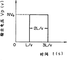
When charging is completed, the short-circuit switch S1,S2,…,SNAt time t, 0, the switch is turned on simultaneously. If short-circuit switch S1,S2,…,SNIs turned on completely simultaneously, the voltage Vp applied to the load 2 at this time has a waveform as shown in fig. 21. Therefore, let the peak voltage be NV0And a pulse having a pulse width of 2L/v is supplied to the load Z.
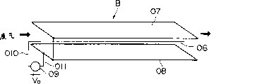
Fig. 22 is a schematic diagram showing the structure of another conventional pulse generator of the distributed constant type using parallel plates. In which like reference numerals refer to like parts in figure 6.
As shown in fig. 22, the distribution constant line 11-1And 11-2With a flat plate 11-1a、11-2aAnd 11-3Each plate has the same length L and the same width W. In addition, the flat plate 11-3Inserted in this way in the plate 11-1aAnd 11-2aI.e. the three plates are parallel to each other. At this time, the flat plate 11-2aWith connection to a dc charger V0Opposite short-circuit switch S1An input side end portion at one end portion and connected with the plate 11-1aSimilarly grounded, plate 11-1aHas an input side end connected to a low-voltage wire 4 as a ground wire. Flat plate 11-3Having an input side end connected to the high voltage side wire 3. Flat plate 11-1a,11-2aAnd 11-3Insulated by dielectric insulating material (or insulators) respectively inserted in adjacent plates (11)-1a,11-3) Between and adjacent plates (11)-3,11-2a) And has the same dielectric constant e, the same permeability mu and the same thickness D, and has a function similar to a capacitor.
Thus, the flat plate 11-1aAnd11-3Constituting a characteristic impedance of Z11aDistribution constant line of11-1And a plate 11-1bAnd 11-3Constituting a characteristic impedance of Z11bDistributed constant line 11 of-2。
In this case (these distribution constant lines 11)-1And 11-2Of) capacitance C is given by: c2 ∈ LW/D.
Therefore, the capacitance C can be increased to a large value by changing the size (i.e., length L × width W), the thickness D, or the dielectric constant ∈.
Here, it should be noted that the DC charger V0Is matched to the impedance of the load Z, i.e. Z ═ Z11a+Z11b. In addition, a distribution constant line 11-1And 11-2Have the same characteristic impedance. That is, the same distribution constant line 11 is used-1And 11-2In the case of (2), the propagation velocities v of the voltages (waves) in these distribution constant lines are equal to each other.
Even in the above-described pulse generator constituted by the parallel flat plate as such, the pulse voltage as shown in fig. 18(C) is supplied to the load Z by the action similar to that in the case of the pulse generator constituted by the coaxial cable of fig. 5.
In the case of raising the peak voltage using the circuit shown in fig. 22, the device of the structure shown in fig. 23 can be satisfied by stacking these circuits or units shown in fig. 22 in a manner independent of each other. This device corresponds to the device shown in fig. 19. Thus, in fig. 23, like reference numerals denote like parts of fig. 19. And a description of redundancy of this portion is omitted.
The pulse generator of fig. 23 can be obtained by stacking N (stages) pulse generators having the structure shown in fig. 22 and serving as constituent units. That is, the device has an N-class distribution constant line 11-1,11-2,12-1,12-2,…,NN-1,NN-2They are made of parallel flat plates. Incidentally, in each pair (or stage) of the upper and lower stages, a single flat plate serves as both the upper flat plate of the lower stage and the lower flat plate of the upper stage.
Even in the case of such a pulse generator, the short-circuit switch S is turned on by being turned on simultaneously when the predetermined preparation is completed1,S2,…,SNA pulse voltage as shown in fig. 21 is generated similarly to the case of the pulse generator in fig. 19.
However, when the pulse generator having the structure shown in fig. 19 and 23 generates a pulse, it is necessary to make the short-circuit switch S in this way1,S2,…,SNAre simultaneously turned on, but the operation of each of these switches is not performed precisely timed (i.e. fully synchronized) with those of the other switches, andthis makes it possible to see the phenomenon that the output voltage Vp drops. This is because the pulse width is in the order of nanoseconds (ns) and is therefore very short; thus, each corresponding to a short-circuit switch S1,S2,…SNThe influence of delay in application or discharge of the trigger voltage due to the difference between the wire impedances is increased, and it is difficult to synchronize the conduction operations of the short-circuiting switches (i.e., it is difficult to make N switches conduct simultaneously).
If a delay occurs in the application of the trigger voltage, the output voltages V of the three circuitspFor example, having waveforms A, B and C shown in fig. 24. Thus,the synthesized pulse (a + B + C) synthesized from these three pulses A, B and C has a waveform as shown in the figure. As a result, a pulse width of 100ns and 3V were not obtained0Ideal waveform of peak voltage.
The present invention has been made in view of the above-mentioned various problems of the conventional apparatuses and methods.
Accordingly, a first object of the present invention is to provide a multistage exhaust gas treatment device which can reduce the power consumption and size and weight of a gas treatment reactor to which power from a high voltage is supplied and which has a reaction chamber for generating an electron flow discharge plasma and decomposes toxic substances by flowing exhaust gas through the chamber.
In addition, a second object of the present invention is to provide an electron flow discharge plasma gas processing apparatus and method which saves energy by preventing the loss of electric power (or power) thereof from exceeding the energy consumption in the case of using a conventional chemical processing or treating method.
Further, a third object of the present invention is to provide a pulse generator capable of supplying outputs of a plurality of pulse generating sections connected in parallel with each other to a load and making pulses have a desired waveform.
In order to achieve the first object, according to one aspect of the present invention, there is provided an exhaust gas treatment device configured by dividing a reaction chamber into a plurality of reaction subchambers and then connecting the plurality of reaction subchambers in series into a plurality of stages. And, the device is adapted to: large amounts of energy are put into the upstream reaction subchamber and the amount of energy put into the reaction subchamber decreases progressively as the reaction subchamber to be supplied becomes closer to the most downstream reaction subchamber (less energy is supplied to each successive downstream side chamber of the plurality of chambers). Incidentally, when a plurality of reaction subchambers are connected in series, the multistage reaction subchambers may be connected in a zigzag configuration or coaxially arranged.
The energy consumption in the downstream reaction sub-chamber can be minimized by the above-described configuration of the gas treatment reactor or apparatus and method according to the invention. In addition, the efficiency of treating the poisoning material can be improved by setting the input energy according to the concentration of the poisoning material at the inlet of each reaction sub-chamber.
Further, in order to achieve the above second object of the present invention, there is provided an electron flood discharge plasma exhaust gas treatment device for detoxifying toxic components or constituents contained in exhaust gas using electron flood discharge plasma. In this device, the electron density of electrons generated in the gas decomposition unit is adjusted such that the electron density is high in a portion located forward on the upstream side (i.e., on the upstream side) of the unit exhaust gas flow, and the electron density is low in a portion located on the rear side (i.e., on the downstream side)) of the unit exhaust gas flow.
Further, the above-described electron flood discharge plasma exhaust gas treatment device is applied such that the coil density (or referred to as a wire density (i.e., the number of coils per unit length)) of the coil for generating the electron flood discharge plasma in the gas separation unit is high (or large) in the portion located on the upstream side of the unit exhaust gas flow, and the coil density is low in the portion located on the downstreamside of the unit exhaust gas flow.
In addition, in the above-described electron flow discharge plasma exhaust gas treatment device, the flow velocity of the exhaust gas in the gas decomposition unit is adjusted to a low value in a portion located on the upstream side (front side (or upstream side)) of the unit exhaust gas flow, and is adjusted to a high value in a portion located on the downstream side (rear side or (downstream side)) of the unit exhaust gas flow.
In addition to these, according to an electron flood discharge plasma exhaust gas treatment method, toxic components or constituents are detoxified by using one of the above-described electron flood discharge plasma exhaust gas treatment apparatuses.
Incidentally, the "electron flow discharge plasma" referred to herein is a discharge plasma under discharge initial conditions in which a discharge path has been formed. Thus, the "electron flow discharge plasma" is effective in treating exhaust gas.
And, in the exhaust gas, the toxic component, i.e. NOxOr SOxIs high in a portion located on the upstream side (i.e., on the inlet side) of the exhaust gas flow of the unit, while the concentration of such toxic components is low in a portion located on the downstream side (i.e., on the outlet side) of the exhaust gas flow of the unit. Furthermore, it is known that because of toxic components such as NOxOr SOxThe molecules of (2) are decomposed by energetic electrons generated by the electron flood discharge plasma, and the energetic electron generation rate in the downstream side portion of the gas decomposition unit is lower than that in the upstream side portion of the unit. Therefore, according to the technique of the present invention, the gas decomposition unit is applied such that the high-energy electron generation rate corresponds to (i.e., is proportional to) NOxOrSOxConcentration (or number of molecules). Thereby, supply of excessive energy is prevented, especially at the downstream side portion.
Indication fingerThe term "electron generation rate" as used herein is defined as the number of electrons generated per unit volume (or volume) of exhaust gas and per unit time, i.e., the electron density (/ cm) of exhaust gas3·sec)。The invention thus achieves energy savings by establishing a proportional relationship between the electron density (of the exhaust gas) and the concentration of the gas component to be decomposed. Further, in the description of the apparatus and method of the present invention, the expression "(electron density is set to) be high in the upstream side portion and low in the downstream side portion" means that the electron density is set so as to decrease in the direction from the exhaust gas upstream side to the exhaust gas downstream side thereof.
Further, to achieve the third object of the present invention, the pulse generator of the present invention employs the following configuration:
(1) the pulse generator of the present invention comprises:
a plurality of stages of the same structure each provided with a distributed constant line having a high-voltage-side input (side) end portion commonly connected to a high-voltage-side lead wire connected to a high-voltage-side end portion of the dc charger, and also having a low-voltage-side input (side) end portion commonly connected to a ground line connected to a low-voltage-side end portion of the dc charger as a low-voltage-side lead wire;
low voltage side output (side) portions of adjacent distributed constant lines each corresponding to adjacent upper and lower distributed constant lines of each stage, which are connected sequentially or in series;
aload connected between a low-voltage-side output (side) end of the uppermost distributed constant line of the uppermost stage and a low-voltage-side output (side) end of the lowermost distributed constant line of the lowermost stage; and
and a short-circuit switch connected between the high-voltage side wire and the low-voltage side wire.
(2) In the above-described structure (1), the core wire analysis four portions of the distributed constant number wire, respectively for each single-stage component unit, are connected to the high-voltage side wire. Two outer conductors, which are further surrounded by an insulating material around the remaining core portion not connected to the high-voltage side wire, are connected to the low-voltage side wire. Further, the input-side end portions of the adjacent outer conductors are short-circuited by one short-circuit line.
(3) In the above structure (1), two flat plates each having a U-shaped cross section, of the distribution constant lines each for each single-stage component unit, are connected to the low-side wire. Further, two other flat plates interposed between the two flat plates each having a U-shaped cross section through an insulating material are connected to the high-voltage side lead. In addition, the flat plate connected to the low-voltage side wire is short-circuited at its input (side) end by a short-circuit line. Further, the flat plate connected to the high-voltage side wire is short-circuited at its output (side) end by a short-circuit wire.
(4) In the above structure (1), the flat plates arranged in parallel with each other, which serve as the distributed constant lines of each single-stage component unit, respectively, are connected to the low-voltage side lead wire. Further, another plate interposed between the two parallel plates in parallel to the two parallel plates is connected to the high-voltage side wire.
Additional features, objects, and advantages of the invention will be set forth in the description which follows of a preferred embodiment with reference to the accompanying drawings in which like reference characters designate like or corresponding parts throughout the several views, and in which:
FIG. 1 is a schematic view showing the structure of a line-to-cylindrical reaction chamber of an exhaust gas treatment reactor according to a first embodiment of the present invention;
FIG. 2 is a schematic view showing the structure of a line-to-plate type reaction chamber of an exhaust gas treatment reactor according to a first embodiment of the present invention;
FIG. 3 is a graph showing a relationship between energy required to treat a poisoning substance and each amount of the poisoning substance, curves being different from each other due to their initial concentrations;
FIG. 4 is a graph showing the relationship between the energy consumption states of the multi-stage reaction chamber of the present invention and the conventional reaction chamber for comparison of the two;
FIG. 5 is a schematic view showing the structure of a zigzag-shaped multistage reaction chamber of an exhaust gas treatment reactor according to a second embodiment of the present invention;
FIG. 6 is a schematic view showing the structure of a coaxial multi-stage reaction chamber of an exhaust gas treatment reactor according to a third embodiment of the present invention;
FIG. 7 is a perspective view showing the structure of a fourth embodiment of the present invention;
FIG. 8 is a perspective view showing the structure of a fifth embodiment of the present invention;
FIG. 9 is a graph showing the relationship between the electron density and the NO decomposition rate (i.e., the decomposition rate of NO) in this embodiment of the invention;
FIG. 10 is a schematic view showing a first example of a pulse generator according to the present invention;
FIG. 11 is a circuit diagram showing an equivalent circuit of the pulse generator of FIG. 10;
FIG. 12 is a waveform diagram showing the output voltage waveform of the pulse generator of FIGS. 10 and 14;
FIG. 13(a) is a schematic view showing a component unit in a second example of the pulse generator of the present invention;
FIG. 13(b) is a block diagram showing a component structure in a second example of the pulse generator of the present invention;
FIG. 14 is a schematic view showing the overall configuration of a second example of the pulse generator of the present invention;
FIG. 15 is a schematic view showing the structure of a line-to-cylindrical reaction chamber of a conventional exhaust gas treatment reactor;
FIG. 16 is a schematic view showing the structure of a line-to-plate reaction chamber of a conventional exhaust gas treatment reactor;
fig. 17 is a schematic diagram showing a structure of a distributed constant type conventional pulse generator using a coaxial cable;
fig. 18 is a waveform diagram showing a principle of pulse generation in the pulse generator of fig. 17;
fig. 19 is a schematic view showing a structure of a pulse generator having a large capacity by stacking a plurality of stages per pulse generator shown in fig. 17;
fig.20 is a circuit diagram showing an equivalent circuit of the pulse generator of fig. 19;
FIG. 21 is a waveform diagram showing an ideal output waveform of the pulse generator of FIGS. 19 and 23;
FIG. 22 is a schematic diagram showing a configuration of a distributed constant type conventional pulse generator using parallel plates;
fig. 23 is a schematic view showing a structure of a pulse generator having a large capacity by stacking each pulse generator shown in fig. 22 in many lines; and
fig. 24 is a waveform diagram showing an actual output waveform of the pulse generator of fig. 19 and 23.
Hereinafter, preferred embodiments of the present invention, that is, an exhaust gas treatment device (or a multi-stage exhaust gas treatment reactor) embodying the present invention will be described in detail with reference to the accompanying drawings. First embodiment of an exhaust gas treatment device
First, a first example of an exhaust gas treatment device embodying the present invention will be described below. FIG. 1 shows an example in which each reaction chamber of the apparatus is formed in the shape of a pair of cylinders; FIG. 2 shows an example in which each reaction chamber of the apparatus is formed in a line-to-plate structure. The working principle of the example of the device in fig. 1 is the same as that of the example of the device in fig. 2. As shown in FIGS. 1 and 2, the n-stage reaction chamber R-1,R-2… and Rn are connected in series in the direction of exhaust gas flow. In addition, a high-voltage power supply or power supply V1,V2… and Vn are respectively connected to the reaction chamber R-1,R-2… and Rn.
The relationship between the energy required to treat the poisoning substances and the amounts of the respective poisoning substances (i.e., their elimination rates) that differ from each other due to their initial concentrations is shown in fig. 3.
As can be seen from the characteristic curve, i.e., the graph, of fig. 3, if the initial concentration of the toxic substance is high, the energy required to achieve the same rejection rate increases. Conversely, the energy consumption of the device can be reduced by inputting energy corresponding to the concentration of the toxic substance into the reaction chamber of the device.
The concentration of radicals contributing to the decomposition of the toxic substance is determined by the initial concentration of the toxic substance and the energy input or applied to the electron flood discharge plasma. In addition, the reaction rate of the reaction components of the reaction system was also determined. Therefore, the lower the initial concentration of the toxic substance, the lower the energy input and required to obtain the same rejection rate (i.e., when the initial concentration thereof is low, the number of molecules of the toxic substance to be decomposed is reduced, and as a result, the decomposition of the toxic substance can be achieved by inputting low energy to the apparatus).
As shown in FIG. 4, the reaction chamber R1Is disposed on the upstream side of the exhaust gas so that the concentration of the toxic substance in the reaction chamber is high. Then, high energy E is input thereto1So that the amount of the poisoning substance corresponding to about 50% of the initial concentration is treated or decomposed. Then less than energy E1Optimum energy E of2Is thrown into or applied to the reaction chamber R2So that the amount of the toxic substance corresponding to about 50% of the initial concentration (i.e., the reaction chamber R)175% of its original concentration) is disposed of or decomposed. Then, the process is repeated until in the reaction chamber RnUntil the toxic substances are completely decomposed. Thus, toxic substances are excluded to a certain concentration thereof (denoted as reaction chamber R) by reducing the input energy1Initial concentration of toxic substance { 1- (50/100)n) }%). Thereby significantly reducing the energy input.
The efficiency of the treatment of the toxic substance can be increased by inputting energy corresponding to the concentration of the toxic substance contained in the exhaust gas into the reaction chamber (i.e., applying (relatively) high energy to the upstream side reaction chamber where the concentration of the toxic substance contained in the exhaust gas is high, and applying (relatively) low energy to the downstream side reaction chamber where the concentration of the toxic substance contained in the exhaust gas is low). For example, in the case where the apparatus has three stages of reaction chambers, the amount of toxic substances corresponding to about 50% of its initial concentration is decomposed in the first stage (or reaction chamber). Then, another part of the toxic substances corresponding to the remaining concentration thereof of about 50% is further decomposed in the second stage. In the third stage, a further quantity of toxic substances corresponding to a residual concentration of around 50% is then decomposed. Finally, in the third stage, a decomposition corresponding to an initial concentration of 87.5% (i.e., (1-0.5)3) X 100%) of toxic substances. In this case, the required energy is reduced by about 30% compared to that required in the case of the conventional apparatus.
Thus, as a result of the use of a multistage structure, i.e. a plurality of exhaust gas treatment reaction chambers in such a method, the device is operated in an optimum state by arbitrarily selecting the energy input into each reaction chamber, as described in the following table 1. Incidentally, in this table, symbols a, b, and c represent three cases. In addition, columns (1), (2) and (3) represent the exclusion ratio.
TABLE 1
| (1) | (2) | (3) | |
| a: | 40% | 60% | 50% |
| b: | 50% | 50% | 50% |
| c: | 60% | 60% | 60% |
Further, the number of stages can be determined by setting the processing rate corresponding to each stage according to the type of the toxic substance (for example, in the case where the rejection rate corresponding to each stage is 30% and the number of stages is 5, the amount of the toxic substance corresponding to the initial concentration of 83% (because (1-0.73) × 100% ═ 83%) is excluded). Chambers of other structures besides the wire-pair cylindrical structure and the wire-pair flat plate structure may be used as the reaction chamber. The energy input to each stage can be controlled by means of a controller connecting the reaction chamber to a device (not shown) for detecting the type of toxic substance and measuring its concentration. Second embodiment of an exhaust gas treatment device
A second embodiment of an exhaust gas treatment device according to the present invention will be described with reference to fig. 5.
This exhaust gas treatment device or reactor, i.e., the second embodiment, utilizes a multistage reactor system obtained by connecting reaction chambers of several stages, each stage including an outer cylindrical electrode 15 and an inner linear electrode 16, like a zigzag pattern.
Similarly to the case in the first embodiment, when the reaction chamber to be supplied with energy becomes closer to the most downstream side reaction chamber, the energy to be thrown into one reaction chamber is reduced. In the case of the second embodiment,the size of the entire reactor system is reduced (i.e., the size of the entire reactor system can be miniaturized) by connecting the reaction chambers 17 of several stages in series in a zigzag pattern. Third embodiment of an exhaust gas treatment device
A third embodiment of the exhaust gas treatment device according to the present invention will be described with reference to fig. 6.
In the case of this exhaust gas treatment device, i.e., the third embodiment, the outer cylindrical electrodes 30 and 40 are coaxially inserted in this order into one outer cylindrical electrode 20, so that the reaction system is constituted by the coaxially arranged outer cylindrical electrodes. The linear electrodes 21, 31 and 41 correspond to the cylindrical electrodes 20, 30 and 40, respectively. In fig. 6, black arrows indicate the flow of the process gas.
The size of the third embodiment of the treatment apparatus can be miniaturized by using a structure in which the exhaust gas to be treated flows alternately back and forth in the coaxial reaction chambers from the innermost reaction chamber to the outermost reaction chamber. In this case, the treatment device may be used to cause the exhaust gas to be treated to flow alternately back and forth in the coaxial reaction chambers from the outermost reaction chamber to the innermost reaction chamber. Therefore, the entire exhaust gas treatment device can be made compact.
As described above, in the case of the exhaust gas treatment device of the present invention, energy is supplied from the high-voltage power supply. Furthermore, each reaction chamber for generating an electron flow discharge plasma in the direction of the flow of the exhaust gas is connected in series in several stages. Therefore, when the reaction chamber to be supplied with energy becomes closer to the most downstream side reaction chamber, the energy to be thrown into one reaction chamber is reduced (less energy is supplied to the more downstream side reaction chamber of the several chambers). The power consumption of the device can be reduced. Further, miniaturization of the apparatus can be achieved by connecting the reaction chambers 17 of several stages in series in a zigzag pattern or by arranging the reaction chambers of several stages coaxially. Fourth embodiment of an exhaust gas treatment device
Fig. 7 shows the structure of a gas decomposition unit which is a main part of a fourth embodiment of (electron flow discharge plasma) exhaust gas treatment device embodying the present invention. The gas decomposition unit is provided with an inner cylinder 53 around which a coil 53 is wound and an outer cylinder 52 surrounding the inner cylinder 53. Further, an annular space passage portion 54 is formed between the inner cylinder 53 and the outer cylinder 52. The outer cylinder 52 is a hollow cylinder and is made of a conductive material such as SUS. In addition, the inner cylinder 53 is also a hollow cylinder and is made of an insulating material such as Teflon (Teflon) (the "Teflon" is a trademark of polytetrafluoroethylene), glass, or ceramic. The inner cylinder 53 and the outer cylinder 52 are coaxially disposed. Further, the width of the annular cross section of the annular space channel portion 54 (Δ R ═ R-R), the outer diameter R of the inner cylinder 53, and the inner diameter R of the outer cylinder 52 are constant in the longitudinal direction of the gas decomposition unit.
The "density" of the number of turns of the coil 51 (i.e., the wire density) is set such that the wire density is high in the front side (i.e., the upstream side) of the gas decomposition unit and is low in the rear side (i.e., the downstream side) of the gas decomposition unit. The high and low values of the wire density of the coil 51 are set so that the high energy electron generation rate corresponds to NOxOr SOxIs varied in concentration (or number of molecules). Thus, the gas decomposition unit is designed such that the electron density is high in the front side (i.e., the upstream side) of the gas decomposition unit and is low in the rear side (i.e., the downstream side) of the gas decomposition unit. Here, it should be noted that: the expression "corresponding to … change" generally means, for example: the electron density varies along a curve as shown in fig. 9 (to be explained later). Typically, several tens or hundreds of individual gas decomposition units (or cylinders) are used in each plant, each of which has a diameter of several tens of centimeters (cm) and a length of five to ten meters (m). Further, the total number of turns of the coil 51 in each single gas decomposition unit is generally in the range from several tens to several hundreds.
In the case of the embodiment of the above structure, the exhaust gas containing toxic components such as NOx and SOx flows through the annular space passage portion 54 between the inner cylinder 53 and the outer cylinder 52. On the other hand, a high-voltage ultrashort pulse (for example, its pulse width is 30ns and its voltage is 29kV) is supplied from a power supply (not shown) to the coil 51. As a result, in the unit (or device)) To produce an electron flood discharge plasma. A large number of energetic electrons are thus generated. Thus, for example, NOx is decomposed into N2And O2. Further, the cell is also adapted to make the generation rate of energetic electrons vary corresponding to the concentration (number of molecules) of NOx, SOx, or the like. Thereby, excessive energy supply to the gas decomposition unit is prevented. Fifth embodiment of an exhaust gas treatment device
Fig. 8 shows the structure of a gas decomposition unit which is a main part of a fifth embodiment of an exhaust gas treatment device (streamer discharge plasma) embodying the present invention. The gas decomposition unit is provided with an inner cylinder 73 wound with a coil 71 and an outer cylinder 72. Further, an annular space (tapered) passage portion 74 is formed between the inner cylinder 73 and the outer cylinder 72. The outer cylinder 72 is a hollow cylinder and is made of a conductive material such as SUS. The inner cylinder 73 is also a hollow cylinder and is made of an insulating material, such as teflon, glass or ceramic. The inner cylinder 73 and the outer cylinder 72 are coaxially disposed. Further, the width of the annular cross section of the annular space channel portion 74 (Δ R ═ R-R) is constant in the longitudinal direction of the gas decomposition unit, while the outer diameter R of the inner cylinder 73 and the inner diameter R of the outer cylinder 72 are arranged to gradually and continuously decrease toward the most downstream end portion. Meanwhile, the "density" of the number of turns (i.e., the wire density) of the coil 71 is set constant.
Thereby, the residence (or retention) time of the off-gas in a portion on the inlet (i.e. on the front or upstream side) side of the gas decomposition unit is (relatively) long, whereas the residence (or retention) time of the off-gas in a portion on the outlet (i.e. on the rear or downstream side) side of the gas decomposition unit is (relatively) short. In other words, the flow velocity of the exhaust gas is set such that the flow velocity of the exhaust gas is low in a portion on the front, i.e., upstream side, of the gas decomposition unit, and the flow velocity of the exhaust gas is high in a portion on the rear, i.e., downstream side, of the gas decomposition unit. Typically, several tens or hundreds of individual gas decomposition units (or cylinders) are used in each plant, each of which has a diameter of several tens of centimeters (cm) and a length of five to ten meters (m). Further, the total numberof turns of the coil 71 in each single gas decomposition unit is generally in the range from several tens to several hundreds.
Therefore, this embodiment obtains advantages and effects equivalent to those obtained as a result of the electron density being high in the front side (i.e., upstream side) portion of the gas decomposition unit and the electron density being low in the rear side (i.e., downstream side) portion of the gas decomposition unit. In other words, the fifth embodiment of the exhaust gas treatment device obtains the advantages and effects equivalent to those of the first embodiment. This is because of the electron density (/ cm)3Sec) corresponds to the volume per unit of exhaust gas and the number of electrons per unit of time. Incidentally, the inner diameter R of the outer cylinder 72 and the outer diameter R of the inner cylinder 73 are set in such a manner that the above-described advantages and effects can be obtained.
In the case of the fifth embodiment of the above structure, exhaust gas containing toxic components such as NOx and SOx flows through the annular space passage portion 74 between the inner cylinder 73 and the outer cylinder 72. On the other hand, a high-voltage ultrashort pulse (for example, its pulse width is 30ns and its voltage is 29kV) is supplied from a power supply (not shown) to the coil 71. As a result, an electron flow discharge plasma is generated in the cell (or device). A large number of energetic electrons are thus generated. Thus, for example, NOx is decomposed into N2And O2. Further, the cell is adapted such that the generation rate of energetic electrons varies corresponding to the concentration (number of molecules) of NOx, SOx, or the like. Thereby, excessive energy supply to the gas decomposition unit is prevented.Comparative example and first and second working examples
The performance of each of the following comparative examples and first and second exemplary examples was tested by passing one exhaust gas containing NO, i.e., an exhaust gas stream having a concentration of 200ppm, under the condition that the flow rate of the exhaust gas on the inlet of the unit was 150 liters (l)/minute (min).
The comparative example is a conventional apparatus employed, the number of turns of the coil is constant and the residence time of the gas is constant in the longitudinal direction of the exhaust gas treatment unit.
The first exemplary embodiment corresponds to the embodiment shown in fig. 7. Further, the wire density of the coil 51 is set such that the wire density is high in the front side portion of the gas decomposition unit and low in the rear side portion of the gas decomposition unit to achieve the condition that the electron density decreases along the straight line 61 of fig. 9.
The second exemplary embodiment corresponds to the embodiment shown in fig. 8. An embodiment of the device is provided in which the width of the annular cross-section of the annular space channel portion 74 (ar-R) is constant in the longitudinal direction of the gas decomposition unit, while the outer diameter R of the inner cylinder 73 and the inner diameter R of the outer cylinder 72 gradually and continuously decrease in the direction towards the downstream end. Thus, embodiments of the apparatus are configured such that the electron density decreases along line 61 of FIG. 9, in contrast to the first exemplary embodiment
The situation is similar in the examples.
Incidentally, as is apparent from fig. 9, the decomposition rate ζNTypically close to 70% at a location located about (1/5) the length of the gas decomposition unit. Furthermore, it can be found that the decomposition rate gradually changes.
In the following table 2, the ratio of the power loss of the first and second exemplary embodiments to the power loss of the comparative embodiment (i.e., the conventional apparatus or method) is described with respect to the respective values of the NO decomposition rate. A high voltage (i.e., 20kV) consisting of ultra-short voltage pulses (pulse width is 30ns) is provided on each of the coils 51 and 71. In the case of the first and second working examples of the present invention, the power loss is not larger than that in the case of the comparative example. Thus, it is believed that working embodiments of the present invention have significant power savings advantages over conventional devices or methods.
Incidentally, in the case of the first and second working examples of the present invention, the test was conducted using a small single unit, i.e., a cylinder having a diameter of 96mm and a length of 3.5 mm. The total number of turns of the coil is 350.
TABLE 2
| Conventional methods | According to the invention First working example | According to the invention Second working example | ||
| 80% of NO is decomposed | 1.00 | 0.49 | 0.50 | |
| 90% of NO is decomposed | 1.00 | 0.43 | 0.42 | |
| 95% of NO is decomposed | 1.00 | 0.38 | 0.39 |
As is apparent from the foregoing description, according to the present invention, the generation rate of high-energy electrons in the gas decomposition unit is varied in such a manner as to correspond to the concentrations (i.e., the number of molecules) of the poisoning substances NOx and SOx (i.e., in proportion to the concentrations). Therefore, the power loss is significantly reduced in the rear or downstream side portion of the gas decomposition unit. Further, the electron density in the front side, i.e., the upstream side portion of the gas decomposition unit is sufficient to achieve decomposition of the toxic substance. So that the gas decomposition characteristics are not deteriorated. Thereby, the energy loss of the entire apparatus can be significantly reduced. First embodiment of the pulse Generator
Fig. 10 is a schematic diagram showing a first embodiment of the pulse generator of the present invention. Fig. 11 is a circuit diagram showing an equivalent circuit of the pulse generator in fig. 10. This embodiment is obtained by modifying the pulse generator of fig. 19. Accordingly, like reference numerals refer to like parts in fig. 19. A description of these parts is omitted here.
As shown in fig. 10, in a dc charger V0And a first order distributed constant line 1-2 Outer conductor 1 of-2bIs provided with only one short-circuit switch S between the input ends1. Outer conductor (1) of each stage-2b、2-2a)、(2-2b、…、N-2a) By means of a ground line 6-1、6-2、…、6-(N-1)Are connected with each other. Thus the outer conductor 1-1b、1-2b、2-1b、2-2b、…、N-1b、N-2bIs at ground potential.
It should be noted here that: all stages from the bottom, first stage, to the top, nth stage, use the distribution constant line 1-1、1-2、2-1、2-2、…、N-1、N-2Each of the distributed constant lines has the same characteristic impedance and the same length. Furthermore, the impedance of one load Z is matched to the impedance of the power source or supply.
In such a pulse generator, a short-circuit switch S1In the initial state. Furthermore, a high-voltage side conductor 3 indicated by a thick line is passed through a DC charger V0Is charged to a voltage V0. Until the charging is completed, if the switch S is short-circuited1Is turned on at the time when t is 0, then constant lines (1) are distributed in each pair-1、1-2)、(2-1、2-2)、…、(N-1、N-2) In which a pulse width of (2L/V) and a peak voltage of V are generated0The pulse voltage of (2). As a result of the superposition of these voltage pulses, a factor N times the voltage VpIs supplied to the load Z as shown in fig. 12. Thus, one peak voltage is NV0And a pulse having a pulse width of (2L/v) is supplied to the load Z. After that, when the switch S is short-circuited1When turned off, the device is again in the initial state. The above-described process is then repeatedly performed. Second embodiment of the pulse generator
Fig. 13(a), 13(b) and 14 are schematic views showing a second embodiment of the pulse generator of the present invention. This embodiment is obtained by modifying the pulse generator of fig. 12. Therefore, the same reference numerals denote the same parts as in fig. 12. A description of these parts is omitted here.
Fig. 13(a) is a schematic diagram showing one pulse generating unit used as the first stage of the second embodiment. As shown in the figure, this pulse generating unit has a distributed constant line 21-1And 21-2. These distribution constant lines 21-1And 21-2Having a flat plate 21-1bAnd 21-2bAnd a plate 21-1aAnd 21-2aWherein the flat plate 21-1bAnd 21-2bIs folded back in the shape of a letter "U", and the plate 21-1aAnd 21-2aAre respectively inserted into the flat plates 21 folded into a letter "U" shape-1bAnd 21-2bIn (1). Further, dielectric insulating materials having the same dielectric constant ε, the same permeability μ, and the same thickness D are provided on the flat plate 21-1aAnd a plate 21-1bAnd 21-2bAnd 21-2aIn the meantime.
The pulse generator of this embodiment is constructed by superposing partial cells each including a distribution constant line 21 as a plurality of stages-1And 21-2. Therefore, this embodiment is represented by one block, as shown in fig. 13 (b). In the following description, it is assumed that the distribution constant lines I, II, …, N are represented by this box.
Further, symbols "I", "II", and "N" represent a first-stage distribution constant line, a second-stage distribution constant line, and an nth-stage distribution constant line, respectively. Terminals a, b, c, d and s in fig. 13(b) correspond to terminals a, b, c, d and s in fig. 13(a), respectively. Therefore, in the case of the distributed constant line of the first stage, the terminal s is connected to the high-voltage side wire 3. Similarly, the terminal b is connected to the low-voltage side wire 4. Further, the terminals c and d are connected to each other. And the terminal S is switched by short-circuiting the switch S1Connected to the high-voltage side lead 3.
In addition, at this time, the terminal a and the flat plate 21-2aThe input (side) ends are connected. Terminal b and plate 21-1bThe input (side) ends are connected. In addition, the terminal c and the flat plate 21-2bThe output (side) end is connected. Terminal d and plate 21-1bThe output (side) end is connected. The terminal s is connected to the short-circuit switch 8. Therefore, in shortCircuit switch S1In an off state of charge, the plate 21-1aAnd 21-2aIs at a high potential, and the plate 21-1bAnd 21-2bIs at ground potential.
Fig. 14 is a pulse generator showing the embodiment, which is constructed by superposing part of the units shown in fig. 13(b), and in fig. 14, the same reference numerals denote the same parts as in fig. 10. A description of these parts is omitted here.
As shown in fig. 14, distributed constant lines "I", "II", and "N" terminals a are connected to the high-voltage side wire 3. Further, distributed constant lines "I", "II", and "N" terminals b are connected to each other by a low-voltage side wire 4. In addition, a single short-circuit switch S1Is connected between the high-voltage side wire 3 and the low-voltage side wire 4.
The terminal c of the lower one of the two stages of each adjacent pair is connected to the other terminal via a connecting wire 9-1、9-2、…、9-(N-1)Is sequentially connected with the terminal d of the higher one of the two stages. Further, the load Z is connected between the terminal c of the top stage, i.e., the terminal c of the distributed constant line N, and the terminal d of the bottom stage, i.e., the terminal d of the distributed constant line I. And the terminal s is released or disconnected. It should be noted here that: from the bottom, i.e. first stage, to the top, i.e. Nth stageThe stepped distribution constant lines I to N have the same characteristic impedance and the same length. In addition, the impedance of the load Z matches the impedance of a dc charger as a power source.
Insuch a pulse generator, a short-circuit switch S1Is released in the initial state. Further, the high pressure side flat plate 21-1aAnd 21-2aBy means of a DC charger V0Is charged to a voltage V0. Until the charging is completed, if the switch S is short-circuited1And is turned on at a time when t is 0, the pulse voltages generated in the respective profile constant lines I to N are superimposed. As a result of the superposition of these voltage pulses, the voltage V supplied to the load ZpAs shown in fig. 12. Thus, one peak voltage is NV0And a pulse having a pulse width of 2L/v is supplied to the load Z, similarly to the case of the above-described embodiment. After that, when the switch S is short-circuited1When turned off, the device is again in the initial state. The above-described process is then repeatedly performed.
By enlarging the high-pressure side plate 21-1aAnd 21-2aAnd a low-pressure side plate 21-1bAnd 21-2bAnd increasing the capacitance of each partial cell by narrowing the gap between the plates or by using a dielectric substance having a high dielectric constant as an insulating material interposed between the plates. As a result, the capacitance of the entire pulse generator can be increased.
Further, in the case of the above-described embodiment, each partial unit of the distribution constant lines I to N is formed by the distribution constant line 21-1And 21-2And (3) forming. However, each partial unit is not limited to the distribution constant line 21-1And 21-2. For example, if each partial cell is represented by the distribution constant line 11 of FIG. 22-1And 11-2Constituted so that the same advantages and effects can be obtained. At this time, the terminal a and the flat plate 11 in fig. 13(a) and 13(b)-3And (4) connecting. Further, assume that terminal b is located similarly to flat plate 11 from then on-1aDC charger V0The ends on the sides are connected. Furthermore, the terminal c is located on the flat plate 11-1aDC charger V0The opposite side ends on the side opposite sides are connected. In addition, terminal c is located on plate 11-1bDC charger V0The opposite side ends on the side opposite sides are connected.
As in the case of the apparatus or method of the invention, the examples or embodiments of the invention described above, as a DC charger V0Is passed through a single short-circuit switch S1While being supplied to the distributed constant line 1 connected in parallel-1、1-2、2-1、2-2、…、N-1And N-2. The circuit utilizes a distributed constant line 1-1、1-2、2-1、2-2、…、N-1And N-2The difference in propagation (delay) time between them. Due to the distribution of the constant line 1-1、1-2、2-1、2-2、…、N-1And N-2Switch side S of1 Outer conductor 1 of-1b、1-2b、2-1b、2-2b、…、N-1bAnd N-2bAs a result of the grounding, these outer conductors can be represented by the thick lines of the high-side line 3 and the single short-circuit switch S1While short-circuiting.
With this structure, the single short-circuit switch S1Is sufficient. This eliminates the possibility of the occurrence of the problem of shorting the switch S1The conducting operation is performed with an inaccurate timing (i.e., not completely synchronized with the timing of the other switches), similar to the case in the conventionaldevice. Thus, a decrease in the output voltage can be prevented. Thus, the pulse generator of the present invention can be operated with one single short-circuit switch. Thus, the present invention eliminates the problems of the conventional apparatus in which the conduction operations of a plurality of short-circuiting switches are not accurately performed in synchronization with another switch and the output voltage drops. Thus, a desired or ideal large voltage pulse can be obtained according to the present invention.
Although the preferred embodiments of the present invention have been described above. However, it is to be understood that the present invention is not limited to these embodiments, and other modifications will be apparent to those skilled in the art without departing from the spirit of the present invention.
The scope of the invention is therefore intended to be determined entirely by the following claims.
Claims (4)
1. A pulse generator, comprising:
a plurality of stages of the same configuration each provided with a distributed constant line having a high-voltage-side input end portion commonly connected to a high-voltage-side lead wire connected to a high-voltage-side end portion of the dc charger and a low-voltage-side input end portion commonly connected to a ground wire as a low-voltage-side lead wire connected to a low-voltage-side end portion of the dc charger;
low voltage side output end portions of adjacently distributed constant lines each corresponding to adjacent upper and lower stages of the plurality of stages, which are connected in series;
a load connected between the low-voltage-side output end of the uppermost distributed constant line of the uppermost stage and the low-voltage-side output end of the lowermost distributed constant line of the lowermost stage; and
a short-circuit switch connected between the high-voltage side wire and the low-voltage side wire.
2. The pulse generator of claim 1, wherein: core wire folded back portions of the distributed constant wires for each single-stage component unit are connected to the high-voltage side wires, respectively; two outer conductors surrounding the remaining core wire portions not connected to the high-voltage side conductor through an insulating material are connected to the low-voltage side conductor; the input ends of adjacent outer conductors are short-circuited by a short-circuit line.
3. The pulse generator of claim 1, wherein: a first pair of flat plates each having a U-shaped cross section, which are used for distributed constant lines of each single-stage partial unit, respectively, are connected to the low-voltage side conductor, a second pair of flat plates, which are inserted between the first pair of flat plates each having a U-shaped cross section through an insulating material, are connected to the high-voltage side conductor, the first pair of flat plates connected to the low-voltage side conductor are short-circuited at input ends thereof by a short-circuit line, and the second pair of flat plates connected to the high-voltage side conductor are short-circuited at output ends thereof by a short-circuit line.
4. The pulse generator of claim 1, wherein: first and second flat plates arranged in parallel with each other, which serve as distributed constant lines of each single-stage component unit, respectively, are connected to the low-voltage side conductor, and a third flat plate interposed between the first and second parallel plates in parallelwith the first and second parallel flat plates is connected to the high-voltage side conductor.
Applications Claiming Priority (6)
| Application Number | Priority Date | Filing Date | Title |
|---|---|---|---|
| JP08082284A JP3085904B2 (en) | 1996-04-04 | 1996-04-04 | Pulse generator |
| JP082284/1996 | 1996-04-04 | ||
| JP196311/1996 | 1996-07-25 | ||
| JP08196311A JP3089213B2 (en) | 1996-07-25 | 1996-07-25 | Multistage exhaust gas treatment reactor |
| JP298326/1996 | 1996-11-11 | ||
| JP29832696A JP3349369B2 (en) | 1996-11-11 | 1996-11-11 | Streamer discharge exhaust gas treatment apparatus and method |
Related Parent Applications (1)
| Application Number | Title | Priority Date | Filing Date |
|---|---|---|---|
| CN97111642A Division CN1101716C (en) | 1996-04-04 | 1997-04-03 | Apparatus and method for treating exhaust gas and pulse generator used therefor |
Publications (2)
| Publication Number | Publication Date |
|---|---|
| CN1339331A true CN1339331A (en) | 2002-03-13 |
| CN1214848C CN1214848C (en) | 2005-08-17 |
Family
ID=27303873
Family Applications (3)
| Application Number | Title | Priority Date | Filing Date |
|---|---|---|---|
| CN97111642A Expired - Fee Related CN1101716C (en) | 1996-04-04 | 1997-04-03 | Apparatus and method for treating exhaust gas and pulse generator used therefor |
| CNB011194545A Expired - Fee Related CN1159085C (en) | 1996-04-04 | 1997-04-03 | Device and method for treating waste gas and pulse generator used in it |
| CNB011194553A Expired - Fee Related CN1214848C (en) | 1996-04-04 | 2001-05-31 | Device and method for treating waste gas and pulse generator used in it |
Family Applications Before (2)
| Application Number | Title | Priority Date | Filing Date |
|---|---|---|---|
| CN97111642A Expired - Fee Related CN1101716C (en) | 1996-04-04 | 1997-04-03 | Apparatus and method for treating exhaust gas and pulse generator used therefor |
| CNB011194545A Expired - Fee Related CN1159085C (en) | 1996-04-04 | 1997-04-03 | Device and method for treating waste gas and pulse generator used in it |
Country Status (4)
| Country | Link |
|---|---|
| US (3) | US6007681A (en) |
| KR (1) | KR100230169B1 (en) |
| CN (3) | CN1101716C (en) |
| AU (1) | AU729396B2 (en) |
Families Citing this family (43)
| Publication number | Priority date | Publication date | Assignee | Title |
|---|---|---|---|---|
| KR100223884B1 (en) * | 1997-07-10 | 1999-10-15 | 이종수 | Plasma reactor and method for treating water using the same |
| US6423190B2 (en) * | 2000-01-07 | 2002-07-23 | Delphi Technologies, Inc. | Pulse density modulation for uniform barrier discharge in a nonthermal plasma reactor |
| US6576202B1 (en) * | 2000-04-21 | 2003-06-10 | Kin-Chung Ray Chiu | Highly efficient compact capacitance coupled plasma reactor/generator and method |
| US6482368B2 (en) * | 2000-12-19 | 2002-11-19 | Delphi Technologies, Inc. | Non-thermal plasma reactor for lower power consumption |
| US8764978B2 (en) | 2001-07-16 | 2014-07-01 | Foret Plasma Labs, Llc | System for treating a substance with wave energy from an electrical arc and a second source |
| US7622693B2 (en) | 2001-07-16 | 2009-11-24 | Foret Plasma Labs, Llc | Plasma whirl reactor apparatus and methods of use |
| CN100505975C (en) * | 2002-05-08 | 2009-06-24 | Btu国际公司 | Plasma-assisted coating |
| FR2844000B1 (en) * | 2002-08-30 | 2006-03-24 | Renault Sa | EXHAUST GAS TREATMENT SYSTEM COMPRISING A GAS IONIZATION SYSTEM WITH IONIZED AIR INJECTION |
| CN1266988C (en) * | 2002-11-26 | 2006-07-26 | 广东杰特科技发展有限公司 | Industrial apparatus for plasma capable of generating random streamer discharge and application thereof |
| JP2005240738A (en) * | 2004-02-27 | 2005-09-08 | Toyota Motor Corp | Power source for plasma reactor, plasma reactor, exhaust emission control device and exhaust emission control method |
| EP1600202A1 (en) * | 2004-05-24 | 2005-11-30 | Nederlandse Organisatie voor toegepast-natuurwetenschappelijk Onderzoek TNO | Method and means for chemically modifying gases of fumes |
| JP2006261040A (en) * | 2005-03-18 | 2006-09-28 | Ngk Insulators Ltd | Plasma reactor |
| EP2012904A2 (en) * | 2006-02-17 | 2009-01-14 | Plasma Clean Limited | Gas treatment using a plurality of plasma generating reactor units |
| KR100675752B1 (en) * | 2006-09-14 | 2007-01-30 | (주) 씨엠테크 | Plasma reactor |
| FR2907306B1 (en) * | 2006-10-16 | 2009-01-16 | Gen Electric | X-RAY APPARATUS |
| KR100727861B1 (en) * | 2007-01-26 | 2007-06-14 | 한국기계연구원 | Plasma chemical reactor for pfc and other hazardous gases |
| US11806686B2 (en) | 2007-10-16 | 2023-11-07 | Foret Plasma Labs, Llc | System, method and apparatus for creating an electrical glow discharge |
| US9185787B2 (en) | 2007-10-16 | 2015-11-10 | Foret Plasma Labs, Llc | High temperature electrolysis glow discharge device |
| US8810122B2 (en) | 2007-10-16 | 2014-08-19 | Foret Plasma Labs, Llc | Plasma arc torch having multiple operating modes |
| US9516736B2 (en) | 2007-10-16 | 2016-12-06 | Foret Plasma Labs, Llc | System, method and apparatus for recovering mining fluids from mining byproducts |
| US9445488B2 (en) | 2007-10-16 | 2016-09-13 | Foret Plasma Labs, Llc | Plasma whirl reactor apparatus and methods of use |
| US9560731B2 (en) | 2007-10-16 | 2017-01-31 | Foret Plasma Labs, Llc | System, method and apparatus for an inductively coupled plasma Arc Whirl filter press |
| US8278810B2 (en) | 2007-10-16 | 2012-10-02 | Foret Plasma Labs, Llc | Solid oxide high temperature electrolysis glow discharge cell |
| US9761413B2 (en) | 2007-10-16 | 2017-09-12 | Foret Plasma Labs, Llc | High temperature electrolysis glow discharge device |
| US9051820B2 (en) | 2007-10-16 | 2015-06-09 | Foret Plasma Labs, Llc | System, method and apparatus for creating an electrical glow discharge |
| US10267106B2 (en) | 2007-10-16 | 2019-04-23 | Foret Plasma Labs, Llc | System, method and apparatus for treating mining byproducts |
| US9230777B2 (en) | 2007-10-16 | 2016-01-05 | Foret Plasma Labs, Llc | Water/wastewater recycle and reuse with plasma, activated carbon and energy system |
| CA2715973C (en) | 2008-02-12 | 2014-02-11 | Foret Plasma Labs, Llc | System, method and apparatus for lean combustion with plasma from an electrical arc |
| US10244614B2 (en) | 2008-02-12 | 2019-03-26 | Foret Plasma Labs, Llc | System, method and apparatus for plasma arc welding ceramics and sapphire |
| US8904749B2 (en) | 2008-02-12 | 2014-12-09 | Foret Plasma Labs, Llc | Inductively coupled plasma arc device |
| TWI337517B (en) * | 2008-03-04 | 2011-02-11 | Inventec Corp | Trace carrier |
| US7986196B2 (en) * | 2008-07-07 | 2011-07-26 | Bae Systems Information And Electronic Systems Integration Inc. | Method and apparatus for digital synthesis of long multi-cycle microwave pulses |
| DE102011078942A1 (en) * | 2011-07-11 | 2013-01-17 | Evonik Degussa Gmbh | Process for the preparation of higher silanes with improved yield |
| CN105143413B (en) | 2012-12-11 | 2017-07-04 | 弗雷特等离子实验室公司 | High-temperature reflux vortex reactor system, method and apparatus |
| US9699879B2 (en) | 2013-03-12 | 2017-07-04 | Foret Plasma Labs, Llc | Apparatus and method for sintering proppants |
| CN104069721B (en) * | 2014-06-10 | 2016-06-01 | 上海交通大学 | The variable diameter dielectric impedance reactor of process volatile organic contaminant |
| DE102014016380A1 (en) * | 2014-11-06 | 2016-05-12 | Brückner Maschinenbau GmbH & Co. KG | Plasma exhaust gas purification |
| WO2017150414A1 (en) | 2016-03-01 | 2017-09-08 | 日本特殊陶業株式会社 | Plasma reactor |
| CN106268225A (en) * | 2016-08-04 | 2017-01-04 | 李祖良 | A kind of microwave purifying device |
| CN106621745A (en) * | 2016-12-26 | 2017-05-10 | 江南大学 | Bamboo joint series-combined vacuum-pumping exhaust gas purification pipe |
| RU2689020C1 (en) * | 2018-10-30 | 2019-05-23 | Радченко Виталий Анатольевич | Device for the internal combustion engines emissions cleaning of the nitrogen oxides using the non-equilibrium low-temperature plasma and the absorber |
| JP7099331B2 (en) * | 2019-01-08 | 2022-07-12 | トヨタ自動車株式会社 | Exhaust purification device for internal combustion engine |
| CN113785119B (en) * | 2019-03-11 | 2023-08-15 | 南加利福尼亚大学 | System and method for plasma-based abatement |
Family Cites Families (12)
| Publication number | Priority date | Publication date | Assignee | Title |
|---|---|---|---|---|
| US3555301A (en) * | 1967-11-09 | 1971-01-12 | Us Navy | Apparatus and techniques for generating variable delay pulses from paralleled avalanche transistors |
| JPS57193118A (en) * | 1981-05-25 | 1982-11-27 | Nec Corp | Pulse generating circuit using josephson effect |
| US4695358A (en) * | 1985-11-08 | 1987-09-22 | Florida State University | Method of removing SO2, NOX and particles from gas mixtures using streamer corona |
| JP2649340B2 (en) | 1986-06-10 | 1997-09-03 | 増田 佳子 | Ultra-short pulse high-voltage charged gas purifier |
| JP2523852B2 (en) | 1989-02-13 | 1996-08-14 | 三菱電機株式会社 | High voltage pulse generator |
| JPH04285874A (en) * | 1991-03-13 | 1992-10-09 | Chubu Electric Power Co Inc | Method for locating trouble point of cable |
| JPH0680403A (en) * | 1991-07-03 | 1994-03-22 | I T M Kk | High-capacity and high-performance ozonizer |
| CN1080563A (en) * | 1992-06-20 | 1994-01-12 | 鞍山静电技术研究设计院 | The method and apparatus of low temperature normal atmosphere plasma resolving harmful gas |
| JPH06106025A (en) * | 1992-09-29 | 1994-04-19 | Mitsui Eng & Shipbuild Co Ltd | Plasma reaction vessel in nitrogen oxide decomposition device |
| US5434456A (en) * | 1993-02-09 | 1995-07-18 | The Regents Of The University Of California | Lumped transmission line avalanche pulser |
| DE4416676C2 (en) * | 1994-05-11 | 2002-11-07 | Siemens Ag | Device for the detoxification of exhaust gases from mobile systems |
| US5490973A (en) * | 1994-05-23 | 1996-02-13 | The United States Of America As Represented By The Secretary Of The Navy | Pulsed corona reactor system for abatement of pollution by hazardous agents |
-
1997
- 1997-03-27 AU AU16571/97A patent/AU729396B2/en not_active Ceased
- 1997-04-02 US US08/825,913 patent/US6007681A/en not_active Expired - Fee Related
- 1997-04-03 CN CN97111642A patent/CN1101716C/en not_active Expired - Fee Related
- 1997-04-03 CN CNB011194545A patent/CN1159085C/en not_active Expired - Fee Related
- 1997-04-04 KR KR1019970012455A patent/KR100230169B1/en not_active IP Right Cessation
-
1999
- 1999-08-09 US US09/369,843 patent/US6274006B1/en not_active Expired - Fee Related
- 1999-08-09 US US09/369,842 patent/US6344701B1/en not_active Expired - Fee Related
-
2001
- 2001-05-31 CN CNB011194553A patent/CN1214848C/en not_active Expired - Fee Related
Also Published As
| Publication number | Publication date |
|---|---|
| CN1159085C (en) | 2004-07-28 |
| US6344701B1 (en) | 2002-02-05 |
| CN1214848C (en) | 2005-08-17 |
| KR19980041701A (en) | 1998-08-17 |
| US6007681A (en) | 1999-12-28 |
| AU729396B2 (en) | 2001-02-01 |
| CN1339330A (en) | 2002-03-13 |
| CN1175475A (en) | 1998-03-11 |
| AU1657197A (en) | 1998-10-01 |
| US6274006B1 (en) | 2001-08-14 |
| KR100230169B1 (en) | 1999-11-15 |
| CN1101716C (en) | 2003-02-19 |
Similar Documents
| Publication | Publication Date | Title |
|---|---|---|
| CN1339331A (en) | Device and method for treating waste gas and pulse generator used in it | |
| DE60124661T2 (en) | Non-thermal plasma reactor with reduced power consumption | |
| US6767434B1 (en) | Method of treating substance and apparatus for carrying out the same | |
| CN101534869A (en) | Diffusive plasma treatment and material procession | |
| KR100239598B1 (en) | Multi-stage gaseous pollutant destruction apparatus and method | |
| US20130284588A1 (en) | Method for scaling plasma reactors for gas treatment and devices therefrom | |
| EP1758670B1 (en) | Method and means for chemically modifying gases or fumes | |
| CN108970348B (en) | Low-temperature plasma generator, method for treating pollutants by using low-temperature plasma and application of low-temperature plasma | |
| DE19534950C2 (en) | Device for the plasma chemical decomposition and / or destruction of pollutants | |
| US7298092B2 (en) | Device and method for gas treatment using pulsed corona discharges | |
| CN203108411U (en) | Big air volume low concentration plasma exhaust gas treatment device | |
| Jani et al. | Low-voltage operation of a plasma reactor for exhaust gas treatment by dielectric barrier discharge | |
| CN112771266A (en) | Intake plasma generator system and method | |
| JP3089213B2 (en) | Multistage exhaust gas treatment reactor | |
| JP5242425B2 (en) | Gas processing equipment | |
| JP2001038138A (en) | Method and device for treating material | |
| US20080023317A1 (en) | Device and method for gas treatment using pulsed corona discharges | |
| KR101042602B1 (en) | Plasma reactor for disposing harmful gas | |
| KR20000047389A (en) | Apparatus and method for simutaneous removal of air pollutants using non-thermal plasma technology | |
| AU729503B2 (en) | Apparatus and method for treating exhaust gas | |
| AU744677B2 (en) | Pulse generator | |
| CN108970363A (en) | A kind of compartment low-temperature plasma generator for filling ozone-decomposing agent | |
| DE102016223583B3 (en) | Method and apparatus for removing soot from gas | |
| Kogelschatz et al. | High pressure plasmas: Dielectric barrier and corona discharges | |
| DE19633368A1 (en) | Producing stable corona discharge for production of ozone from air, sulphur di:oxide oxidation, dust removal from air, nitride and sputtering processes |
Legal Events
| Date | Code | Title | Description |
|---|---|---|---|
| C10 | Entry into substantive examination | ||
| SE01 | Entry into force of request for substantive examination | ||
| C06 | Publication | ||
| PB01 | Publication | ||
| C14 | Grant of patent or utility model | ||
| GR01 | Patent grant | ||
| C19 | Lapse of patent right due to non-payment of the annual fee | ||
| CF01 | Termination of patent right due to non-payment of annual fee |