CN1328091C - Gas generator - Google Patents
Gas generator Download PDFInfo
- Publication number
- CN1328091C CN1328091C CNB038043602A CN03804360A CN1328091C CN 1328091 C CN1328091 C CN 1328091C CN B038043602 A CNB038043602 A CN B038043602A CN 03804360 A CN03804360 A CN 03804360A CN 1328091 C CN1328091 C CN 1328091C
- Authority
- CN
- China
- Prior art keywords
- combustion chamber
- gas generator
- gas
- mentioned
- cylinder element
- Prior art date
- Legal status (The legal status is an assumption and is not a legal conclusion. Google has not performed a legal analysis and makes no representation as to the accuracy of the status listed.)
- Expired - Fee Related
Links
Images

Classifications
-
- B—PERFORMING OPERATIONS; TRANSPORTING
- B60—VEHICLES IN GENERAL
- B60R—VEHICLES, VEHICLE FITTINGS, OR VEHICLE PARTS, NOT OTHERWISE PROVIDED FOR
- B60R21/00—Arrangements or fittings on vehicles for protecting or preventing injuries to occupants or pedestrians in case of accidents or other traffic risks
- B60R21/02—Occupant safety arrangements or fittings, e.g. crash pads
- B60R21/16—Inflatable occupant restraints or confinements designed to inflate upon impact or impending impact, e.g. air bags
- B60R21/26—Inflatable occupant restraints or confinements designed to inflate upon impact or impending impact, e.g. air bags characterised by the inflation fluid source or means to control inflation fluid flow
- B60R21/264—Inflatable occupant restraints or confinements designed to inflate upon impact or impending impact, e.g. air bags characterised by the inflation fluid source or means to control inflation fluid flow using instantaneous generation of gas, e.g. pyrotechnic
- B60R21/2644—Inflatable occupant restraints or confinements designed to inflate upon impact or impending impact, e.g. air bags characterised by the inflation fluid source or means to control inflation fluid flow using instantaneous generation of gas, e.g. pyrotechnic using only solid reacting substances, e.g. pellets, powder
-
- B—PERFORMING OPERATIONS; TRANSPORTING
- B60—VEHICLES IN GENERAL
- B60R—VEHICLES, VEHICLE FITTINGS, OR VEHICLE PARTS, NOT OTHERWISE PROVIDED FOR
- B60R21/00—Arrangements or fittings on vehicles for protecting or preventing injuries to occupants or pedestrians in case of accidents or other traffic risks
- B60R21/02—Occupant safety arrangements or fittings, e.g. crash pads
- B60R21/16—Inflatable occupant restraints or confinements designed to inflate upon impact or impending impact, e.g. air bags
- B60R21/26—Inflatable occupant restraints or confinements designed to inflate upon impact or impending impact, e.g. air bags characterised by the inflation fluid source or means to control inflation fluid flow
- B60R21/261—Inflatable occupant restraints or confinements designed to inflate upon impact or impending impact, e.g. air bags characterised by the inflation fluid source or means to control inflation fluid flow with means other than bag structure to diffuse or guide inflation fluid
-
- B—PERFORMING OPERATIONS; TRANSPORTING
- B60—VEHICLES IN GENERAL
- B60R—VEHICLES, VEHICLE FITTINGS, OR VEHICLE PARTS, NOT OTHERWISE PROVIDED FOR
- B60R21/00—Arrangements or fittings on vehicles for protecting or preventing injuries to occupants or pedestrians in case of accidents or other traffic risks
- B60R21/02—Occupant safety arrangements or fittings, e.g. crash pads
- B60R21/16—Inflatable occupant restraints or confinements designed to inflate upon impact or impending impact, e.g. air bags
- B60R21/26—Inflatable occupant restraints or confinements designed to inflate upon impact or impending impact, e.g. air bags characterised by the inflation fluid source or means to control inflation fluid flow
- B60R21/263—Inflatable occupant restraints or confinements designed to inflate upon impact or impending impact, e.g. air bags characterised by the inflation fluid source or means to control inflation fluid flow using a variable source, e.g. plural stage or controlled output
- B60R2021/2633—Inflatable occupant restraints or confinements designed to inflate upon impact or impending impact, e.g. air bags characterised by the inflation fluid source or means to control inflation fluid flow using a variable source, e.g. plural stage or controlled output with a plurality of inflation levels
-
- B—PERFORMING OPERATIONS; TRANSPORTING
- B60—VEHICLES IN GENERAL
- B60R—VEHICLES, VEHICLE FITTINGS, OR VEHICLE PARTS, NOT OTHERWISE PROVIDED FOR
- B60R21/00—Arrangements or fittings on vehicles for protecting or preventing injuries to occupants or pedestrians in case of accidents or other traffic risks
- B60R21/02—Occupant safety arrangements or fittings, e.g. crash pads
- B60R21/16—Inflatable occupant restraints or confinements designed to inflate upon impact or impending impact, e.g. air bags
- B60R21/26—Inflatable occupant restraints or confinements designed to inflate upon impact or impending impact, e.g. air bags characterised by the inflation fluid source or means to control inflation fluid flow
- B60R21/264—Inflatable occupant restraints or confinements designed to inflate upon impact or impending impact, e.g. air bags characterised by the inflation fluid source or means to control inflation fluid flow using instantaneous generation of gas, e.g. pyrotechnic
- B60R21/2644—Inflatable occupant restraints or confinements designed to inflate upon impact or impending impact, e.g. air bags characterised by the inflation fluid source or means to control inflation fluid flow using instantaneous generation of gas, e.g. pyrotechnic using only solid reacting substances, e.g. pellets, powder
- B60R2021/2648—Inflatable occupant restraints or confinements designed to inflate upon impact or impending impact, e.g. air bags characterised by the inflation fluid source or means to control inflation fluid flow using instantaneous generation of gas, e.g. pyrotechnic using only solid reacting substances, e.g. pellets, powder comprising a plurality of combustion chambers or sub-chambers
Abstract
A gas generator comprising a cylindrical housing (3) consisting of an initiator shell (1) having a plurality of ignition means (16, 17) and a closure shell (2), a combustion chamber formed in the housing (3) and filled with gas generating agents (14a, 14b), a cylindrical member partitioning the combustion chamber into two or more combustion chambers (4, 7), and filter means (6, 8) installed in the two or more partitioned combustion chambers (4, 7), the gas generator being characterized in that at least one of the filter means (6, 8) is like a disk and the combustions chambers (4, 7) are independent from each other.
Description
Technical field
The present invention relates to the gas generant in the cover be burnt and may command airbag inflation gas generator that launch, that situation ecad air bag is used with several firing units.
Background technology
The impact that is produced when protecting passenger to avoid because of auto against, and the gas generator that airbag inflation is launched is assembled in the air bag component, this air bag component are installed in the bearing circle or in the gauge panel.Gas generator, the electric signal that sends according to control setup (power element) make firing unit (igniter) action, utilize the flame of this firing unit and make the gas generant burning, promptly produce a large amount of gas.
The gas generator of prior art, the speed of a motor vehicle (acceleration/accel) no matter the posture of taking one's seat of passenger when (regularly take one's seat, anteflexion etc. informal taking one's seat) and collision how, often has to make expand the rapidly situation of expansion of air bag.Therefore, the posture of taking one's seat, the speed of a motor vehicle (acceleration/accel) when colliding that air bag is difficult to according to the automobile passenger are launched, and air bag often can not be brought into play the original function of protection passenger.
Therefore, in recent years about gas generator, constantly propose and developed the initial stage that makes air bag expand the speed of a motor vehicle (acceleration/accel) deployment balloon when the posture of taking one's seat according to passenger, collision such as relaxing, situation ecad gas generator for air bag.
For example,, disclose in 979 and be formed with the two chamber combustion chamber that has firing unit respectively at US 6,032, be seated in gas generant in each combustion chamber burn successively and produce gas, situation ecad gas generator.This gas generator constitutes like this, promptly the interior perimembranous at cover is provided with circular filtering installation, be formed with first combustion chamber and second combustion chamber, wherein first combustion chamber is formed at this filtering installation inside, second combustion chamber is had the cylindrical duct of bottom tube-like to be separated in this first combustion chamber, and first combustion chamber and second combustion chamber can be communicated with by several holes on the side tube part of the cylindrical duct that is formed at bottom tube-like.Make the gas generant that is seated in first combustion chamber and second combustion chamber have time difference ground and burn, thereby make, situation ecad gas generator suitable with the posture of taking one's seat of passenger again.
But,,, often can not produce gas by the preset time difference so the gas that first combustion chamber produces can make the gas generant that is seated in second combustion chamber take fire because first combustion chamber and second combustion chamber are the states that can be communicated with.And, when filtering installation is circular, be inner peripheral surface setting along cover, the gas and the residue that produce by burning in each combustion chamber carry out cold filtration by 1 filter.Therefore, the sparking mode of 2 combustion chambers is caught fire at the same time or the time difference catches fire or one-sided such different situations of catching fire under, the problem that the cooling that can produce filter is too not enough might the inappropriate gas of discharge temperature composition.And the firing sequence of combustion chamber also is restricted to outer circumferential side from gas generator to the inboard, often can not be applicable to multiple collision mode.
In addition, open in the flat 11-59318 communique the spy, disclosed to cover and inner be divided into 2 combustion chambers, be respectively equipped with firing unit in each combustion chamber along its axial upper and lower sides, be filled in gas generant in each combustion chamber burn successively and produce gas, situation ecad gas generator.This gas generator is provided with circular filtering installation in each combustion chamber, so the cost height.
The objective of the invention is to, provide a kind of with low cost and combustion chamber can be divided into 2 more than the chamber, and can use the situation ecad gas generator of filtering installation simultaneously separately.
Summary of the invention
In order to solve above-mentioned problem, gas generator of the present invention comprises with the lower part: by the cover cylindraceous of initiation shell with a plurality of ignition devices (initiator shell) and closure shell (colsureshell) formation; Be formed in the above-mentioned cover, and be filled with the combustion chamber of gas generant; Above-mentioned combustion chamber is divided into the cylinder element of 2 combustion chambers more than the chamber; Be arranged on the filtering installation that is divided in each above combustion chamber of above-mentioned 2 chambers, it is characterized in that at least 1 of above-mentioned filtering installation is discoid, above-mentioned each combustion chamber is independent separately.
Even in will covering really, be divided into 2 chambers, and in each combustion chamber, be provided with under the situation of filtering installation, at least 1 of filtering installation is set as discoid, just can realize at low cost not being communicated with between each combustion chamber, structure independently separately.Therefore, the gas that can suppress 1 combustion chamber generation flows directly into the phenomenon of another combustion chamber under the situation of not carrying out cold filtration, and makes each combustion chamber independent.And, can carry out various performance adjustment to each combustion chamber.Again, because of each combustion chamber is provided with filtering installation, so filtering installation is played one's part to the full.
Gas generator of the present invention, at least 1 chamber in the above-mentioned combustion chamber by spacer member gas generator axially on limit.
Because at least 1 chamber is limited on the direction of principal axis of gas generator by spacer member in the combustion chamber, so and another combustion chamber of dividing with cylinder element between, contain the burning of gas resultant and be not communicated with, in each combustion chamber, can burn independently really.In the upper portion of this spacer member, can form the space of conduct from the stream of the gas of another combustion chamber.
Gas generator of the present invention is provided with the orifice plate with a plurality of holes in above-mentioned cylinder element.
Owing to be provided with the orifice plate that is formed with a plurality of holes in the cylinder element, the gas that is produced in the combustion chamber in the cylinder element flows out to outside the cylinder element by the hole.Therefore, the aperture by adjustment hole, quantity etc., just may command gas is discharged characteristic.
Gas generator of the present invention is formed with a plurality of holes on the bottom of above-mentioned cylinder element.
Because integrally formed porose on the bottom of cylinder element, so amount of parts reduces, the structure in the cover can further be simplified.
Gas generator of the present invention, above-mentioned spacer member is configured as corrugated plate shape, to prevent to be out of shape and to guarantee the stream of gas in above-mentioned cylinder element that combustion chamber is produced.
Spacer member is configured as corrugated plate shape, can guarantee the stream of gas in cylinder element that combustion chamber produces, so the gas that produces in cylinder can be discharged into outside the cover really.Because form corrugated plate shape,, can suppress because of the caused distortion of gaseous tension so its intensity can tolerate the pressure when producing gas fully again.At this, the shape of corrugated plating is preferably from the center of distance member and is shaped radially to periphery.
Description of drawings
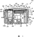
Fig. 1 is the section-drawing of the gas generator P1 of embodiments of the invention 1.
Fig. 2 is the section-drawing of the gas generator P2 of embodiments of the invention 2.
Fig. 3 is the section-drawing of the gas generator P3 of embodiments of the invention 3.
The specific embodiment
Below, the embodiment to gas generator of the present invention explains with reference to accompanying drawing.
Figure 1 shows that the section-drawing of the gas generator P1 of the embodiment of the invention 1.Among Fig. 1, gas generator P1 is the producer that driver's seat is launched with airbag inflation, and it is by constituting with the lower part: by causing the cylindric cover 3 that shell 1 and closure shell 2 constitute; Be located in the cover 3, form the cylinder element 5 of second combustion chamber 4; Be located at discoid second filtering installation 6 in this cylinder element 5; Along being provided with in interior week of cover 3, inside is formed with the first circular filtering installation 8 of first combustion chamber 7; The spacer member that axially limits 39 in the cover 3 to gas generator; Be seated in gas generant 14a, 14b in each combustion chamber 4,7; Be located at the ignition device 16,17 in each combustion chamber 4,7 respectively.To cause shell 1 and closure shell 2 is involutory, and engage with methods such as welding at 10 places, junction surface.Again, cause shell 1 and closure shell 2, also available method except welding, for example method such as pressure welding engages.
Constitute the closure shell 2 of cylindric cover 3, by top plate portion 11, from the side tube part 12 of top plate portion 11 to 1 extension of initiation shell, and the flange part 13 that extends to the diameter outside from side tube part 12 constitutes.Be formed with a plurality of gas discharge outlets 15 on the side tube part 12, be used to discharge the gas that is produced by gas generant 14a, 14b burning.On the gas discharge outlet 15, on the inside face of side tube part 12, be pasted with fracture (rupture) members 18 such as aluminium strip.Like this, prevent that exterior moisture etc. from entering in the cover 3.
And initiation shell 1 that with methods such as welding, pressure weldings engage involutory with closure shell 2, by base plate 21, the side tube part 22 that extends to closure shell 2 from base plate 21 constitutes.Base plate 21 is provided with the cylindric ignition device maintaining part 23,24 that keeps ignition device 16,17.As the firing unit 38 of the component parts of ignition device 16 and ignition device described later 17, riveted and fixed is on these ignition device maintaining parts 23,24 respectively.Here said ignition device, be meant situation about only constituting by the firing unit that is used to catch fire from the energising of controlling device, perhaps, also can comprise on this basis, strengthen (enhancer) agent and container thereof etc. and be configured in the gas generator in-to-in for gas generant is caught fire really.
Along by this closure shell 2 with cause first filtering installation 8 that the internal perisporium face of the side tube part 22,12 of the cover 3 that shell 1 constitutes is provided with, be configured as for example complex of knitting wire gauze, plain weave wire gauze and tuck weave metal wire rod cylindric, thus, can make at an easy rate.Preferably, can carry out drawing, can be made into arbitrary shape with knitting wire gauze.On the periphery of this first filtering installation 8, the cover 3 lower side, be formed with protuberance 25.Like this, protuberance 25 contacts with the internal perisporium face of the side tube part 22 that causes shell 1, can position reliably in cover 3.And protuberance 25 always contacts with causing shell 1, so can prevent the burning gases shunting from first combustion chamber.By protuberance 25, between cover 3 the inwall and first filtering installation 8, form space 26 again.Like this, owing to be formed with space 26, just stop, mix from the gas of each first combustion chamber 7 described later and second combustion chamber 4, then from gas discharge outlet 15 dischargings in this space 26.
The inner space of this first filtering installation 8 is divided into the cylinder element that bottom tube-like is arranged 5 of 2 chambers, is arranged to be covered with the form of 1 ignition device 16, this ignition device is located on the base plate 21 that causes shell 1 prejudicially.Cylinder element 5 is fixed on the initiation shell 1 with any means such as pressure welding, welding, riveted joints.And inner filling gas generant 14a constitutes second combustion chamber 4.
Form porosely 31 on the bottom 30 of this cylinder element 5, and be provided with orifice plate 32 and cover this hole 31 with a plurality of holes 33.This orifice plate 32 is fixed on any means such as riveted joints on the bottom 30 of cylinder element 5.6 supportings of discoid second filtering installation are arranged on the board member 34 of basket shape, so that contact with this orifice plate 32.Be located at a plurality of holes 33 on the orifice plate 32, with fracture member 35 sealings such as aluminium strips.The external and internal pressure difference of the fracture member 35 that is produced during for the igniting earlier of the gas generant 14b in first combustion chamber 7, discoid second filtering installation 6 becomes the tension member of fracture member 35, therefore, even fracture member 35 is littler than the component strength of prior art, also can seal reliably.
In the cover 3, be spaced apart member 39 gas generator axially on limit, and be divided into top and the bottom, form first combustion chamber 7 at the outer peripheral portion of above-mentioned second combustion chamber 4.
Be located at the ignition device 17 in first combustion chamber 7, be filled with the cylindrical duct that bottom tube-like is arranged 37 of starting mix 36 and the firing unit 38 that is used to light a fire from the energising of control part constitutes by inside.Cylindrical duct 37 is provided with ignition hole 45, is used for starting mix 36 igniting, burned flame to 7 ejections of first combustion chamber.Here said starting mix 36 is so long as the starting mix of energy usefulness all can use usually.Be filled with gas generant 14b in this first combustion chamber 7.
The gas generator P1 of present embodiment is provided with shunting in the bottom of spacer member 39 and prevents member 9, is used to prevent that the end face from this spacer member 39 from flowing into burning gases to the bottom of spacer member 39.
The gas generator P1 of present embodiment above-mentionedly constitutes like that, and second combustion chamber 4 and first combustion chamber 7 are not communicated with, and each combustion chamber is independent separately.Therefore, the gas that each combustion chamber produced does not flow into another combustion chamber under the situation of filtering, cooling off.
Above-mentioned such gas generator P1 that constitutes is assembled in the air bag component that is installed in the bearing circle.Each ignition device 16,17 of gas generator P1 is connected with the graphic vehicle side adaptor union of omission respectively, thereby is connected with control part.
Control part by for example detecting the crash sensor (acceleration pick-up) that auto against is used, to boost pressure circuit, spare capacitor and igniter (firing unit) the driving circuit formation of each ignition device 16,17 energising, is controlled with micro computer.
Detect automobile when bumping at crash sensor, with control part bonded assembly gas generator P1, at first, ignition device by igniting usefulness, for example the component parts with ignition device 17 is that firing unit 38 bonded assemblys are ignited driving circuit, only make ignition device 17 actions (energising igniting) that the gas generant 14b in first combustion chamber 7 is burnt, produce high-temperature gas.The gas that first combustion chamber 7 produces flows in first filtering installation 8, through cold filtration, discharges from gas discharge outlet 15 via space 26.In this stage, has only the gas generant 14b burning of first combustion chamber 7, so air bag begins the expansion of expanding lentamente.
Then, after the beginning of combustion of first combustion chamber 7, by the igniter driving circuit of controlling by the micro computer of control part, with the action (energising igniting) of small time official post ignition device 16.Then, make the gas generant 14a burning in second combustion chamber 4, thereby produce high-temperature gas.
The high-temperature gas that produces in second combustion chamber 4 flows in discoid second filtering installation 6, carries out cold filtration, flows out in the space 40 from hole 33 again.Flow out to the gas in the space 40,, discharge from gas discharge outlet 15 via space 26 by being formed at the recess 44 on the spacer member 39.Here, after flowing out to the gas in space 26 and gas from first combustion chamber 7 mixing, from gas discharge outlet 15 dischargings.So air bag is because of the expansion of promptly expanding of a large amount of clean airs of combustion chamber 4,7 discharging.
The action of each ignition device 16,17 is to describe with the form that at first makes ignition device 17 actions, still, also can make ignition device 16 action earlier, and, not necessarily need move with the small time difference, can suitably select according to the forms of collision of automobile.Even under the situation that at first makes ignition device 16 actions, the gas that second combustion chamber 4 is produced also can pass through cold filtration, and flows directly in first combustion chamber 7.
Like this, because combustion chamber 4,7 is independent separately, so be seated in each combustion chamber 4,7 the gas flow difference that each combustion chamber 4,7 is produced at for example identical or different gas generant 14a, the 14b of composition.Again, diameter by adjusting hole 33 and quantity etc., the various characteristics when also may command gas produces.In addition, because combustion chamber 4,7 is independent separately, so, just can according to circumstances control the form of the expansion expansion of air bag by to controlling the opening time that is located at the ignition device 10,17 in each combustion chamber 4,7.
For example, when resembling the high collision of the degree of risk of at full speed carrying out head-on crash or the frontal collisions, each ignition device 16,17 is moved (energising igniting) simultaneously, a large amount of gases that each combustion chamber 4,7 produces make the air bag expansion of expanding rapidly.Again, when degree of risk is moderate collision, make firing unit 16,17 with small time difference action (energising igniting), make the air bag expansion of expanding lentamente at the expansion initial stage with a spot of gas, after the very short time, with the expansion of expanding rapidly of a large amount of gas.The collision that degree of risk is little for example makes ignition device 16 or 17 actions (energising igniting), and long time of cost makes the air bag expansion of expanding lentamente with a spot of gas.
Below, Figure 2 shows that the section-drawing of the gas generator P2 of the embodiment of the invention 2.Among Fig. 2, the same mark of the member identical, and detailed with Fig. 1.
Gas generator P2 among Fig. 2 is different with the gas generator P1 of the foregoing description 1, the top plate portion 11 ground settings of first filtering installation 8 from the base plate 21 that causes shell 1 to closure shell 2.Therefore, from second combustion chamber, 4 effluent airs, at first through after second filtering installation 6 that in cylinder element 5, is provided with, again by first filtering installation 8.
In the gas generator P2 of present embodiment, the end bent of spacer member 39, each end contacts with first filtering installation 8 and cylinder element 5 respectively, so can prevent the burning gases shunting.
Figure 3 shows that the section-drawing of the gas generator P3 of the embodiment of the invention 3.Among Fig. 3, the same mark of the member identical, and detailed with Fig. 1.
The gas generator P3 of Fig. 3, P2 is different with aforesaid gas generator, discoid filtering installation 6 is different with Fig. 1 and Fig. 2, not to be seated in the cylinder element 5 (seeing Fig. 1, Fig. 2), but the cylinder element 5 that inner cylindrical tube 41 replaces Fig. 1 and Fig. 2 is set, the inside that porose 43 the inner bobbin that bottom tube-like is arranged 42 is located at inner cylindrical tube 41 is formed on the bottom.Like this, can reduce amount of parts, but simplified construction.And, also can utilize inner bobbin 42 to prevent to shunt from the burning gases of filtering installation end face.
Industrial applicibility
Gas generator of the present invention consists of as described above, and amount of parts is few, the combustion chamber Can be divided into more than 2, each combustion chamber is not communicated with really, can be separately independent. At least 1 combustion Burn the chamber and use discoid filter, thus filter can be made at low cost, and can be easy Assembling gas generator in ground is so can reduce significantly manufacturing cost.
Claims (9)
1. gas generator, it comprises with the lower part: the cover cylindraceous (3) that is made of initiation shell (1) with a plurality of ignition devices (16,17) and closure shell (2);
Be formed in the above-mentioned cover (3) and be filled with the combustion chamber of gas generant (14a, 14b);
Above-mentioned combustion chamber is divided into the cylinder element (5) of 2 combustion chambers (4,7) more than the chamber;
Be arranged on the filtering installation (6,8) that is divided in above each combustion chamber (4,7) in above-mentioned 2 chambers,
Above-mentioned each combustion chamber (4,7) is independent separately,
It is characterized in that at least 1 of above-mentioned filtering installation (6,8) is discoid.
2. gas generator as claimed in claim 1, at least 1 chamber in the above-mentioned combustion chamber (4,7) by spacer member (39) gas generator axially on limit.
3. gas generator as claimed in claim 1 is provided with the orifice plate (32) with a plurality of holes (33) in above-mentioned cylinder element (5).
4. gas generator as claimed in claim 1, at least 1 chamber in the above-mentioned combustion chamber (4,7) by spacer member (39) gas generator axially on limit, and, in above-mentioned cylinder element (5), be provided with orifice plate (32) with a plurality of holes (33).
5. gas generator as claimed in claim 1 has formed a plurality of holes (33) on the bottom (30) of above-mentioned cylinder element (5).
6. gas generator as claimed in claim 1, at least 1 chamber in the above-mentioned combustion chamber (4,7) by spacer member (39) gas generator axially on limit, and, on the bottom (30) of above-mentioned cylinder element (5), formed a plurality of holes (33).
7. gas generator as claimed in claim 2, above-mentioned spacer member (39) is configured as corrugated plate shape, to prevent to be out of shape and to guarantee the stream of gas in above-mentioned cylinder element (5) that combustion chamber is produced.
8. gas generator as claimed in claim 4, above-mentioned spacer member (39) is configured as corrugated plate shape, to prevent to be out of shape and to guarantee the stream of gas in above-mentioned cylinder element (5) that combustion chamber is produced.
9. gas generator as claimed in claim 6, above-mentioned spacer member (39) is configured as corrugated plate shape, to prevent to be out of shape and to guarantee the stream of gas in above-mentioned cylinder element (5) that combustion chamber is produced.
Applications Claiming Priority (2)
| Application Number | Priority Date | Filing Date | Title |
|---|---|---|---|
| JP2002045640 | 2002-02-22 | ||
| JP45640/2002 | 2002-02-22 |
Publications (2)
| Publication Number | Publication Date |
|---|---|
| CN1635963A CN1635963A (en) | 2005-07-06 |
| CN1328091C true CN1328091C (en) | 2007-07-25 |
Family
ID=27750588
Family Applications (1)
| Application Number | Title | Priority Date | Filing Date |
|---|---|---|---|
| CNB038043602A Expired - Fee Related CN1328091C (en) | 2002-02-22 | 2003-02-21 | Gas generator |
Country Status (8)
| Country | Link |
|---|---|
| US (1) | US7404573B2 (en) |
| EP (1) | EP1477375B1 (en) |
| JP (1) | JP4079329B2 (en) |
| CN (1) | CN1328091C (en) |
| AU (1) | AU2003211244A1 (en) |
| DE (1) | DE60302554T2 (en) |
| PL (1) | PL208091B1 (en) |
| WO (1) | WO2003070528A1 (en) |
Families Citing this family (13)
| Publication number | Priority date | Publication date | Assignee | Title |
|---|---|---|---|---|
| ATE360560T1 (en) * | 2004-12-08 | 2007-05-15 | Delphi Tech Inc | GAS GENERATOR |
| EP1669259B1 (en) | 2004-12-08 | 2011-06-15 | Delphi Technologies, Inc. | Gas generator |
| US7487995B2 (en) * | 2005-03-10 | 2009-02-10 | Daicel Chemical Industries, Ltd. | Gas generator for air bag |
| US7503581B2 (en) * | 2006-03-22 | 2009-03-17 | Daicel Chemical Industries, Ltd. | Gas generator for occupant restraining device for vehicle |
| ATE470603T1 (en) * | 2008-04-02 | 2010-06-15 | Delphi Tech Inc | HOUSING ARRANGEMENT FOR A GAS GENERATOR |
| US20120234193A1 (en) | 2011-03-17 | 2012-09-20 | Special Devices, Inc. | Igniter with a locked consolidated powder charge |
| JP5763000B2 (en) * | 2012-03-19 | 2015-08-12 | 株式会社ダイセル | Gas generator |
| US8556294B1 (en) | 2012-08-22 | 2013-10-15 | Key Safety Systems, Inc | Airbag inflator |
| JP6563825B2 (en) * | 2015-02-09 | 2019-08-21 | 株式会社ダイセル | Gas generator |
| JP6543560B2 (en) * | 2015-11-26 | 2019-07-10 | 株式会社ダイセル | Gas generator |
| JP6633985B2 (en) * | 2016-07-20 | 2020-01-22 | 株式会社ダイセル | Gas generator |
| DE102018201510A1 (en) | 2018-02-01 | 2019-08-01 | Robert Bosch Gmbh | Device for transmitting a signal by means of waveguides |
| CN110228440A (en) * | 2019-06-25 | 2019-09-13 | 延锋汽车智能安全系统有限责任公司 | The quick-fried device module of point, gas generator and air bag |
Citations (5)
| Publication number | Priority date | Publication date | Assignee | Title |
|---|---|---|---|---|
| US6032979A (en) * | 1998-02-18 | 2000-03-07 | Autoliv Asp, Inc. | Adaptive output inflator |
| JP2000296756A (en) * | 1999-02-05 | 2000-10-24 | Nippon Kayaku Co Ltd | Gas generator |
| US6189927B1 (en) * | 1999-12-16 | 2001-02-20 | Autoliv Asp, Inc. | Adaptive output inflator |
| US6315322B1 (en) * | 1999-03-05 | 2001-11-13 | Trw Inc. | Air bag inflator |
| JP2001353438A (en) * | 2000-05-19 | 2001-12-25 | Takata Corp | Gas generator |
Family Cites Families (8)
| Publication number | Priority date | Publication date | Assignee | Title |
|---|---|---|---|---|
| US6474684B1 (en) * | 1997-04-24 | 2002-11-05 | Talley Defense Systems, Inc. | Dual stage inflator |
| JPH11263185A (en) | 1998-03-17 | 1999-09-28 | Takata Kk | Air bag inflator |
| US6929284B1 (en) | 1999-02-05 | 2005-08-16 | Nippon Kayaku Kabushiki-Kaisha | Gas generator |
| US6149193A (en) * | 1999-08-06 | 2000-11-21 | Breed Automotive Technology, Inc. | Variable output inflator |
| DE29920123U1 (en) | 1999-11-16 | 2000-03-23 | Trw Airbag Sys Gmbh & Co Kg | Multi-stage gas generator |
| WO2001068415A1 (en) * | 2000-03-13 | 2001-09-20 | Nippon Kayaku Kabushiki-Kaisha | Gas generator |
| JP2003089338A (en) * | 2000-10-31 | 2003-03-25 | Daicel Chem Ind Ltd | Gas generator for air bag and air bag system using the same |
| EP1354774A4 (en) * | 2000-12-26 | 2005-03-23 | Nippon Kayaku Kk | Gas generator |
-
2003
- 2003-02-21 EP EP03705380A patent/EP1477375B1/en not_active Expired - Fee Related
- 2003-02-21 CN CNB038043602A patent/CN1328091C/en not_active Expired - Fee Related
- 2003-02-21 JP JP2003569455A patent/JP4079329B2/en not_active Expired - Fee Related
- 2003-02-21 PL PL371117A patent/PL208091B1/en unknown
- 2003-02-21 AU AU2003211244A patent/AU2003211244A1/en not_active Abandoned
- 2003-02-21 US US10/502,705 patent/US7404573B2/en not_active Expired - Fee Related
- 2003-02-21 WO PCT/JP2003/001905 patent/WO2003070528A1/en active IP Right Grant
- 2003-02-21 DE DE60302554T patent/DE60302554T2/en not_active Expired - Lifetime
Patent Citations (6)
| Publication number | Priority date | Publication date | Assignee | Title |
|---|---|---|---|---|
| US6032979A (en) * | 1998-02-18 | 2000-03-07 | Autoliv Asp, Inc. | Adaptive output inflator |
| US6032979C1 (en) * | 1998-02-18 | 2001-10-16 | Autoliv Asp Inc | Adaptive output inflator |
| JP2000296756A (en) * | 1999-02-05 | 2000-10-24 | Nippon Kayaku Co Ltd | Gas generator |
| US6315322B1 (en) * | 1999-03-05 | 2001-11-13 | Trw Inc. | Air bag inflator |
| US6189927B1 (en) * | 1999-12-16 | 2001-02-20 | Autoliv Asp, Inc. | Adaptive output inflator |
| JP2001353438A (en) * | 2000-05-19 | 2001-12-25 | Takata Corp | Gas generator |
Also Published As
| Publication number | Publication date |
|---|---|
| AU2003211244A1 (en) | 2003-09-09 |
| PL371117A1 (en) | 2005-06-13 |
| JPWO2003070528A1 (en) | 2005-06-09 |
| CN1635963A (en) | 2005-07-06 |
| DE60302554D1 (en) | 2006-01-05 |
| JP4079329B2 (en) | 2008-04-23 |
| EP1477375A4 (en) | 2005-04-06 |
| US20050052006A1 (en) | 2005-03-10 |
| EP1477375B1 (en) | 2005-11-30 |
| DE60302554T2 (en) | 2006-08-10 |
| EP1477375A1 (en) | 2004-11-17 |
| PL208091B1 (en) | 2011-03-31 |
| US7404573B2 (en) | 2008-07-29 |
| WO2003070528A1 (en) | 2003-08-28 |
Similar Documents
| Publication | Publication Date | Title |
|---|---|---|
| US6485051B1 (en) | Gas generator | |
| US7441803B2 (en) | Gas generator for air bag, deflecting member, coolant/filter means supporting member, coolant and housing | |
| KR100589993B1 (en) | Dual stage pyrotechnic airbag inflator | |
| US5628528A (en) | Dual chamber nonazide gas generator | |
| CN1328091C (en) | Gas generator | |
| US7152874B2 (en) | Gas generator for air bag and air bag apparatus | |
| US6695345B2 (en) | Airbag inflator and an airbag apparatus | |
| US7055855B2 (en) | Gas generator for multi-stage air bag | |
| EP1331143B1 (en) | Gas generator for air bag and air bag device | |
| US7178831B2 (en) | Gas generator | |
| WO2000046078A1 (en) | Gas generator | |
| JP3781603B2 (en) | Gas generator | |
| US7520530B2 (en) | Gas generator for air bag | |
| CN101835662A (en) | Air-flow is the dual stage cylindrical inflator of axial flow from outside to inside | |
| JPH11217055A (en) | Gas generator | |
| WO2001068415A1 (en) | Gas generator | |
| KR20030010683A (en) | Gas generator | |
| JP2004359031A (en) | Multi-stage igniting type gas generator | |
| JPH11157412A (en) | Gas generator | |
| JP2001151071A (en) | Gas generator for air bag, and air bag device | |
| WO2000027673A1 (en) | Gas generator |
Legal Events
| Date | Code | Title | Description |
|---|---|---|---|
| C06 | Publication | ||
| PB01 | Publication | ||
| C10 | Entry into substantive examination | ||
| SE01 | Entry into force of request for substantive examination | ||
| C14 | Grant of patent or utility model | ||
| GR01 | Patent grant | ||
| C17 | Cessation of patent right | ||
| CF01 | Termination of patent right due to non-payment of annual fee |
Granted publication date: 20070725 Termination date: 20140221 |