CN1327947C - Flow distributor for an alkylation reactor or heat exchanger - Google Patents
Flow distributor for an alkylation reactor or heat exchanger Download PDFInfo
- Publication number
- CN1327947C CN1327947C CNB03808581XA CN03808581A CN1327947C CN 1327947 C CN1327947 C CN 1327947C CN B03808581X A CNB03808581X A CN B03808581XA CN 03808581 A CN03808581 A CN 03808581A CN 1327947 C CN1327947 C CN 1327947C
- Authority
- CN
- China
- Prior art keywords
- mentioned
- flow distributor
- entrance side
- tube sheet
- channel head
- Prior art date
- Legal status (The legal status is an assumption and is not a legal conclusion. Google has not performed a legal analysis and makes no representation as to the accuracy of the status listed.)
- Expired - Fee Related
Links
Images


Classifications
-
- F—MECHANICAL ENGINEERING; LIGHTING; HEATING; WEAPONS; BLASTING
- F28—HEAT EXCHANGE IN GENERAL
- F28F—DETAILS OF HEAT-EXCHANGE AND HEAT-TRANSFER APPARATUS, OF GENERAL APPLICATION
- F28F9/00—Casings; Header boxes; Auxiliary supports for elements; Auxiliary members within casings
- F28F9/02—Header boxes; End plates
- F28F9/026—Header boxes; End plates with static flow control means, e.g. with means for uniformly distributing heat exchange media into conduits
- F28F9/0265—Header boxes; End plates with static flow control means, e.g. with means for uniformly distributing heat exchange media into conduits by using guiding means or impingement means inside the header box
-
- B—PERFORMING OPERATIONS; TRANSPORTING
- B01—PHYSICAL OR CHEMICAL PROCESSES OR APPARATUS IN GENERAL
- B01J—CHEMICAL OR PHYSICAL PROCESSES, e.g. CATALYSIS OR COLLOID CHEMISTRY; THEIR RELEVANT APPARATUS
- B01J19/00—Chemical, physical or physico-chemical processes in general; Their relevant apparatus
- B01J19/0053—Details of the reactor
-
- B—PERFORMING OPERATIONS; TRANSPORTING
- B01—PHYSICAL OR CHEMICAL PROCESSES OR APPARATUS IN GENERAL
- B01J—CHEMICAL OR PHYSICAL PROCESSES, e.g. CATALYSIS OR COLLOID CHEMISTRY; THEIR RELEVANT APPARATUS
- B01J19/00—Chemical, physical or physico-chemical processes in general; Their relevant apparatus
- B01J19/18—Stationary reactors having moving elements inside
-
- C—CHEMISTRY; METALLURGY
- C07—ORGANIC CHEMISTRY
- C07C—ACYCLIC OR CARBOCYCLIC COMPOUNDS
- C07C2/00—Preparation of hydrocarbons from hydrocarbons containing a smaller number of carbon atoms
- C07C2/54—Preparation of hydrocarbons from hydrocarbons containing a smaller number of carbon atoms by addition of unsaturated hydrocarbons to saturated hydrocarbons or to hydrocarbons containing a six-membered aromatic ring with no unsaturation outside the aromatic ring
- C07C2/56—Addition to acyclic hydrocarbons
- C07C2/58—Catalytic processes
- C07C2/62—Catalytic processes with acids
-
- F—MECHANICAL ENGINEERING; LIGHTING; HEATING; WEAPONS; BLASTING
- F28—HEAT EXCHANGE IN GENERAL
- F28D—HEAT-EXCHANGE APPARATUS, NOT PROVIDED FOR IN ANOTHER SUBCLASS, IN WHICH THE HEAT-EXCHANGE MEDIA DO NOT COME INTO DIRECT CONTACT
- F28D7/00—Heat-exchange apparatus having stationary tubular conduit assemblies for both heat-exchange media, the media being in contact with different sides of a conduit wall
- F28D7/06—Heat-exchange apparatus having stationary tubular conduit assemblies for both heat-exchange media, the media being in contact with different sides of a conduit wall the conduits having a single U-bend
-
- F—MECHANICAL ENGINEERING; LIGHTING; HEATING; WEAPONS; BLASTING
- F28—HEAT EXCHANGE IN GENERAL
- F28F—DETAILS OF HEAT-EXCHANGE AND HEAT-TRANSFER APPARATUS, OF GENERAL APPLICATION
- F28F27/00—Control arrangements or safety devices specially adapted for heat-exchange or heat-transfer apparatus
- F28F27/02—Control arrangements or safety devices specially adapted for heat-exchange or heat-transfer apparatus for controlling the distribution of heat-exchange media between different channels
-
- B—PERFORMING OPERATIONS; TRANSPORTING
- B01—PHYSICAL OR CHEMICAL PROCESSES OR APPARATUS IN GENERAL
- B01J—CHEMICAL OR PHYSICAL PROCESSES, e.g. CATALYSIS OR COLLOID CHEMISTRY; THEIR RELEVANT APPARATUS
- B01J2219/00—Chemical, physical or physico-chemical processes in general; Their relevant apparatus
- B01J2219/00049—Controlling or regulating processes
- B01J2219/00051—Controlling the temperature
- B01J2219/00074—Controlling the temperature by indirect heating or cooling employing heat exchange fluids
- B01J2219/00076—Controlling the temperature by indirect heating or cooling employing heat exchange fluids with heat exchange elements inside the reactor
- B01J2219/00081—Tubes
-
- B—PERFORMING OPERATIONS; TRANSPORTING
- B01—PHYSICAL OR CHEMICAL PROCESSES OR APPARATUS IN GENERAL
- B01J—CHEMICAL OR PHYSICAL PROCESSES, e.g. CATALYSIS OR COLLOID CHEMISTRY; THEIR RELEVANT APPARATUS
- B01J2219/00—Chemical, physical or physico-chemical processes in general; Their relevant apparatus
- B01J2219/00049—Controlling or regulating processes
- B01J2219/00051—Controlling the temperature
- B01J2219/00074—Controlling the temperature by indirect heating or cooling employing heat exchange fluids
- B01J2219/00105—Controlling the temperature by indirect heating or cooling employing heat exchange fluids part or all of the reactants being heated or cooled outside the reactor while recycling
- B01J2219/00108—Controlling the temperature by indirect heating or cooling employing heat exchange fluids part or all of the reactants being heated or cooled outside the reactor while recycling involving reactant vapours
-
- B—PERFORMING OPERATIONS; TRANSPORTING
- B01—PHYSICAL OR CHEMICAL PROCESSES OR APPARATUS IN GENERAL
- B01J—CHEMICAL OR PHYSICAL PROCESSES, e.g. CATALYSIS OR COLLOID CHEMISTRY; THEIR RELEVANT APPARATUS
- B01J2219/00—Chemical, physical or physico-chemical processes in general; Their relevant apparatus
- B01J2219/00049—Controlling or regulating processes
- B01J2219/00051—Controlling the temperature
- B01J2219/00074—Controlling the temperature by indirect heating or cooling employing heat exchange fluids
- B01J2219/00105—Controlling the temperature by indirect heating or cooling employing heat exchange fluids part or all of the reactants being heated or cooled outside the reactor while recycling
- B01J2219/0011—Controlling the temperature by indirect heating or cooling employing heat exchange fluids part or all of the reactants being heated or cooled outside the reactor while recycling involving reactant liquids
Abstract
The invention focuses on distributing the vapor/liquid flow that emerges from an inlet nozzle (23) across the tube sheet (24b) of an alkylation reactor or heat exchanger. The flow distributor (50) takes the two-phase flow that emerges from the inlet nozzle (23), turns it towards the tubesheet (4b) and delivers a uniform mixture across the tube sheet (24b). The flow distributor (50) is located in the channel head (24) of the reactor or heat exchanger. In order to dislodge the liquid film from the wall of the inlet nozzle (23), trip rings (52) and angular trip tabs are located internally in the flow distributor (50).
Description
Background of invention
Invention field
The present invention relates to flow distributor, described flow distributor is used for increasing the distribution of alkylation reactors channel head reactor hydrocarbon stream fluid, so that improve reactor refrigeration and pipeline is stained and corrosion reduces to minimum.In the ordinary course of things, the liquid that the present invention can be used for improving in any heat exchanger channel head distributes, and above-mentioned heat exchanger has a kind of combined liquid/vapor stream of admission passage head.
Description of Related Art
In alkanisation, iso-butane reacts with the light olefin class in the presence of sulfuric acid or hydrofluoric acid emulsion.According to the carbon number and the isomers structure of olefin hydrocarbon molecules, it is in up to 80 '-100 scopes that a kind of side chain isoparaffin produces its octane number.In sulfuric acid process, reaction is normally carried out under 4.4 ℃ (40 )-10 ℃ (50 ), requires refrigeration simultaneously.
The method schematic diagram that person skilled in art shown in Fig. 1 is known, liquid phase olefin class 10 and iso-butane 12 are sent into reactor 14 continuously under about 4.4 ℃ (40 ) temperature herein.A kind of emulsion that immiscible hydro carbons and sulfuric acid constitute forms by a kind of mixing impeller 16 in reactor 14.Impeller 16 also makes emulsion cross some cooling tube (not shown) circulations in reactor 14.Emulsion is forced to upwards arrive a settler 18 from reactor 14 by pipeline 17, is separated at these settler 18 place's hydrocarbon phases and acid.Acid relies on gravity by pipeline 20 Returning reactors 14 then.Contain dynamic alkylates (motor alkylate) in the hydrocarbon phase, excessive iso-butane, propane and normal butane, above-mentioned hydrocarbon phase is put into a flash valve 22 by pipeline 19 and changes in the inlet nozzle 23 of channel head 24 of reactor 14 from settler 18.From the inlet nozzle 23 of channel head 24, hydrocarbon vapours and liquid flow through tube bank 26 (see figure 2)s, and discharge by outlet nozzle 25, and above-mentioned tube bank 26 can comprise such as 300-1000+U shape manages.When the reactor stream fluid flow through each U-shaped pipe, excessive iso-butane and light hydrocarbons evaporated, thereby provided refrigeration to process.Reactor stream fluid 30 arrives a flash drum 32.The steam that comes out from flash drum 32 is compressed compressor 34, and passes cooler 36 and deliver to separator 37 by pipeline 37a then.The rich propane stream 37c that comes out from separator 37 carries out fractionation depropanizing tower 38, emit LPG (liquefied petroleum gas) product stream 38a simultaneously from device.The liquid that comes out from flash drum 32 flows 35a fractionation deisobutanizer 35.Bottom alkylates 35c separating device, and normally send to and carry out gasoline concoction.The side draw stream 35b of normal butane is separating device also.Rich isobutane stream 37b in the overhead that is rich in unreacted iso-butane stream 35d and the separator 37 and the liquid in the depropanizing tower 38 flow 38b and combine, and are recycled to reactor 14.
The industry standard design that is used for a kind of alkylation reactors tube bundle assembly can comprise hundreds of U-shaped pipe.It is a kind of that to have the typical channel head 24 of managing assembly 26 shown in Figure 2.A dividing plate 24a in the channel head 24 is separated into an entrance side 23a and an outlet side 25a with channel head.The reactor effluent vapor/liquid stream that comes out from flash valve 22 passes through the entrance side 23a of inlet nozzle 23 admission passage heads 24.Several major defects are arranged under this design conditions.Two phase flow, because it has begun flash distillation and will impact on dividing plate 24a with the entrance side 23a of reasonably high-speed admission passage head 24.Do not provide and will enter circulation to tube sheet 24b, tube bank 26 is installed on the above-mentioned tube sheet 24b.Part liquid stream will bend towards the plurality of U-shaped pipe arrival end of (comprising tube bank 26), and above-mentioned U-shaped pipe is fixed on the tube sheet 24b, and a part of liquid stream will flow into half elliptic channel head 24 away from tube sheet.The liquid stream that is recycled to channel head 24 entrance side 23a will eddy backward, pass through around the inlet jet (coming out from inlet nozzle 23) that rises, and enter and be positioned at tube bank 26 outside or peripheral plurality of U-shaped pipes.Because density of liquid phase is more much bigger than vapor phase,, perhaps will impact on dividing plate 24a so big quantity of fluid will turn to the middle part of each inlet tube of tube sheet 24b.Eddy backward and to flow through the outside steam of tube bank 26 each pipe not enough liquid from the entrance side 23a of channel head 24, and therefore greatly reduce heat transmission.Industry experience shows, generally is externally to observe in the pipe with staining the problem relevant with tube leaks, and it is irregular to meet flow distribution simultaneously.
Also reported the invention that comprises inner vanes in document (seeing United States Patent (USP) 5,531,266,5,625,112 and 5,811,625), above-mentioned blade will enter liquid stream and be divided into a plurality of liquid streams.
Also reported by will enter liquid stream with the cluster narrow tube to be divided into a plurality of liquid streams, above-mentioned cluster narrow tube is placed in the channel head inside of reactor.
Utilize flow distributor as described herein to improve refrigeration and increase the tube bank life-span and in open source literature, do not appear in the newspapers by making corrosion in the alkylation method reduce to minimum.
This same device can be used for improving the distribution of liquid on the heat exchanger channel head tube sheet of any like configurations in the two-phase inlet stream.When hope at various shell and tube heat exchangers such as fixed tube sheet, U-shaped pipe, during the liquid distillate that floats in any evenly vaporization first-class and enter, the present invention will promote above-mentioned even distribution.Evenly distribution will increase the vaporization and the heat transmission of liquid in the heat exchanger.
Summary of the invention
In a kind of alkylation reactors, comprise a housing, described housing has a channel head, above-mentioned channel head has an inlet nozzle and an outlet nozzle, above-mentioned inlet nozzle and outlet nozzle are with a dividing plate separately, the tube sheet that above-mentioned housing is transversely installed is used for installing a plurality of U-shaped pipes thereon, wherein above-mentioned each pipe crosses the length of above-mentioned reactor shell from the entrance side of above-mentioned channel head, and forms the outlet side that U-shaped forwards above-mentioned channel head to, and improvement comprises:
A flow distributor is installed in the entrance side of above-mentioned channel head, be used on the entrance side of above-mentioned tube sheet, distributing equably any fluid that enters above-mentioned channel head entrance side, above-mentioned flow distributor has an entrance side, described entrance side is used for the inlet nozzle of the above-mentioned channel head entrance side of sealed encirclement, above-mentioned flow distributor is a kind of tubaeform conduit of dispersing, and described tubaeform conduit is suitable for the fluid of above-mentioned Way in is circulated to tube sheet and the input side that turns to above-mentioned pipeline.
Brief description
Fig. 1 is the schematic diagram of a kind of typical alkylation unit method flow diagram of prior art systems.
Fig. 2 is a kind of cutaway view of prior art alkylation reactors typical industry standard design.
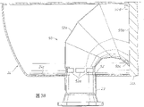
Fig. 3 A is the side elevation cutaway view according to a kind of flow distributor of the present invention.
Fig. 3 B is according to the alternative embodiment side elevation of a kind of flow distributor of the present invention cutaway view.
Fig. 4 A and Fig. 4 B are the cutaway views that releasing ring and inhalator window details are shown.
Fig. 5 A, 5B and 5C are the flow distributor front views that comprises releasing ring and angular trip bar.
Fig. 6 A, 6B and 6C illustrate rearview, front view and the top view of flow distributor among Fig. 3 respectively.
Fig. 7 is used for obtaining the tube sheet of table 1 data and the schematic diagram of pipe configuration.
Invention description
The shortcoming of above-mentioned industry standard design is the even distribution problem of mass flow discrepancy of not being devoted to cross tube sheet.Trend in the industry is by changing tube inlets with some metering holes, and above-mentioned metering hole will increase pressure drop.Although this will increase the liquid fraction in flowing, and perhaps increase drop size, it will improve flow distribution indistinctively.In fact, utilize tube insert industry trends may flow distribution is irregular to become poorer owing to causing liquid and vapor capacity to separate fully to make.
Do not resemble and not do not required by the invention reported in the patent right restriction, patent applicant's invention inlet flowed to be divided into multiple jets with inner vanes or baffler.Inner vanes and baffler must be welded on channel head inside, and therefore, the inlet nozzle of reactor easily take place to interrupt and hinder.The disclosed inlet device design of this article also can be widely used for improving generally to tube bundle assembly, comprising the flow distribution of heat exchanger.
Applicant's invention is at a kind of improvement of alkylation reactors well known in the prior art, and these reactors are sometimes referred to as contactor.One of major limitation is a temperature of reactor in alkanisation.Reduce temperature by the total heat transmission that increases from the emulsion to the reactor effluent, speed (and productive rate) will be increased greatly.
The vapor/liquid flow that total heat transfer rate is passed plurality of conduits is to a great extent joined the influence of degree, and above-mentioned plurality of conduits comprises tube bank.Fluid low is as externally, or at those pipelines of periphery, pipeline will have very low heat transfer rate as known in the art.Therefore, the liquid stream that crosses the skewness of tube bank will cause significantly reducing total heat transmission.Flowing of a kind of skewness, some pipeline seems minimal liquid and therefore hotter operation herein, also will cause quickening corrosive pipeline and the result causes tube leaks.The success experience that obtains from the alkanisation unit shows that tube leaks is the main cause that tube bundle assembly was stopped work and changed too early in the unit.
Invention disclosed herein is at a kind of method and apparatus that is used to receive steam/fluid stream, and above-mentioned vapor/liquid stream is discharged from inlet nozzle, and the entrance side that makes it cross tube sheet evenly distributes.This is by finishing with a kind of flow distributor 50 as shown in Figure 3A.Flow distributor 50 is connected on the inlet nozzle 23 of channel of reactor head, as shown in Fig. 3 A.Flow distributor 50 flushes on the inlet nozzle 23 that is welded to channel head 24, the internal cross section of flow distributor 50 is identical with the internal cross section of crooked funnel, and change continuously at its cross section towards the discharging of tube sheet 24b direction to tube sheet 24b (illustrate do not have connected tube bank 26) at the cross section of its porch from inlet nozzle 23, as shown in Fig. 3 A.The variation of cross-sectional area can be to measure stably or by several stages, as shown in Fig. 3 A.Flow distributor 50 receives the two-phase liquid stream of reactor stream fluid, and above-mentioned two-phase liquid stream is discharged from inlet nozzle 23, makes it rotate nearly 90 °, and makes it can disperse and a kind of homogeneous mixture conveying is crossed each inlet tube (not shown) of tube sheet 24b simultaneously.Keep a spacing 53 between the end face of flow distributor 50 and tube sheet 24b, above-mentioned spacing is approximately 1.5mm (1/16 ")-76.2mm (3 ").The steam of horn mouth inside and liquid needs this spacing 53, so that can be communicated with the remainder of channel head 24.The part of this connection occasion is to make liquid not enter pipeline to treat to suck by plurality of windows 52a and collect, above-mentioned suck below one section by plurality of windows 52a in explanation.In an alternative embodiment, shown in Fig. 3 b, the end face 50b of flow distributor 50 can paste tube sheet 24b placed flush.In this embodiment, need in flow distributor 50, lay plurality of rows discharge hole 50c and/or port 50d, be used to discharge the liquid that does not enter each pipeline 26, and be used for steam and be communicated with the remainder of channel head.
Fluid stream by inlet nozzle 23 admission passage heads 24 is a kind of steam and mixtures of liquids, and a part of liquid exists as a kind of film along the internal diameter of inlet duct and nozzle 23 simultaneously.A releasing ring 52 is installed in the porch of flow distributor 50, shown in Fig. 3 A and 3B, and in more detail shown in Fig. 4 A.Releasing ring 52 is removed fluid film, and helps film is dispersed as drop, and above-mentioned drop is conveyed through flow distributor 50 by steam subsequently.Along and the bottom (around circumference) of passing flow distributor 50 cut plurality of windows (or slit) 52a, as shown in Figure 4A and 4B.Each window 52a is located immediately at the downstream of releasing ring 52." venturi " effect of releasing ring 52 will accumulate in any liquid of channel head 24 bottom 24c by in the window 52a inhalation flow distributor 50, thereby further increase the distribution of liquid phase.
Referring now to Fig. 5 A-C,, when vapor/liquid mixture was rotated about 90 ° by the profile of distributor 50, a kind of fluid film began to launch on 50a inside, the top of flow distributor 50.An angular trip bar 54 that is arranged in distributor 50 tops is used for pulverizing this fluid film that produces drop, and has further improved flow distribution.
Fig. 5 A-C illustrates flow distributor 50, the situation of releasing ring 52 and release lever 54.Release lever 54 becomes an about 20-180 ° with flow direction, preferably 120 ° angle is installed on the top 50a of flow distributor 50.Release lever 54 is pulverized the fluid film on the top 50a of distributors 50, and has increased the uniformity of liquid distribution.Release lever 54 can comprise other embodiment, as bar being divided into some discrete segmentations, and separately each segmentation is installed on the 50a of top.In also having another embodiment, release lever also can be the zigzag with " groove " or " breach " of being cut into bar.
Fig. 6 A-C illustrates the rearview of distributor 50 respectively, and front view and top view.
Applicant's invention is compared with industrial standard, has improved the vapor/liquid flow of crossing each inlet tube in tube bank 26 of alkylation reactors greatly and has joined.Distribution is to pass inlet nozzle by the stream that prevents to enter the mouth to impact on the dividing plate 24a and finish.On the contrary, flow distributor 50 makes the inlet flow direction change about 90 °, and allows flow board expansion simultaneously, and makes it aim at the entrance side that crosses tube sheet 24a equably.Flow distributor 50 as herein described does not rely on the stream that will enter the mouth to split into a plurality of liquid streams comparably.Improved assignment of traffic will make reactor operate under a lower temperature, thereby increase production capacity and improved productivity ratio.In addition, better cross tube bank 26 flow uniformity and pipeline will be stained and corrosion reduces to minimum, and the result, expection increases the life-span of tube bundle assembly.
Above-mentioned flow distributor utilizes the simulation of detailed process calculation of Two Phase Flow machine and has carried out developmental research by a kind of scale (model) test of commercially available alkylation reactors channel head.
Fig. 7 illustrates a kind of tube sheet, and described tube sheet has the layout of beam line arrangement that is used for obtaining data in the table 1.Flow distributor 50 simulation admission passage heads 24 and the two-phase steam that crosses tube sheet/liquid stream to existing design (prior art) and new idea.See in the remarkable improvement of crossing on the assignment of traffic of tube bank with the present invention, as shown in table 1.The liquid that crosses tube sheet distributes by the liquid flow rate of coming out from the scaled model measurement from each pipeline to be determined.Scaled model comprises the conduit assembly of a kind of 48 pipelines of arranging as shown in Figure 7.Table 1 illustrates the flow rate of liquid of every discharge pipe, and the aforesaid liquid flow velocity is shown in total liquid percentage at the channel head place that enters the mouth.
Experimental result (seeing Table 1) shows, adopts a kind of as shown and described herein flow distributor 50, has improved the vapor/liquid flow of the inlet duct that crosses tube sheet 24b greatly and has joined.Applicant's invention is more effective, durable, and can and dangerously implement in existing alkylation reactors with cost seldom, especially because do not comprise blade and deflection plate.
Table 1
| Fluid flow [based on the % of total liquid] | ||
| Row of conduits | Applicant's invention | Prior art |
| A | 20.9 | 31.0 |
| B | 18.6 | 14.6 |
| C | 14.1 | 13.3 |
| D | 15.4 | 6.6 |
| E | 18.0 | 3.1 |
| F | 13.0 | 31.4 |
Claims (21)
1. alkylation reactors, comprise a housing, described housing has a channel head, above-mentioned channel head has an inlet nozzle and an outlet nozzle, and described inlet nozzle and outlet nozzle are separated by a dividing plate, and a tube sheet is installed transverse to above-mentioned housing, be used on housing, installing a plurality of U-shaped pipelines, wherein above-mentioned pipeline crosses the length of above-mentioned reactor shell from the entrance side of above-mentioned channel head, and forms the outlet side that the U-shaped bending forwards above-mentioned channel head to, and above-mentioned alkylation reactors also comprises:
A flow distributor, described flow distributor is installed in the entrance side of above-mentioned channel head, be used on the entrance side of above-mentioned tube sheet, distributing equably any fluid that enters above-mentioned channel head entrance side, above-mentioned flow distributor has an entrance side that is used for the inlet nozzle of the above-mentioned channel head entrance side of sealed encirclement, above-mentioned flow distributor is a kind of tubaeform conduit of dispersing, and described tubaeform conduit is suitable for above-mentioned fluid stream is turned to tube sheet and the input side that turns to above-mentioned pipeline from above-mentioned Way in.
2. device as claimed in claim 1, wherein above-mentioned tubaeform conduit and above-mentioned tube sheet are spaced apart.
3. device as claimed in claim 2 also comprises:
A releasing ring, described releasing ring is installed on the entrance side of above-mentioned flow distributor, is used to get rid of any liquid stream on the above-mentioned inlet nozzle inboard.
4. device as claimed in claim 3 also comprises:
A plurality of windows, described a plurality of windows directly center on above-mentioned flow distributor in the downstream of above-mentioned releasing ring circumference is inserted in the wall of above-mentioned flow distributor entrance side.
5. device as claimed in claim 4 also comprises:
A release lever, described release lever are installed to the inner surface top of above-mentioned flow distributor rigidly, are used to get rid of any fluid film that flows on the above-mentioned dispenser top.
6. device as claimed in claim 1, each input pipe of the above-mentioned tube sheet of the sealed encirclement of wherein above-mentioned tubaeform conduit.
7. device as claimed in claim 6 also comprises:
Some ports are so that provide being communicated with of steam or liquid and above-mentioned access road head remainder.
8. device as claimed in claim 7 also comprises:
A releasing ring, described releasing ring is installed on the entrance side of above-mentioned flow distributor, is used to get rid of any liquid stream on the above-mentioned inlet nozzle inboard.
9. device as claimed in claim 8 also comprises:
A plurality of windows, described a plurality of windows directly are inserted into the wall of above-mentioned flow distributor entrance side around the circumference of described flow distributor in the downstream of above-mentioned releasing ring.
10. device as claimed in claim 9 also comprises:
A release lever, described release lever is installed on the top of above-mentioned flow distributor inner surface rigidly, is used to get rid of any fluid film that flows on above-mentioned dispenser top.
11. heat exchanger, comprise a housing, described housing has a channel head, above-mentioned channel head has an inlet nozzle and an outlet nozzle, described inlet nozzle and outlet nozzle are separated by a dividing plate, and a tube sheet is used for installing a plurality of pipelines thereon installing transverse to above-mentioned housing, above-mentioned each pipeline crosses the length of above-mentioned reactor shell from the entrance side of above-mentioned channel head to the outlet side of above-mentioned channel head, above-mentioned heat exchanger also comprises:
A flow distributor, described flow distributor is installed in the entrance side of above-mentioned channel head, be used on the entrance side of above-mentioned tube sheet, distributing equably any fluid that enters above-mentioned channel head entrance side, above-mentioned flow distributor has an entrance side, the described inlet nozzle that is used for the above-mentioned channel head entrance side of sealed encirclement, above-mentioned flow distributor is a kind of tubaeform conduit of dispersing, and described tubaeform conduit is suitable for above-mentioned fluid stream is turned to tube sheet and turns on the input side of above-mentioned each pipeline from above-mentioned Way in.
12. device as claimed in claim 11, wherein above-mentioned tubaeform conduit and above-mentioned tube sheet are spaced apart.
13. device as claimed in claim 12 also comprises:
A releasing ring, described releasing ring is installed on the entrance side of above-mentioned flow distributor, is used to get rid of any liquid stream on the above-mentioned inlet nozzle inboard.
14. device as claimed in claim 13 also comprises:
Directly the circumference around flow distributor is inserted in the wall of above-mentioned flow distributor entrance side in above-mentioned releasing ring downstream for a plurality of windows, described each window.
15. device as claimed in claim 14 also comprises:
A release lever, described release lever are installed on the top, surface, inside of above-mentioned flow distributor rigidly, are used to get rid of any fluid film that flows on above-mentioned dispenser top.
16. device as claimed in claim 11, the above-mentioned tube sheet of the sealed encirclement of wherein above-mentioned tubaeform conduit.
17. device as claimed in claim 16 also comprises:
A releasing ring, described releasing ring is installed on the entrance side of above-mentioned flow distributor, is used to get rid of any liquid stream on above-mentioned inlet nozzle inboard.
18. device as claimed in claim 17 also comprises:
A plurality of windows, described a plurality of windows are inserted on the wall of above-mentioned flow distributor entrance side around flow distributor directly in the downstream of above-mentioned releasing ring.
19. device as claimed in claim 18 also comprises:
A release lever, described release lever are installed on the top on the inner surface of above-mentioned flow distributor, are used to get rid of any fluid film that flows on above-mentioned dispenser top.
20. a method, described method are used for crossing according to the tube sheet of any described alkylation reactors of claim 1-10 dispense liquid stream equably, said method may further comprise the steps:
A kind of liquid is flowed in the entrance side of the channel head of introducing a kind of alkylation reactors;
Reactor inlet side inside in above-mentioned channel head changes liquid flow direction with about 90 °;
Force liquid stream to be dispersed, change its flow direction simultaneously; And
Liquid stream is guided on the entrance side of a tube sheet equably.
21. a method, described method are used for crossing according to the tube sheet of any described heat exchanger of claim 11-19 dispense liquid stream equably, said method may further comprise the steps:
Liquid stream is introduced a kind of inlet of heat exchanger;
Change liquid flow direction in heat exchanger entrance inside with about 90 °;
Force liquid stream to be dispersed, and change its flow direction simultaneously; And
Liquid stream is guided on the entrance side of a tube sheet equably.
Applications Claiming Priority (2)
| Application Number | Priority Date | Filing Date | Title |
|---|---|---|---|
| US10/123,767 US6863121B2 (en) | 2002-04-16 | 2002-04-16 | Flow distributor for an alkylation reactor or heat exchanger |
| US10/123,767 | 2002-04-16 |
Publications (2)
| Publication Number | Publication Date |
|---|---|
| CN1646217A CN1646217A (en) | 2005-07-27 |
| CN1327947C true CN1327947C (en) | 2007-07-25 |
Family
ID=28790811
Family Applications (1)
| Application Number | Title | Priority Date | Filing Date |
|---|---|---|---|
| CNB03808581XA Expired - Fee Related CN1327947C (en) | 2002-04-16 | 2003-04-16 | Flow distributor for an alkylation reactor or heat exchanger |
Country Status (10)
| Country | Link |
|---|---|
| US (1) | US6863121B2 (en) |
| EP (1) | EP1506055A1 (en) |
| JP (1) | JP2005526884A (en) |
| KR (1) | KR20050060030A (en) |
| CN (1) | CN1327947C (en) |
| AU (1) | AU2003231529B2 (en) |
| CA (1) | CA2482925A1 (en) |
| EA (1) | EA006358B1 (en) |
| MX (1) | MXPA04010022A (en) |
| WO (1) | WO2003089134A1 (en) |
Families Citing this family (10)
| Publication number | Priority date | Publication date | Assignee | Title |
|---|---|---|---|---|
| CN101949663B (en) * | 2010-09-13 | 2011-09-28 | 三花丹佛斯(杭州)微通道换热器有限公司 | Refrigerant guide pipe and heat exchanger with same |
| CN101922883B (en) | 2010-09-13 | 2012-09-26 | 三花控股集团有限公司 | Refrigerant guide pipe and heat exchanger with same |
| US20140311466A1 (en) * | 2013-04-17 | 2014-10-23 | Caterpillar Inc. | Coolant Inlet Structures for Heat Exchangers for Exhaust Gas Recirculation Systems |
| US9580366B2 (en) | 2013-04-26 | 2017-02-28 | E I Du Pont De Nemours And Company | Continuous mixing reactor and method of use |
| CA2947321A1 (en) | 2014-05-02 | 2015-11-05 | Dana Canada Corporation | Manifold structure for re-directing a fluid stream |
| CN105588467B (en) * | 2016-03-01 | 2017-10-03 | 张家港富瑞重型装备有限公司 | Steam inlet device |
| EP3381531A1 (en) * | 2017-03-31 | 2018-10-03 | Vrije Universiteit Brussel | Flow distributor |
| US10486131B2 (en) | 2017-10-26 | 2019-11-26 | Chevron U.S.A. Inc. | Integrated reactor system for ionic liquid-catalyzed hydrocarbon conversion |
| CN108168339B (en) * | 2018-01-02 | 2023-11-07 | 珠海格力电器股份有限公司 | Shell-and-tube heat exchanger |
| CN114870662B (en) * | 2022-05-19 | 2023-08-08 | 北京永博洁净科技有限公司 | Flue gas mixer |
Citations (3)
| Publication number | Priority date | Publication date | Assignee | Title |
|---|---|---|---|---|
| US478003A (en) * | 1892-06-28 | Car-brake | ||
| FR1417821A (en) * | 1964-12-18 | 1965-11-12 | Foster Wheeler Corp | Bottom for heat exchanger |
| US5625112A (en) * | 1993-12-28 | 1997-04-29 | Uop | Method of indirect heat exchange for two phase flow distribution |
Family Cites Families (9)
| Publication number | Priority date | Publication date | Assignee | Title |
|---|---|---|---|---|
| NL128466C (en) * | 1964-03-07 | |||
| FR1332118A (en) * | 1964-04-16 | 1963-12-16 | ||
| US3374832A (en) * | 1966-05-13 | 1968-03-26 | Lummus Co | Inlet cone device and method |
| US4078292A (en) * | 1975-07-22 | 1978-03-14 | Allied Chemical Corporation | Transfer line exchanger inlet cone |
| NL182749C (en) * | 1979-01-30 | 1988-05-02 | Shell Int Research | HEAT EXCHANGER. |
| US4778003A (en) * | 1983-01-03 | 1988-10-18 | The Dow Chemical Company | Heat exchanger with novel seal for tube sheet |
| US5110560A (en) * | 1987-11-23 | 1992-05-05 | United Technologies Corporation | Convoluted diffuser |
| US5811625A (en) * | 1993-12-28 | 1998-09-22 | Uop Llc | Method of indirect heat exchange for two phase flow distribution |
| US6382313B2 (en) * | 2000-02-25 | 2002-05-07 | Nippon Shokubai Co., Ltd. | Heat exchanger for easily polymerizing substance-containing gas provided with gas distributing plate |
-
2002
- 2002-04-16 US US10/123,767 patent/US6863121B2/en not_active Expired - Fee Related
-
2003
- 2003-04-16 MX MXPA04010022A patent/MXPA04010022A/en not_active Application Discontinuation
- 2003-04-16 KR KR1020047016672A patent/KR20050060030A/en not_active Application Discontinuation
- 2003-04-16 JP JP2003585876A patent/JP2005526884A/en active Pending
- 2003-04-16 EP EP03726291A patent/EP1506055A1/en not_active Withdrawn
- 2003-04-16 AU AU2003231529A patent/AU2003231529B2/en not_active Ceased
- 2003-04-16 EA EA200401375A patent/EA006358B1/en not_active IP Right Cessation
- 2003-04-16 CN CNB03808581XA patent/CN1327947C/en not_active Expired - Fee Related
- 2003-04-16 WO PCT/US2003/011555 patent/WO2003089134A1/en not_active Application Discontinuation
- 2003-04-16 CA CA002482925A patent/CA2482925A1/en not_active Abandoned
Patent Citations (3)
| Publication number | Priority date | Publication date | Assignee | Title |
|---|---|---|---|---|
| US478003A (en) * | 1892-06-28 | Car-brake | ||
| FR1417821A (en) * | 1964-12-18 | 1965-11-12 | Foster Wheeler Corp | Bottom for heat exchanger |
| US5625112A (en) * | 1993-12-28 | 1997-04-29 | Uop | Method of indirect heat exchange for two phase flow distribution |
Also Published As
| Publication number | Publication date |
|---|---|
| AU2003231529B2 (en) | 2008-07-03 |
| JP2005526884A (en) | 2005-09-08 |
| WO2003089134A1 (en) | 2003-10-30 |
| AU2003231529A1 (en) | 2003-11-03 |
| EA200401375A1 (en) | 2005-08-25 |
| US20030192683A1 (en) | 2003-10-16 |
| US6863121B2 (en) | 2005-03-08 |
| CN1646217A (en) | 2005-07-27 |
| MXPA04010022A (en) | 2004-12-13 |
| EA006358B1 (en) | 2005-12-29 |
| KR20050060030A (en) | 2005-06-21 |
| CA2482925A1 (en) | 2003-10-30 |
| EP1506055A1 (en) | 2005-02-16 |
Similar Documents
| Publication | Publication Date | Title |
|---|---|---|
| CN1327947C (en) | Flow distributor for an alkylation reactor or heat exchanger | |
| EP2201085B1 (en) | Method and apparatus for cooling pyrolysis effluent | |
| JP6038019B2 (en) | Separation column section, separation column and operation method thereof | |
| BR112012008022B1 (en) | FLOW DISTRIBUTION DEVICE, AND, DISTRIBUTION TRAY | |
| BRPI0809348B1 (en) | MIXING DEVICE FOR TWO GASES / STEAMS AND PROCESS TO MIX TWO GASES / STEAMS | |
| US2920124A (en) | Alkylation of hydrocarbons with improved mixing and emulsifying of catalyst and reactants | |
| RU2459652C2 (en) | Method and device for making homogeneous vapor and liquid phases in two or more flows and method of cooling hydrocarbon flow | |
| US8235362B2 (en) | Fluid distribution to parallel flow vapor-liquid contacting trays | |
| EP0813582A1 (en) | Feed nozzle assembly | |
| US3284537A (en) | Method of charging reactants through concentric feed tubes | |
| CN103124593A (en) | Feed nozzle assembly | |
| US2302513A (en) | Heat exchanger and method of operation | |
| US7947232B2 (en) | HF alkylation reactor | |
| JP7102434B2 (en) | Heat exchanger with liquid / gas mixer with improved opening | |
| PT93233B (en) | DEVICE AND PROCESS FOR THE REDUCTION OF LIQUID SPILL, AND THE PROCESS OF AQUILACAO DE OLEFINAS USING THE DISCLOSURE DEVICE | |
| JP7258521B2 (en) | fluid distribution device | |
| US5811625A (en) | Method of indirect heat exchange for two phase flow distribution | |
| EP0106544B1 (en) | Distributor apparatus for fluid including a gaseous and liquid phase | |
| US9302952B2 (en) | Alkylation unit and process relating thereto | |
| US3527832A (en) | Coke prevention in steam cracking | |
| CN106606997B (en) | Upflow distributor and upflow reactor | |
| US6948453B1 (en) | Hydrocarbon cracking | |
| TW202333838A (en) | Simulated moving bed separation device and method with extended jet breaker | |
| JP2005272684A (en) | Method for operating sulfuric acid type alkylation apparatus | |
| NO175192B (en) |
Legal Events
| Date | Code | Title | Description |
|---|---|---|---|
| C06 | Publication | ||
| PB01 | Publication | ||
| C10 | Entry into substantive examination | ||
| SE01 | Entry into force of request for substantive examination | ||
| C14 | Grant of patent or utility model | ||
| GR01 | Patent grant | ||
| C17 | Cessation of patent right | ||
| CF01 | Termination of patent right due to non-payment of annual fee |
Granted publication date: 20070725 |