CN1325373C - Non-destructive separation of nanomorphic carbon species - Google Patents
Non-destructive separation of nanomorphic carbon species Download PDFInfo
- Publication number
- CN1325373C CN1325373C CNB038139936A CN03813993A CN1325373C CN 1325373 C CN1325373 C CN 1325373C CN B038139936 A CNB038139936 A CN B038139936A CN 03813993 A CN03813993 A CN 03813993A CN 1325373 C CN1325373 C CN 1325373C
- Authority
- CN
- China
- Prior art keywords
- carbon
- separating
- nanomorphic
- decanting
- steps
- Prior art date
- Legal status (The legal status is an assumption and is not a legal conclusion. Google has not performed a legal analysis and makes no representation as to the accuracy of the status listed.)
- Expired - Fee Related
Links
Images
Classifications
-
- B—PERFORMING OPERATIONS; TRANSPORTING
- B82—NANOTECHNOLOGY
- B82B—NANOSTRUCTURES FORMED BY MANIPULATION OF INDIVIDUAL ATOMS, MOLECULES, OR LIMITED COLLECTIONS OF ATOMS OR MOLECULES AS DISCRETE UNITS; MANUFACTURE OR TREATMENT THEREOF
- B82B3/00—Manufacture or treatment of nanostructures by manipulation of individual atoms or molecules, or limited collections of atoms or molecules as discrete units
-
- B—PERFORMING OPERATIONS; TRANSPORTING
- B82—NANOTECHNOLOGY
- B82Y—SPECIFIC USES OR APPLICATIONS OF NANOSTRUCTURES; MEASUREMENT OR ANALYSIS OF NANOSTRUCTURES; MANUFACTURE OR TREATMENT OF NANOSTRUCTURES
- B82Y30/00—Nanotechnology for materials or surface science, e.g. nanocomposites
-
- B—PERFORMING OPERATIONS; TRANSPORTING
- B82—NANOTECHNOLOGY
- B82Y—SPECIFIC USES OR APPLICATIONS OF NANOSTRUCTURES; MEASUREMENT OR ANALYSIS OF NANOSTRUCTURES; MANUFACTURE OR TREATMENT OF NANOSTRUCTURES
- B82Y40/00—Manufacture or treatment of nanostructures
-
- C—CHEMISTRY; METALLURGY
- C01—INORGANIC CHEMISTRY
- C01B—NON-METALLIC ELEMENTS; COMPOUNDS THEREOF; METALLOIDS OR COMPOUNDS THEREOF NOT COVERED BY SUBCLASS C01C
- C01B32/00—Carbon; Compounds thereof
- C01B32/05—Preparation or purification of carbon not covered by groups C01B32/15, C01B32/20, C01B32/25, C01B32/30
-
- C—CHEMISTRY; METALLURGY
- C01—INORGANIC CHEMISTRY
- C01B—NON-METALLIC ELEMENTS; COMPOUNDS THEREOF; METALLOIDS OR COMPOUNDS THEREOF NOT COVERED BY SUBCLASS C01C
- C01B32/00—Carbon; Compounds thereof
- C01B32/15—Nano-sized carbon materials
- C01B32/158—Carbon nanotubes
- C01B32/168—After-treatment
- C01B32/17—Purification
Landscapes
- Chemical & Material Sciences (AREA)
- Engineering & Computer Science (AREA)
- Nanotechnology (AREA)
- Organic Chemistry (AREA)
- Crystallography & Structural Chemistry (AREA)
- Materials Engineering (AREA)
- Inorganic Chemistry (AREA)
- Physics & Mathematics (AREA)
- Condensed Matter Physics & Semiconductors (AREA)
- General Physics & Mathematics (AREA)
- Manufacturing & Machinery (AREA)
- Composite Materials (AREA)
- Treatment Of Liquids With Adsorbents In General (AREA)
- Separation Of Solids By Using Liquids Or Pneumatic Power (AREA)
- Carbon And Carbon Compounds (AREA)
Abstract
Description
技术领域technical field
本发明总的来说涉及用于纳米形态碳分离的非化学反应性方法。更特别地,本发明涉及用于碳纳米管(CNT)和纳米纤维的纯化的非氧化性方法。The present invention generally relates to non-chemically reactive methods for the separation of nanomorphic carbon. More particularly, the present invention relates to non-oxidative methods for the purification of carbon nanotubes (CNTs) and nanofibers.
背景技术Background technique
自1970’s以来,石墨纳米管和细纤维已经被认为是对各种应用有价值的材料。亚微米石墨细纤维有时被称为气相生长碳纤维(例如,纳米纤维)。细碳纤维一般包括具有约小于1.0μm数量级的直径的蠕虫状碳沉积物,并典型地通过各种含碳气体在例如金属表面上催化裂解制备。由于电子显微镜学的出现,这些蠕虫状碳沉积物一般可以被观察到。参见例如Baker和Harris的“Chemistry and Physics of Carbon”,14,1978;以及N.Rodriguez,J.Material Research,8,1993。Since the 1970's, graphitic nanotubes and thin fibers have been recognized as valuable materials for a variety of applications. Submicron graphite fine fibers are sometimes referred to as vapor grown carbon fibers (eg, nanofibers). Fine carbon fibers generally comprise wormlike carbon deposits with diameters on the order of less than about 1.0 μm, and are typically produced by catalytic cracking of various carbon-containing gases on, for example, metal surfaces. These worm-like carbon deposits are generally observable thanks to the advent of electron microscopy. See, eg, Baker and Harris, "Chemistry and Physics of Carbon", 14, 1978; and N. Rodriguez, J. Material Research, 8, 1993.
1976年,Endo等人提出一种被认为是细碳纤维生长的基本机理。参见A.Obelin和M.J.Endo.的“Of Crystal Growth”,32,1976。细碳纤维一般首次被观察来自在烃类气体存在下与碳超饱和的金属催化颗粒。柱状排列的石墨芯被挤压,然后用热解沉积石墨外层包覆。这些细纤维典型地呈现0.1μm数量级的直径,更典型地在0.2至0.5μm之间。In 1976, Endo et al proposed a basic mechanism that is considered to be the growth of fine carbon fibers. See A. Obelin and M.J. Endo. "Of Crystal Growth", 32, 1976. Fine carbon fibers are generally first observed from metal-catalyzed particles supersaturated with carbon in the presence of hydrocarbon gases. A graphite core of columnar arrangement is extruded and then clad with an outer layer of pyrolytically deposited graphite. These fine fibers typically exhibit a diameter of the order of 0.1 μm, more typically between 0.2 and 0.5 μm.
1983年,Tennent成功地培育了普遍未被热解碳污染的柱状排列的石墨芯。参见例如专利号为4,663,230的美国专利。因此,Tennent一般提供了得到较小直径细纤维的捷径,典型地为35至700数量级(例如0.0035至0.070μm),以及一种有序的“生长态“石墨表面。一般也能观察到稍不规则结构(但无热解碳)的纤维状碳物质。In 1983, Tennent succeeded in growing a columnar array of graphite cores that were generally uncontaminated by pyrolytic carbon. See, eg, US Patent No. 4,663,230. Thus, Tennent generally provides a shortcut to smaller diameter fibrils, typically on the order of 35 to 700 Å (eg, 0.0035 to 0.070 μm), and an ordered "as grown" graphitic surface. Fibrous carbon substances with a slightly irregular structure (but no pyrolytic carbon) can also generally be observed.
细碳纤维、“巴基管“(例如,CNT)和纳米纤维一般与其它市售的作为例如加固材料的连续碳纤维不同。与通常具有较大纵横比但一般有限的细纤维相比,连续细碳纤维典型地呈现约104和常常达106或更大数量级的纵横比。连续碳纤维的直径一般也比细纤维的直径大得多;其通常大于约1.0μm,更典型地在5至7μm之间。与催化生长细纤维形态相似的碳纳米管被证实在较高温度碳弧中生长。参见例如:Lijima,Nature,354,56,1991。一般认为电弧生长纳米纤维具有基本上与由Tennent最初观察到的初期催化生长细纤维相似的形态。参见例如:Weaver,Science,265,1994。Fine carbon fibers, "bucky tubes" (eg, CNTs) and nanofibers are generally distinguished from other commercially available continuous carbon fibers as, for example, reinforcement materials. Continuous fine carbon fibers typically exhibit aspect ratios of the order of about 10 4 and often up to 10 6 or greater compared to fine fibers, which generally have larger aspect ratios but are generally limited. The diameter of continuous carbon fibers is also generally much larger than that of fine fibers; it is usually greater than about 1.0 μm, more typically between 5 and 7 μm. Carbon nanotubes with morphology similar to catalytically grown thin fibers were demonstrated to grow in a carbon arc at higher temperatures. See eg: Lijima, Nature, 354, 56, 1991. Arc-grown nanofibers are generally believed to have a morphology substantially similar to the incipient catalyzed-grown fine fibers originally observed by Tennent. See eg: Weaver, Science, 265, 1994.
未处理的碳纳米管和碳纳米纤维(CNF)反应产品典型地含有许多反应副产品和其它污染物,例如:无定形碳、富勒烯(fullerene)、碳多面体和(单壁CNT情况下)金属催化颗粒。因此,许多实际应用需要纯化,以便在碳纳米态材料使用前有效减少这些污染物。其中的一种方法涉及一般通过将CNT反应产物与选自液态的氧化剂、硝化剂和磺化剂的试剂混合来纯化碳纳米管的工艺。参见例如Hiura等人的专利号为5,698,175的美国专利。然后在一定的温度下CNT在液相中反应,其中的碳杂质一般可以被选择溶解,随后被分隔。Untreated carbon nanotube and carbon nanofiber (CNF) reaction products typically contain many reaction by-products and other contaminants, such as: amorphous carbon, fullerenes, carbon polyhedra, and (in the case of single-walled CNTs) metals catalytic particles. Therefore, many practical applications require purification to effectively reduce these pollutants before the use of carbon nanostate materials. One of these methods involves a process of purifying carbon nanotubes, typically by mixing the CNT reaction product with a reagent selected from the group consisting of oxidizing agents, nitrating agents, and sulfonating agents in liquid form. See, eg, US Patent No. 5,698,175 to Hiura et al. The CNTs then react in the liquid phase at a certain temperature, where carbon impurities can generally be selectively dissolved and subsequently partitioned.
其它常规化学纯化机理一般涉及与氧化性气体(比如氧气、水蒸气等)在较高的温度下反应。对于各种CNT和CNF纯化方法在纳米形态碳的生产量、效率和效果方面的全面介绍和调查,参见例如G.S.Duesberg等人的“Towards Processing of Carbon Nanotubes for TechnicalApplications”,Appl.Phys.,A,69,269,1999。Other conventional chemical purification mechanisms generally involve reaction with oxidizing gases (such as oxygen, water vapor, etc.) at higher temperatures. For a comprehensive presentation and survey of various CNT and CNF purification methods in terms of yield, efficiency and effectiveness of nanomorphic carbon, see e.g. "Towards Processing of Carbon Nanotubes for Technical Applications" by G.S. Duesberg et al., Appl. Phys., A, 69, 269, 1999.
目前,一般已经较好地建立了纳米形态碳物质的生产方法,而且典型地可以每天以克的数量级较大规模地合成。对于这些材料的许多潜在应用,非反应性纯化仍然残留大量未解决的问题。因此,现有技术的典型不足涉及成本有效和高效的非氧化性清洁例如CNT和CNF。Currently, methods for the production of nanomorphic carbon species are generally well established and can typically be synthesized on a large scale, on the order of grams per day. For many potential applications of these materials, non-reactive purification still leaves a large number of unanswered questions. Thus, typical deficiencies of the prior art relate to cost-effective and efficient non-oxidative cleaning of eg CNTs and CNFs.
发明内容Contents of the invention
在各种代表性方面,本发明提供了一种用于纳米形态碳基本非化学反应性纯化的系统和方法。在一个示范方面,未处理的碳纳米管反应产物的试样在有机溶剂中被超声波处理,接着离心法从上层清液中沉积碳纳米管。公开的系统和方法可以容易地适用于任何含碳纳米物质的纯化和/或分离,而且在一个代表性方面,本发明可以明确地具体化用于清洁CNT的方法。In various representative aspects, the invention provides a system and method for substantially non-chemically reactive purification of nanomorphic carbon. In one exemplary aspect, a sample of untreated carbon nanotube reaction product is sonicated in an organic solvent, followed by centrifugation to deposit carbon nanotubes from the supernatant. The disclosed systems and methods can be readily adapted to the purification and/or isolation of any carbon-containing nanomaterial, and in one representative aspect, the invention can expressly embody a method for cleaning CNTs.
本发明的一个典型优点是不需要与反应中间体的副产品进行化学作用就可以进行纳米态碳物质的分离和纯化。本发明的另一个优点将在随后的详述中阐明,它从详述中是显而易见的,也可以通过本发明示范性实施方式的实践中认识到。而且,本发明的其它优点可以通过特别是权利要求书中指出的任何手段、方法或组合来实现。A typical advantage of the present invention is that the separation and purification of nano-state carbon substances can be carried out without chemical interaction with by-products of reaction intermediates. Another advantage of the invention will be set forth in the detailed description which follows, and will be apparent from the detailed description, and may also be learned by practice of the exemplary embodiments of the invention. Furthermore, other advantages of the invention can be achieved by any means, method or combination particularly indicated in the claims.
本发明的方法还可以包括用醇溶液清洗来除去残余污染物的步骤。The method of the present invention may also include the step of washing with an alcoholic solution to remove residual contaminants.
附图说明Description of drawings
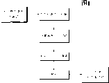
本发明的典型要素、操作特征、应用和/或优点包含于结构和操作的详细内容中,如以后的内容中更全面的描写、描述和要求的:附图的参考文献形成它的一部分,其中相同的数字始终指相同的部分。其它要素、操作特征、应用和/或优点对技术人员来说根据在详细描述中叙述的确定的示范性实施方式来说是显而易见的。其中,图1举例说明了根据本发明的一个示范性实施方式的典型工艺方法。The typical elements, operating features, applications and/or advantages of the present invention are included in the details of construction and operation, as more fully described, described and claimed in the following content: references to the accompanying drawings form a part thereof, wherein Like numbers refer to like parts throughout. Other elements, operational features, applications and/or advantages will be apparent to the skilled person from certain exemplary embodiments recited in the detailed description. Wherein, FIG. 1 illustrates a typical process method according to an exemplary embodiment of the present invention.
具体实施方式Detailed ways
下列描述是本发明的示范性实施方式和发明人构思的最佳模式,但并不意在以任何方式限制本发明的范围、应用和结构。更确切地,下列描述意在提供实现本发明各种实施方式的合适的实例。显然,在不背离本发明实质和范围的情况下,公开的示范性实施方式可以在功能和/或任何要素的配置上作出改变。The following descriptions are exemplary embodiments of the present invention and the best mode conceived by the inventors, but are not intended to limit the scope, application and structure of the present invention in any way. Rather, the following description is intended to provide suitable examples for implementing various embodiments of the invention. It will be apparent that changes may be made in the function and/or arrangement of any element of the disclosed exemplary embodiments without departing from the spirit and scope of the invention.
如此处所用,术语“清洁”、“分离”、“分隔”、“纯化”和它们的任何变化,一般可以交换使用,可以理解为一般包括控制或其它改变第一化学物质关于第二化学物质的空间和/或时间的分配函数。而且,术语“清洁”、“分离”、“分隔”和“纯化”或者任何变化或它们的组合,一般意在包括被认作至少易于描述为、或一般是指至少一种化合物从一个区域到另一个区域的运动的任何事,以便:(1)相对减少一个区域或其周围的浓度,和/或(2)相对增加另一个区域或其周围的浓度。在术语“清洁”和/或“纯化”的情况下,此工艺一般可以理解为包括在被“清洁”和/或“纯化”物质中或其周围的污染混合物浓度的降低。另外,如此处所用,术语“碳纳米结构”、“碳纳米物质”、“纳米形态碳”和它们的任何变化,一般可以理解为包括:例如碳纳米管、碳纳米纤维、碳纳米多面体和这些现在已知或来自下文或现有技术中其它描述的碳的其它纳米态形式中的至少一种。如此处所用,术语“色谱法”和“色谱分离”和任何上下文指示物和它的变化,一般意在包括适用于分离的任何方法、技术、工艺、装置、设备或系统或者至少一种包括至少一种分析物的试样以便生产或另外控制任何成分分析物的空间和/或时间分配和/或在所述试样中分析物成分的组合的其它工艺。另外,如此处所用,术语“光谱”、“显微镜方法”和它们的任何变化,一般意在包括适用于读取或其它处理分析物—参考物数据的任何方法、技术、工艺、装置、设备和/或系统,以便确定任何一种分析物和/或任何分析物组合的存在和/或不存在和/或浓度。As used herein, the terms "clean," "isolate," "separate," "purify," and any variations thereof, are generally used interchangeably, and are understood to generally include controlling or otherwise altering the relationship of a first chemical species with respect to a second chemical species. Allocation functions for space and/or time. Moreover, the terms "clean", "isolate", "separate" and "purify", or any variation or combination thereof, are generally intended to include those considered to at least readily describe, or generally refer to, at least one compound from a region to Anything that moves another area so as to: (1) relatively decrease the concentration in or around one area, and/or (2) relatively increase the concentration in or around another area. In the context of the terms "cleaning" and/or "purifying", the process is generally understood to include the reduction of the concentration of contaminating compounds in or around the material being "cleaned" and/or "purified". In addition, as used herein, the terms "carbon nanostructure", "carbon nanomaterial", "nanomorphic carbon" and any variations thereof are generally understood to include: for example, carbon nanotubes, carbon nanofibers, carbon nanopolyhedra and these At least one of the other nanostate forms of carbon now known or derived from below or otherwise described in the prior art. As used herein, the terms "chromatography" and "chromatographic separation" and any contextual designators, and variations thereof, are generally intended to include any method, technique, process, device, apparatus, or system suitable for separation or at least one method comprising at least A sample of an analyte for the purpose of producing or otherwise controlling the spatial and/or temporal distribution of any constituent analytes and/or other processes for the combination of analyte constituents in said sample. Additionally, as used herein, the terms "spectroscopy," "microscopy," and any variations thereof are generally intended to include any method, technique, process, device, apparatus, and method suitable for reading or otherwise processing analyte-reference data. and/or a system to determine the presence and/or absence and/or concentration of any one analyte and/or any combination of analytes.
示范性应用的详述,即用于CNT的非氧化性清洁方法,根据本发明的各种实施方式,作为能被技术人员推广为纳米态碳纯化和/或分离的任何应用的特殊授权公开内容提供。而且,技术人员可以理解本发明的原理能被用来确定和/或实现许多与纳米形态碳纯化有关的其它益处,例如(但不限于):生产率的提高、合成成本的降低、改善的工艺控制和现在已知或在下文中现有技术中描述的任何其它应用和/或益处。DETAILED DESCRIPTION OF EXEMPLARY APPLICATIONS, ie non-oxidative cleaning methods for CNTs, according to various embodiments of the present invention, as specifically authorized disclosure for any application that can be generalized by the skilled artisan to nanostate carbon purification and/or separation supply. Moreover, the skilled artisan will appreciate that the principles of the present invention can be used to identify and/or realize many other benefits associated with nanomorphic carbon purification, such as (but not limited to): increased productivity, reduced synthesis cost, improved process control and any other applications and/or benefits now known or described in the prior art hereinafter.
色谱法Chromatography
一般而言,化学分析技术的大部分是最优选的,很少数(如果有)是实际专用的。因此,分析物从不同种类的多成分试样中的分离在许多分析步骤中常常是重要的步骤。实施分析分离的最广泛使用的常规方法是电泳和色谱法:两者都包括在几乎所有科学学科中找到应用的方法。In general, the majority of chemical analysis techniques are the most preferred, and few, if any, are actually specific. Therefore, the separation of analytes from different kinds of multi-component samples is often an important step in many analytical procedures. The most widely used routine methods for performing analytical separations are electrophoresis and chromatography: both include methods that find applications in almost all scientific disciplines.
柱色谱法是20世纪之交不久由苏联植物学家Mikhail Tswett发明并命名的。Tswett采用该技术将试样溶液通过填充了磨碎碳化钙的玻璃柱状物来分离各种植物色素(即,叶绿素和叶黄素)。分离后的溶质看起来象柱状物上的色带。因而,Tswett从希腊语中表示“颜色”的chroma和表示“书写”的graphein来给该技术命名。Column chromatography was invented and named by Soviet botanist Mikhail Tswett shortly after the turn of the 20th century. Tswett employed this technique to separate the various plant pigments (ie, chlorophyll and xanthophyll) by passing a sample solution through a glass column filled with ground calcium carbide. The separated solutes appear as colored bands on the column. Thus, Tswett named the technique from the Greek chroma for "color" and graphein for "writing."
由于一些新型方法的发展,以及工程师和科学家们对更好表征复杂混合物方法的进一步需求,在过去的五十年里,出现了各种色谱技术。这些技术的重要影响可由对Martin和Synge在色谱法领域的发现而授予1952诺贝尔奖来证实。也许更瞩目的是1937年和1972年期间基于依赖各种色谱法技术相关工作的12项诺贝尔奖。Various chromatographic techniques have emerged over the past fifty years due to the development of several novel methods and the further demand from engineers and scientists for methods to better characterize complex mixtures. The important impact of these techniques is evidenced by the award of the 1952 Nobel Prize to Martin and Synge for their discoveries in the field of chromatography. Perhaps more notable were the 12 Nobel Prizes awarded between 1937 and 1972 based on related work relying on various chromatography techniques.
一般而言,色谱法包括一组不同而重要的方法,它们允许复杂混合物分析物成分的分离,其中这些分离中的许多通过其它方法也许不可能或者很难实现。典型地,试样在流动相(它可以是气体、液体或超临界流体)中溶解。然后使流动相通过不混溶固定相,它通常固定于柱状物或固体表面。可选择两相以便试样成分在流动相和固定相之间将它们分配至可变的程度。这些被固定相强烈阻滞的分析物成分一般随流动相的流动缓慢移动。相反地,那些被固定相微弱控制的分析物成分一般移动较快。由于流速(例如,流动性)的不同,分析物成分典型地分离至一般可以进行定性和/或定量分析的不连续带中。参见例如:E.Heftmann,Chromatography:Fundamentals and Applications ofChromatography and Electrophotometric Methods,1983;P.Sewell和B.Clarke,Chromatographic Separations,1988;J.A.Jonsson,Chromatographic Theory and Basic Principles,1987;R.M.Smith,Gasand Liquid Chromatography in Analytical Chemistry,1988;E.Katz,Quantitative Analysis Using Chromatographic Techniques,1987;和J.C.Giddings,Unified Separation Science,1991。一般而言,根据色谱领域溶质分析物和固定相之间的作用机理,色谱法典型地被分成五个大类:吸附色谱法、分配色谱法、离子交换色谱法、分子排阻色谱法和亲合色谱法。In general, chromatography encompasses a diverse and important set of methods that allow the separation of analyte components of complex mixtures, many of which may be impossible or difficult to achieve by other methods. Typically, the sample is dissolved in a mobile phase (which can be a gas, liquid or supercritical fluid). The mobile phase is then passed through an immiscible stationary phase, which is usually immobilized on a column or solid surface. The two phases can be chosen so that the sample components partition them to a variable degree between the mobile and stationary phases. These analyte components, which are strongly retarded by the stationary phase, generally move slowly with the flow of the mobile phase. Conversely, those analyte components that are weakly controlled by the stationary phase generally move faster. Due to differences in flow rate (eg, mobility), analyte components are typically separated into discrete bands that generally allow qualitative and/or quantitative analysis.参见例如:E.Heftmann,Chromatography:Fundamentals and Applications ofChromatography and Electrophotometric Methods,1983;P.Sewell和B.Clarke,Chromatographic Separations,1988;J.A.Jonsson,Chromatographic Theory and Basic Principles,1987;R.M.Smith,Gasand Liquid Chromatography in Analytical Chemistry, 1988; E. Katz, Quantitative Analysis Using Chromatographic Techniques, 1987; and J.C. Giddings, Unified Separation Science, 1991. In general, chromatography is typically divided into five broad categories based on the mechanism of interaction between a solute analyte and a stationary phase in the field of chromatography: adsorption chromatography, partition chromatography, ion exchange chromatography, size exclusion chromatography, and affinity chromatography. chromatography.
吸附色谱法一般被认为是色谱法的最古老形式,它采用固体固定相和液体或气体流动相。溶质通常被吸附到固定相颗粒的表面,同时固定相和流动相之间的平衡导致溶质分析物的分离。Adsorption chromatography, generally considered the oldest form of chromatography, employs a solid stationary phase and a liquid or gaseous mobile phase. Solutes are typically adsorbed to the surface of stationary phase particles, while equilibrium between stationary and mobile phases results in the separation of solute analytes.
分配色谱法涉及在固定支撑物表面的薄膜上形成液体固定相。溶质在固定液体和流动相之间平衡。在吸附和分配色谱法中,在流动和固定相之间发生了溶质的基本连续平衡。柱状物可以填充固定相或可以是内壁包覆固定相的敝口管。Partition chromatography involves the formation of a liquid stationary phase on a thin film on the surface of an immobilized support. The solute is in equilibrium between the stationary liquid and the mobile phase. In adsorption and partition chromatography, an essentially continuous equilibrium of solutes occurs between the mobile and stationary phases. Columns can be filled with stationary phase or can be open tubes with stationary phase coated inside.
离子交换色谱法采用共价地附着于固体固定相(即,通常是树脂)的阴离子(即,SO3 -)或阳离子(即,N(CH3)3 +),且流动相典型地是液体。相反电荷的分析物溶质离子通过库仑力附着于固定相。Ion exchange chromatography employs anions (ie, SO 3 − ) or cations (ie, N(CH 3 ) 3 + ) covalently attached to a solid stationary phase (ie, usually a resin), and the mobile phase is typically a liquid . The oppositely charged analyte solute ions are attached to the stationary phase by Coulombic forces.
分子排阻色谱法(例如,凝胶过滤或凝胶渗透色谱法)依据尺寸分离分子,较大的分析物溶质通过色谱场比较小的更快。与其它形式的色谱法不同,在固定相和分析物溶质之间一般没有吸引的作用,而是,液体或气体流动相通过多孔凝胶。这些孔一般足够小以便将较大的分子而不是小分子排除在外,因为较小的分子进入了凝胶孔,通常会花费较长的时间通过柱状物,因此在离开柱状物之前必须流过较大体积。在分子排阻色谱法中,溶质可利用的固定相体积比例一般会随溶质分子尺寸的增加而减少。Size exclusion chromatography (eg, gel filtration or gel permeation chromatography) separates molecules based on size, with larger analyte solutes passing through the chromatographic field faster than smaller ones. Unlike other forms of chromatography, there is generally no attractive interaction between the stationary phase and the analyte solute; instead, the liquid or gaseous mobile phase passes through the porous gel. These pores are generally small enough to exclude larger molecules rather than small molecules, since smaller molecules enter the gel pores and usually take longer to pass through the column and therefore have to flow through a longer column before leaving the column. large volume. In size exclusion chromatography, the fraction of stationary phase volume available to a solute generally decreases as the molecular size of the solute increases.
亲合色谱法一般被认为是色谱法的最优选类型:采用共价地附着于(例如,固定不动地)固定相的一种和第二种分析物分子之间特定的相互作用。亲合色谱法一般依赖于固定相和不同种类试样中至少一种分析物溶质之间的化学特定的、非共价的相互作用。Affinity chromatography is generally considered the most preferred type of chromatography: employing specific interactions between one and a second analyte molecule covalently attached (eg, immobilized) to a stationary phase. Affinity chromatography generally relies on chemically specific, non-covalent interactions between a stationary phase and at least one analyte solute in a sample of a different type.
流动相通过色谱场的速度可以以体积流速或线性流速表示。例如,考虑液体色谱法试验,其中柱状物具有0.60cm的内径(半径r=0.30cm),且流动相占有柱状物体积的20%。柱状物长度l每厘米具有的体积相当于πr2l;此处为0.283mL,流动相(例如,溶剂系统)占20%(例如,0.0565mL)。体积流速(即,


从色谱场洗脱(elute)的分析物可以用各种检测器观察到,比如:热导检测器、火焰电离检测器、电子俘获检测器、火焰光度检测器、碱焰检测器、硫化学发光检测器、原子发射检测器等。作为洗脱时间的函数响应的检测器踪迹(trace)被认为是色谱。每一成分的滞留时间tr是试样喷射到色谱场后直到相应分析物被探测到所需要的时间。未滞留的流动相以最小时间tm通过柱状物。溶质的修正滞留时间tr′是分析物通过色谱场线性传输距离需要的额外时间,超过未滞留溶剂需要的时间,等于tr′=tr-tm。Analytes eluting from the chromatographic field can be observed with various detectors, such as: thermal conductivity detector, flame ionization detector, electron capture detector, flame photometric detector, alkaline flame detector, sulfur chemiluminescence detectors, atomic emission detectors, etc. The trace of the detector responding as a function of elution time is considered a chromatogram. The retention time tr of each component is the time required for the corresponding analyte to be detected after the sample is injected into the chromatographic field. Unretained mobile phase passes through the column with a minimum time tm . The corrected retention time t r ' of a solute is the additional time required for the analyte to travel the distance linearly through the chromatographic field, beyond the time required for the unretained solvent, equal to t r ' = t r -t m .
两种成分的相对滞留时间以相应修正滞留时间的商给出。单个成分的容量因子是修正滞留时间除以溶剂洗脱时间。容量因子一般是指溶质在固定相中花费的时间与在流动相中花费时间的比。当从小试样负载按比例增加到大负载时,柱状物的横截面积典型地与试样负载成比例增加。而柱状物长度和线性流速一般保持恒定。The relative residence times of the two components are given as the quotient of the corresponding corrected residence times. The capacity factor for an individual component is the corrected retention time divided by the solvent elution time. Capacity factor generally refers to the ratio of the time a solute spends in the stationary phase to the time it spends in the mobile phase. When scaling from small to large specimen loads, the cross-sectional area of the pillars typically increases in proportion to the specimen load. Whereas column length and linear flow rate are generally kept constant.
对于任何两种成分1和2,相对滞留值α定义为

给出无限渗透性的色谱场,截面面积A从x延伸到x+l(其中l表示流程线性传输距离),色谱场的体积可以表示为V=Al。使分析物溶质成分G在时间t时点x的浓度为[G]。相应地,单位时间内进入色谱场的颗粒数量是JA,其中J是溶质颗粒流量。因此,在色谱场内,由入射粒子流量引起的摩尔浓度的增长率是
假设:(1)在色谱场内扩散的溶质颗粒流量J包括与由浓度梯度而来的热力学力F相应的运动;(2)当热力学力F与粘滞曳力匹配时,溶质颗粒达到稳定态漂移速率s;(3)漂移速率s与热力学力F成比例;(4)溶质颗粒流罱J与漂移速率成比例;和(5)热力学力F与空间浓度梯度
或比例。最终的比例链是J∝S,S∝F和


其次,考虑洗脱成分G的局部分子压力p与给定体积V的色谱场的时间相关性。“理想气体定律”pV=nRT,它适用分子级系统,对于大颗粒聚合物(即,分子的克分子量),则变为pV=nKT,其中:p是局部分子压力;V是假设局部边界条件下的容器体积;n是颗粒个数;k是玻耳兹曼常数;T是温度。求解局部压力得到
对于当溶质流失时,不随时间补充的洗脱的分析物溶质,溶质颗粒数量的时间变化率以
在恒定温度,对于局部压力
因此,将前述导出的与菲克扩散第二定律相应的浓度速度表达式代入,在作为溶质颗粒浓度[G]函数的无限渗透力色谱场的三维空间扩散的溶质颗粒的压力速度的一般表达式可以表示为Therefore, substituting the previously derived concentration velocity expression corresponding to Fick's second law of diffusion into the general expression of the pressure velocity of the solute particle diffused in the three-dimensional space of the infinite osmotic force chromatographic field as a function of the concentration [G] of the solute particle It can be expressed as
然而,如果假定色谱场具有有限的扩散渗透力(实际上,正如实现色谱分离一般所需的),可能会包括其它的扩散系数 以说明不同的渗透力度量标准,比如,色谱理论平台的数量、色谱平台高度、固定相吸附、非均匀孔隙度、沿不同空间的各向异性传输、疏水性、毛细缺陷等。However, if the chromatographic field is assumed to have limited diffusional penetration (in practice, as generally required to achieve chromatographic separations), other diffusion coefficients may be includedTo account for different permeability metrics, such as the number of chromatographic theoretical platforms, chromatographic platform height, stationary phase adsorption, heterogeneous porosity, anisotropic transport along different spaces, hydrophobicity, capillary defects, etc.
例如,扩散通过色谱场(或者多孔栅栏)Ξ的碳纳米管成分B的表达式:
修正后,此表达式将色谱场内(或多孔栅栏)Ξ任意点的CNT成分B的浓度与此点CNT成分B的浓度的三维变量联系了起来,这就是说B被迫扩散通过色谱场以其浓度梯度从含B浓度较高的体积单元转移到含B浓度较低的体积单元。After correction, this expression links the concentration of CNT component B at any point in the chromatographic field (or porous barrier) to the three-dimensional variable of the concentration of CNT component B at this point, which means that B is forced to diffuse through the chromatographic field to Its concentration gradient shifts from volume cells containing higher B concentrations to volume cells containing lower B concentrations.
在扩散等式
平台高度

溶质分散带的标准偏差一般相应为
其中,H是平台高度,ux是沿色谱场线性传输路线的线性流速,A、B、C是常数:A代表不规则流程,B代表纵向扩散,C代表给定体积下移动和固定相之间分析物溶质传输的有限率。最优流速,它一般最小化平台高度,对气体色谱快于液体色谱。平台数量和最佳流速通常随固定相颗粒的减小而增加。开口管状柱状物比填充的柱状物典型地提供更高的分解度和更短的分析时间。一般而言,带不仅在色谱场而且在试样喷射期间以及成分分析物探测期间扩展。超负载和尾料可以通过用更小的试样或通过掩膜(masking)固定相的强吸附点来修正。另外,有几种基本工艺影响平台高度,比如:纵向扩散、在流动相和/或固定相中的质量传输阻力、涡流扩散。Among them, H is the height of the platform, u x is the linear flow velocity along the linear transmission route of the chromatographic field, A, B, and C are constants: A represents irregular flow, B represents longitudinal diffusion, and C represents the difference between the mobile and stationary phases at a given volume. limited rate of solute transport between analytes. Optimal flow rates, which generally minimize platform height, are faster for gas chromatography than liquid chromatography. The number of platforms and optimum flow rate generally increase with smaller stationary phase particles. Open tubular columns typically provide higher resolution and shorter analysis times than packed columns. In general, bands expand not only in the chromatographic field but also during sample injection and component analyte detection. Overloading and tailing can be corrected by using smaller samples or by masking strong adsorption sites of the stationary phase. Additionally, there are several fundamental processes that affect platform height, such as: longitudinal diffusion, mass transport resistance in the mobile and/or stationary phase, and eddy diffusion.
为了监控特定柱状物的性能,通常推荐试验来定期测定标准试样的容量因子、理论平台数量和/或峰值不对称性。任何这些数值的变化一般表明色谱场随时间和/或重复使用而退化。To monitor the performance of a particular column, tests are often recommended to periodically determine the capacity factor, number of theoretical plateaus, and/or peak asymmetry of standard samples. Changes in any of these values generally indicate degradation of the chromatographic field over time and/or repeated use.
碳纳米管的非氧化性清洁Non-oxidative cleaning of carbon nanotubes
现有技术已知各种生产碳纳米管(CNT)的方法,比如:激光消融(laser ablation)、碳弧沉积、化学气相沉积(CVD)等。这些技术典型地导致不同量的污染物,比如:无定形碳和原反应产品中的晶体。常规方法一般涉及将反应产品混合物暴露于强氧化剂中以有效地连续除去无定形碳,接着通过酸洗除去金属结晶体。这些步骤一般不能除去原产品材料中存在的所有污染物,而且事实上,可能会引起损坏,比如CNT的外壁。Various methods for producing carbon nanotubes (CNTs) are known in the prior art, such as laser ablation, carbon arc deposition, chemical vapor deposition (CVD) and the like. These techniques typically result in varying amounts of contaminants such as: amorphous carbon and crystals in the original reaction products. Conventional methods generally involve exposing the reaction product mixture to a strong oxidizing agent to effectively remove the amorphous carbon continuously, followed by acid washing to remove the metal crystals. These steps generally do not remove all contaminants present in the original product material and, in fact, may cause damage, such as the outer walls of the CNTs.
在代表性方面,根据本发明的一个示范性实施方式,例如在图1中所述,一种基本非化学反应性方法,其描述了在纳米态碳试样中存在的残余催化剂和无定形碳可以被有效分隔。一种CNT清洁的示范性工艺,例如,包括:提供未处理的纳米态CNT试样(步骤110);在有机溶剂(即丙酮或甲酰胺)中溶解CNT试样(步骤110);选择性超声波处理溶剂化处理的产品混合物;在约20,000 RCF(例如,相对离心力;也叫作“重力”)离心分离试样约30分钟(步骤120);轻轻倒掉上层清液(步骤130)。观察到污染物质一般保持悬浮,而CNT沉积到离心管的底部。可以重复该步骤直到上层清液在离心作用(典型地,3至4次)后几乎无色。作为选择,结合地或连续地,将上层清液光谱分析以更精确地确定污染物和/或无定形碳物质的相对浓度以便确定重复纯化步骤的终点。纯化步骤例如可以通过分析显微镜方法和扫描电子显微镜方法实现。所述分析光谱包括紫外光谱、红外光谱、核磁共振光谱、拉曼光谱、荧光光谱和质谱分析中的至少一种。这样来自仍与纳米形态碳接触的溶剂的残余污染物就被除去了。例如,用醇洗(步骤140)以分离至少部分纯化的CNT(步骤150)。已经观察到公开的清洁步骤,正如通过透射电子显微镜和红外光谱仪证实的一样非常有效。其它各种光谱仪和/或显微镜也可被选择地、结合地或连续地用来确定或表征污染物和纳米态碳物质相对后分离(post-separation)的浓度比。In a representative aspect, according to an exemplary embodiment of the present invention, such as depicted in FIG. can be effectively separated. An exemplary process for CNT cleaning, for example, includes: providing an untreated nano-state CNT sample (step 110); dissolving the CNT sample in an organic solvent (i.e., acetone or formamide) (step 110); selectively sonicating The solvated product mixture is processed; the sample is centrifuged at about 20,000 RCF (eg, relative centrifugal force; also referred to as "gravity") for about 30 minutes (step 120); the supernatant is decanted (step 130). It was observed that the contaminating species generally remained in suspension, while the CNTs settled to the bottom of the centrifuge tube. This step can be repeated until the supernatant is almost colorless after centrifugation (typically, 3 to 4 times). Alternatively, combined or sequentially, the supernatant is spectroscopically analyzed to more precisely determine the relative concentrations of contaminants and/or amorphous carbon species to determine the endpoint of repeated purification steps. Purification steps can be achieved, for example, by analytical microscopy and scanning electron microscopy. The analysis spectrum includes at least one of ultraviolet spectrum, infrared spectrum, nuclear magnetic resonance spectrum, Raman spectrum, fluorescence spectrum and mass spectrometry. In this way residual contamination from the solvent still in contact with the nanomorphic carbon is removed. For example, washing with alcohol (step 140) to isolate at least partially purified CNTs (step 150). The disclosed cleaning procedure has been observed to be very effective as demonstrated by transmission electron microscopy and infrared spectroscopy. Various other spectrometers and/or microscopes may also be used alternatively, in combination or continuously to determine or characterize the relative post-separation concentration ratios of pollutants and nanocarbon species.
各种有机溶剂,比如极性疏质子和极性质子溶剂,可选择地、结合地或连续地被使用,且可以包括二甲基亚砜(CH3SOCH3)、二甲基甲酰胺(HCON(CH3)2)、甲酰胺(HCONH2)、n-己烷(CH3(CH2)4CH3)、丙酮(CH3COCH3)和其它现在已知或来自下文或现有技术描述的任何有机溶剂和/或溶剂系统中的至少一种。醇洗也可以选择地、结合地或连续地包括甲醇(CH3OH)、乙醇(CH3CH2OH)、n-丙醇(CH3(CH2)2OH)、异丙醇((CH3)2CHOH)、n-丁醇(CH3(CH2)3OH)、异丁醇((CH3)3COH)和任何其它醇(R-OH)和/或现在已知的或来自下文或现有技术描述的基本可混醇溶剂系统中的至少一种。另外,所得的至少部分纯化的纳米态碳试样可以随后通过任何此处描述的、现在已知的或下文来自现有技术的色谱方法进一步分离。Various organic solvents, such as polar aprotic and polar protic solvents, are used alternatively, in combination or in succession, and may include dimethyl sulfoxide (CH 3 SOCH 3 ), dimethylformamide (HCON (CH 3 ) 2 ), formamide (HCONH 2 ), n-hexane (CH 3 (CH 2 ) 4 CH 3 ), acetone (CH 3 COCH 3 ) and others now known or from below or described in the prior art at least one of any organic solvent and/or solvent system. Alcohol washes may also optionally, in combination or sequentially include methanol (CH 3 OH), ethanol (CH 3 CH 2 OH), n-propanol (CH 3 (CH 2 ) 2 OH), isopropanol ((CH 3 ) 2 CHOH), n-butanol (CH 3 (CH 2 ) 3 OH), isobutanol ((CH 3 ) 3 COH) and any other alcohol (R-OH) and/or now known or derived from At least one of the substantially miscible alcohol solvent systems described below or in the prior art. In addition, the resulting at least partially purified nano-carbon sample can then be further separated by any of the chromatographic methods described herein, now known or hereinafter from the prior art.
在前面的详述中,本发明已经参考特殊的示范性实施方式作了例证,但是,可以理解,在不背离如下面权利要求阐述的本发明范围的情况下,可以进行各种改变和变化。详述可以认为是以典型方式,而不是限制方式,且所有这些改变都应该包括在本发明的范围内。因此,本发明的范围应该由此处所附的权利要求和它们的等同物而不仅仅是上述的实施例来确定。例如,在任何方法或工艺权利要求中的陈述的步骤可以以任何顺序实施以产生与本发明基本相同的结果,因此不限于权利要求中陈述的特殊结构。In the foregoing detailed description, the invention has been illustrated with reference to specific exemplary embodiments, however, it will be understood that various changes and changes may be made without departing from the scope of the invention as set forth in the following claims. The detailed description is to be considered in a typical manner, rather than a limiting one, and all such modifications are intended to be within the scope of the invention. Accordingly, the scope of the present invention should be determined by the claims appended hereto and their equivalents rather than by the above-described embodiments only. For example, the steps recited in any method or process claims can be performed in any order to produce substantially the same result of the invention and, therefore, are not limited to the specific structure recited in the claims.
关于特殊实施方式,已经在上面描述了益处、其它优点和问题的解决办法。但是,任何益处、优点和问题的解决办法或任何可能引起任何特殊利益、优点或解决办法发生或变得更明显的要素不应该被解释为任何或所有权利要求的主要的、需要的或必要的特征或成分。正如此处所用的术语“包括”、“包含”或它们的任何变化,旨在提及一种非限制性包含,这样,包括一系列要素的工艺、方法、制品、组分或装置不仅仅含有这些所述要素,而且可以含有未清楚地列出或这些工艺、方法、制品、组分或装置固有的其它要素。上述结构、排列、应用、比例、要素、材料或本发明实际使用的成分的其它组合和/或改变,在不背离上述一般原理的情况下,除那些没有特别描述的之外、本领域技术人员可以改变或特别应用于特殊的环境、生产规范、设计参数或其它操作要求。Benefits, other advantages, and solutions to problems have been described above with respect to particular embodiments. However, no benefit, advantage or solution to a problem or any element which may cause any particular benefit, advantage or solution to occur or become more apparent should not be construed as essential, required or essential to any or all claims characteristics or ingredients. As used herein, the terms "comprises," "comprising," or any variation thereof, are intended to refer to a non-limiting inclusion such that a process, method, article, component or device comprising a series of elements does not merely contain These recited elements, in addition, may contain other elements not expressly listed or inherent in the process, method, article, component or apparatus. Other combinations and/or changes of the above structures, arrangements, applications, ratios, elements, materials or components used in the practice of the present invention, without departing from the above general principles, except those not specifically described, are within the reach of those skilled in the art Can be changed or specially adapted to special circumstances, production specifications, design parameters or other operational requirements.
Claims (16)
Applications Claiming Priority (2)
| Application Number | Priority Date | Filing Date | Title |
|---|---|---|---|
| US10/174,299 | 2002-06-18 | ||
| US10/174,299 US7029645B2 (en) | 2002-06-18 | 2002-06-18 | Method for non-reactive separation of nanomorphic carbon species |
Publications (2)
| Publication Number | Publication Date |
|---|---|
| CN1662445A CN1662445A (en) | 2005-08-31 |
| CN1325373C true CN1325373C (en) | 2007-07-11 |
Family
ID=29733544
Family Applications (1)
| Application Number | Title | Priority Date | Filing Date |
|---|---|---|---|
| CNB038139936A Expired - Fee Related CN1325373C (en) | 2002-06-18 | 2003-06-04 | Non-destructive separation of nanomorphic carbon species |
Country Status (7)
| Country | Link |
|---|---|
| US (1) | US7029645B2 (en) |
| EP (1) | EP1511685A1 (en) |
| JP (1) | JP2005529826A (en) |
| KR (1) | KR100672226B1 (en) |
| CN (1) | CN1325373C (en) |
| AU (1) | AU2003240526A1 (en) |
| WO (1) | WO2003106337A1 (en) |
Families Citing this family (15)
| Publication number | Priority date | Publication date | Assignee | Title |
|---|---|---|---|---|
| US7135160B2 (en) * | 2002-04-02 | 2006-11-14 | Carbon Nanotechnologies, Inc. | Spheroidal aggregates comprising single-wall carbon nanotubes and method for making the same |
| US7124764B2 (en) * | 2004-12-29 | 2006-10-24 | Industrial Technology Research Institute | Method for removing impurities from porous materials |
| KR100674404B1 (en) * | 2005-07-05 | 2007-01-29 | 재단법인서울대학교산학협력재단 | Carbon nanotube coated heat sink and its manufacturing method |
| FR2892563B1 (en) * | 2005-10-25 | 2008-06-27 | Commissariat Energie Atomique | POLYMERIC NANOFIBRIDE NETWORK FOR PHOTOVOLTAIC CELLS |
| KR100791036B1 (en) * | 2006-07-07 | 2008-01-03 | 한국과학기술원 | Separation method of pure carbon nanotubes and carbon nanotubes containing metal impurities using continuous magnetophoresis and magnetophoretic microfluidic control device |
| KR100790839B1 (en) * | 2006-07-31 | 2008-01-02 | 세종대학교산학협력단 | Nondestructive Purification of Carbon Nanotubes |
| EP1894906A1 (en) | 2006-08-28 | 2008-03-05 | Bruker BioSpin AG | Superconducting element containing MgB2 |
| CN100435965C (en) * | 2006-11-28 | 2008-11-26 | 厦门大学 | Method for separating micro Nano material |
| US20080290007A1 (en) * | 2007-05-24 | 2008-11-27 | National Institute Of Standards And Technology | Centrifugal length separation of carbon nanotubes |
| US8101709B1 (en) * | 2007-05-31 | 2012-01-24 | The Regents Of The University Of California | Synthesis of conducting polymer nanofibers using an oligomer of a monomer as an initiator |
| KR101501599B1 (en) * | 2008-10-27 | 2015-03-11 | 삼성전자주식회사 | METHOD OF REMOVING CARBONIZING CATALYST FROM GRAPHENE SHEET AND METHOD FOR TRANSFERRING GRAPHENE SHEET |
| US8365923B2 (en) * | 2008-10-31 | 2013-02-05 | The University Of Western Australia | Methods for selectively separating carbon nanotubes |
| US9156698B2 (en) | 2012-02-29 | 2015-10-13 | Yazaki Corporation | Method of purifying carbon nanotubes and applications thereof |
| CN106040589B (en) * | 2016-07-11 | 2018-08-31 | 阜阳师范学院 | A method of separation different-grain diameter nanometer aluminium powder |
| KR102420365B1 (en) * | 2020-04-07 | 2022-07-14 | 주식회사 한솔케미칼 | System for massive purificating nanoparticles and massive purification method using the same |
Citations (3)
| Publication number | Priority date | Publication date | Assignee | Title |
|---|---|---|---|---|
| US5560898A (en) * | 1993-08-04 | 1996-10-01 | Director-General Of Agency Of Industrial Science And Technology | Process of isolating carbon nanotubes from a mixture containing carbon nanotubes and graphite particles |
| JPH10120409A (en) * | 1996-10-17 | 1998-05-12 | Toyo Tanso Kk | Separation and purification of monolayered nanotube and separation ad purification of metal-including nanocapsule |
| CN1277146A (en) * | 1999-06-15 | 2000-12-20 | 李铁真 | Method for purifying carbon nanometre tube in large scale |
Family Cites Families (2)
| Publication number | Priority date | Publication date | Assignee | Title |
|---|---|---|---|---|
| JPH06183712A (en) | 1992-10-23 | 1994-07-05 | Showa Denko Kk | Production of fullerenes |
| US6576341B1 (en) | 1998-04-09 | 2003-06-10 | Horcom Limited | Composition |
-
2002
- 2002-06-18 US US10/174,299 patent/US7029645B2/en not_active Expired - Fee Related
-
2003
- 2003-06-04 AU AU2003240526A patent/AU2003240526A1/en not_active Abandoned
- 2003-06-04 CN CNB038139936A patent/CN1325373C/en not_active Expired - Fee Related
- 2003-06-04 KR KR1020047020614A patent/KR100672226B1/en not_active Expired - Fee Related
- 2003-06-04 WO PCT/US2003/017557 patent/WO2003106337A1/en not_active Ceased
- 2003-06-04 EP EP03731537A patent/EP1511685A1/en not_active Withdrawn
- 2003-06-04 JP JP2004513174A patent/JP2005529826A/en not_active Withdrawn
Patent Citations (3)
| Publication number | Priority date | Publication date | Assignee | Title |
|---|---|---|---|---|
| US5560898A (en) * | 1993-08-04 | 1996-10-01 | Director-General Of Agency Of Industrial Science And Technology | Process of isolating carbon nanotubes from a mixture containing carbon nanotubes and graphite particles |
| JPH10120409A (en) * | 1996-10-17 | 1998-05-12 | Toyo Tanso Kk | Separation and purification of monolayered nanotube and separation ad purification of metal-including nanocapsule |
| CN1277146A (en) * | 1999-06-15 | 2000-12-20 | 李铁真 | Method for purifying carbon nanometre tube in large scale |
Non-Patent Citations (1)
| Title |
|---|
| 碳纳米管纯化技术研究 杨占红、李新海、李晶、王红强、方惠会、陈志国,中南工业大学学报(自然科学版),第30卷第4期 1999 * |
Also Published As
| Publication number | Publication date |
|---|---|
| EP1511685A1 (en) | 2005-03-09 |
| AU2003240526A1 (en) | 2003-12-31 |
| WO2003106337A1 (en) | 2003-12-24 |
| CN1662445A (en) | 2005-08-31 |
| KR100672226B1 (en) | 2007-01-24 |
| JP2005529826A (en) | 2005-10-06 |
| KR20050023315A (en) | 2005-03-09 |
| US20030232002A1 (en) | 2003-12-18 |
| US7029645B2 (en) | 2006-04-18 |
Similar Documents
| Publication | Publication Date | Title |
|---|---|---|
| CN1325373C (en) | Non-destructive separation of nanomorphic carbon species | |
| Doorn et al. | Capillary electrophoresis separations of bundled and individual carbon nanotubes | |
| Huang et al. | High-resolution length sorting and purification of DNA-wrapped carbon nanotubes by size-exclusion chromatography | |
| Hersam | Progress towards monodisperse single-walled carbon nanotubes | |
| Fagan et al. | Length fractionation of carbon nanotubes using centrifugation | |
| Flavel et al. | Separation of single-walled carbon nanotubes with a gel permeation chromatography system | |
| Valcárcel et al. | Carbon nanostructures as sorbent materials in analytical processes | |
| Liu et al. | Large-scale single-chirality separation of single-wall carbon nanotubes by simple gel chromatography | |
| Dyke et al. | Separation of single-walled carbon nanotubes on silica gel. Materials morphology and Raman excitation wavelength affect data interpretation | |
| KR101425690B1 (en) | Monodisperse single wall carbon nanotube clusters and related methods of providing them | |
| US20090041404A1 (en) | Fiber sensor production | |
| Yu et al. | (n, m) Structural assignments and chirality dependence in single-wall carbon nanotube Raman scattering | |
| US8715607B2 (en) | Method for separating and collecting carbon nanotube, and carbon nanotube | |
| Wei et al. | Selective enrichment of (6, 5) and (8, 3) single-walled carbon nanotubes via cosurfactant extraction from narrow (n, m) distribution samples | |
| Kawai et al. | Single chirality extraction of single-wall carbon nanotubes for the encapsulation of organic molecules | |
| US20080290007A1 (en) | Centrifugal length separation of carbon nanotubes | |
| US20100111814A1 (en) | Chirality-based separation of carbon nanotubes | |
| Fujimori et al. | One step fabrication of aligned carbon nanotubes using gas rectifier | |
| Hu et al. | Spectroscopic insights into the influence of filling carbon nanotubes with atomic nanowires for photophysical and photochemical applications | |
| Abbasian et al. | Solid‐phase microextraction of ultra‐trace amounts of tramadol from human urine by using a carbon nanotube/flower‐shaped zinc oxide hollow fiber | |
| Blum et al. | Selective bundling of zigzag single-walled carbon nanotubes | |
| US7037479B2 (en) | Method for cleaning nanomorphic carbon species | |
| Shapturenka et al. | Universalized and robust length separation of carbon and boron nitride nanotubes with improved polymer depletion-based fractionation | |
| US20060225573A1 (en) | Miniaturized enrichment facility | |
| Taczak | Controlling the structure and properties of carbon nanotubes |
Legal Events
| Date | Code | Title | Description |
|---|---|---|---|
| C06 | Publication | ||
| PB01 | Publication | ||
| C10 | Entry into substantive examination | ||
| SE01 | Entry into force of request for substantive examination | ||
| C14 | Grant of patent or utility model | ||
| GR01 | Patent grant | ||
| C19 | Lapse of patent right due to non-payment of the annual fee | ||
| CF01 | Termination of patent right due to non-payment of annual fee |