CN1324768C - Card connector - Google Patents
Card connector Download PDFInfo
- Publication number
- CN1324768C CN1324768C CNB2004100899127A CN200410089912A CN1324768C CN 1324768 C CN1324768 C CN 1324768C CN B2004100899127 A CNB2004100899127 A CN B2004100899127A CN 200410089912 A CN200410089912 A CN 200410089912A CN 1324768 C CN1324768 C CN 1324768C
- Authority
- CN
- China
- Prior art keywords
- mentioned
- card
- earth terminal
- metal shell
- vertical direction
- Prior art date
- Legal status (The legal status is an assumption and is not a legal conclusion. Google has not performed a legal analysis and makes no representation as to the accuracy of the status listed.)
- Expired - Fee Related
Links
Images

Classifications
-
- H—ELECTRICITY
- H01—ELECTRIC ELEMENTS
- H01R—ELECTRICALLY-CONDUCTIVE CONNECTIONS; STRUCTURAL ASSOCIATIONS OF A PLURALITY OF MUTUALLY-INSULATED ELECTRICAL CONNECTING ELEMENTS; COUPLING DEVICES; CURRENT COLLECTORS
- H01R12/00—Structural associations of a plurality of mutually-insulated electrical connecting elements, specially adapted for printed circuits, e.g. printed circuit boards [PCB], flat or ribbon cables, or like generally planar structures, e.g. terminal strips, terminal blocks; Coupling devices specially adapted for printed circuits, flat or ribbon cables, or like generally planar structures; Terminals specially adapted for contact with, or insertion into, printed circuits, flat or ribbon cables, or like generally planar structures
- H01R12/70—Coupling devices
- H01R12/71—Coupling devices for rigid printing circuits or like structures
-
- H—ELECTRICITY
- H01—ELECTRIC ELEMENTS
- H01R—ELECTRICALLY-CONDUCTIVE CONNECTIONS; STRUCTURAL ASSOCIATIONS OF A PLURALITY OF MUTUALLY-INSULATED ELECTRICAL CONNECTING ELEMENTS; COUPLING DEVICES; CURRENT COLLECTORS
- H01R13/00—Details of coupling devices of the kinds covered by groups H01R12/70 or H01R24/00 - H01R33/00
- H01R13/648—Protective earth or shield arrangements on coupling devices, e.g. anti-static shielding
- H01R13/658—High frequency shielding arrangements, e.g. against EMI [Electro-Magnetic Interference] or EMP [Electro-Magnetic Pulse]
- H01R13/6581—Shield structure
- H01R13/6582—Shield structure with resilient means for engaging mating connector
-
- H—ELECTRICITY
- H01—ELECTRIC ELEMENTS
- H01R—ELECTRICALLY-CONDUCTIVE CONNECTIONS; STRUCTURAL ASSOCIATIONS OF A PLURALITY OF MUTUALLY-INSULATED ELECTRICAL CONNECTING ELEMENTS; COUPLING DEVICES; CURRENT COLLECTORS
- H01R13/00—Details of coupling devices of the kinds covered by groups H01R12/70 or H01R24/00 - H01R33/00
- H01R13/02—Contact members
- H01R13/22—Contacts for co-operating by abutting
- H01R13/24—Contacts for co-operating by abutting resilient; resiliently-mounted
Abstract
The card connector is comprising an insulating housing having a signal terminal and a ground terminal and a metal enclosure for covering the insulating housing. A movable section of the ground terminal is disposed in a vertical upper region of the ground contact section on the card surface inserted in the card containing space. Part of the metal enclosure is positioned at the vertical upper region overlapping the movable section of the ground terminal in a thickness direction of the movable section of the ground terminal so that when the card is inserted into the card containing space, the ground contact section on the card surface contacts with the movable section of the ground terminal, the movable section the ground terminal is moved to a vertical upper section in the direction of thickness, thus increasing a contact pressure between the movable section of the ground terminal and a portion of the metal enclosure by making direct contact therebetween.This invention to provide a card connector having the improved grounding connection.
Description
Technical field
The present invention relates to card connector, particularly relates to the card connector that the metal shell that utilizes card connector is brought into play the ground connection effect.
Background technology
In TOHKEMY 2003-59557 communique, be an example that has disclosed existing card connector for example.This existing card connector has: the metal shell that has disposed the insulation shell of signal terminal and earth terminal and covered the outside of this insulation shell.On this card connector, form: the card receiving space that is used for making the IC-card that disposes signal contact site and grounding parts from the teeth outwards to plug.When the card with IC-card etc. was inserted into the card receiving space, its lip-deep signal contact site and grounding parts contacted with earth terminal with the signal terminal of corresponding insulation shell respectively.
The earth terminal of the insulation shell of this existing card connector, only be actually by the terminal on the substrate that only is provided with for earth terminal with substrate circuit and be connected, so ground connection is insufficient, the result with ground wire, it is very high that the impedance of the grounding parts of IC-card becomes, and be easy to generate noise.
Patent documentation: TOHKEMY 2003-59557 communique
Summary of the invention
The present invention is in order to solve the problem of prior art, purpose is to apply some deformation process by the part at the metal shell of card connector, when card is inserted into card connector, metal shell is used for being connected as ground wire with the grounding parts of card connector, to improve the ground connection effect of card connector.
Card connector of the present invention has: the insulation shell that has disposed signal terminal and earth terminal, and the metal shell that covers this insulation shell outside, above-mentioned metal shell is connected with ground wire, form the card receiving space by above-mentioned insulation shell and above-mentioned metal shell, be used for making the row that sticks into that disposes signal contact site and grounding parts from the teeth outwards to plug, when above-mentioned card being inserted into above-mentioned card receiving space, the lip-deep signal contact site of above-mentioned card contacts with earth terminal with the signal terminal of above-mentioned insulation shell respectively with grounding parts, it is characterized by: the movable part of above-mentioned earth terminal is positioned at the vertical direction zone of the lip-deep grounding parts of above-mentioned card that is inserted into above-mentioned card receiving space, the part of above-mentioned metal shell at the thickness direction of the movable part of above-mentioned earth terminal to be positioned at the zone of above-mentioned vertical direction with the partly overlapping state of the movable part of above-mentioned earth terminal, when above-mentioned card being inserted in above-mentioned card receiving space, the lip-deep grounding parts of above-mentioned card contacts with the movable part of earth terminal, make the movable part of above-mentioned earth terminal do displacement to above-mentioned vertical direction zone, the contact pressure increase of the movable part that makes the above-mentioned earth terminal after this displacement between the part of above-mentioned vertical direction zone and above-mentioned metal shell at above-mentioned thickness direction.
In addition, card connector of the present invention has: the insulation shell that has disposed signal terminal and earth terminal, and the metal shell that covers this insulation shell outside, above-mentioned metal shell is connected with ground wire, form the card receiving space by above-mentioned insulation shell and above-mentioned metal shell, be used for making the row that sticks into that disposes signal contact site and grounding parts from the teeth outwards to plug, when above-mentioned card being inserted into above-mentioned card receiving space, the lip-deep signal contact site of above-mentioned card contacts with earth terminal with the signal terminal of above-mentioned insulation shell respectively with grounding parts, it is characterized by: the movable part of above-mentioned earth terminal is positioned at the vertical direction zone of the lip-deep grounding parts of above-mentioned card that is inserted into above-mentioned card receiving space, the part of above-mentioned metal shell at the thickness direction of the movable part of above-mentioned earth terminal to be positioned at the zone of above-mentioned vertical direction with the partly overlapping state of the movable part of above-mentioned earth terminal, when above-mentioned card being inserted in above-mentioned card receiving space, the movable part of above-mentioned earth terminal is in above-mentioned thickness direction one side, contact with the lip-deep grounding parts of above-mentioned card in above-mentioned vertical direction zone, and, directly contact with the part of above-mentioned metal shell in above-mentioned vertical direction zone at the opposite side of above-mentioned thickness direction.
Above-mentioned card connector also can make: above-mentioned metal shell is connected with ground wire, and the movable part of above-mentioned earth terminal can be made elastic displacement in above-mentioned vertical direction zone.
Above-mentioned card connector also can make: the part of above-mentioned metal shell is extended along the direction that above-mentioned card is extracted out from above-mentioned card receiving space or with the direction that above-mentioned card is inserted into above-mentioned card receiving space in above-mentioned vertical direction zone.
Above-mentioned card connector also can make: the movable part of above-mentioned earth terminal extends along the direction opposite with the bearing of trend of the part of above-mentioned metal shell in above-mentioned vertical direction zone.
Above-mentioned card connector also can make: another part of above-mentioned metal shell is side-prominent to above-mentioned card receiving space one in above-mentioned vertical direction zone.
By the present invention, when card was inserted into card connector, as long as will block insertion, the grounding parts of card will be done to electrically contact with metal shell, can make clamping ground effectively with contacting of metal shell by grounding parts.Therefore the present invention can reduce the impedance of card, can prevent generating noise effectively.
Description of drawings
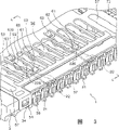
Fig. 1 be a better embodiment of the present invention card connector finish stereogram.
Fig. 2 is the exploded perspective view of the card connector of a better embodiment of the present invention.
Fig. 3 is near the local amplification stereogram in side, front side of the card connector of a better embodiment of the present invention.
Fig. 4 is the 4-4 line profile of Fig. 3.
Fig. 5 is the 4-4 line profile of Fig. 2, shows that IC-card to be ready being inserted into the state of card receiving space.
Embodiment
1. construct
Fig. 1 to Fig. 3 is the stereogram of the card connector of better embodiment of the present invention.Fig. 1 is the stereogram of finishing of this card connector, and Fig. 2 is an exploded perspective view, and Fig. 3 is near the local amplification profile the side, front side.
1-1. insulation shell
When open rear side surface 32 was seen, the side surface in left side was provided with: the used assembling space 137 (also can be arranged on the side surface on right side) of plug control member, for example cartridge ejector 71, pin 72, spring 73 that is used for assembling IC-card.The place ahead at this assembling space 137 is provided with: from the inner wall part on the front side surface 37 of insulation shell 3 towards assembling space extend, the positioning cylinder projection 138 of ammunition feed spring 73 location usefulness, on the other hand, be provided with on the rear side surface of assembling space 137: the location, an end 721 of the pin 72 that will vertically extend, make it the semicircle hang part 39 that can rotate freely at predetermined angular range.Be assembled on this positioning cylinder projection 138 with the mode that is enclosed within positioning cylinder projection 138 outsides a end 731 spring 73, and overcome the elastic force of spring 73 and the other end 733 of spring 73 is inserted the spring patchhole 711 that is arranged on cartridge ejector 71 1 ends, end 721 with pin 72 is configured on the semicircle hang part 39 again, and the other end 723 of pin 72 is configured in slidably is located at around cartridge ejector 71 another distolateral heart type slide connecting parts 712, form the driving push-pull structure of IC-card thus.The push-pull structure of this pattern just often used in the past, and the insider understands very much, so do not remake further bright.
1-2. metal shell
Metal shell 5 for example is that the sheet metal that stainless steel is such carries out stamping-out processing, carries out that the bending process manufacturing comes out again.So its processing is easier to carry out.
Metal shell 5 covers the outside of insulation shell 3.Metal shell 5 generally is used for intercept impacting or as screen, and the present invention also is used for the ground connection of IC-card.For ground connection effectively, metal shell 5 preferably and earth terminal 22 similarly be connected to ground wire 6.Can similarly carry out with substrate circuit 64 with substrate circuit 61 with terminal with being connected of ground wire 6 earth terminal 22 ground connection via metal shell.
Expose in order to make contact terminal 21,22 on the front side surface 51 of metal shell 5, and its substantial middle partly is open.Similarly, its rear side surface 52 is in order to insert for IC-card, and is roughly all open.On the other hand, its left and right sides surface 53 is closing state in fact.On these side surfaces 51 to 53,, be corresponding to the jut 34 on the tool inclined plane of insulation shell 3 and rectangle hang part 35 and suitably be provided with fixing hole 54 and fixed protrusion 55 for metal shell 5 is fixed on insulation shell 3.
Rear in the upper surface both sides of metal shell 5 for the card that will be inserted into card receiving space 36 is fixed, has been cut and is formed big or small two groups of cards and keep displacement portion 56A, B by the part of metal shell 5 is accommodated side to card.Keep displacement portion 56 to push down the card that is inserted into card receiving space 36 with this card, can prevent that IC-card from coming off at upper and lower.
The place ahead in the upper surface both sides of metal shell 5 is assembled in spring 73 members such as grade of insulation shell 3 for the ease of taking-up, is provided with the taking-up hole 57 of rectangle.On the top of the assembling space 137 of the particularly insulation shell 3 of metal shell 5 upper surfaces, in order to push the pin 72 that is configured in assembling space 137 from the top, cut and form pin and keep with displacement portion 58 by the part of metal shell 5 is accommodated side to card.
At the upper surface front side of metal shell 5, metal shell 5 is cut into breach and forms with each contact terminal 21,22 keep out of the way hole 59 one to one.When IC-card inserts card receiving space 36 and makes the signal terminal 21 of card connector or earth terminal 22 when upper position moves, the signal terminal 21 of these displacements or earth terminal 22 near the leading section 221 of top, just keep out of the way the outside of card receiving space 36 by keeping out of the way hole 59.
1-3. ground strip
Form two ground strips 60 by a part that makes metal shell 5.Above-mentioned keep out of the way the summary center that hole 59 just is arranged on this ground strip 60.The ground strip 60 whole slightly ring-types of rectangle that form.
These ground strips 60 are made the state that exposes at card receiving space 36 side direction card receiving spaces 36 at least.As a result, ground strip 60 can directly contact with earth terminal 22.Ground strip 60 is by being connected IC-card with the contact of this earth terminal 22 with ground wire 6.
By bending near the leading section, make leading section 61 integral body of ground strip 60 be positioned at the below.At the front end of leading section 61, by the rolling curved surface shape protuberance of more giving prominence to 62 that has been processed to form towards the below.Ground strip 60 is by this curved surface shape protuberance 62, and often (being that IC-card inserts when blocking receiving space 36 at least) directly contacts with earth terminal 22.
1-4. card restrictions
Near the root of ground strip 60, form card restrictions 63 by a part that makes metal shell 5.The card restrictions 63 towards the inboard of keeping out of the way hole 59 and to the card receiving space 36 side-prominent.Particularly, near the below bend 630 its front end is configured in above-mentioned vertical direction zone.Why will block the correspondence position that restrictions 63 is configured in ground strip 60, be for card restrictions 63 is only contacted with the lip-deep grounding parts of IC-card.In other words, be exactly in order not contact with the signal contact site.If card restrictions 63 contacts with the signal contact site, have the generation risk of short-circuits.
This card restrictions 63 mainly contains two effects.The one, the scope that the restriction IC-card lifts towards the top when IC-card is inserted into card connector, prevent the excessive deformation of contact terminal 21,22 or ground strip 60 thus, the 2nd, make IC-card more reliable by above-mentioned restriction with being connected of earth terminal 22 (signal terminal 21 is too).The latter acts on and can further narrate in the back.
1-5. earth terminal
As mentioned above, contact terminal has 22 two kinds of signal terminal 21 and earth terminals, is that the center illustrates with earth terminal 22 here.Signal terminal 21 is identical with general structure.But, it is that function is different that earth terminal 22 also can be regarded as with signal terminal 21, and structure is actual identical.
Earth terminal 22 is made of fixed part 221, installation portion 224, movable part 225.Fixed part 221 is to be fixed on part on the substrate by welding manner, is connected to ground wire 6 by terminal with substrate circuit 61.Installation portion 224 is installed in vertical arrangement groove set on insulation shell 3 outer surfaces perpendicular to fixed part 221 configurations.Movable part 225 is perpendicular to 224 configurations of this installation portion, and the base portion that is linked to installation portion 224 is pressed into after being inserted into the contact terminal aligning section 38 of insulation shell 3, fixing.
Obviously, the bearing of trend of the bearing of trend of operation strip 225 and above-mentioned ground strip 60, to be that IC-card inserts the direction of card receiving space 36 opposite.As mentioned above, in the present embodiment, movable part 225 is opposite each other with the bearing of trend of ground strip 60, even but in this occasion, as mentioned above, because the hole of keeping out of the way that the free end side of movable part 225 can be kept out of the way ground strip 60, so in fact movable part 225 can not interfere with each other with ground strip 60, the result can guarantee the length of spring leaf of movable part 225, also can guarantee its elasticity.
Near the front end of movable part 225, by the crooked termination contact portion 222 that forms towards the below.When IC-card is inserted into card connector, make physical property with the ground strip 60 of IC-card near the bottom of this termination contact portion 222 and electric property contacts.From the bottom surface 40 of card receiving space 36 to the distance A of this termination contact portion 222 less than from the bottom surface 40 to the below bend 630 of card restrictions apart from B, so before blocking restrictions 63 and the grounding parts 91 of IC-card contacts, the grounding parts 91 of IC-card must be connected with earth terminal 22
Portion's 223 integral body are bent into shape for lugs a little near the centre of movable part 225, and near the upper surface its top contacts with the curved surface shape protuberance 62 of ground strip 60.This contact is adjusted to: before IC-card inserts card connector, be less contact pressure, then corresponding earth terminal 22 after the insertion towards above elastic displacement and become bigger contact pressure.Whether contacted before IC-card inserts as for movable part 225 and ground strip 60 at this unimportant, as long as after IC-card inserts, they really (directly) contact and get final product.In other words, movable part 225 with ground strip 60 if before IC-card inserts, just contact, their contact force is increased, and, after IC-card inserts, just become reliable state of contact so if before IC-card inserts, do not contact.Why be adjusted to IC-card and insert preceding less contact pressure, be because if ground strip 60 is too big for the contact pressure of earth terminal 22, can cause movable part 225 to be out of shape downwards owing to the backflow heat in the hot environment used when card connector is made because of the contact pressure of ground strip 60.
2. action
At Fig. 4, Fig. 5 is respectively the 4-4 profile of Fig. 3.Fig. 5 shows the state that IC-card is being inserted into card receiving space 36.As shown in Figure 5, on IC-card, the lip-deep grounding parts 91 of IC-card (the signal contact site too) at the thickness direction of IC-card a shade below periphery (bottom surface 40 sides to card receiving space 36 are recessed).
When IC-card 9 is inserted into card receiving space 36, respond this insert action (automatically), the lip-deep grounding parts 91 of IC-card just directly contacts with the termination contact portion 222 of movable part 225 in a wherein side of thickness (226) direction of earth terminal movable part 22, make thus movable part 225 in its thickness 226 directions to the zone displacement of above-mentioned vertical direction, portion 223 contacted with the curved surface shape protuberance 62 direct (positively) of ground strip 60 at the opposite side of thickness (226) direction of earth terminal movable part 22 near this displacement made the centre of movable part 225.As a result, the grounding parts 91 of IC-card is electrically connected with metal shell 5 indirectly via earth terminal 22, the grounding parts 91 of IC-card not only with earth terminal 22, also be connected to ground wire by metal shell 5.Because the part of contact terminal 22 is used as earth terminal,, earth terminal is contacted really and stably with IC-card contact site 91 here, so can not produce any obstruction for insertion, the pull action of card.
Prior art generally be earth terminal 22 only by more elongated route, be that terminal is connected to ground wire 6 with substrate circuit 61 (with reference to Fig. 1), earth terminal 22 of the present invention not only with terminal with substrate circuit 61, and with have bigger regional 65 metal shell 5 than this terminal with substrate circuit 61 and be connected, so have better ground connection effect than prior art.And, thus, also can obtain more effective ground connection effect because this earth terminal 22 directly contacts with metal shell 5.Say again, though metal shell 5 final still by with terminal with the same thinner route of substrate circuit 61, be that metal shell is connected to ground wire 6 with substrate circuit 64, but not as existing mode, just to be directly connected to substrate circuit 64, so its ground connection effect is very good from earth terminal 22.As mentioned above, the present invention contacts with the direct of metal shell 5 by earth terminal 22, can lower the impedance of the grounding parts 91 of IC-card effectively, and, therefore can suppress generating noise effectively by this structure because the grounding parts 91 of IC-card is covered by metal earth terminal 22 or ground strip 60 all the time in its vertical direction zone.
Other
In the above-described embodiment, ground strip 60 is to extend along the direction that IC-card is extracted from card receiving space 36, but also can be inserted into the direction extension of card receiving space 36 on the contrary along card.Metal shell 5 preferably is connected with ground wire, but also is not to be connected with ground wire, can not obtain the ground connection effect even be not connected also with ground wire.And, the shape of the card that uses on card connector of the present invention is not particularly limited, as long as be arranged with grounding parts in its surface.And grounding parts, not necessarily to be positioned at the surface of card, also can be the back side.By above-mentioned structure of the present invention,, all can obtain the ground connection effect with above-mentioned method even grounding parts is on surface, the back side or the two sides of card.
Utilizability on the industry
The present invention can be widely applicable for the general card connector with metal shell.
Claims (8)
1. card connector, have: the metal shell that has disposed the insulation shell of signal terminal and earth terminal and covered this insulation shell outside, above-mentioned metal shell is connected with ground wire, form the card receiving space by above-mentioned insulation shell and above-mentioned metal shell, be used for making the row that sticks into that disposes signal contact site and grounding parts from the teeth outwards to plug, when above-mentioned card being inserted into above-mentioned card receiving space, the lip-deep signal contact site of above-mentioned card contacts with earth terminal with the signal terminal of above-mentioned insulation shell respectively with grounding parts, it is characterized by:
The movable part of above-mentioned earth terminal is positioned at the vertical direction zone of the lip-deep grounding parts of above-mentioned card that is inserted into above-mentioned card receiving space,
The part of above-mentioned metal shell at the thickness direction of the movable part of above-mentioned earth terminal being positioned at the zone of above-mentioned vertical direction with the partly overlapping state of the movable part of above-mentioned earth terminal,
When above-mentioned card being inserted in above-mentioned card receiving space, the lip-deep grounding parts of above-mentioned card contacts with the movable part of earth terminal, make the movable part of above-mentioned earth terminal do displacement to above-mentioned vertical direction zone, the contact pressure increase of the movable part that makes the above-mentioned earth terminal after this displacement between the part of above-mentioned vertical direction zone and above-mentioned metal shell at above-mentioned thickness direction.
2. card connector, have: the metal shell that has disposed the insulation shell of signal terminal and earth terminal and covered this insulation shell outside, above-mentioned metal shell is connected with ground wire, form the card receiving space by above-mentioned insulation shell and above-mentioned metal shell, be used for making the row that sticks into that disposes signal contact site and grounding parts from the teeth outwards to plug, when above-mentioned card being inserted into above-mentioned card receiving space, the lip-deep signal contact site of above-mentioned card contacts with earth terminal with the signal terminal of above-mentioned insulation shell respectively with grounding parts, it is characterized by:
The movable part of above-mentioned earth terminal is positioned at the vertical direction zone of the lip-deep grounding parts of above-mentioned card that is inserted into above-mentioned card receiving space,
The part of above-mentioned metal shell at the thickness direction of the movable part of above-mentioned earth terminal being positioned at the zone of above-mentioned vertical direction with the partly overlapping state of the movable part of above-mentioned earth terminal,
When above-mentioned card being inserted in above-mentioned card receiving space, the movable part of above-mentioned earth terminal is in above-mentioned thickness direction one side, contact with the lip-deep grounding parts of above-mentioned card in above-mentioned vertical direction zone, and directly contacts with the part of above-mentioned metal shell at the opposite side of above-mentioned thickness direction, in that above-mentioned vertical direction is regional.
3. card connector as claimed in claim 1 or 2 is characterized by: above-mentioned metal shell is connected with ground wire, and the movable part of above-mentioned earth terminal can be made elastic displacement in above-mentioned vertical direction zone.
4. card connector as claimed in claim 1 or 2 is characterized by: the part of above-mentioned metal shell is extended along the direction that above-mentioned card is extracted out from above-mentioned card receiving space in above-mentioned vertical direction zone.
5. card connector as claimed in claim 1 or 2 is characterized by: the part of above-mentioned metal shell is extended along the direction that above-mentioned card is inserted into above-mentioned card receiving space in above-mentioned vertical direction zone.
6. card connector as claimed in claim 4 is characterized by: the movable part of above-mentioned earth terminal extends along the direction opposite with the bearing of trend of the part of above-mentioned metal shell in above-mentioned vertical direction zone.
7. card connector as claimed in claim 5 is characterized by: the movable part of above-mentioned earth terminal extends along the direction opposite with the bearing of trend of the part of above-mentioned metal shell in above-mentioned vertical direction zone.
8. card connector as claimed in claim 1 or 2 is characterized by: another part of above-mentioned metal shell is side-prominent to above-mentioned card receiving space one in above-mentioned vertical direction zone.
Applications Claiming Priority (2)
| Application Number | Priority Date | Filing Date | Title |
|---|---|---|---|
| JP2003368397A JP3816914B2 (en) | 2003-10-29 | 2003-10-29 | Card connector |
| JP2003368397 | 2003-10-29 |
Publications (2)
| Publication Number | Publication Date |
|---|---|
| CN1612427A CN1612427A (en) | 2005-05-04 |
| CN1324768C true CN1324768C (en) | 2007-07-04 |
Family
ID=34420151
Family Applications (1)
| Application Number | Title | Priority Date | Filing Date |
|---|---|---|---|
| CNB2004100899127A Expired - Fee Related CN1324768C (en) | 2003-10-29 | 2004-10-29 | Card connector |
Country Status (6)
| Country | Link |
|---|---|
| US (1) | US7011533B2 (en) |
| EP (1) | EP1528638A3 (en) |
| JP (1) | JP3816914B2 (en) |
| KR (1) | KR20050040810A (en) |
| CN (1) | CN1324768C (en) |
| TW (1) | TWI248235B (en) |
Cited By (1)
| Publication number | Priority date | Publication date | Assignee | Title |
|---|---|---|---|---|
| CN104600508A (en) * | 2013-10-30 | 2015-05-06 | Smk株式会社 | Card connector |
Families Citing this family (28)
| Publication number | Priority date | Publication date | Assignee | Title |
|---|---|---|---|---|
| JP4141362B2 (en) * | 2003-09-29 | 2008-08-27 | アルプス電気株式会社 | Card adapter |
| TWM253081U (en) * | 2003-11-18 | 2004-12-11 | Hon Hai Prec Ind Co Ltd | Card connector |
| JP4376075B2 (en) * | 2004-01-26 | 2009-12-02 | モレックス インコーポレイテド | Card connector |
| US7479020B2 (en) * | 2004-11-22 | 2009-01-20 | Visteon Global Technologies, Inc. | Electronic control module having an internal electric ground |
| TWI334244B (en) * | 2006-04-24 | 2010-12-01 | Hon Hai Prec Ind Co Ltd | Electrical card connector |
| CN100466385C (en) * | 2006-05-31 | 2009-03-04 | 富士康(昆山)电脑接插件有限公司 | Electronic card connector |
| JP4906523B2 (en) * | 2007-01-25 | 2012-03-28 | 富士通コンポーネント株式会社 | Card connector |
| JP4933293B2 (en) * | 2007-02-09 | 2012-05-16 | 日本圧着端子製造株式会社 | Card connector |
| CN101409392B (en) * | 2007-10-09 | 2011-06-15 | 富士康(昆山)电脑接插件有限公司 | Connector for electronic card |
| CN201112846Y (en) * | 2007-10-12 | 2008-09-10 | 富士康(昆山)电脑接插件有限公司 | Electric connector |
| US20090111306A1 (en) * | 2007-10-31 | 2009-04-30 | Compal Electronics, Inc. | Electrical connector |
| JP5035008B2 (en) * | 2008-02-20 | 2012-09-26 | ミツミ電機株式会社 | Card connector |
| JP5147657B2 (en) * | 2008-11-25 | 2013-02-20 | モレックス インコーポレイテド | Card connector |
| CN201374415Y (en) * | 2009-02-27 | 2009-12-30 | 富士康(昆山)电脑接插件有限公司 | Electronic card connector |
| JP5327461B2 (en) * | 2009-05-13 | 2013-10-30 | 第一精工株式会社 | Connector device |
| JP5402462B2 (en) * | 2009-09-24 | 2014-01-29 | 富士通株式会社 | Card connector and electronic device having the same |
| CN103208708A (en) * | 2012-01-13 | 2013-07-17 | 富士康(昆山)电脑接插件有限公司 | Electric coupler |
| CN202797539U (en) * | 2012-07-25 | 2013-03-13 | 富士康(昆山)电脑接插件有限公司 | Electronic-card connector |
| US8992263B2 (en) * | 2012-08-01 | 2015-03-31 | National Instruments Corporation | Serial bus receptacle with exterior socket clamping |
| JP5516914B2 (en) * | 2012-11-26 | 2014-06-11 | Smk株式会社 | Card connector |
| CN203288875U (en) * | 2013-04-18 | 2013-11-13 | 富士康(昆山)电脑接插件有限公司 | Electronic card connector |
| CN203288877U (en) * | 2013-04-26 | 2013-11-13 | 富士康(昆山)电脑接插件有限公司 | Electronic card connector |
| JP5852056B2 (en) * | 2013-06-28 | 2016-02-03 | タイコエレクトロニクスジャパン合同会社 | Card connectors and contacts |
| CN203690610U (en) * | 2013-11-05 | 2014-07-02 | 富士康(昆山)电脑接插件有限公司 | Electric card connector |
| JP6656808B2 (en) * | 2015-02-17 | 2020-03-04 | ヒロセ電機株式会社 | Assembly of electrical connector and flexible board |
| TWI612730B (en) * | 2015-05-22 | 2018-01-21 | 格稜股份有限公司 | High speed electrical connector |
| EP4156421A1 (en) | 2015-12-14 | 2023-03-29 | Molex, LLC | Backplane connector omitting ground shields and system using same |
| US9881650B1 (en) * | 2016-12-26 | 2018-01-30 | Western Digital Technologies, Inc. | Connector mitigating crosstalk for high speed communication |
Citations (5)
| Publication number | Priority date | Publication date | Assignee | Title |
|---|---|---|---|---|
| US5890917A (en) * | 1995-08-11 | 1999-04-06 | Hirose Electric Co., Ltd. | PC card socket connector and PC card with same |
| US6227880B1 (en) * | 1999-12-14 | 2001-05-08 | Hon Hai Precision Ind. Co., Ltd. | Stacked electrical connector with a single grounding device |
| US6544071B1 (en) * | 2001-12-24 | 2003-04-08 | Hon Hai Precision Ind. Co., Ltd. | Liquid crystal display connector |
| CN2563767Y (en) * | 2002-07-25 | 2003-07-30 | 莫列斯公司 | Electronic card connector |
| CN2574241Y (en) * | 2002-09-17 | 2003-09-17 | 莫列斯公司 | Electric connector |
Family Cites Families (9)
| Publication number | Priority date | Publication date | Assignee | Title |
|---|---|---|---|---|
| US5478260A (en) * | 1994-07-29 | 1995-12-26 | The Whitaker Corporation | Grounding for electrical connectors |
| TW383950U (en) * | 1998-12-28 | 2000-03-01 | Hon Hai Prec Ind Co Ltd | Combination of electrical connector |
| US6074223A (en) * | 1999-04-01 | 2000-06-13 | Hon Hai Precision Ind. Co., Ltd. | Compact flash card having a grounding tab |
| TW481385U (en) * | 2000-11-17 | 2002-03-21 | Hon Hai Prec Ind Co Ltd | Stacked type electronic card connector |
| TW531942B (en) * | 2001-03-15 | 2003-05-11 | Sumitomo Wiring Systems | Connector |
| US6739884B2 (en) * | 2001-05-23 | 2004-05-25 | Samtec, Inc. | Electrical connector having a ground plane with independently configurable contacts |
| JP2003059557A (en) * | 2001-08-08 | 2003-02-28 | Japan Aviation Electronics Industry Ltd | Connector for compact card |
| TW581338U (en) * | 2002-05-23 | 2004-03-21 | Molex Taiwan Ltd | Head structure of electronic card connector |
| US6773275B1 (en) * | 2003-08-15 | 2004-08-10 | Kye Systems Corp. | Connector with static electricity draining mechanism |
-
2003
- 2003-10-29 JP JP2003368397A patent/JP3816914B2/en not_active Expired - Fee Related
-
2004
- 2004-10-20 EP EP04024881A patent/EP1528638A3/en not_active Withdrawn
- 2004-10-21 US US10/969,356 patent/US7011533B2/en not_active Expired - Fee Related
- 2004-10-28 TW TW093132783A patent/TWI248235B/en not_active IP Right Cessation
- 2004-10-29 KR KR1020040087402A patent/KR20050040810A/en not_active Application Discontinuation
- 2004-10-29 CN CNB2004100899127A patent/CN1324768C/en not_active Expired - Fee Related
Patent Citations (5)
| Publication number | Priority date | Publication date | Assignee | Title |
|---|---|---|---|---|
| US5890917A (en) * | 1995-08-11 | 1999-04-06 | Hirose Electric Co., Ltd. | PC card socket connector and PC card with same |
| US6227880B1 (en) * | 1999-12-14 | 2001-05-08 | Hon Hai Precision Ind. Co., Ltd. | Stacked electrical connector with a single grounding device |
| US6544071B1 (en) * | 2001-12-24 | 2003-04-08 | Hon Hai Precision Ind. Co., Ltd. | Liquid crystal display connector |
| CN2563767Y (en) * | 2002-07-25 | 2003-07-30 | 莫列斯公司 | Electronic card connector |
| CN2574241Y (en) * | 2002-09-17 | 2003-09-17 | 莫列斯公司 | Electric connector |
Cited By (1)
| Publication number | Priority date | Publication date | Assignee | Title |
|---|---|---|---|---|
| CN104600508A (en) * | 2013-10-30 | 2015-05-06 | Smk株式会社 | Card connector |
Also Published As
| Publication number | Publication date |
|---|---|
| JP2005135667A (en) | 2005-05-26 |
| US7011533B2 (en) | 2006-03-14 |
| CN1612427A (en) | 2005-05-04 |
| TW200515646A (en) | 2005-05-01 |
| US20050095917A1 (en) | 2005-05-05 |
| JP3816914B2 (en) | 2006-08-30 |
| EP1528638A2 (en) | 2005-05-04 |
| TWI248235B (en) | 2006-01-21 |
| EP1528638A3 (en) | 2008-06-04 |
| KR20050040810A (en) | 2005-05-03 |
Similar Documents
| Publication | Publication Date | Title |
|---|---|---|
| CN1324768C (en) | Card connector | |
| CN1057877C (en) | Electrical connector, housing and contact | |
| CN1192463C (en) | Connector for printed wiring board | |
| CN1097329C (en) | Lockable electrical connector | |
| CN2699530Y (en) | Electric connector | |
| CN2433747Y (en) | Socket connector | |
| CN2886841Y (en) | Electric connector | |
| US20070197073A1 (en) | Electrical connector with reliable structure and method for making the same | |
| EP0175868A2 (en) | Jack and connector | |
| JP3360178B2 (en) | Electrical connector having integral support structure | |
| CN1883083A (en) | Connector | |
| CN1282284C (en) | Method for assembling electrical connector | |
| CN1738100A (en) | Card connector | |
| CN1360367A (en) | Electric connector | |
| US11764513B2 (en) | Electrical connector and transmission wafer thereof | |
| CN2724239Y (en) | Electric connector | |
| US6000955A (en) | Multiple terminal edge connector | |
| EP1418646B1 (en) | Electrical connector with small pitch contact arrangement | |
| US6129564A (en) | Card connector | |
| CN1638197A (en) | Electrical connector and plug-in connection | |
| CN2862397Y (en) | Electric connector assembly | |
| US7048558B2 (en) | Memory card connector | |
| CN2261096Y (en) | Clamping-fringe connector | |
| JP2849600B2 (en) | Electrical connector | |
| CN2660711Y (en) | Terminal of electrical connector |
Legal Events
| Date | Code | Title | Description |
|---|---|---|---|
| C06 | Publication | ||
| PB01 | Publication | ||
| C10 | Entry into substantive examination | ||
| SE01 | Entry into force of request for substantive examination | ||
| C14 | Grant of patent or utility model | ||
| GR01 | Patent grant | ||
| C17 | Cessation of patent right | ||
| CF01 | Termination of patent right due to non-payment of annual fee |
Granted publication date: 20070704 Termination date: 20091130 |