CN1319242A - High-voltage fuse and power distribution network - Google Patents
High-voltage fuse and power distribution network Download PDFInfo
- Publication number
- CN1319242A CN1319242A CN99811304A CN99811304A CN1319242A CN 1319242 A CN1319242 A CN 1319242A CN 99811304 A CN99811304 A CN 99811304A CN 99811304 A CN99811304 A CN 99811304A CN 1319242 A CN1319242 A CN 1319242A
- Authority
- CN
- China
- Prior art keywords
- fuse
- shell
- voltage fuse
- coil
- voltage
- Prior art date
- Legal status (The legal status is an assumption and is not a legal conclusion. Google has not performed a legal analysis and makes no representation as to the accuracy of the status listed.)
- Pending
Links
Images


Classifications
-
- H—ELECTRICITY
- H01—ELECTRIC ELEMENTS
- H01H—ELECTRIC SWITCHES; RELAYS; SELECTORS; EMERGENCY PROTECTIVE DEVICES
- H01H85/00—Protective devices in which the current flows through a part of fusible material and this current is interrupted by displacement of the fusible material when this current becomes excessive
- H01H85/02—Details
-
- H—ELECTRICITY
- H01—ELECTRIC ELEMENTS
- H01F—MAGNETS; INDUCTANCES; TRANSFORMERS; SELECTION OF MATERIALS FOR THEIR MAGNETIC PROPERTIES
- H01F27/00—Details of transformers or inductances, in general
- H01F27/40—Structural association with built-in electric component, e.g. fuse
- H01F27/402—Association of measuring or protective means
Abstract
The invention relates to a high-voltage fuse in which a cover plate (2) of a first electrical connection is connected to a separating plate (6) via a fuse element consisting of silver-coated strips (7) in an electrically conductive manner. A reactor is connected to said separating plate, which reactor has a coil (8) enclosing a core which is provided in the form of a solid ferrite bar (9). Said coil connects the separating plate (6) to a cover plate (4) of a second electrical connection in an electrically conductive manner. Alternatively, in order to save space, the fuse element can be arranged in an opening in the hollow core and can be connected to the coil via a return line. Said high-voltage fuse provides a means of connecting branches of a power supply system to a low-voltage line and a means of preventing the distribution of the high-frequency signals used for communication between appliances of one branch to other branches.
Description
Technical field
The present invention relates to claim 1 a kind of high-voltage fuse as described in the preamble.This class fuse is used in the secondary network mainly as the route protection fuse, generally is arranged in transformer station, power distribution station and the terminal block box.This class fuse can cut-off the overcurrent of hundreds of amperage magnitude.In addition, the present invention relates to claim 13 a kind of distribution network as described in the preamble.
Prior art
This class high-voltage fuse of available different size and design parameter on market.For example the sample " fuse of low-tension fuse " of Luo Keweier Automation Co., Ltd (Rockwell Aatomation) is just showed this different class fuses, and they are consistent with the specification of Deutsche industry norm (DIN) DIN 43620 and IEC IEC 269-2-1 on its size.In fact all has very low impedance under whole frequency situations that this class fuse occurs in network.Its function is limited in cut-offfing overcurrent fully.
As everyone knows, because operating process and other influence produce high frequency voltage and electric current, they are by the network bamboo telegraph and may disturb some responsive users in distribution network.Particularly, when for example also carrying out message transmission with high-frequency signal in a certain building by the part of network, the load of network will cause tangible trouble because of High-frequency Interference.
Description of the invention
The present invention is intended to this known class high-voltage fuse of design like this, makes it can intercept and capture above-mentioned that class interference signal to a great extent simultaneously.Because this class high-voltage fuse is with regard to its conventional function, generally be limited in less network range, the network range that particularly is limited in single building or groups of building is connected with other network, and be limited in this class scope usually equally by this Network Transmission information, so this class fuse is easily located, be used for cutting off the High-frequency Interference of above-mentioned scope from other network.
High-voltage fuse of the present invention is design like this, makes it except cut-offfing overcurrent, also can suppress high-frequency signal, the particularly frequency range high-frequency signal between 1 megahertz and 40 megahertzes as far as possible, and such frequency range is mainly used in message transmission.And this class fuse can be designed on the electric master data with size on consistent with a kind of known standard compliant high-voltage fuse at least and make it not do any change just to can be used on plug-in position or other environment.
The advantage that the present invention reached mainly shows: the favourable impedance ratio that also can set up message transmission in the mode of the simple and inexpensive that can imagine in existing device, promptly regulate impedance ratio like this, high-frequency signal is propagated by the big capacity of power supply network be suppressed basically at the Coupling point of single branch line.
Particularly, can obviously reduce high-frequency signal in this way and enter into and also be used for the power supply network of the information of transmitting, and set up a more favourable signal-interference ratio for message transmission.Also can suppress information signal conversely speaking, greatly spreads out of from the undesirable of branch line.So just stop or at least obviously weakened the influence of interference, and reduced undesirable electromagnetic radiation.In the used frequency range of message transmission, the decoupling of different branch lines can repeatedly be utilized this frequency of network, so just can improve the total information capacity of network.Improve the quality of single branch line simultaneously with interior message transmission.
Brief Description Of Drawings
Describe the present invention in detail below in conjunction with the accompanying drawing of only representing an embodiment.Accompanying drawing is represented:
The vertical section of the high-voltage fuse of the present invention of first kind of structural shape during choke that Fig. 1 band is not cut open;
During choke that Fig. 2 band is not cut open corresponding to the cross section of Fig. 1;
Fig. 3 is along cross section that Fig. 1 hatching III-III is cut open;
The vertical section of the high-voltage fuse of the present invention of second kind of structural shape during choke that Fig. 4 band portion is cut open;
Fig. 5 is along cross section that Fig. 4 hatching V-V is cut open;
The vertical section of the strong fuse of the present invention of the third structural shape during choke that Fig. 6 band is not cut open;
The vertical section that Fig. 7 cuts open along hatching VII-VII corresponding to Fig. 6;
Fig. 8 is along cross section that Fig. 6 hatching VIII-VIII is cut open;
The vertical section of the fuse of the present invention of the 4th kind of structural shape during choke that Fig. 9 band is not cut open;
Figure 10 is along cross section that Fig. 9 X-the X hatching is cut open;
Figure 11 is equivalent to the vertical section of Fig. 9, but has the choke of cutting open;
The vertical section of the fuse of the present invention of the 5th kind of structural shape of Figure 12, direct back at the wall that is positioned at the front;
Figure 13 is along cross section that Figure 12 X III-X III hatching is cut open;
Figure 14 is along vertical section that Figure 13 X IV-X IV hatching is cut open;
The vertical section of the high-voltage fuse of the present invention of the 6th kind of structural shape of Figure 15, direct back at the wall that is positioned at the front;
Figure 16 is along cross section that Figure 15 X VI-X VI hatching is cut open;
Figure 17 is along vertical section that Figure 16 X VII-X VII hatching is cut open;
The vertical section of the high-voltage fuse of the present invention of the 7th kind of structural shape of Figure 18, this fuse on its basic structure corresponding to the fuse of the 5th kind of structural shape;
End view shown in Figure 19 Figure 18 arrow X IX;
End view shown in Figure 20 Figure 18 arrow XX;
The vertical section of the high-voltage fuse of the present invention of the 8th kind of structural shape of Figure 21, this fuse on its basic structure corresponding to the fuse of the 6th kind of structural shape;
End view shown in Figure 22 Figure 21 arrow X XII;
End view shown in Figure 23 Figure 18 arrow XX III;
Figure 24 has used the schematic diagram of a power supply network of high-voltage fuse of the present invention.
Implementation method of the present invention
According to first kind of structural shape (Fig. 1~3), high-voltage fuse of the present invention has one and uses electrical insulating material, the roughly rectangular shell 1 that the most handy ceramic becomes, this shell has on vertical opposed two ends with first electrical connector of first cover plate 2 with second electrical connector of second cover plate 4, and the outside of first cover plate 2 and second cover plate 4 has a contact knife 3 and contact knife 5 respectively.The cover plate 2 and 4 that seals this shell 1 for example is formed from aluminium, and contact knife 3 and 5 make with copper alloy and carry out silver-plated.
Enclosure with an electric conducting material for example the dividing plate 6 made of aluminium in vertically, be divided into two sections.At the cover plate 2 of first electric connection and first section of the length between the dividing plate 6 one section fuse is housed, this fuse conduction connects cover plate 2 and dividing plate 6.Fuse is made up of the silver-colored braid over braid 7 of the parallel connection of three arranged in series and is designed in the mode of knowing, and it is being produced under the overcurrent situations, through fusing and turn-off current after certain operate time of depending on current strength by the certain standard characteristic curve.
In one section between the cover plate 4 of the dividing plate 6 of enclosure and second electric connection, arranged a choke.This choke is made up of the iron core of a columnar coil 8 and a perforation, this coil conduction connects dividing plate 6 and cover plate 4, this iron core is then used ferromagnetic material, preferably use electrical insulating material, particularly make, and make a solid pole 9 that is surrounded by coil that is positioned at the axis of coil 8 all around with ferrite.The inductance of this choke is to select like this: in frequency is mains frequency when being about 50 hertz of orders of magnitude, and its impedance is little of can ignoring, and when the high frequency of 1 megahertz to 40 megahertz, its impedance is then very big.
High-voltage fuse can meet the specification 1-3 of Deutsche industry norm (DIN) DIN 432620 on its size, and for example is designed into 400 volts and 400 peaces.This fuse can at any time be used to meet the occasion of the conventional fuse of this standard.
Second kind of structural shape (Fig. 4,5) of high-voltage fuse of the present invention only is with the difference of first kind of structural shape, coil 8 is done smallerly slightly, and iron core is except a rod 9 that is arranged in the coil axis, also has a shell that surrounds this coil 8, this shell is made up of with shell 10a, the 10b that the end of rod 9 is connected two halves, and this two half-shells separates by the annulus gap 11 at a center.This shell has scallop hole 12a, 12b two mutual diametrically contrapositions, that extend on its whole length, coil 8 is connected with cover plate 4 conductions with dividing plate 6 by this scallop hole.
The third structural shape (Fig. 6~8) is to a great extent also corresponding to first kind of structural shape, but is again the cover plate 4 that extends and reach from the cover plate 2 of first electric connection always second electric connection as the iron core that solid pole 9 constitutes basically in the whole length of shell 1 here.Three bullion braid over braids 7 of fuse are arranged around rod 9.The characteristics of this structural shape are to have good especially mechanical stability.
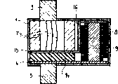
The structure of a kind of modification of the 4th kind of structural shape (Fig. 9~11) expression of high-voltage fuse of the present invention.Here iron core is designed to rod 9 again, and this rod is surrounded by coil 8.But the coil rectangular cross section, rod 9 is then made hollow, and this rod has the central sheath of a perforation in vertically, and fuse is arranged in this sheath.Here fuse is made up of a unique bullion braid over braid 7.Coil 8 separates by the cover plate 2 of the insulating barrier 13 and first electric connection, and silver-colored braid over braid 7 then separates by the cover plate 4 of the insulating barrier 14 and second electric connection.
Silver braid over braid 7 is connected on first cover plate 2 by a hole in first insulating barrier 13.Its other end then is connected with a feedback line 16 that for example constitutes as feedback line by an intermediate plate 15 that is placed on second insulating barrier 14, and this feedback line is got back to an end that is positioned near the coil 8 first cover plate 2 in a groove on rod 9 outsides of silver-colored braid over braid 7.The other end of last coil 8 then is connected with cover plate 4 by a hole in second insulating barrier.That is current path from cover plate 2 by silver-colored braid over braid 7, intermediate plate 15, through feedback line 16 return and again oppositely the back pass through coil 8 to cover plate 4.
The special save space of this structural shape especially can be done very shortly.So, make the specification 00-3 that is equivalent to Deutsche industry norm (DIN) DIN 43620 dimensionally, and can at any time be used to meet the occasion of the conventional high-voltage fuse of this standard.
The 5th kind of structural shape (Figure 12~14) of high-voltage fuse of the present invention on its basic structure corresponding to the 4th kind of structural shape, only coil 8 is arranged in the next door of fuse, and this fuse then is arranged between the contact knife 3 of first electric connection and the intermediate plate 15 and by three parallel silver-colored braid over braids 7 to be formed.Feedback line 16 of intermediate plate 15 usefulness is connected with the end of coil 8 near first electric connection, and the other end of coil 8 then is connected on the cover plate 4 of second electric connection.One insulating barrier 14 is arranged between the latter and intermediate plate 15.Coil 8 surrounds an iron core, and this iron core is insulated layer and surrounds.This iron core can be made a solid pole 9, or is made up of many parallel rods.
Current path from the contact knife 3 of first electric connection by silver-colored braid over braid 7 to intermediate plate 15 and continue by feedback line 16, coils 8, the contact knife 5 by cover plate 4 to second electric connections again.
According to the 6th kind of structural shape, high-voltage fuse of the present invention (Figure 15~17) has the coil 8 and the fuse that the conduct silver braid over braid 7 that is arranged in the next door constitutes that are arranged between the contact knife 3,5, and is structurally similar to the high-voltage fuse of the present invention of the 5th kind of structural shape.Connect its cover plate 2 on the contact knife 3 of first electric connection, this cover plate is connected with intermediate plate 15 by fuse, and this intermediate plate is arranged in the next door of the cover plate 4 of second electric connection at a certain distance.Intermediate plate 15 is connected with the end of coil 8 near the first electric connection connecting plate 2 by feedback line 16, and the other end of this coil then is connected on the cover plate 4 of second electric connection, and this cover plate then supports contact knife 5.
In above-mentioned last two kinds of structural shapes, the size of high-voltage fuse of the present invention surpasses the size of this known class high-voltage fuse, but be only limited to the horizontal size for connection between the contact knife, and other size still the standard size with known this class high-voltage fuse is consistent.So high-voltage fuse of the present invention does not under normal circumstances hinder the use at the standard plug-in position.
According to the 7th kind of structural shape (Figure 18~20), high-voltage fuse of the present invention on its basic structure corresponding to the high-voltage fuse of the 5th kind of structural shape.Carried out the change of some CONSTRUCTED SPECIFICATION only in the drawings.The contact knife 3 of first electric connection carries out machinery with first end plate 17 and is connected with conduction, an end of the fuse shell 18 that this end plate closes electricity consumption insulating material is made, and this shell is then sealed by second end plate 19 at an opposed end.Contain three parallel silver-colored braid over braids 7 in the fuse shell 18, they are connected with second end plate, 19 conductions with first end plate 17.First end plate 17 has an activity indicator on the next door of contact knife 3.Second end plate 19 then is connected with an intermediate plate 15 with screw, and this intermediate plate and feedback line 16 that returns on fuse shell 18 next doors and a piece of cloth are put the Z-shaped parts that constitute an integral body at the connecting plate 21 on first end plate 17 next door.For the mechanical consolidation of high-voltage fuse, first end plate 17 is connected with the connecting plate 22 overlapping screws that carry out that a connecting plate 21 and an electricity consumption insulating material are made.
A coaxial arrangement electricity interior loop 8a and exterior loop 8b in parallel between connecting plate 21 and header board 23.Header board 23 is arranged in the front of second end plate 19 at a certain distance, and is connected with this end plate by the dividing plate 24 that insulating material is made, and at the contact knife 5 from second electric connection of the outside of second end plate 19 supporting.The reason of Bu Zhiing is as follows like this: coil 8a, 8b make with the winding wire of the varnished insulation in essentially rectangular cross section.In order to reach the high number of turn, the long limit radial directed of rectangle when the given cross section.But the radial expansion of winding wire is like this restriction, promptly when coiling, does not allow that winding wire produces that may increase pitch of turn harmful reverses, chap or bending.Like this, although given cross section is limited, reached high electric current ability to bear, electric current is assigned on two coils.
Arranged a ferrite iron core 9 that is surrounded by an insulating case 25 at interior loop 8b with interior, it is fixed by the lid 26 in a hole of a sealing header board 23.Clavate ferrite iron core that need not be solid, also available ferrite tube or the some ferrite spillikins or the tubule that are arranged in parallel.Also the ferrite iron core of available different length carries out balance by lid or with different thickness.
Described high-voltage fuse is applicable to high current strength, and however, its volume is little, mechanical strength is very high and can be used for general plug-in position.Shell that it is made with non-conducting material by one usually, unshowned in the drawings covers, and this shell is reserved on the one hand end face that is made of first end plate 17, connecting plate 22 and connecting plate 21 and the end face that constitutes header board 23 on the other hand.For the ease of inserting plug-in position and taking off fuse from this plug-in position, connecting plate 21 and header board 23 respectively dispose a tension board 27.
According to the 8th kind of structural shape (Figure 21~23), high-voltage fuse of the present invention is equivalent to the high-voltage fuse of the 6th kind of structural shape on its basic structure, there is shown its details.The contact knife 3 of first electric connection here is connected with a header board 23 with screw, this header board then is connected with first end plate 17 with screw, fuse shell 18 is connected on the end plate, and in this shell, be provided with silver-colored braid over braid (not shown), the conduction that these silver-colored braid over braids are set up between first end plate 17 and second end plate 19 connects, and this second end plate seals this shell 18 at an opposed end.First end plate 17 is equipped with activity indicator 20.
The coil arranged alongside dividing plate made from non-conducting material 24, their connect end plate 2 and shut 29.Like this, high-voltage fuse has enough mechanical strengths again and has nothing to do with coil 8, and is adjusted to standard compliant size.On end plate 17,19, connect tension board 27 with screw.
Figure 24 represents a schematic diagram that has used the power supply network of high-voltage fuse of the present invention.From transformer 31-also may be a for example low-voltage line 32 of terminal block box-draw of another kind of breakout, tell many branch lines 33 from this low-voltage line, every branch line all passes through high-voltage fuse 34 of the present invention, and in this fuse back, every branch line is proceeded branch.Single branch line 33 can for example be powered to a building respectively.On every branch line, be connected with transmitter and receiver 35, for example distinguish a programmable logic controller (PLC), and on branch line, connect various instrument (not shown)s, with these instruments can by high-frequency signal for example the carrier frequency between 1 megahertz and 40 megahertzes communicate.Signal is coupled with electric current or inductance mode.Because these signals produce serious decay by high-voltage fuse 34, so they are substantially limited on the independent branch line.Like this, even at band overlapping or very approaching, in the time of consequently certainly will producing the reciprocation of interference, the interference between each branch road can not cause fault yet.For this reason, generally need such prerequisite: transmitter and receiver 35 must synchronous working promptly must send and receive simultaneously.
Claims (13)
1. have a shell made from insulating material (1) and on vertical two opposite ends of this shell, have the high-voltage fuse of first electric connection and second electric connection, conduct electricity connection by a fuse that is arranged in this shell (1), it is characterized by, the conduction between first electric connection and second electric connection connects the choke of connecting with this fuse that is arranged in the shell (1) by and realizes.
2. by the high-voltage fuse of claim 1, it is characterized by, this choke comprises at least one coil (8) and has an iron core made from ferrimagnet especially electrical insulating material that this iron core and coil (8) carry out magnetic coupling.
3. by the high-voltage fuse of claim 2, it is characterized by, this iron core comprises the rod (9) that a velamen coil (8) surrounds.
4. by the high-voltage fuse of claim 2 or 3, it is characterized by, this iron core comprises a shell, and this shell surrounds coil (8) at shell at least in part.
5. by the high-voltage fuse of claim 4, it is characterized by, this shell have two mutual opposed scallop holes (12a, 12b).
6. by claim 4 or 5 high-voltage fuse, it is characterized by, this shell by the air gap of an annular (11) in two shell (10a, 10b).
7. by each high-voltage fuse of claim 1~6, it is characterized by, this fuse and this choke are arranged in the shell (1) in vertically successively.
8. by the high-voltage fuse of claim 7, it is characterized by, enclosure contains the part of this fuse and part that enclosure contains this choke is spaced from each other by the dividing plate of a horizontal expansion (6).
9. by each high-voltage fuse of claim 1~6, it is characterized by, this choke surrounds this fuse.
10. by claim 3 and 9 high-voltage fuse, it is characterized by, rod (9) is hollow, has a sheath that holds this fuse, coil (8) by one be arranged on rod (9) outside, be connected with this fuse with feedback line that this fuse extends in the other direction.
11. by each high-voltage fuse of claim 1~6, it is characterized by, this fuse and this choke be parallel being arranged in parallel in the shell (1) in vertical.
12. by each high-voltage fuse of claim 1~11, it is characterized by, this choke comprise at least two coaxial arrangement bridging coil (8a, 8b).
13. have the power supply network of a plurality of electrical connection branch roads (33), it is characterized by, in each branch road (33), all adorn each high-voltage fuse of a claim 1~11 at input.
Applications Claiming Priority (2)
| Application Number | Priority Date | Filing Date | Title |
|---|---|---|---|
| EP98810964A EP0996137A1 (en) | 1998-09-24 | 1998-09-24 | Power fuse |
| EP98810964.1 | 1998-09-24 |
Publications (1)
| Publication Number | Publication Date |
|---|---|
| CN1319242A true CN1319242A (en) | 2001-10-24 |
Family
ID=8236348
Family Applications (1)
| Application Number | Title | Priority Date | Filing Date |
|---|---|---|---|
| CN99811304A Pending CN1319242A (en) | 1998-09-24 | 1999-09-23 | High-voltage fuse and power distribution network |
Country Status (14)
| Country | Link |
|---|---|
| EP (2) | EP0996137A1 (en) |
| JP (1) | JP2002526888A (en) |
| KR (1) | KR20010079736A (en) |
| CN (1) | CN1319242A (en) |
| AT (1) | ATE221251T1 (en) |
| AU (1) | AU5615399A (en) |
| BR (1) | BR9913105A (en) |
| CA (1) | CA2340772A1 (en) |
| DE (1) | DE59902140D1 (en) |
| ES (1) | ES2178898T3 (en) |
| ID (1) | ID27919A (en) |
| IL (1) | IL142062A0 (en) |
| NO (1) | NO20011508L (en) |
| WO (1) | WO2000019475A1 (en) |
Cited By (1)
| Publication number | Priority date | Publication date | Assignee | Title |
|---|---|---|---|---|
| CN114899060A (en) * | 2022-05-16 | 2022-08-12 | 扬州森源电力科技有限公司 | Fuse for circuit control |
Families Citing this family (5)
| Publication number | Priority date | Publication date | Assignee | Title |
|---|---|---|---|---|
| DE102017126419A1 (en) * | 2017-02-08 | 2018-08-09 | Dehn + Söhne Gmbh + Co. Kg | Fuse for low voltage applications |
| DE102018213522B4 (en) | 2018-08-10 | 2022-06-02 | Siemens Aktiengesellschaft | Fusible link, fuse body, system and method |
| EP3844792B1 (en) * | 2018-12-20 | 2023-01-25 | Siemens Aktiengesellschaft | Fuse having an integrated measuring function |
| EP3867939B1 (en) * | 2018-12-20 | 2023-02-15 | Siemens Aktiengesellschaft | Fuse having an integrated measuring function |
| EP3853878A1 (en) * | 2019-01-16 | 2021-07-28 | Siemens Aktiengesellschaft | Fuse element and fuse |
Family Cites Families (6)
| Publication number | Priority date | Publication date | Assignee | Title |
|---|---|---|---|---|
| DE1836426U (en) * | 1960-11-23 | 1961-08-17 | Blaupunkt Werke Gmbh | FUSE HOLDER FOR SMALL FUSES. |
| GB2060964A (en) * | 1979-10-20 | 1981-05-07 | Swish Prod | Electronic time-based control system |
| FR2471039A1 (en) * | 1979-12-04 | 1981-06-12 | Ferodo Sa | Overheating protector for vehicle air-flap drive motor - has tinned block on coiled conductor which frees contacts when heated |
| DE9201490U1 (en) * | 1992-02-06 | 1993-03-11 | Siemens Ag, 8000 Muenchen, De | |
| EP0639840B1 (en) * | 1993-07-22 | 1996-12-04 | ABBPATENT GmbH | Pressure assembly for converter |
| JPH09330824A (en) * | 1996-06-11 | 1997-12-22 | Nippon Electric Ind Co Ltd | Inductor having fuse function |
-
1998
- 1998-09-24 EP EP98810964A patent/EP0996137A1/en not_active Withdrawn
-
1999
- 1999-03-24 KR KR1020017002800A patent/KR20010079736A/en not_active Application Discontinuation
- 1999-09-23 ES ES99942700T patent/ES2178898T3/en not_active Expired - Lifetime
- 1999-09-23 CN CN99811304A patent/CN1319242A/en active Pending
- 1999-09-23 CA CA002340772A patent/CA2340772A1/en not_active Abandoned
- 1999-09-23 DE DE59902140T patent/DE59902140D1/en not_active Expired - Fee Related
- 1999-09-23 IL IL14206299A patent/IL142062A0/en unknown
- 1999-09-23 EP EP99942700A patent/EP1116252B1/en not_active Expired - Lifetime
- 1999-09-23 WO PCT/CH1999/000454 patent/WO2000019475A1/en not_active Application Discontinuation
- 1999-09-23 JP JP2000572885A patent/JP2002526888A/en active Pending
- 1999-09-23 AU AU56153/99A patent/AU5615399A/en not_active Abandoned
- 1999-09-23 AT AT99942700T patent/ATE221251T1/en not_active IP Right Cessation
- 1999-09-23 BR BR9913105-6A patent/BR9913105A/en not_active IP Right Cessation
- 1999-09-23 ID IDW20010686A patent/ID27919A/en unknown
-
2001
- 2001-03-23 NO NO20011508A patent/NO20011508L/en not_active Application Discontinuation
Cited By (1)
| Publication number | Priority date | Publication date | Assignee | Title |
|---|---|---|---|---|
| CN114899060A (en) * | 2022-05-16 | 2022-08-12 | 扬州森源电力科技有限公司 | Fuse for circuit control |
Also Published As
| Publication number | Publication date |
|---|---|
| IL142062A0 (en) | 2002-03-10 |
| EP1116252A1 (en) | 2001-07-18 |
| ES2178898T3 (en) | 2003-01-01 |
| NO20011508D0 (en) | 2001-03-23 |
| NO20011508L (en) | 2001-03-23 |
| DE59902140D1 (en) | 2002-08-29 |
| AU5615399A (en) | 2000-04-17 |
| ATE221251T1 (en) | 2002-08-15 |
| JP2002526888A (en) | 2002-08-20 |
| KR20010079736A (en) | 2001-08-22 |
| BR9913105A (en) | 2001-05-08 |
| EP0996137A1 (en) | 2000-04-26 |
| WO2000019475A1 (en) | 2000-04-06 |
| EP1116252B1 (en) | 2002-07-24 |
| ID27919A (en) | 2001-05-03 |
| CA2340772A1 (en) | 2000-04-06 |
Similar Documents
| Publication | Publication Date | Title |
|---|---|---|
| CN110289156B (en) | Coil winding, coil module, transmitting device, receiving device, system and terminal | |
| EP0053638B1 (en) | Current mode data or power bus | |
| US4158478A (en) | Coaxial optical fibre cable | |
| US6255935B1 (en) | Coupling capacitor having an integrated connecting cable | |
| AU5615301A (en) | 8,8a-dihydro-indeno(1,2-d)thiazole derivatives, substituted in position 8a, a method for their production and their use as medicaments, e.g. anorectic agents | |
| CN1319242A (en) | High-voltage fuse and power distribution network | |
| CN1298189A (en) | Electromagnetic interference shielding for small magnetic apparatus | |
| CN1020018C (en) | High-voltage voltage transformer | |
| CN201629196U (en) | Insulation pulse type transformer | |
| CZ149699A3 (en) | Inductor | |
| EP0242691B1 (en) | Gas insulated switching apparatus | |
| CN2572527Y (en) | Small change rate SF6 gas insulation current mutual inductor | |
| CN220553353U (en) | Filter | |
| CN219759266U (en) | Environment-friendly modified polypropylene insulation power cable | |
| CA3058026C (en) | A system for wireless power transfer between low and high electrical potential, and a high voltage circuit breaker | |
| CN113130176B (en) | High-voltage harmonic transformer | |
| CN209266159U (en) | A kind of high power DC high pressure generator intermediate-frequency transformer | |
| CN109698043B (en) | Wire for transformer winding and transformer | |
| CN1452816A (en) | Method and system for transmitting data over low-voltage electricity suppy network | |
| KR100468322B1 (en) | Pulse transformer for transmitting and receiving signal | |
| JP2000030545A (en) | Capacitively coupled cable for transmission of signal via high voltage and intermediate voltage electric power line | |
| CN2525663Y (en) | Dry high voltage current mutual inductor | |
| US20220108829A1 (en) | Wire for use in transformer winding and transformer | |
| KR200286805Y1 (en) | Pulse transformer for transmitting and receiving signal | |
| JPS62111529A (en) | Signal transmission equipment utilizing low voltage distribution line |
Legal Events
| Date | Code | Title | Description |
|---|---|---|---|
| C06 | Publication | ||
| PB01 | Publication | ||
| C10 | Entry into substantive examination | ||
| SE01 | Entry into force of request for substantive examination | ||
| C02 | Deemed withdrawal of patent application after publication (patent law 2001) | ||
| WD01 | Invention patent application deemed withdrawn after publication | ||
| REG | Reference to a national code |
Ref country code: HK Ref legal event code: WD Ref document number: 1041365 Country of ref document: HK |