The application is that application number is 00805884.9, the applying date is on February 16th, 2000, be entitled as the dividing an application of application of " fibre distribution frame with pivoting connector panels ".
Description of drawings
Fig. 1 be first embodiment of fibre distribution frame of the present invention forward sight, overlook and right parallax stereogram, its some part illustrates with exploded view, and has removed the Qianmen;
Fig. 2 is the front view of distributing frame shown in Figure 1, and it shows the last Qianmen that is shown in an open position and following Qianmen in the closed position;
Fig. 3 is the right view of distributing frame shown in Figure 1, and it shows in the closed position calling and the Xiamen;
Fig. 4 be one of them distribution frame with outside plant enclosure in the distributing frame shown in Figure 1 forward sight, overlook and right parallax stereogram;
Fig. 5 is the vertical view of distribution frame with outside plant enclosure shown in Figure 4;
Fig. 6 be distribution frame with outside plant enclosure shown in Figure 4 forward sight, overlook and right parallax stereogram, main panel shown in the figure and optical cable access door have been switched to open position;
Fig. 7 is the vertical view of distribution frame with outside plant enclosure shown in Figure 6, and wherein, described main panel and optical cable access door are shown in an open position;
Fig. 8 be described distribution frame with outside plant enclosure forward sight, overlook and right parallax stereogram, its some part is removed, and described main panel is shown in an open position, it shows the fiber channel of several typical;
Fig. 9 be the main casing of described terminal assembly forward sight, overlook and right parallax stereogram;
Figure 10 is the front view of main casing shown in Figure 9;
Figure 11 is the cross-sectional vertical view along the described distributing frame of Fig. 2 center line 11-11 intercepting;
Figure 12 is the cross-sectional vertical view along the described distributing frame of Fig. 2 center line 12-12 intercepting;
Figure 13 is the cross-sectional vertical view along Fig. 2 center line 13-13 intercepting;
Figure 14 be second embodiment of distributing frame of the present invention forward sight, overlook and right parallax stereogram, its some part illustrates with the form of exploded view;
Figure 15 is the front view of distributing frame shown in Figure 14;
Figure 16 is the right view of distributing frame shown in Figure 14;
Figure 17 be one of them distribution frame with outside plant enclosure in the distributing frame shown in Figure 14 forward sight, overlook and right parallax stereogram;
Figure 18 is the vertical view of distribution frame with outside plant enclosure shown in Figure 17;
Figure 19 be distribution frame with outside plant enclosure shown in Figure 17 forward sight, overlook and right parallax stereogram, the main panel shown in the figure has been switched to open position;
Figure 20 is the vertical view of distribution frame with outside plant enclosure shown in Figure 19, and wherein said main panel is shown in an open position;
Figure 21 be distribution frame with outside plant enclosure shown in Figure 17 forward sight, overlook and left parallax stereogram, wherein, described main panel is shown in an open position, it shows the fiber channel of several typical;
Figure 22 be the main casing of distribution frame with outside plant enclosure shown in Figure 17 forward sight, overlook and right parallax stereogram;
Figure 23 is the front view of main casing shown in Figure 22;
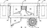
Figure 24 is the vertical view of distributing frame shown in Figure 14;
Figure 25 be the 3rd embodiment of fibre distribution frame of the present invention forward sight, overlook and right parallax stereogram;
Figure 26 be distributing frame shown in Figure 25 forward sight, overlook and right parallax stereogram, it shows each feature with the form of exploded view;
Figure 27 be distributing frame shown in Figure 25 forward sight, overlook and right parallax stereogram, the terminal board frame component shown in the figure is in the orientation opposite with distributing frame shown in Figure 25;
Figure 28 is the stereographic map of the last optical cable snap ring of Figure 25-distributing frame shown in Figure 27;
Figure 29 is the vertical view of optical cable snap ring shown in Figure 28;
Figure 30 be the 4th embodiment of fibre distribution frame of the present invention forward sight, overlook and right parallax stereogram, shown in some of distributing frame be removed, and one of them panel has been switched to open position;
Figure 31 is the front view of distributing frame shown in Figure 30;
Figure 32 be the top of distributing frame shown in Figure 30 forward sight, overlook and right parallax stereogram;
Figure 33 be one of them distribution frame with outside plant enclosure in the distributing frame shown in Figure 30 forward sight, overlook and left parallax stereogram;
Figure 34 be distribution frame with outside plant enclosure shown in Figure 33 forward sight, overlook and left parallax stereogram, the main panel shown in the figure has been switched to open position;
Figure 35 be distribution frame with outside plant enclosure shown in Figure 34 forward sight, overlook and left parallax stereogram, wherein, described main panel is shown in an open position, it shows the fiber channel of several typical;
Figure 36 is shown in Figure 35, have the distribution frame with outside plant enclosure of several typical fiber channel forward sight, overlook and right parallax stereogram;
Figure 37 is with the forward sight of the similar distribution frame with outside plant enclosure of view shown in Figure 35, overlooks and right parallax stereogram, and it shows an optical cable lid protection that is installed on described main panel; Distribution frame with outside plant enclosure shown in Figure 37 is constructed and arranged to the left side that is used for distributing frame shown in Figure 30.
Embodiment
Now see also Fig. 1-Fig. 3, there is shown a preferred embodiment 20 of a kind of framework or distributing frame, be used for that each optical cable to described distributing frame inside splices, termination and management.Fig. 4-Figure 13 shows the further feature of distributing frame 20.The top 22 of distributing frame 20 is formed with a termination and storage area.The bottom 24 of distributing frame 20 is formed with a splice region.The optical cable that comprises one or more individual fibers can enter from an overhead fiber optic cable facility from top to bottom by the top 26 of distributing frame 20 usually, or enters from bottom to top from the sunken bottom plate facility of the bottom 28 that is positioned at distributing frame 20.If optical cable is a termination in advance, each optical cable then directly extends to termination storage area 22.If enter the optical cable of distributing frame 20 and be not termination in advance, each optical cable then extends to splice region 24 to splice mutually with optical cable through termination.Each optical cable extends to termination storage area 22 from splice region 24 then.In termination storage area 22, be provided with a plurality of termination location that touch and use and can be used to and to be connected with terminating optical cables such as other optical cable that connects flexible cord or connect the optical cable through optical cables of termination for those.Adopt to connect optical cable, telecommunication apparatus just can pass through distributing frame 20 cross connection between each termination location.
Distributing frame 20 comprises that one can support the support 30 of a plurality of distribution frame with outside plant enclosure 32.In described preferred embodiment, be provided with the left and right row 34,36 of distribution frame with outside plant enclosure 32.Each row 34,36 in the illustrated embodiment include three independently distribution frame with outside plant enclosure 32a (left side), 32b (right side).
Support 30 also supports an interior framework management-plane 40 between the left and right row 34,36 of distribution frame with outside plant enclosure 32, is used for the unnecessary length that connects optical cable is held systematically and deposited.Preferably, interior framework management-plane 40 comprises a file that is made of a plurality of independently modules or part 40a.All be installed on independent distribution frame with outside plant enclosure 32a, the 32b of support 30 and the independent sector 40a of interior framework management-plane 40 individually by being provided with, these modules can add to support 30 at different time, and can be changed if desired.Equally, customization distributing frame 20 can be arranged on six distribution frame with outside plant enclosure 32a, 32b of those interior framework management-planes 40 that can adopt other fiber management equipment rather than illustrated embodiment in one or more zones of support 30 and the place of three part 40a.
Support 30 also supports a terminal board frame component 44 that is used for holding a plurality of joint plate rails 46.In described preferred embodiment, distributing frame 20 comprises the terminal board frame component 44 of two vertical stacks.Each joint plate rail includes the structure that is used for holding the end of a plurality of optical cables and holds the independent joint between each end of cable.Can adopt various terminal plate rail 46.The example of some joint plate rails has been shown, this patent usefulness as a reference cited in this article in the U.S. Patent No. of transferring the possession of 09/158,182 application on September 21st, 1998, common.
Support 30 also supports a horizontal cable drum rack 50 that is positioned between termination storage area 22 and the splice region 24.Horizontal plate rail 50 can support those at the connection optical cable that extends on the front portion of distributing frame 20, between the left and right row 34,36 of distribution frame with outside plant enclosure 32 and interior framework management-plane 40.Plate rail 50 also supports the connection optical cable that extends between those telecommunication apparatus in distributing frame 20 and other distributing frame 20 or adjacent domain.
Distributing frame 20 preferably includes the following Qianmen 56,58 of the last Qianmen 52,54 of hinged installation and hinged installation to protect each optical cable, connector, breakout box and joint plate rail.Last Qianmen 52,54 can pivot around the longitudinal axis.Following Qianmen 56,58 can pivot around transverse axis.Each preferably includes one or more breech locks 59 to hold them in off-position.
Support 30 also supports two optical cable guides 60,62 longitudinally, and a described optical cable guide is arranged on each side of support 30. Optical cable guide 60,62 comprises a plurality of finger pieces that separate each other 65, and the vertical side that they can make optical cable pass through each guide inserts the inside of each optical cable guide 60,62.In illustrated embodiment, each optical cable guide 60,62 also comprises the articulated slab 64 of the part finger piece that is used for forming Qianmen 52,54.Each optical cable guide 60,62 is preferably made several segments, as the parts of the brick pattern of distributing frame 20 design.
Consider the convenience of assembling and the versatility of use, the independent member that each member of formation distributing frame 20 is more preferably kept together by fastener.For example, in illustrated embodiment, distribution frame with outside plant enclosure 32, interior framework management-plane 40, terminal board frame component 44, cable drum rack 50 and optical cable guide 60,62 separate with support 30.
Distributing frame 20 is formed with the various access ports that make optical cable enter distributing frame 20.The pit of the stomach 66 can make each optical cable enter distributing frame from bottom to up from a heaving floor facility in the bottom 28, of distributing frame 20.Central passage 68 can make each optical cable pass through each independently joint plate rail 46.Being provided with some setting fastenings 69 (Figure 11 and Figure 12) is to be fixed on the distributing frame 20 will import optical cable securely.Central opening 70 in cable drum rack 50 couples together splice region 24 and termination storage area 22.Near the top 26 of distributing frame 20, access port is provided by rear center's opening 72 or two open tops 74,76, and an open top is arranged on each top distribution frame with outside plant enclosure 32.For optical cable is carried out pre-termination, can make each optical cable directly pass open top 74,76, to terminate in the distribution frame with outside plant enclosure 32.For the optical cable that the good optical cable of those and termination splices mutually, after-opening 72 leads to one and extends downward the back vertical passage 78 and the setting fastening 69 of splice region 24, so that at joint plate rail 46 places terminating optical cables is spliced.
Now see also Fig. 1, Fig. 2 and Figure 13, each part 40a of interior framework management-plane 40 includes: a core 80, two extend forward and opposed side 82,84, and the center spool 86 that one or morely vertically separates, extends forward from core 80.Spool 86 is to be used for depositing the unnecessary length that connects optical cable (such as the connection optical cable that extends) between the left and right row 34,36 of distribution frame with outside plant enclosure 32.Preferably, each part 40a includes two spools, like this, also has the cable storage ability when only being provided with a part.
Now see also Fig. 1, Fig. 2 and Figure 12, each terminal board frame component 44 includes: main horizontal supports 90, one a main back supporting member 91, a plurality of partition wall 92 and a plurality of scroll rack or supporting member 94 that is used for supporting each joint plate rail 46, described joint plate rail has the outer peripheral edges of a circle.In illustrated embodiment, described partition wall 92 is vertically extending.Main horizontal supports 90 has a uncovered middle part 90a who is used for fiber channel.Be provided with an optical cable guiding finger piece 96 and an optical cable setting fastening 98, so that each optical cable is firmly held on the distributing frame 20.So just joint plate rail 46 can be disassembled from terminal board frame component 44, and the end that makes optical cable debatching from the joint plate rail 46 gets off, and can not make optical cable excessive stress occur or move.In illustrated embodiment, partition wall 92 is vertically extending.In other embodiments, described partition wall can be with respect to vertical direction or or even with respect to horizontal direction at angle.Though each the terminal board frame component 44 shown in the figure is the parts as distributing frame 20,, if desired, each joint plate rail can be covered up with distributing frame 20 to be separated.
Now see also Fig. 1-Fig. 3 and Figure 11, horizontal cable drum rack 50 comprises a main horizontal part 99, described main horizontal part comprises: central opening 70, two mutually opposed on each side of central opening 70 and upwardly extending curved optical cable guides 101, and a center cover cap 102 that is positioned at central opening 70 tops.Curved guide 101 can be protected optical cable in order to avoid extend to termination storage area 22 from splice region 24.Center cover cap 102 can prevent that those connection optical cables of depositing from dangling and stretch into splice region 24 from interior framework management-plane 40 downwards.If optical cable is guided downwards from distributing frame 20, the breach 104 on each end of horizontal plate rail 50 can be used for the horizontal supports that those horizontally extending optical cables are supported or the curved supporting member that some are downward with some and fill.The cable drum rack 50 of level also comprises the rear wall 106 that an antetheca 105 and an autonomous horizontal part 99 extend out.
Now see also Fig. 4-Figure 10, each distribution frame with outside plant enclosure 32 includes: a top 110; One bottom 112; Opposite side 114,116; An and rear portion 118.Illustrated module 32 is to be taken from right row 36.Preferably, each distribution frame with outside plant enclosure 32a, 32b are identical, but all are positioned in the orientation of a reversing.Therefore, top 110 and bottom 112 are in an inverted orientation with respect to the left column 34 of module 32.
Each distribution frame with outside plant enclosure 32 all be formed with one preferably can close with one first wicket 122 and one second gate 124 uncovered anterior 120, described two doors all hingedly are installed on the remainder of described distribution frame with outside plant enclosure 32 around the longitudinal axis.Be formed with an optical cable access door for first 122, it for make optical cable enter distribution frame with outside plant enclosure 32 and to those run in the guide optical cable between each position of distributing frame 20 (such as one splice region 24 and be positioned at above a certain distribution frame with outside plant enclosure 32 on the optical cable that extends between the distribution frame with outside plant enclosure 32) to position be useful especially.Optical cable inserts door 122 and is rotatably mounted in side 114 with a hinge 126.
Be formed with a main panel 124 for second 124 and be rotatably mounted in side 116 with one second hinge 128.Main panel 124 comprises the many row of openings 130 that are made of opening 132, and the equal tool of each opening has the dimensions to hold a breakout box 134.Breakout box 134 includes the opening of at least two alignment, and one of them opening is positioned on the 134a of front side, and another opening is positioned on the rear side 134b, holding two connectors 142, thereby each connector and the optical fiber cables that is connected in described connector can be coupled together.Can adopt various breakout boxs 134, comprise as U.S. Patent No. 5,317, the sort of breakout box shown in 663, it constructs to such an extent that have known usually SC structure, to receive the SC connector on each end.Also can adopt other breakout box/connector species, comprise ST, FC, E-2000 and other kind.Preferably, main panel 124 comprises: six rows of going up 130, and each row has eight openings; And row 130 under six, each row has eight openings.If desired, for a kind of given application scenario, can adopt to be less than eight opening.In illustrated embodiment, breakout box 134 is joined by a clip 135 card and is installed on the main panel 124.Some mark bars can be set to indicate each opening 132.
Back connector 142b links to each other from the optical cable that telecommunication apparatus enters distributing frame 20 with those.The rear portion 140 of main panel 124 mainly is as the semifixed web member between connector 142b and the breakout box 134.The front portion 138 of main panel 124 is formed with a plurality of termination location that touch, and these termination location can be interconnected with one another by connecting optical cable and connector 142a, thereby can carry out cross connection to telecommunication apparatus.
Main panel 124 comprises an inclined side panel 143.Side panel 143 comprises near the file clip 144 of each row 130 at opening 132.Clip 144 can be with main panel 124 and side panel 143 rotations.Each clip 144 can hold those and come from the optical cable that is arranged on each connector 142 in each row of openings.Each optical cable extends through the side entrance of each optical cable guide 60,62 from each clip 144.When main panel 124 rotations, clip 144 helps to keep and protect each optical cable.If there is not clip 144, rotatablely moving of main panel 124 just may spur or promote some part that those are positioned at the optical cable in the optical cable guide 60,62 excessively.
Main panel 124 also comprises upper and lower articulated slab 146,148.Top board 150 and base plate 152 have formed the top 110 of distribution frame with outside plant enclosure 32 and bottom 112 and have comprised an articulated slab part 154,156 separately, and described articulated slab part can be rotatably mounted in main panel 124 top board 150 and base plate 152 with articulated slab 146,148 cooperations.Each articulated slab part 154,156 includes the rotation of a retainer 158,160 with restriction main panel 124.
Main panel 124 is arranged to have angle with a vertical plane that is parallel to the front and rear of distributing frame 20.This being obliquely installed can make those its longitudinal axis increase transverse to the density of breakout box 134 tops of forward and backward plane setting.Equally, the management of optical cable can be with making optical cable towards 60,62 inclinations of optical cable guide and the convenience that becomes.For the right row 36 of module 32, main panel 124 tilts towards the right side of support 30.For the left column 34 of module 32, main panel 124 is the left side towards support 30.
For main panel 124 is remained on such as Fig. 1-off-position shown in Figure 5, be provided with two breech locks 162.Each breech lock 162 all is meshed with a protruding tongue 164 that extends out from top board 150, base plate 152.Optical cable inserts door 122 and also is maintained at Fig. 4 and off-position shown in Figure 5 with second breech lock 166 that is meshed with the edge 168 of main panel 124.Optical cable inserts door 122 and also overlaps with edge 168.Top board 150 and base plate 152 comprise fiber channel 170, thereby can make optical cable vertically enter and pass distribution frame with outside plant enclosure 32 if desired.
Now see also Fig. 6-Figure 10, be provided with some interior cables characteristics of management things in distribution frame with outside plant enclosure 32 inside.One optical fibre clip 182 clamps an optical cable that enters distribution frame with outside plant enclosure 32 securely.Protruding once tongue 181a helps this optical cable is remained in the passage 170.The optical cable that protruding tongue 181a also can pass other module 32 remains in the passage 170.Protruding tongue 181c and epirelief tongue 181b are to be positioned at required optical cable in the passage 170 in the middle of also being provided with one.Each individual fibers is passed one from wire clamp 182 and is comprised the optical cable zone of transition 171 of various optical cable guides 186 and determine route that described various optical cable guides comprise protruding tongue, spool, clip or snap ring.One setting fastening carriage 190 can be used with wire clamp 182, perhaps substitute wire clamp 182 (referring to Fig. 9 and Figure 10), hitch with the optical cable bolt that will enter distribution frame with outside plant enclosure 32.On the rear portion 140 of main panel 124, a back plate rail 192 is positioned at the center on the main panel 124, and level protrudes out backward.Back plate rail 192 comprises the optical cable snap ring 194 of a plurality of levels.Curved edge 196 helps to prevent that back plate rail 192 from catching those and being positioned at distribution frame with outside plant enclosure 32 inside or being in the vertical fiber channel 170 or being in optical cable in the optical cable zone of transition 171.
As shown in Figure 8, one comprises that the representative optical cable 184 of multifiber passes the base plate 152 in the passage 170 and enters distribution frame with outside plant enclosure 32.Wire clamp 182 clamps optical cable 184.One first optical fiber 184a extends around upper winding shaft or guide 186a, extends around lower winding shaft or guide 186c then through middle guide 186b, extends around last turning guide 186e and passes snap ring 188a then.The second optical fiber 184b passes the upper/lower positions of horizontal snap ring 194 to the main panel 124 from last snap ring 188a.All breakout boxs 134 on the main panel 124 all can with so that each individual fibers of distribution frame with outside plant enclosure 32 link to each other.For additional distribution frame with outside plant enclosure is installed on distributing frame 20 and is installed in distribution frame with outside plant enclosure 32 tops, each optical cable will pass down the last distribution frame with outside plant enclosure in the distribution frame with outside plant enclosure arrival passage 170.During use, those enter the optical cable of buildings can to utilize the left column 34 of distributing frame 20 to come termination.Right row 36 can be used for those optical cables that link to each other with various telecommunication apparatus in the buildings of termination.The front portion of each distribution frame with outside plant enclosure 32 can be used to make those to connect optical cable and walks from the left side to the right side with each back termination location of cross connection.Those connect optical cable and walk below interior framework management-plane 40.Connect optical cable web member device position before each and enter one of them optical cable guide 60,62 so that these connection optical cables are carried out vertical management.From the lower end of optical cable guide 60,62, each optical cable is flatly walked to the opposite side of distributing frame 20.These unnecessary length that connect the optical cable in the optical cable can be wound on the suitable spool 86, thereby can easily these unnecessary length be deposited, and can avoid connecting the optical cable mat thus.Perhaps, these connection optical cables can be walked to a contiguous distributing frame or a miscellaneous equipment from left column 34 or from right row 36.
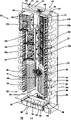
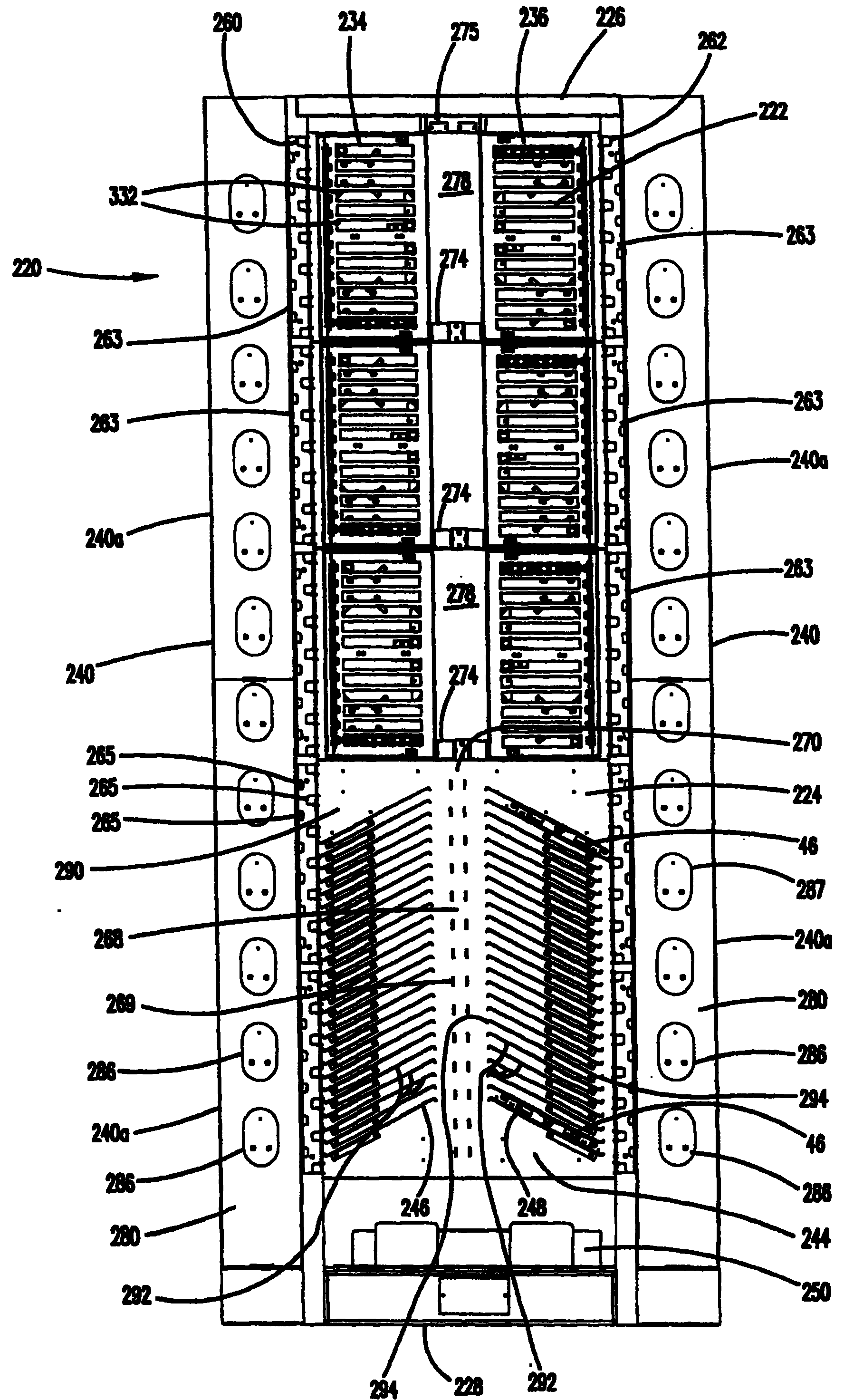
Now see also Figure 14-Figure 24, there is shown that a kind of optical cable that is used for to distributing frame inside splices, second preferred embodiment of the distributing frame 220 of termination and management.The top 222 of distributing frame 220 is formed with a termination area.The bottom 224 of distributing frame 220 is formed with a splice region.The optical cable that comprises one or more individual fibers can enter from an overhead fiber optic cable facility from top to bottom by the top 226 of distributing frame 220 usually, or from the sunken bottom plate facility of the bottom 228 that is positioned at distributing frame 220 from last and enter.If optical cable is a termination in advance, each optical cable then directly extends to termination area 222.If enter the optical cable of distributing frame 220 and be not termination in advance, each optical cable then extends splice region 224 to splice mutually with optical cable through termination.Each optical cable extends to termination area 222 from splice region 224 then.In termination area 222, be provided with a plurality of termination location that touch and use and can be used to and to be connected with terminating optical cables such as other optical cable that connects flexible cord or connect the optical cable through optical cables of termination for those.Telecommunication apparatus can pass through distributing frame 200 cross connection between each termination location.
Distributing frame 220 comprises that one can support the support 230 of a plurality of distribution frame with outside plant enclosure 232.In described preferred embodiment, be provided with the left and right row 234,236 of distribution frame with outside plant enclosure 232.Each row 234,236 in the illustrated embodiment include three independently distribution frame with outside plant enclosure 232a (left side), 232b (right side).
Support 230 also supports one along wherein row of distribution frame with outside plant enclosure 232 or the fiber optic cable management panel 240 of two row, 234,236 perpendicular positionings.In illustrated embodiment, be provided with two fiber optic cable management panels 240.Management-plane 240 links to each other with the end 231 of support 230.Additional support 230 can be installed on each management-plane 240 as required, and wherein management-plane is as the distance piece between the adjacent stent 230.
Each management-plane 240 includes two part 240a.Pointed in conjunction with distributing frame 20 as mentioned, all be installed on independent distribution frame with outside plant enclosure 232a, the 232b of support 230 and the independent sector 240a of fiber optic cable management panel 240 individually by being provided with, these modules can add to support 230 at different time, and can be changed if desired.Equally, customization distributing frame 220 can be arranged on six distribution frame with outside plant enclosure 232a, 232b of those each fiber optic cable management panels 240 that can adopt other fiber management equipment rather than illustrated embodiment in one or more zones of support 230 and the place of two part 240a.
Support 230 also supports a terminal board frame component 244 that is used for holding a plurality of joint plate rails 46.Distributing frame 220 comprises the joint plate rail keeper 246,248 of two folded vertical stackings.Can be used for distributing frame 220 in conjunction with distributing frame 20 pointed joint plate rails 46 as mentioned.Perhaps, also can adopt other joint plate rail.
Support 230 also supports a horizontal cable drum rack 250 that is positioned at splice region 224 belows.Horizontal plate rail 250 can support those connection optical cables that extends between the left and right row 234,236 on distributing frame 220 front portions, at distribution frame with outside plant enclosure 232.Plate rail 250 also can support the connection optical cable that extends between those telecommunication apparatus in distributing frame 220 and other distributing frame 220 or adjacent domain.
Support 230 also supports two optical cable guides 260,262 longitudinally, and a described optical cable guide is arranged on each side of support 230.Optical cable guide 260,262 comprises a plurality of finger pieces that separate each other 265, and the vertical side that they can make optical cable pass through each guide inserts the inside of each optical cable guide 260,262.Each optical cable guide 260,262 is preferably made several segments 263, as the parts of the brick pattern of distributing frame 220 design.
As above pointed in conjunction with distributing frame 220, the independent member that each member of formation distributing frame 220 is more preferably kept together by fastener has versatility to help assembling and to make to use.In illustrated embodiment, distribution frame with outside plant enclosure 232, fiber optic cable management panel 240, terminal board frame component 244, cable drum rack 250 and optical cable guide 260,262 separate with support 230.
Distributing frame 220 is formed with the various access ports that make optical cable enter distributing frame 220.The pit of the stomach 266 can make each optical cable enter distributing frame 220 from bottom to up from a heaving floor facility in the bottom 228, of distributing frame 220.Central passage 268 can make each optical cable pass through each independently joint plate rail 246.Being provided with some wire clamps 267 and setting fastening 269 is to be fixed on the distributing frame 220 will import optical cable securely.One central passage 270 couples together splice region 224 and termination area 222.Near the top 226 of distributing frame 220, be provided with an access port 272 and optical cable wire clamp 275.For optical cable is carried out pre-termination, can make each optical cable directly pass open top 272 to terminate in the distribution frame with outside plant enclosure 232.For the optical cable that the good optical cable of those and termination splices mutually, opening 272 leads to a vertical channel 278 and that extends downward the central passage 270 of splice region 224 and is used for the setting fastening 269 that terminating optical cables spliced at joint plate rail 246 places.Being provided with some snap rings 274 manages with the passage to the optical cable in the termination area 222.
Each fiber optic cable management panel 240 includes: a core 280 and the center spool 286 that one or morely vertically separates, extends forward from core 280.Spool 286 is to be used for depositing the unnecessary length that connects optical cable (such as the connection optical cable that extends) between the left and right row 234,236 of distribution frame with outside plant enclosure 232.Each spool 286 preferably includes before one bead 287 and optical cable is remained on the spool 286 helping.
Terminal board frame component 244 comprises: a main vertical support 290 and a plurality of partition wall 292 that extends forward.Described partition wall 292 is preferably disposed on two and vertically folds in 246,248.And described partition wall 292 preferably tilts.Terminal board frame component 244 shown in the figure is that near the optical cable that is used for entering the top 226 of distributing frame 220 with those distributing frame uses.If optical cable 228 enters from the end, making partition wall 292 may be favourable along tilting once the reverse direction shown in the modified distributing frame 520 as shown in figure 27.For the ease of joint plate rail 46 being remained on those, on two opposite side of each partition wall 292, be provided with side flange 294 by partition wall 292 formed unique spacer chamber interior.Thereby be provided with some forward recess 295 in addition and can touch a joint plate rail 46 that is stored easily.Being obliquely installed of partition wall 292 helps to reduce by the occupied horizontal space of terminal board frame component, and can provide enough big fiber channel spacing to separate with upper channel 278.
Horizontal cable drum rack 250 comprises a main horizontal part 299, a rear wall 300 and one or more antetheca 302.The connection optical cable that described front and back walls 302,299 helps those to be passed horizontal cable drum rack 250 is protected and clamping.
Now see also Figure 17-Figure 23, each distribution frame with outside plant enclosure 232 comprises: a top 310; One bottom 312; Opposite side 314,316; An and rear portion 318.Side 314 is formed with one with three sides side opening 315 that is the boundary.Side opening 315 can make optical cable insert the inside of module 232.Illustrated module 232 is to be taken from right row 236.Preferably, each distribution frame with outside plant enclosure 232a, 232b are identical, but all are positioned in the orientation of a reversing.Therefore, top 310 and bottom 312 are in an inverted orientation with respect to the left column 234 of module 232.
Each distribution frame with outside plant enclosure 232 all be formed with one preferably can with door or main panel 324 close uncovered anterior 320, described main panel hingedly is installed on main casing 322.Main panel 324 is rotatably installed near the side 316 with a hinge 328.Main panel 324 comprises that a plurality of openings 332 are (referring to Figure 14-Figure 16), the size of each opening can be held one or more breakout boxs 134.Opening 332 is configured to long and narrow slit.For the ease of the installation of breakout box 134, be provided with the retainer 336 of inclination.Just as noted above, can adopt the various breakout boxs 134 that comprise SC type breakout box.Preferably, main panel 324 comprises six upper sheds 332 and six under sheds 332, and each opening all can hold the retainer 336 and the breakout box 134 of eight inclinations.Perhaps, as pointing out among Fig. 1-embodiment illustrated in fig. 13, can independently opening be set for each breakout box.
As above pointed in conjunction with distributing frame 20, back connector 142b links to each other from the optical cable that telecommunication apparatus enters distributing frame 220 with those.The rear portion 340 of main panel 324 mainly is as the semifixed web member between connector 142b and the breakout box 134.The front portion 338 of main panel 324 is formed with a plurality of termination location that touch, and these termination location can be interconnected with one another by connecting optical cable and connector 142a, thereby can carry out cross connection to telecommunication apparatus.Main panel 324 comprises an inclined side panel 343.Side panel 343 comprises that a file is adjacent to the clip 344 of each row's breakout box 134.Clip 344 can be with main panel 324 and side panel 343 rotations.Each clip 344 can hold those and come from the optical cable that is arranged on each the connector 142a in each row of openings.Each optical cable extends through the side entrance of each optical cable guide 260,262 from each clip 344.When main panel 324 rotations, clip 344 helps clamping and each optical cable of protection.If there is not clip 344, rotatablely moving of main panel 324 just may spur or promote some part that those are positioned at the optical cable in the optical cable guide 260,262 excessively.
Main panel 324 also comprises upper and lower articulated slab 346,348.Top board 350 and base plate 352 have formed the top 310 of distribution frame with outside plant enclosure 332 and bottom 312 and have comprised an articulated slab part 354,356 separately, and described articulated slab part can be rotatably mounted in main panel 324 top board 350 and base plate 352 with articulated slab 346,348 cooperations.Each articulated slab part 354,356 includes the rotation of a retainer 358,360 with restriction main panel 324.
Main panel 324 is arranged to have angle with a vertical plane that is parallel to the front and rear of distributing frame 220.This being obliquely installed can make those its longitudinal axis increase transverse to the density of breakout box 134 tops of forward and backward plane setting.Equally, the management of optical cable can be with making optical cable towards 260,262 inclinations of optical cable guide and the convenience that becomes.For the right row 236 of module 232, main panel 324 tilts towards the opposite side of support 230.Similarly, for the left column 234 of module 232, main panel 324 is towards the left side of support 230.The use of inclination retainer 362 can make each optical cable recede towards the right side, the left side of support 230.The retainer 362 that tilts clamps each breakout box 134, and therefore, its longitudinal axis is divided into a non-horizontal angle with respect to the planar portions of main panel 324.The U.S. Patent No. of owning together 5,214,735 illustrates several retainer examples that can adopt main panel 324 of knowing clearly.This paper quotes U.S. Patent No. 5,214,735 contents that disclosed usefulness as a reference.
For main panel 324 is maintained in its closed position, be provided with two with the similar breech lock 362 of the breech lock above mentioned 162.Each breech lock 362 all is meshed with a protruding tongue 364 that extends out from top board 350, base plate 352.
Now see also Figure 20-Figure 23, be provided with some interior cables characteristics of management things in distribution frame with outside plant enclosure 232 inside.Some optical fibre clips 382 clamp one or some by the optical cable that side 314 enters distribution frame with outside plant enclosure 232 securely at side opening 315 places.Drop wire clip 382a is used for those optical cables that enters distribution frame with outside plant enclosure 232 from top to bottom.Last wire clamp 382b is used for the optical cable that those enter distribution frame with outside plant enclosure 232 from bottom to top.Preferably, all wire clamps 382 are all located with an angle.Wire clamp 382 preferably is positioned to be installed on the bead 383.Each individual fibers is passed the various optical cable guides 386 that comprise protruding tongue, spool, clip or snap ring and is determined route from wire clamp 382.One setting fastening carriage 390 can be used with wire clamp 382, perhaps substitute wire clamp 382, hitch with the optical cable bolt that will enter distribution frame with outside plant enclosure 332.On the rear portion 340 of main panel 324, a back plate rail 392 is positioned at the center on the main panel 324, and level protrudes out backward.Back plate rail 392 comprises the optical cable snap ring 394 of one or more levels.One vertical flanges 395 extends back with protection optical cable and connector from the free edge of main panel 324.
As shown in figure 21, several representational optical cables (optical fiber) enter distribution frame with outside plant enclosure 232 by side opening 315.Wire clamp 382 clamps the representational first and second optical fiber 384a, 384b.The first optical fiber 384a walks around lower winding shaft or guide 386a extends to a upper winding shaft or guide 386b, walks around turning guide 386c then and extend to snap ring 388b, passes horizontal snap ring 394 and extends to one of them upper/lower positions on the main panel 324.Oneself extends to down turning guide 386d by following guide 386a the second representative optical fiber 384b, passes down snap ring 388a then.Oneself following snap ring 388a of the second optical fiber 384b passes horizontal snap ring 394 and extends to position on one on the main panel 324.
The use-pattern of the use-pattern of distributing frame 220 and distributing frame 20 is similar, and wherein, those enter the optical cable that the optical cable of buildings and those link to each other with various telecommunication apparatus in the buildings can to utilize left and right row 234,236 to come termination.Distributing frame 220 can be used for connecting and respectively connect optical cable, with each back termination location of cross connection.Each connects optical cable and passes through from splice region 224 belows.Connection optical cable link position before each enters and is used for to connecting one of them optical cable guide 260,262 that optical cable carries out vertical management.Each optical cable is flatly walked to the opposite side of distributing frame 220 from the lower end of optical cable guide 260,262, perhaps walks to another distributing frame or miscellaneous equipment.The unnecessary length that connects optical cable can be wound on the suitable spool 286 in one of them fiber optic cable management panel 240, thereby can easily these unnecessary length be deposited, and can avoid connecting the optical cable mat thus.Perhaps, connecting optical cable can walk to a contiguous distributing frame or a miscellaneous equipment from left column 234 or from right row 236.
Now see also Figure 25 and Figure 26, there is shown a kind of distributing frame 420, this distributing frame is because feature such as support 230, distribution frame with outside plant enclosure 232, terminal board frame component 244, fiber optic cable management panel 240 and guide 260,262 and distributing frame 220 are similar.Distributing frame 420 comprises and is positioned at termination area 222, adjustable optical cable snap ring 474.Snap ring 474 comprises outer arm 475 and movable inner arm 476.The position of inner arm 476 and spacing can be according to treating that position and quantity by the optical cable of snap ring 474 clampings selectes.For example, at first extend to optical cable splice region 244, that enter from the top for those, and those extend upwardly to other optical cable of distribution frame with outside plant enclosure 232 from splice region 244, independent space is useful.Inner arm 476 is fixed on the connecting portion 478 of outer arm 475 by fastener 477.Inner arm 476 is formed with an inner cavity chamber 480 that is used to enter each optical cable of distributing frame 420.Can adopt some serrations 482 to fix O shape circle or other setting fastening so that each optical cable is fixed in the chamber 480.Other optical cable extends to the optical cable of termination area 224 such as those from splice region 244, can be positioned at outside the chamber 480, in the zone 484.Equally, distributing frame 420 also comprises a under shed 480, thereby can make optical cable pass the rear side of distributing frame 420, so that make described optical cable walk second distributing frame of installing back-to-back with distributing frame 420 to, or links to each other with other telecommunication apparatus.
As mentioned above distributing frame 520 shown in Figure 27 comprises terminal board frame component 244 like that, and this assembly is installed in a upside down position, and therefore, each separator 292 is along an inclination that is directed downwards towards distributing frame 520 centers.Those 528 enter and the optical cable that gives termination at terminal board frame component 244 places is useful from the bottom for management in the plan of establishment shown in Figure 27.In order to increase the efficient of manufacturing, assembly 244 and distributing frame the 420, the 520th, identical, but it is installed selectively with required orientation.
Now see also Figure 30-Figure 37, there is shown that the optical cable that is used for to distributing frame inside splices, the 4th preferred embodiment 620 of the distributing frame of termination and management.The top 622 of distributing frame 620 is formed with a termination area.The bottom 624 of distributing frame 620 is formed with a splice region, for example as mentioned in conjunction with described in each embodiment of Fig. 1-shown in Figure 29 like that.The optical cable that comprises one or more individual fibers can enter from an overhead fiber optic cable facility from top to bottom by the top 626 of distributing frame 620 usually, or enters from bottom to top from the sunken bottom plate facility of the bottom 628 that is positioned at distributing frame 620.If optical cable is a termination in advance, each optical cable then directly extends to termination area 622.If enter the optical cable of distributing frame 620 and be not termination in advance, then each optical cable extends to splice region 624 to splice mutually with optical cable through termination.
Distributing frame 620 comprises that one can support the support 630 of a plurality of distribution frame with outside plant enclosure 632.Shown in preferred embodiment in, be provided with the left and right row of distribution frame with outside plant enclosure 632.In Figure 30-Figure 32, only show right row 636.Each row in the illustrated embodiment include three independently distribution frame with outside plant enclosure 632b (only showing two distribution frame with outside plant enclosure among the figure).
Distributing frame 620 can be used to by coming the cross connection telecommunication apparatus by the termination location that distributing frame provided.Distributing frame 620 comprises that also a fiber optic cable management panel (not shown) and as indicated above is positioned at the horizontal cable drum rack 650 of splice region 624 belows.
Support 630 also supports two vertical optical cable guides 660,662, and a described optical cable guide is arranged on each side of support 630, so that the connection optical cable that is adjacent to distributing frame 620 front portions is being managed and protected.Optical cable guide 660,662 comprises a plurality of finger pieces 664, and described finger piece comprises the finger piece 665 of an inclination.Each optical cable guide 660,662 is preferably made several segments 663, as the parts of the brick pattern of distributing frame 620 design.Each segment 663 includes a base portion 670, a sidepiece 672 and and is used for the Qianmen (not shown) hingedly is installed on the hinge 674 of support 630.Finger piece 664,665 all extends out from sidepiece 672.
As above pointed in conjunction with distributing frame 20,220, the independent member that each member of formation distributing frame 620 is more preferably kept together by fastener has versatility to help assembling and to make to use.In illustrated embodiment, distribution frame with outside plant enclosure 632, terminal board frame component and optical cable guide 660,662 separate with support 630.
Now see also Figure 33-Figure 36, each distribution frame with outside plant enclosure 632 includes: a top 710; One bottom 712; Opposite side 714,716; An and rear portion 718.Side 714 is formed with one with three sides side opening 715 that is the boundary.Side opening 715 can make optical cable insert the inside of module 632.Figure 33-module 732 shown in Figure 37 is to be taken from right row 636.Opposite with the distribution frame with outside plant enclosure 232a, the 232b that above point out, employed each distribution frame with outside plant enclosure is different in the distribution frame with outside plant enclosure 632 that comes from right row 636 and the left column, and this will can see hereinafter.
Each distribution frame with outside plant enclosure 632 all be formed with one preferably can with door or main panel 724 close uncovered anterior 720, described main panel hingedly is installed on main casing 722 in a kind of with above pointed module 232 similar modes.Main panel 724 is constructed in the pointed main panel 324 similar modes of a kind of and the installation that above combines breakout box 134.Main panel 724 shown in the figure has been filled breakout box 134.
In conjunction with the substituting of the pointed clip 344 of main panel 324, main panel 724 comprises a plurality of guides or extension 744, near each row's breakout box 134 guide or extension is arranged as above.Guide 744 plate 743 from the side extends out.Guide 744 is with main panel 724 and side panel 743 rotations.Each guide 744 all can clamp and come from the optical cable that is arranged on each the connector 142a in each row of openings.Each optical cable extends through the side joint inlet of nearest vertical optical cable guide 660,662 from guide 744.Guide 744 helps clamping and each optical cable of protection when main panel 724 rotations.If there is not guide 744, rotatablely moving of main panel 124 just may spur or promote some part that those are positioned at the optical cable in the optical cable guide 660,662 excessively.
Guide 744 preferably is made for the extension of plane side panel 743.Sheet metal is the conventional material that is used for making main panel 724 and side panel 743 and guide 744.Each guide 744 includes one and has a main extension 746 that tilts protruding tongue 748, and described protruding tongue tilts towards the direction of separately vertical optical cable guide 660,662.Vertically extending on the both sides of protruding tongue 748 is first and second finger pieces 750,752.One slit 754 is formed on a finger piece 750,752 and of a guide 744 between the opposed finger piece 752,750 of the adjacent guide 744 above or below the corresponding guide.The size of slit 754 can be held each optical cable in such as the installation of optical cable or demolishing process.Preferably, slit 754 forms an angle with horizontal direction, thereby helps to prevent in the process that other optical cable moves or in the process that main panel 724 moves that each optical cable from dropping out from guide 744.One edge guard member 756 card fits over the top of main extension 746, and the damage that may cause each optical cable with the sharp edges that prevents main extension 746 is if this can occur in such as in the situation that adopts sheet metal.
Be similar to above pointed main panel 324, main panel 724 hingedly is installed on the top 710 and the bottom 712 of distribution frame with outside plant enclosure 632.And main panel 724 forms an angle with respect to the vertical plane that a front and rear that is parallel to distributing frame 620 extends.And main panel 724 comprises the inclination keeper 362 that employing is as indicated above.For main panel 724 is maintained in its closed position, be provided with two with the breech lock of the horizontal operation of above pointing out breech lock 762 similar, vertical work.
Now see also Figure 34 and Figure 35, be provided with some interior cables characteristics of management things in distribution frame with outside plant enclosure 632 inside.Some optical fibre clips 782 clamp one or some by the optical cable that side 714 enters distribution frame with outside plant enclosure 632 securely at side opening 715 places.Drop wire clip 782a is used for those optical cables that enters distribution frame with outside plant enclosure 632 from bottom to top.Last wire clamp 782b is used for the optical cable that those enter distribution frame with outside plant enclosure 632 from top to bottom.Preferably, all wire clamps 782 are all located with an angle.Wire clamp 782 preferably is positioned to be installed on the bead 783.Each individual fibers is passed the various optical cable guides 786 that comprise protruding tongue, spool, clip or snap ring and is determined route from wire clamp 782.One setting fastening carriage can be used with wire clamp, perhaps substitute wire clamp, hitch with the optical cable bolt that will enter distribution frame with outside plant enclosure 632.On the rear portion 340 of main panel 724, a back plate rail 392 is positioned at the center on the main panel 724, and level protrudes out backward.Back plate rail 792 comprises the optical cable snap ring 794 of one or more levels.One vertical flanges 795 extends back with protection optical cable and connector from the free edge of main panel 724.
As shown in figure 35, several representational optical cables (optical fiber) enter distribution frame with outside plant enclosure 632 by side opening 715.Wire clamp 782 clamps the representational first and second optical fiber 784a, 784b.The first optical fiber 784a walks around lower winding shaft or guide 786a extends to a upper winding shaft or guide 786b, passes snap ring 786c then, passes horizontal snap ring 74 and extend to one of them link position on the main panel 724.
Now see also Figure 37, be provided with a back cover cap 800, be positioned near each link position on main panel 724 rear sides optical cable to protect those.In Figure 37, show the distribution frame with outside plant enclosure 632 of the left column that comes from distributing frame 620.Module 632 shown in Figure 37 is mirror images of module 632 shown in Figure 34.Cover cap 800 is installed on back plate rail 792 by a protruding tongue 802 that is positioned on the flange 796 of plate rail 792.One leaf spring 804 is installed in the groove 798.Two protruding tongues 806,808 in top are meshed with the top of main panel 724, with further fixedly cover cap 800.
The manufacturing and the use of each member of the present invention have been described above explanation, each example and data integrity.Because can make the embodiment that does not much deviate from the present invention's spirit and protection domain to the present invention, therefore, the present invention is limited by appending claims.