CN1311153C - EGR-gas temp estimation appts. for I.C. engine - Google Patents
EGR-gas temp estimation appts. for I.C. engine Download PDFInfo
- Publication number
- CN1311153C CN1311153C CNB2003101045529A CN200310104552A CN1311153C CN 1311153 C CN1311153 C CN 1311153C CN B2003101045529 A CNB2003101045529 A CN B2003101045529A CN 200310104552 A CN200310104552 A CN 200310104552A CN 1311153 C CN1311153 C CN 1311153C
- Authority
- CN
- China
- Prior art keywords
- egr
- egr gas
- gas
- temperature
- gas temperature
- Prior art date
- Legal status (The legal status is an assumption and is not a legal conclusion. Google has not performed a legal analysis and makes no representation as to the accuracy of the status listed.)
- Expired - Fee Related
Links
- 238000002485 combustion reaction Methods 0.000 claims abstract description 83
- 238000001816 cooling Methods 0.000 claims abstract description 67
- 239000002826 coolant Substances 0.000 claims abstract description 15
- 239000007789 gas Substances 0.000 claims description 467
- 239000002912 waste gas Substances 0.000 claims description 150
- 238000010791 quenching Methods 0.000 claims description 69
- 230000008859 change Effects 0.000 claims description 6
- 239000000659 freezing mixture Substances 0.000 claims description 3
- 239000000498 cooling water Substances 0.000 abstract description 14
- 239000003570 air Substances 0.000 description 95
- 238000002347 injection Methods 0.000 description 62
- 239000007924 injection Substances 0.000 description 62
- 239000000446 fuel Substances 0.000 description 53
- 238000010586 diagram Methods 0.000 description 45
- 238000000034 method Methods 0.000 description 26
- 230000008569 process Effects 0.000 description 13
- QVGXLLKOCUKJST-UHFFFAOYSA-N atomic oxygen Chemical compound [O] QVGXLLKOCUKJST-UHFFFAOYSA-N 0.000 description 10
- 239000001301 oxygen Substances 0.000 description 10
- 229910052760 oxygen Inorganic materials 0.000 description 10
- 238000012937 correction Methods 0.000 description 8
- 238000002474 experimental method Methods 0.000 description 6
- 239000000295 fuel oil Substances 0.000 description 6
- 238000007599 discharging Methods 0.000 description 5
- 238000005259 measurement Methods 0.000 description 5
- 238000011144 upstream manufacturing Methods 0.000 description 5
- 238000010304 firing Methods 0.000 description 4
- 238000012546 transfer Methods 0.000 description 4
- PNEYBMLMFCGWSK-UHFFFAOYSA-N Alumina Chemical compound [O-2].[O-2].[O-2].[Al+3].[Al+3] PNEYBMLMFCGWSK-UHFFFAOYSA-N 0.000 description 3
- 101100448223 Caenorhabditis elegans gcy-1 gene Proteins 0.000 description 3
- MWUXSHHQAYIFBG-UHFFFAOYSA-N Nitric oxide Chemical compound O=[N] MWUXSHHQAYIFBG-UHFFFAOYSA-N 0.000 description 3
- 239000002585 base Substances 0.000 description 3
- 238000013507 mapping Methods 0.000 description 3
- 239000000203 mixture Substances 0.000 description 3
- 230000004044 response Effects 0.000 description 3
- 239000011575 calcium Substances 0.000 description 2
- 239000000110 cooling liquid Substances 0.000 description 2
- 229910052751 metal Inorganic materials 0.000 description 2
- 239000013618 particulate matter Substances 0.000 description 2
- BASFCYQUMIYNBI-UHFFFAOYSA-N platinum Chemical compound [Pt] BASFCYQUMIYNBI-UHFFFAOYSA-N 0.000 description 2
- 239000011734 sodium Substances 0.000 description 2
- OYPRJOBELJOOCE-UHFFFAOYSA-N Calcium Chemical compound [Ca] OYPRJOBELJOOCE-UHFFFAOYSA-N 0.000 description 1
- DGAQECJNVWCQMB-PUAWFVPOSA-M Ilexoside XXIX Chemical compound C[C@@H]1CC[C@@]2(CC[C@@]3(C(=CC[C@H]4[C@]3(CC[C@@H]5[C@@]4(CC[C@@H](C5(C)C)OS(=O)(=O)[O-])C)C)[C@@H]2[C@]1(C)O)C)C(=O)O[C@H]6[C@@H]([C@H]([C@@H]([C@H](O6)CO)O)O)O.[Na+] DGAQECJNVWCQMB-PUAWFVPOSA-M 0.000 description 1
- WHXSMMKQMYFTQS-UHFFFAOYSA-N Lithium Chemical compound [Li] WHXSMMKQMYFTQS-UHFFFAOYSA-N 0.000 description 1
- ZLMJMSJWJFRBEC-UHFFFAOYSA-N Potassium Chemical compound [K] ZLMJMSJWJFRBEC-UHFFFAOYSA-N 0.000 description 1
- 238000010521 absorption reaction Methods 0.000 description 1
- 229910052783 alkali metal Inorganic materials 0.000 description 1
- 150000001340 alkali metals Chemical class 0.000 description 1
- 229910052784 alkaline earth metal Inorganic materials 0.000 description 1
- 150000001342 alkaline earth metals Chemical class 0.000 description 1
- 239000012080 ambient air Substances 0.000 description 1
- 229910052788 barium Inorganic materials 0.000 description 1
- DSAJWYNOEDNPEQ-UHFFFAOYSA-N barium atom Chemical compound [Ba] DSAJWYNOEDNPEQ-UHFFFAOYSA-N 0.000 description 1
- 230000005540 biological transmission Effects 0.000 description 1
- 229910052792 caesium Inorganic materials 0.000 description 1
- TVFDJXOCXUVLDH-UHFFFAOYSA-N caesium atom Chemical compound [Cs] TVFDJXOCXUVLDH-UHFFFAOYSA-N 0.000 description 1
- 229910052791 calcium Inorganic materials 0.000 description 1
- 239000003054 catalyst Substances 0.000 description 1
- 239000000567 combustion gas Substances 0.000 description 1
- 238000010276 construction Methods 0.000 description 1
- 230000008878 coupling Effects 0.000 description 1
- 238000010168 coupling process Methods 0.000 description 1
- 238000005859 coupling reaction Methods 0.000 description 1
- 239000003500 flue dust Substances 0.000 description 1
- 239000002828 fuel tank Substances 0.000 description 1
- 229910052746 lanthanum Inorganic materials 0.000 description 1
- FZLIPJUXYLNCLC-UHFFFAOYSA-N lanthanum atom Chemical compound [La] FZLIPJUXYLNCLC-UHFFFAOYSA-N 0.000 description 1
- 229910052744 lithium Inorganic materials 0.000 description 1
- 239000002184 metal Substances 0.000 description 1
- 238000012986 modification Methods 0.000 description 1
- 230000004048 modification Effects 0.000 description 1
- 239000003921 oil Substances 0.000 description 1
- 239000005022 packaging material Substances 0.000 description 1
- 230000032696 parturition Effects 0.000 description 1
- 229910052697 platinum Inorganic materials 0.000 description 1
- 239000011148 porous material Substances 0.000 description 1
- 229910052700 potassium Inorganic materials 0.000 description 1
- 239000011591 potassium Substances 0.000 description 1
- 229910052761 rare earth metal Inorganic materials 0.000 description 1
- 150000002910 rare earth metals Chemical class 0.000 description 1
- 229910052708 sodium Inorganic materials 0.000 description 1
- 239000007921 spray Substances 0.000 description 1
- 230000002123 temporal effect Effects 0.000 description 1
- 238000012360 testing method Methods 0.000 description 1
- 229910052727 yttrium Inorganic materials 0.000 description 1
- VWQVUPCCIRVNHF-UHFFFAOYSA-N yttrium atom Chemical compound [Y] VWQVUPCCIRVNHF-UHFFFAOYSA-N 0.000 description 1
Images


Classifications
-
- F—MECHANICAL ENGINEERING; LIGHTING; HEATING; WEAPONS; BLASTING
- F02—COMBUSTION ENGINES; HOT-GAS OR COMBUSTION-PRODUCT ENGINE PLANTS
- F02D—CONTROLLING COMBUSTION ENGINES
- F02D41/00—Electrical control of supply of combustible mixture or its constituents
- F02D41/02—Circuit arrangements for generating control signals
- F02D41/14—Introducing closed-loop corrections
- F02D41/1438—Introducing closed-loop corrections using means for determining characteristics of the combustion gases; Sensors therefor
- F02D41/1444—Introducing closed-loop corrections using means for determining characteristics of the combustion gases; Sensors therefor characterised by the characteristics of the combustion gases
- F02D41/1448—Introducing closed-loop corrections using means for determining characteristics of the combustion gases; Sensors therefor characterised by the characteristics of the combustion gases the characteristics being an exhaust gas pressure
- F02D41/145—Introducing closed-loop corrections using means for determining characteristics of the combustion gases; Sensors therefor characterised by the characteristics of the combustion gases the characteristics being an exhaust gas pressure with determination means using an estimation
-
- F—MECHANICAL ENGINEERING; LIGHTING; HEATING; WEAPONS; BLASTING
- F02—COMBUSTION ENGINES; HOT-GAS OR COMBUSTION-PRODUCT ENGINE PLANTS
- F02D—CONTROLLING COMBUSTION ENGINES
- F02D41/00—Electrical control of supply of combustible mixture or its constituents
- F02D41/0025—Controlling engines characterised by use of non-liquid fuels, pluralities of fuels, or non-fuel substances added to the combustible mixtures
- F02D41/0047—Controlling exhaust gas recirculation [EGR]
- F02D41/0065—Specific aspects of external EGR control
- F02D41/0072—Estimating, calculating or determining the EGR rate, amount or flow
-
- F—MECHANICAL ENGINEERING; LIGHTING; HEATING; WEAPONS; BLASTING
- F02—COMBUSTION ENGINES; HOT-GAS OR COMBUSTION-PRODUCT ENGINE PLANTS
- F02M—SUPPLYING COMBUSTION ENGINES IN GENERAL WITH COMBUSTIBLE MIXTURES OR CONSTITUENTS THEREOF
- F02M26/00—Engine-pertinent apparatus for adding exhaust gases to combustion-air, main fuel or fuel-air mixture, e.g. by exhaust gas recirculation [EGR] systems
- F02M26/13—Arrangement or layout of EGR passages, e.g. in relation to specific engine parts or for incorporation of accessories
- F02M26/22—Arrangement or layout of EGR passages, e.g. in relation to specific engine parts or for incorporation of accessories with coolers in the recirculation passage
- F02M26/23—Layout, e.g. schematics
- F02M26/28—Layout, e.g. schematics with liquid-cooled heat exchangers
-
- F—MECHANICAL ENGINEERING; LIGHTING; HEATING; WEAPONS; BLASTING
- F02—COMBUSTION ENGINES; HOT-GAS OR COMBUSTION-PRODUCT ENGINE PLANTS
- F02D—CONTROLLING COMBUSTION ENGINES
- F02D41/00—Electrical control of supply of combustible mixture or its constituents
- F02D41/0025—Controlling engines characterised by use of non-liquid fuels, pluralities of fuels, or non-fuel substances added to the combustible mixtures
- F02D41/0047—Controlling exhaust gas recirculation [EGR]
- F02D41/0065—Specific aspects of external EGR control
- F02D2041/0067—Determining the EGR temperature
- F02D2041/007—Determining the EGR temperature by estimation
-
- F—MECHANICAL ENGINEERING; LIGHTING; HEATING; WEAPONS; BLASTING
- F02—COMBUSTION ENGINES; HOT-GAS OR COMBUSTION-PRODUCT ENGINE PLANTS
- F02D—CONTROLLING COMBUSTION ENGINES
- F02D41/00—Electrical control of supply of combustible mixture or its constituents
- F02D41/30—Controlling fuel injection
- F02D41/38—Controlling fuel injection of the high pressure type
- F02D41/40—Controlling fuel injection of the high pressure type with means for controlling injection timing or duration
- F02D41/401—Controlling injection timing
-
- F—MECHANICAL ENGINEERING; LIGHTING; HEATING; WEAPONS; BLASTING
- F02—COMBUSTION ENGINES; HOT-GAS OR COMBUSTION-PRODUCT ENGINE PLANTS
- F02M—SUPPLYING COMBUSTION ENGINES IN GENERAL WITH COMBUSTIBLE MIXTURES OR CONSTITUENTS THEREOF
- F02M26/00—Engine-pertinent apparatus for adding exhaust gases to combustion-air, main fuel or fuel-air mixture, e.g. by exhaust gas recirculation [EGR] systems
- F02M26/02—EGR systems specially adapted for supercharged engines
- F02M26/04—EGR systems specially adapted for supercharged engines with a single turbocharger
- F02M26/05—High pressure loops, i.e. wherein recirculated exhaust gas is taken out from the exhaust system upstream of the turbine and reintroduced into the intake system downstream of the compressor
-
- F—MECHANICAL ENGINEERING; LIGHTING; HEATING; WEAPONS; BLASTING
- F02—COMBUSTION ENGINES; HOT-GAS OR COMBUSTION-PRODUCT ENGINE PLANTS
- F02M—SUPPLYING COMBUSTION ENGINES IN GENERAL WITH COMBUSTIBLE MIXTURES OR CONSTITUENTS THEREOF
- F02M26/00—Engine-pertinent apparatus for adding exhaust gases to combustion-air, main fuel or fuel-air mixture, e.g. by exhaust gas recirculation [EGR] systems
- F02M26/13—Arrangement or layout of EGR passages, e.g. in relation to specific engine parts or for incorporation of accessories
- F02M26/22—Arrangement or layout of EGR passages, e.g. in relation to specific engine parts or for incorporation of accessories with coolers in the recirculation passage
- F02M26/33—Arrangement or layout of EGR passages, e.g. in relation to specific engine parts or for incorporation of accessories with coolers in the recirculation passage controlling the temperature of the recirculated gases
-
- Y—GENERAL TAGGING OF NEW TECHNOLOGICAL DEVELOPMENTS; GENERAL TAGGING OF CROSS-SECTIONAL TECHNOLOGIES SPANNING OVER SEVERAL SECTIONS OF THE IPC; TECHNICAL SUBJECTS COVERED BY FORMER USPC CROSS-REFERENCE ART COLLECTIONS [XRACs] AND DIGESTS
- Y02—TECHNOLOGIES OR APPLICATIONS FOR MITIGATION OR ADAPTATION AGAINST CLIMATE CHANGE
- Y02T—CLIMATE CHANGE MITIGATION TECHNOLOGIES RELATED TO TRANSPORTATION
- Y02T10/00—Road transport of goods or passengers
- Y02T10/10—Internal combustion engine [ICE] based vehicles
- Y02T10/40—Engine management systems
Abstract
An EGR-gas temperature estimation apparatus for an internal combustion engine which has an exhaust circulation pipe and an EGR-gas cooling apparatus. The estimation apparatus obtains the cooling efficiency etaegr of the EGR-gas cooling apparatus from the temperature Tex of EGR gas at the inlet of the exhaust circulation pipe and the flow rate Gegr of the EGR gas, and obtains the temperature THW of engine cooling water, used as a coolant for the EGR-gas cooling apparatus. Subsequently, the estimation apparatus calculates the temperature Tegr of the EGR gas at the outlet of the exhaust circulation pipe by the expression Tegr=Tex-etaegr.(Tex-THW). Since the cooling efficiency etaegr greatly changes depending on the EGR-gas flow rate Gegr and the EGR-gas temperature Tex, the estimation apparatus can accurately estimate the cooling efficiency etaegr, and therefore can accurately estimate the EGR-gas temperature Tegr.
Description
Technical field
The present invention relates to a kind of internal-combustion engine EGR (exhaust gas recirculation) gas temperature estimating device, this device is inferred the temperature of the EGR gas of the waste gas circulation pipe that flows through internal-combustion engine.
Background technique
Usually, extensive known a kind of EGR device, this device make a part of waste gas circulation of internal-combustion engine to gas-entered passageway via the waste gas circulation pipe, so that reduce the nitrogen oxide (NO that discharges from internal-combustion engine
x) amount.This EGR device is applied to spark-ignited internal combustion engine and diesel engine.
Simultaneously, in diesel engine, under extremely rare air fuel ratio, realize burning.Particularly, because the needed oxygen that burns is very sufficient, so amount of fuel is largely depended in the output of diesel engine.Therefore, in diesel engine, when being recycled to reduce NO greatly
xExhaust gas discharged amount (that is mass velocity of ERG gas; Hereinafter simply be called " EGR flow rate of gas ") to such an extent as to increase and sufficient amount of fuel supplies to internal-combustion engine when having guaranteed desired internal-combustion engine output, the EGR flow rate of gas that is increased has reduced the amount of fresh air (amount of oxygen) that internal-combustion engine sucks, and amount of fresh air is converted to rich oil one side with the ratio (being air fuel ratio) of amount of fuel thus.As a result, the discharging of particulate matter (hereinafter referred to as " PS ") increases.
In view of the foregoing, developed a kind of EGR device, the EGR gas quench system (cooler for recycled exhaust gas) that wherein is used for cooling off EGR gas places the waste gas circulation pipe so that reduce the temperature of EGR gas, thereby increases the density of EGR gas.The EGR device can increase the EGR gas flow and not reduce amount of fresh air, thereby has reduced NO simultaneously
xDischarging with PM.
Simultaneously, for example, if lead the above-mentioned EGR flow rate of gas of (ER EGR Rate) control according to EGR, this EGR leads the ratio of the flow rate that is EGR flow rate of gas and all gas (hereinafter being also referred to as " air inlet ") of sucking internal-combustion engines, then EGR leads and must accurately be inferred, and lead in order accurately to infer EGR, must accurately infer air inflow.Because the temperature (intake temperature) that air inflow is surveyed according to the attachment portion between intake manifold and the cylinder (outlet of intake manifold) changes, so intake temperature must accurately be inferred.In addition, in order accurately to infer intake temperature, must accurately infer the temperature of fresh air and just with EGR gas temperature (afterwards a temperature is substantially equal to the EGR gas temperature in the outlet measurement of EGR gas quench system) before fresh air mixes.In other words, accurately determine or infer by the cooled EGR gas temperature of EGR gas quench system extremely important for the suitable control of internal-combustion engine.
In view of the foregoing, the traditional EGR device that is equipped with above-mentioned EGR gas quench system obtains value k corresponding to EGR gas quench system efficient (cooling effectiveness) according to internal-combustion engine rotational speed and fuel injection amount, and obtains its correction factor kh according to the EGR flow rate of gas.Then, conventional apparatus is with area A, EGR gas flow speed G, the specific heat Cp of EGR gas, temperature T wg, exhaust gas temperature Tex and the representation Tegr=Tex-TwgkA/ (kkhA/2-GCp) of EGR gas cooling water of the heat-transfer surface of above-mentioned value k, above-mentioned correction factor kh, EGR gas quench system, the EGR gas temperature Tegr that infers in the outlet of EGR gas quench system (for example, referring to Japanese Unexamined Patent Publication No 11-166452 (the 6th page, Figure 11 and Figure 14)).
Yet, even when flowing into the EGR gas flow constant rate of EGR gas quench system, the cooling effectiveness of EGR gas quench system (heat conductivity and heat transfer ratio) η egr alters a great deal with the temperature (this temperature is substantially equal to the EGR temperature that waste gas circulation tube inlet place is measured, and the waste gas circulation pipe links to each other with the exhaust passage at waste gas circulation tube inlet place) of the EGR gas that flows into the EGR gas quench system.Particularly, as shown in figure 17, even when the EGR gas flow constant rate that flows into the EGR gas quench system, when the temperature of the EGR gas that flows into the EGR gas quench system from first temperature variation when being higher than second temperature of first temperature, cooling effectiveness η egr also can change to the B point value from the A point value.This phenomenon can take place, and is that the heat of being drawn from EGR gas by the EGR gas quench system is just many more because the difference between the coolant temperature of the temperature of the EGR gas of inflow EGR gas quench system and EGR gas quench system is big more.
Thereby, do not consider to flow into the EGR gas quench system EGR gas temperature and the problem of above-mentioned conventional art of inferring the cooling effectiveness of EGR gas quench system is accurately to infer the EGR gas temperature in EGR gas quench system outlet port.
Summary of the invention
In view of foregoing description, an object of the present invention is to provide a kind of internal-combustion engine EGR gas temperature estimating device, this device can accurately be inferred the EGR gas temperature of EGR gas quench system outlet side by determine the cooling effectiveness of EGR gas quench system according to the EGR gas temperature of the inlet side of EGR gas quench system.
Another object of the present invention provides a kind of internal-combustion engine EGR gas temperature estimating device, this device can be by determining the cooling effectiveness of EGR gas quench system according to the EGR gas temperature at waste gas circulation tube inlet place, accurately infer the gas temperature at the EGR of EGR gas outlet, this EGR gas outlet is the attachment portion between waste gas circulation pipe and the gas-entered passageway.
The invention provides a kind of internal-combustion engine EGR gas temperature estimating device, this internal-combustion engine has one and is connected the waste gas circulation pipe between exhaust passage and the gas-entered passageway, an EGR control valve and an EGR gas quench system that places the waste gas circulation pipe that places this waste gas circulation pipe and be suitable for controlling the EGR flow rate of gas that flows into the waste gas circulation pipe.This EGR gas temperature estimating device comprises the device of the EGR gas temperature that is used to obtain EGR gas quench system inlet side; Be used to obtain device corresponding to the analog value of the EGR gas flow speed of the waste gas circulation pipe of flowing through; Cooling effectiveness obtains device, and the value by the analog value that is obtained obtains divided by the EGR gas temperature of the EGR gas quench system inlet side that is obtained obtains cooling effectiveness; Outlet EGR gas temperature estimating device with the EGR gas temperature that is used for inferring EGR gas quench system outlet side according to the EGR gas temperature and the acquired cooling effectiveness of EGR gas quench system inlet side.
As mentioned above, in this device, because the cooling effectiveness of EGR gas quench system determines according to the EGR gas temperature of EGR gas quench system inlet side, so determined cooling effectiveness is near actual value.Therefore, this device can accurately be inferred the temperature of the EGR gas of EGR gas quench system outlet side.
The present invention also provides a kind of internal-combustion engine EGR gas temperature estimating device, this internal-combustion engine has one and is connected waste gas circulation pipe between exhaust passage and the gas-entered passageway, an EGR control valve that places this waste gas circulation pipe and be suitable for controlling the EGR gas flow speed that flows into the waste gas circulation pipe, and the EGR gas quench system between attachment portion that places the waste gas circulation pipe is connected to the exhaust passage at EGR control valve and waste gas circulation pipe waste gas circulation pipe.This EGR gas temperature estimating device comprises that inlet EGR gas temperature obtains device, the EGR gas temperature that is used to obtain place, EGR gas access is as waste gas circulation tube inlet EGR gas temperature, and this EGR gas access is the attachment portion that the waste gas circulation pipe is connected to the waste gas circulation pipe of exhaust passage; The analog value of EGR flow rate of gas obtains device, is used to obtain the analog value corresponding to the EGR flow rate of gas of the EGR gas flow speed of the waste gas circulation pipe of flowing through; Cooling effectiveness obtains device, is used for the value that obtains divided by the waste gas circulation tube inlet EGR gas temperature that is obtained according to the analog value by the EGR flow rate of gas that is obtained, obtains the cooling effectiveness of EGR gas quench system; With outlet EGR gas temperature estimating device, be used for according to the waste gas circulation tube inlet EGR gas temperature and the acquired cooling effectiveness that are obtained, the EGR gas temperature of inferring the EGR gas outlet is as waste gas circulation pipe outlet EGR gas temperature, and this EGR gas outlet is the attachment portion of the waste gas circulation pipe that links to each other with gas-entered passageway of waste gas circulation pipe.
In EGR gas temperature estimating device of the present invention, obtain EGR gas temperature that device obtains the EGR gas access as waste gas circulation tube inlet EGR gas temperature by inlet EGR gas temperature, this EGR gas access is the attachment portion that the waste gas circulation pipe is connected to the waste gas circulation pipe of exhaust passage.It can be the device that obtains waste gas circulation tube inlet EGR gas temperature by the calculating of fresh air flow rate, amount of fuel, suction pressure, exhaust pressure etc. that inlet EGR gas temperature obtains device, or obtaining the device of waste gas circulation tube inlet EGR gas temperature according to the output of temperature transducer (exhaust gas temperature sensor), this temperature transducer is positioned near the attachment portion between exhaust passage and the waste gas circulation pipe the exhaust passage.
Equally, obtain device by EGR flow rate of gas analog value and obtain EGR flow rate of gas analog value, this EGR flow rate of gas analog value is corresponding to the EGR gas flow speed of the waste gas circulation pipe of flowing through.EGR flow rate of gas analog value can be the EGR gas flow speed of waste gas circulation pipe itself of flowing through, or is equivalent to the value of EGR flow rate of gas; For example, the flow through EGR gas flow speed of waste gas circulation pipe.Because by using the flowing velocity sensor EGR gas flow speed that for example is arranged in the waste gas circulation pipe, the shape of known waste gas circulation pipe is so the EGR flow rate of gas can obtain according to the checkout value output of sensor.
And, according to waste gas circulation tube inlet EGR gas temperature that is obtained and the EGR flow rate of gas analog value that is obtained, obtain the cooling effectiveness that device obtains the EGR gas quench system by cooling effectiveness.According to the waste gas circulation tube inlet EGR gas temperature and the acquired cooling effectiveness that are obtained, the EGR gas temperature that outlet EGR gas temperature estimating device is inferred the EGR gas outlet is as waste gas circulation pipe outlet EGR gas temperature, and this EGR gas outlet is the attachment portion of the waste gas circulation pipe that links to each other with gas-entered passageway of waste gas circulation pipe.
As mentioned above, in this device, because the cooling effectiveness of EGR gas quench system determines according to waste gas circulation tube inlet EGR gas temperature, so determined cooling effectiveness is near actual value.Therefore, this device can accurately be inferred the temperature of the EGR gas of waste gas circulation pipe outlet.
In this case, preferably, EGR gas temperature estimating device comprises that also coolant temperature obtains device, is used to obtain the temperature of the freezing mixture of EGR gas quench system; Outlet EGR gas temperature estimating device is inferred waste gas circulation pipe outlet EGR gas temperature according to the coolant temperature that is obtained.
The coolant temperature of EGR gas quench system causes the variation of waste gas circulation pipe outlet EGR gas temperature.By above-mentioned structure, consider the coolant temperature of EGR gas quench system when inferring waste gas circulation pipe outlet EGR gas temperature, so can infer waste gas circulation pipe outlet EGR gas temperature more accurately.
In this case, outlet EGR gas temperature estimating device can be configured to: the difference between waste gas circulation tube inlet EGR gas temperature Tex that obtains by using and the coolant temperature Treibai that is obtained multiply by cooling effectiveness η egr, infer the EGR gas temperature and change (Δ T=η egr (Tex-Treibai)), and by deducting the EGR gas temperature change Delta T of being inferred from waste gas circulation tube inlet EGR gas temperature Tex, infer waste gas circulation pipe outlet EGR gas temperature Tegr (that is, with representation Tegr=Tex-η egr (Tex-Treibai)) and infer Tegr).
This structure can correctly be reflected in the inferring of waste gas circulation pipe outlet EGR gas temperature Tegr this phenomenon " when the difference (Δ T=Tex-Treibai) between waste gas circulation tube inlet EGR gas temperature Tex and the coolant temperature Treibai that obtained increased, the EGR gas temperature can reduce very bigly ".Therefore, can infer the EGR gas temperature of waste gas circulation pipe outlet more accurately.
And, cooling effectiveness obtains device and preferably is configured to: the value that obtains divided by the waste gas circulation tube inlet EGR gas temperature Tex that is obtained according to the analog value (for example EGR flow rate of gas Gegr) by the EGR flow rate of gas that is obtained (=Gegr/Tex), obtain cooling effectiveness η egr.
Experimental results show that the cooling effectiveness η egr of EGR gas quench system is general and waste gas circulation tube inlet EGR gas temperature Tex is proportional.Thereby, can following this device of structure.By experiment obtain cooling effectiveness η egr and this value (=relation between Gegr/Tex), for example this value is by obtaining divided by waste gas circulation tube inlet EGR gas temperature Tex with EGR flow rate of gas Gegr; The function that expression obtains relation is stored in the storage device, or the data that expression obtains to concern are stored in the storage device as the computing tabular value.Obtain actual cooling effectiveness η egr according to the actual value of Gegr/Tex and the function exclusive disjunction tabular value of being stored.Therefore, contrast is by the every kind combination (Gegr of experiment acquisition for EGR flow rate of gas Gegr and waste gas circulation tube inlet EGR gas temperature Tex, Tex) cooling effectiveness η egr, storage is used to obtain the function of η egr for each Tex in storage device, and selection and use are corresponding to the situation of the function of actual EGR gas temperature Tex, or contrast storage in storage device comprises many these data of group (Gegr, Tex, η egr) mass data is as the computing tabular value, and obtain the situation of the value of cooling effectiveness η egr with reference to this computing tabular value, can accurately obtain cooling effectiveness η egr with simpler structure and littler capacity.
Description of drawings
Various other purposes of the present invention, feature and many attendant advantages will be in conjunction with the accompanying drawings, becoming by the specific descriptions with reference to following preferred embodiment is more readily understood.Among the figure:
Fig. 1 is the integrally-built schematic representation of expression system, and the combustion engine control according to first embodiment of the invention in this system is applied to four-cylinder internal combustion engine (diesel engine);
Fig. 2 is the theory diagram of expression CPU executive routine content shown in Figure 1;
Fig. 3 is the explanatory drawing of expression CPU calculated value shown in Figure 1;
Fig. 4 is the theory diagram of expression CPU executive routine content shown in Figure 1;
Fig. 5 is the chart that expression is used for determining the actual measured value of function f Tex, and this fTex is the function of temperature T ex that is used to obtain the EGR gas of waste gas circulation tube inlet;
Fig. 6 is the chart that expression is used for the actual measured value of definite function f Pex, and this fPex is the function that is used to obtain gas exhaust manifold gas pressure Pex;
Fig. 7 is the cooling effectiveness η egr of expression EGR gas quench system and the EGR flow rate of gas Gegr chart divided by relation between the value (Gegr/Tex) of the temperature T ex of waste gas circulation tube inlet EGR gas;
Fig. 8 is the chart of expression in order to the actual measured value of the function of definite acquisition intake manifold heat conductivity η im;
Fig. 9 is the flow chart of expression CPU executive routine shown in Figure 1;
Figure 10 is a chart of determining the indication fuel injection amount, and CPU shown in Figure 1 indicates fuel injection amount with reference to this in carrying out program shown in Figure 9;
Figure 11 is the chart that is used for determining the benchmark injection timing, and CPU shown in Figure 1 in carrying out program shown in Figure 9 is with reference to this benchmark injection timing;
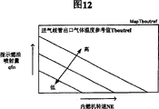
Figure 12 is the chart that is used for determining intake manifold Outlet Gas Temperature reference value, and CPU shown in Figure 1 in carrying out program shown in Figure 9 is with reference to this gas temperature reference value;
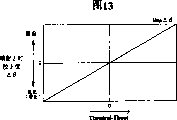
Figure 13 is the chart that is used for determining the injection timing corrected value, and CPU shown in Figure 1 in carrying out program shown in Figure 9 is with reference to this injection timing corrected value;
Figure 14 is the flow chart of expression CPU executive routine shown in Figure 1;
To such an extent as to Figure 15 is a chart of determining target egr rate (EGR leads) according to the CPU reference of the combustion engine control of first embodiment's a modification;
To such an extent as to Figure 16 is the chart that target boost pressure is determined in CPU reference shown in Figure 1; With
Figure 17 is the chart that concerns between expression cooling effectiveness η egr and the EGR flow rate of gas Gegr, and the temperature T ex that uses waste gas circulation tube inlet EGR gas is as parameter.
Embodiment
The embodiment and the EGR control gear of internal-combustion engine (diesel engine) control gear that comprises EGR gas temperature estimating device according to the present invention are described below with reference to accompanying drawings.
Represented to Fig. 1 n-lustrative the unitary construction of system, combustion engine control wherein of the present invention is applied on the four-cylinder internal combustion engine (diesel engine) 10.This system comprises a body of the internal-combustion engine 20 that fuel oil supply system is arranged; A gas handling system 30, the firing chamber of gas being introduced body of the internal-combustion engine 20 individual cylinder; A vent systems 40 is from body of the internal-combustion engine 20 combustion gas; An EGR device 50 carries out waste gas circulation; With an electric control device 60.
Fuel injection valve 21 is placed on the individual cylinder top of body of the internal-combustion engine 20.Fuel injection valve 21 is connected in electric controller 60 electronically.In response to drive signal (corresponding to the index signal of indication fuel injection amount qfin) from electric controller 60, each fuel injection valve 21 is opened a preset time, inject high pressure fuel oil therefrom, this high pressure fuel is supplied with from the unshowned fuel oil injectionpump that is connected with fuel tank.
Gas handling system 30 comprises intake manifold 31, links to each other with the firing chamber separately of body of the internal-combustion engine 20 individual cylinder; Suction tude 32, with the upstream side branch pipe part of intake manifold 31 divide link to each other and and intake manifold 31 constitute gas-entered passageway (intake manifold 31 and suction tude 32 can be called as " suction tude " jointly); Air throttle 33 is rotatably mounted in the suction tude 32 and also can be rotated by air throttle actuator 33a; Interstage cooler 34 places between the suction tude 32 to be positioned at the upstream side of air throttle 33; The compressor 35a of turbosupercharger 35 places between the suction tude 32 to be positioned at the upstream side of interstage cooler 34; With air-strainer 36, be placed on the end portion of suction tude 32.
Vent systems 40 comprises gas exhaust manifold 41, links to each other with the individual cylinder of body of the internal-combustion engine 20; Outlet pipe 42 links to each other with the downstream side fluidic junction branch of gas exhaust manifold 41; The turbine 35b of turbosupercharger 35 and turbosupercharger air throttle 35c, they place between the outlet pipe 42; With diesel particulate filter 43 (hereinafter referred to as " DPNR "), place outlet pipe 42.Gas exhaust manifold 41 and outlet pipe 42 constitute the exhaust passage.
Turbosupercharger air throttle 35c links to each other with electric controller 60.In response to the drive signal from electric controller 60, turbosupercharger air throttle 35c changes the cross-section area of the exhaust passage that is used for waste gas outflow turbine 35b, thereby changes the actual volume of turbosupercharger 35.When the cross-section area of exhaust passage reduced by closing turbosupercharger air throttle 35c, boost pressure increased.On the contrary, when the cross-section area of exhaust passage increased by opening turbosupercharger air throttle 35c, boost pressure reduced.
DPNR43 is a filter unit, and it holds one by the porous material filter that forms of steinheilite and absorb the particulate matter that contains in the waste gas by filter by porous surface for example.In DPNR43, at least a metallic element of selecting from following metal is carried on the aluminium oxide as carrier together with platinum: alkali metal, for example potassium K, sodium Na, lithium Li and caesium Cs; Alkaline-earth metal, for example barium Ba and calcium Ca; And rare earth metal, for example lanthanum La and yttrium Y.So DPNR43 is also as storage minimizing type NO
xCatalyst elements is at absorption of N O
xThe back discharges the NO that is absorbed
xAnd reduce it.
EGR device 50 comprises waste gas circulation pipe 51, forms the passage (EGR passage) of waste gas circulation; EGR control valve 52 places waste gas circulation pipe 51; With EGR gas quench system (cooler for recycled exhaust gas) 53, place waste gas circulation pipe 51.
The part that waste gas circulation pipe 51 links to each other with the exhaust passage (gas exhaust manifold 41) of the upstream side that is positioned at turbine 35b is as the inlet of EGR gas (waste gas).The part that waste gas circulation pipe 51 links to each other with the gas-entered passageway (intake manifold 31) in the downstream side that is positioned at air throttle 33 is as the outlet of EGR gas.Waste gas circulation pipe 51 has been set up the contact between inlet (waste gas circulation tube inlet) and the outlet (outlet of waste gas circulation pipe), thereby forms EGR gas flow to outlet from inlet gas flow pipe.
When intake manifold 31 is considered to the gas flow pipe, its inlet is the attachment portion between intake manifold 31 and the waste gas circulation pipe 51, and the outlet of intake manifold 31 is to extend to the inlet air of firing chamber to flow into part (by inlet open and the opening of closing), links to each other with the firing chamber (cylinder) of internal-combustion engine 10 in this place's intake manifold 31.
EGR control valve 52 links to each other with electric controller 60.In response to the drive signal (the EGR control valve is opened indicated value SEGR) of electric controller 60, EGR control valve 52 changes circuit exhausted air quantity (waste gas circulation amount, EGR flow rate of gas), thereby control EGR as described below leads.
EGR gas quench system 53 has a passage that is formed on the there, is used for EGR gas and flows into the inlet of this device and leave from the outlet of this device.Further, EGR gas quench system 53 has a cooling cross section that is exposed to the EGR gas channel.As the cooling water of the internal-combustion engine of cooling liquid by the circulation of cooling cross section.
Electric controller 60 is microcomputers, and it comprises CPU61, a ROM62, RAM63, backup RAM64, interface 65 etc., and they interconnect by bus.The program that the ROM62 storage is carried out by CPU61, operation table (look-up table, mapping table), constant etc.RAM63 allows the CPU61 temporal data.The data of backup RAM64 when being stored in power opening state, even after power supply is turned off, also keep the data of being deposited.Interface 65 comprises AD converter.
Interface 65 links to each other with hot wire type air flowmeter 71 in being placed on suction tude 32; Fresh air temperature sensor (intake air temperature sensor) 72 is arranged in the gas-entered passageway between interstage cooler 34 and the air throttle 33; Air inlet pressure sensor 73, the downstream that is held in place air throttle 33 and waste gas circulation pipe 51 link to each other with gas-entered passageway in the gas-entered passageway of upstream a little; Engine speed sensor 74; Cooling-water temperature sensor 75; With accel sensor 76.Interface 65 receives and offers CPU61 from the signal separately of these sensors and the signal that is received.In addition, interface 65 links to each other with EGR control valve 52 with fuel injection valve 21, air throttle actuator 33a, turbosupercharger air throttle 35c; According to the drive signal of the indication of CPU61 output corresponding to these elements.
Hot wire type air flowmeter 71 is measured via the air-strainer 36 new mass flow rates (air inflow of time per unit, the amount of fresh air of time per unit) that suck the air (being fresh air) of suction tude 32, and produces signal Ga (fresh air flow rate) corresponding to the mass flow rate of fresh air.Fresh air temperature sensor 72 is measured the temperature (being the fresh air temperature) that enters the fresh air of suction tude 32 via air-strainer 36, and produces the signal Ta of expression fresh air temperature.Air inlet pressure sensor 73 produces the signal Pb (suction pressure, boost pressure) of the pressure in the expression gas-entered passageway.
Engine speed sensor 74 detects the rotational velocity of internal-combustion engine 10, and produces the signal of expression internal-combustion engine rotational speed NE.Engine speed sensor 74 also can detect the absolute crankangle of each cylinder.Cooling-water temperature sensor 75 detects the temperature of the cooling water of internal-combustion engine 10, and produces the signal THW that represents institute's detected temperatures.Accel sensor 76 detects the position of accelerator pedal AP, and produces the signal Accp that represents accelerator opening (accelerator position).
The combustion engine control that below explanation is had above-mentioned structure.The CPU61 of electric controller 60 repeats the program of calculating various values with predetermined interval, and this program such as Fig. 2 represent with the form of theory diagram, lead Ract thereby calculate actual EGR.Hereinafter, will this program be described one by one by block diagram.It should be noted that values more described below as shown in Figure 3.
Obtain actual EGR and lead Ract
Actual EGR leads Ract and enters the actual amount of the EGR gas of internal-combustion engine 10 cylinders by time per unit (this is actual EGR gas mass flow speed, being called " EGR flow rate of gas Gegr " hereinafter) all enter the actual amount (this is actual all gas mass flow rate, hereinafter referred to as " all gas flow rate Gcyl ") of cylinder and the value (Ract=Gegr/Gcyl) that obtains divided by time per unit.EGR flow rate of gas Gegr equals to deduct the amount of fresh air (this is an air mass flow rate, hereinafter referred to as " actual fresh air flow rate Gaact ") that time per unit enters cylinder and the value that obtains by all gas flow rate Gcyl.Thereby shown in block diagram B1, CPU61 calculates actual EGR according to following representation (1) and leads Ract.
Obtain actual fresh air flow rate Gaact
Therefore the actual fresh air flow rate Gaact that is used in the representation (1) postpones to change about the fresh air flow rate Ga that is surveyed by air flowmeter 71 in time, is generally equal to the value that the first order deferring procedure of surveying fresh air flow rate Ga by being used for obtains.Thereby CPU61 calculates the actual fresh air flow rate than Gaact according to following representation (2), and this representation (2) is represented at block diagram B2, is used to carry out the first order deferring procedure of the fresh air flow rate Ga that surveys.α is the constant of supposition between 0 to 1.It should be noted that, the actual fresh air flow rate Gaact that actual fresh air flow rate GaactGaact (n-1) expression that Gaact (n) expression is obtained by current calculating was obtained by former calculating calculates before this and is carrying out early than scheduled time of current calculating; The fresh air flow rate Ga measured when Ga (n) is illustrated in current calculate according to the output of air flowmeter 71.
Gaact(n)=α·Gaact(n-1)+(1-α)·Ga(n) …(2)
Obtain all gas flow rate Gcyl
As releasing from equation of state of gas, all gas flow rate Gcyl is assumed to a value corresponding to downstream suction tude internal pressure (suction pressure) Pb with temperature (intake temperature) Tbout of the gas that enters internal-combustion engine 10 cylinders of air throttle 33, and this all gas flow rate Gcyl also is necessary for the calculating of carrying out representation (1).Hereinafter, temperature (intake temperature) Tbout that enters the gas of internal-combustion engine 10 cylinders is called as " intake manifold Outlet Gas Temperature Tbout ".
In fact, all gas flow rate Gcyl is subjected to remaining in the influence of the gas flow in internal-combustion engine 10 cylinders.Thereby, shown in block diagram B3, deriving the formula shown in the following row representation (3) according to test, CPU61 calculates all gas flow rate Gcyl.In representation (3), a and b are the constants of the mutual coupling determined of experiment, and Tbase represents intake manifold Outlet Gas Temperature (reference temperature) after constant a and b determine.Suction pressure (boost pressure) Pb used in the representation (3) is obtained by air inlet pressure sensor 73.
Obtain real gas temperature T bout
In order to carry out the calculating of representation (3), must obtain intake manifold Outlet Gas Temperature Tbout.Shown in block diagram B4, CPU61 calculates intake manifold Outlet Gas Temperature Tbout according to following representation (4).
Tbout=Tbin-ηim·(Tbin-Twallim) …(4)
In representation (4),
Tbin represents the temperature of the mixed gas in the outlet side zone of EGR control valves 52 in the intake manifold 31; That is, the zone that EGR gas and fresh air mix mutually (hereinafter referred is " converging part " or " intake manifold inlet "), as shown in Figure 3, and the mixture temperature that enters the mouth of intake manifold is called " intake manifold gasinlet temperature Tbin " hereinafter;
Twallim represents that intake manifold 31 leads the tube wall temperature of corresponding suction valve from the intake manifold entrance extension, and hereinafter this tube wall temperature is called as " intake manifold tube wall temperature Twallim ";
η im represents the heat conductivity (cooling effectiveness) in intake manifold 31 zone of extension between intake manifold inlet and intake manifold outlet (by the inlet open and the part of closing), and hereinafter this heat conductivity is called as " intake manifold heat conductivity η im ".
Above-mentioned representation (4) has been considered the wall of intake manifold 31 and has been entered heat exchange between the gas of cylinder, and the heat exchange of the wall of intake manifold 31 and ambient air (intake manifold 31 air outside).These heat exchanges are represented with the right second (η im (Tbin-Twallim)).This value η im (Tbin-Twallim) is a temperature variation, and this temperature variation is corresponding to the value of expression air inlet (fresh air+EGR gas) temperature variation when inlet air passes through intake manifold 31.
Difference between the tube wall temperature of the heat exchange between gas (inlet air) and the gas flow duct (intake manifold 31) and the temperature of inlet gas and gas flow duct has very strong coherence (for example, proportionate relationship).In addition, heat conductivity can suitably be represented heat exchange and gas flow tube wall and the extraneous heat exchange between this gas and the gas flow duct tube wall.Therefore, above-mentioned structure can be simply and is inferred heat exchange accurately, thereby can infer the temperature variation analog value accurately.
Simultaneously, in order to obtain intake manifold Outlet Gas Temperature Tbout by representation (4), must obtain each value (Tbin, Twallim, η im) on representation (4) the right.The process that obtains these values will be according to base description independently.
Obtain intake manifold gasinlet temperature Tbin
Shown in block diagram B5, CPU61 calculates intake manifold gasinlet temperature Tbin according to following representation (5), and representation (5) is according to principle of conservation of energy.
Tbin=(Gaact·Ta·Cair+Gegr·Tegr·Cegr)/(Gall·Cave) …(5)
Each value on representation (5) the right will be described with reference to figure 3.
Gaact represents aforementioned actual fresh air flow rate, is obtained by above-mentioned block diagram B2 according to representation (2);
Ta represents aforementioned fresh air temperature, is recorded by fresh air temperature sensor 72.
Cair represents the specific heat (fresh air specific heat) of fresh air, is a constant that provides in advance.
Gegr represents aforementioned EGR flow rate of gas, is obtained by following method.
Tegr represents just at EGR gas and fresh air in the temperature of converging before partially mixed.Particularly, temperature T egr is the EGR gas temperature of EGR gas outlet, hereinafter be called as " waste gas circulation pipe outlet EGR gas temperature (EGR channel outlet EGR gas temperature) Tegr ", this EGR gas outlet is the attachment portion that waste gas circulation pipe 51 links to each other with gas-entered passageway.This waste gas circulation pipe outlet EGR gas temperature Tegr is obtained by following method.
Cegr represents the specific heat (the EGR specific heats of gases) of EGR gas, is prior given constant.
Gall represents total combined amount of EGR gas and fresh air; That is, actual fresh air flow rate Gaact and EGR flow rate of gas Gegr sum hereinafter are called as " intake manifold inlet gas flow rate Gall ".
Cave represents the specific heat (mixed gas specific heat) of EGR gas and fresh air mixture, is a prior given constant.
In order to obtain intake manifold gasinlet temperature Tbin with representation (5), must obtain waste gas circulation pipe outlet EGR gas temperature Tegr, EGR flow rate of gas Gegr and intake manifold inlet gas flow rate Gall.The process that obtains these values will be according to base description independently.
Obtain waste gas circulation pipe outlet EGR gas temperature Tegr
Shown in block diagram B6, CPU61 calculates waste gas circulation pipe outlet EGR gas temperature Tegr according to following representation (6).Block diagram B6 EGR gas temperature estimating device for export.
Tegr=Tex-ηegr·(Tex-THW) …(6)
In representation (6), the EGR gas temperature that Tex is illustrated near waste gas circulation pipe 51 inlets the attachment portion between waste gas circulation pipe 51 and the gas exhaust manifold 41 (promptly, near the attachment portion between gas exhaust manifold 41 and the waste gas circulation pipe 51 exhaust gas temperature), hereinafter be called as " waste gas circulation tube inlet EGR gas temperature (EGR feeder connection EGR gas temperature) Tex ";
η egr represents the cooling effectiveness (heat conductivity) of EGR gas quench system 53; With
THW represents the cooling water temperature of internal-combustion engine 10, because the cooling liquid of EGR gas quench system 53 is cooling water of internal combustion engine, this temperature equals coolant temperature Treibai.
Above-mentioned representation (6) has been considered the heat exchange between the EGR gas of the EGR gas quench system 53 (its cooling cross section) and the EGR gas quench system 53 of flowing through.That is to say that representation (6) the right second (η egr (Tex-THW)) is temperature variation, this temperature variation is corresponding to the value of expression when the temperature variation of EGR gas stream during through EGR gas quench system 53.
In fact, interim when the part of EGR gas flows between the time point of the time point of waste gas circulation pipe 51 inlets and the outlet that EGR gas arrives waste gas circulation pipe 51 one section, the wall generation heat exchange of each part of EGR gas and waste gas circulation pipe 51.Yet it is quite little that the heat exchange amount between the wall of EGR gas and waste gas circulation pipe 51 is compared with respect to the heat exchange amount between EGR gas and the EGR gas quench system 53.Thereby representation (6) the right second (η egr (Tex-THW)) is substantially equal to be illustrated in the value that enters waste gas circulation pipe 51 inlets and arrive the variation of EGR gas temperature in period between 51 outlets of waste gas circulation pipe.
Simultaneously, in order to obtain waste gas circulation pipe outlet EGR gas temperature Tegr with representation (6), must obtain the cooling effectiveness η egr of above-mentioned waste gas circulation tube inlet EGR gas temperature Tex and above-mentioned EGR gas quench system.The process that obtains these values will be according to base description independently.
Obtain waste gas circulation tube inlet EGR gas temperature Tex
Shown in block diagram B8 and B9, CPU61 calculates waste gas circulation tube inlet EGR gas temperature Tex (exhaust gas temperature Tex) according to following representation (7).Block diagram B8 and B9 obtain device as the EGR gas temperature.
Tex=fTex(XTex) (7)
XTex=Gf
a/Gaact
Or XTex=(Gf
a/ Gaact) (Pb/Pex)
Or XTex=Gf Φ
Or XTex=Gf Φ (Pb/Pex)
Φ=Gf/Ga
Gf wherein: the fuel injection amount of time per unit (g/s);
Gaact: actual fresh air flow rate (g/s);
Pb: boost pressure;
Pex: gas exhaust manifold gas pressure;
Φ: flow rate is than (etc. price ratio);
A: constant.
In representation (7), time per unit fuel injection amount Gf can obtain (for example, Gf=kGfqfinNE (kGf: constant)) shown in the block diagram BP3 of Fig. 4 according to indication fuel injection amount qfin and internal-combustion engine rotational speed NE;
Actual fresh air flow rate Gaact is obtained by above-mentioned block diagram B2 according to representation (2);
Boost pressure Pb is suction pressure Pb, is obtained by air inlet pressure sensor 73; And
Gas exhaust manifold gas pressure Pex is obtained by following method.
Above-mentioned representation (7) is according to a discovery, promptly " waste gas circulation tube inlet EGR gas temperature Tex largely depends on the energy (giving birth to heat) that supplies to cylinder, and the heat transferred gas that produces in the cylinder ".The energy and the fuel injection amount Gf that supply to cylinder have very strong coherence.In addition, (actual fresh air flow rate Gaact does not help to give birth to hot the heat that produces in the cylinder with actual fresh air flow rate Gaact to the transmission of gas, but help to reduce exhaust gas temperature), or the flow rate relevant with the specific heats of gases has very strong coherence than Φ.Therefore, in representation (7), above-mentioned value is selectively as variable X Tex.
It should be noted that as the value (boost pressure Pb/ gas exhaust manifold gas pressure Pex) of variable X Tex and represent the easness (rest on easness gas exhaust manifold 41 in) of waste gas by gas exhaust manifold 41.The time that waste gas rests in the gas exhaust manifold 41 is long more, and the amount of heat transfer of waste gas and gas exhaust manifold 41 outsides is just many more.Thereby, by introducing (boost pressure Pb/ gas exhaust manifold gas pressure Pex), improved the accuracy of inferring of waste gas circulation tube inlet EGR gas temperature Tex as parameter.In addition, boost pressure Pb is relevant with the EGR gas flow, and when the EGR gas flow increased, the temperature when taking fire increased, thereby exhaust gas temperature Tex (waste gas circulation tube inlet EGR gas temperature Tex) increases.From this aspect, use boost pressure Pb to help to improve the accuracy of inferring of exhaust gas temperature Tex as parameter.
Determine function f Tex and constant a in the representation (7) for each type of internal combustion engine.Be the example of determining the process of function f Tex and constant a below.
(step 1) changes the operational condition of internal-combustion engine, will determine function f Tex and constant a at this; And measure required internal-combustion engine quantity of state (Gf, Gaact, Pb, Pex, Tex).
(step 2) according to measurement result, constant a determines like this: the actual measured value of variable X Tex and EGR gas temperature Tex shows very close coherence.It should be noted that when comprising flow rate and during as variable X Tex, ignore the adjustment (determining) of the value of constant a than the value of Φ.
(step 3) is according to the variable X Tex that determines according to determined constant a, and the actual measured value of EGR gas temperature Tex, determines function f Tex.
Fig. 5 be illustrated in select under the situation of Gf Φ (Pb/Pex) as variable X Tex, an example of the relation between the waste gas circulation tube inlet EGR gas temperature Tex of variable X Tex and actual measurement.In this case, function f Tex is following determines.
Tex=fTex(XTex)=545.9XTex
0.3489
Obtain gas exhaust manifold gas pressure Pex
Under the situation of the variable that comprises gas exhaust manifold gas pressure Pex, must obtain gas exhaust manifold gas pressure Pex as the variable X Tex of above-mentioned representation (7).Shown in the theory diagram of Fig. 4, CPU61 calculates gas exhaust manifold gas pressure Pex according to following representation (8).
Gf wherein: the fuel injection amount of time per unit (g/s);
Gaact: actual fresh air flow rate (g/s);
Pb: boost pressure;
Kvn: the solar term coefficient of variable volume turbosupercharger;
Avn: the aperture of variable volume turbosupercharger (0-100%);
Avn: positive constant.
In representation (8), fuel injection amount Gf obtains according to indication fuel injection amount qfin and internal-combustion engine rotational speed NE, shown in the block diagram BP3 of Fig. 4;
The actual fresh air flow rate is obtained by above-mentioned block diagram B2 according to representation (2);
Boost pressure Pb is suction pressure Pb, is obtained by air inlet pressure sensor 73; And
The aperture Avn of variable volume turbosupercharger is with reference to the determined value of chart, shown in the block diagram BP4 of Fig. 4, wherein indicates fuel injection amount qfin and internal-combustion engine rotational speed NE as independent variable.
CPU61 offers turbosupercharging air throttle 35c to drive signal by this way: the aperture of turbosupercharging air throttle 35c is consistent with value Avn.In addition, in block diagram BP5, constant avn adds among the aperture Avn of variable volume turbosupercharger, thereby aperture Avn is converted into the variable volume turbosupercharger solar term COEFFICIENT K vn in the representation (8).It should be noted that as described belowly, target boost pressure and determined value Avn can be set like this: actual supercharge pressure becomes and equals target boost pressure.
Above-mentioned representation (8) is based on this discovery: " gas exhaust manifold gas pressure Pex has very strong coherence with the gas flow (Gaact+Gf) that flows into cylinder, aperture Avn and the boost pressure of turbosupercharging air throttle 35c, and boost pressure has been represented the impedance of the turbine 35b of turbosupercharger 35 ".
For every kind of type of internal combustion engine, determine the function f Pex and the constant avn of representation (8).Be an example determining the process of function f Pex and constant avn below.
(step 1) changes the operational condition of internal-combustion engine, will determine function f Pex and constant avn at this; And measure required internal-combustion engine quantity of state (Gf, Gaact, Pb, Avn, Pex).
(step 2) according to measurement result, constant avn determines like this: variable X Pex and gas exhaust manifold gas pressure Pex show very close coherence.
(step 3) is according to the variable X Pex that determines according to determined constant avn, and the actual measured value of gas exhaust manifold gas pressure Pex, determines function f Pex.
Fig. 6 represents to be used in the above described manner determining the measured value of function f Pex.In this case, function f Pex determines by the expression of following representation (9).As mentioned above, in the present embodiment, exhaust pressure Pex can not use back pressure transducer and obtains, thereby has reduced the cost of this device.
Pex=fPex(XPex)=-2·10
-8·XPex
2+0.059·XPex+100.59 …(9)
By said process, can obtain to obtaining the required various values (Gf, Gaact, Pb, Pex) of variable X Tex of representation (7).Thereby by carrying out the calculating according to representation (7), CPU61 obtains waste gas circulation tube inlet gas temperature Tex (exhaust gas temperature Tex).Simultaneously, in order to obtain waste gas circulation pipe outlet EGR gas temperature Tegr with representation (6), also must obtain the cooling effectiveness η egr of EGR gas quench system.
Obtain the cooling effectiveness η egr of EGR gas quench system
Shown in the block diagram B10 of Fig. 2, CPU61 calculates the cooling effectiveness η egr of EGR gas quench system according to following representation (10).Block diagram B10 obtains device (estimating device) as the cooling unit cooling effectiveness.
ηegr=fηegr(Gegr/Tex) …(10)
Shown in representation (10),, must obtain above-mentioned waste gas circulation tube inlet EGR gas temperature Tex and EGR flow rate of gas Gegr in order to obtain the cooling effectiveness η egr of EGR gas quench system.Waste gas circulation tube inlet EGR gas temperature Tex is obtained by block diagram B8 and B9 according to above-mentioned representation (7).EGR flow rate of gas Gegr according to following expression (11) by below the block diagram B12 of explanation being obtained.
It should be noted that value (EGR flow rate of gas analog value) corresponding to EGR flow rate of gas Gegr can be used as the EGR flow rate of gas Gegr in the representation (10).For example, in the precalculated position of waste gas circulation pipe 51, EGR flow rate of gas Gegr can replace with EGR gas flow rates Vegr.Because the shape of EGR passage (the EGR passage is formed by waste gas circulation pipe 51 and EGR gas quench system 53) is known, so EGR flow rate of gas Gegr can infer according to EGR gas flow rates Vegr.This is the reason that EGR flow rate of gas Gegr can replace with EGR gas flow rates Vegr.EGR gas flow rates Vegr can directly be obtained by the flowing velocity sensor that is positioned in the waste gas circulation pipe 51.
Determine function f η egr in the representation (10) at every kind of type of internal combustion engine.Be an example determining function f η egr process below.
(step 1) changes the operational condition of internal-combustion engine, will determine function f η egr at this; And measure required internal-combustion engine quantity of state (Gegr, Tex, f η egr).
According to measurement result, the relation between η egr and the Gegr/Tex is determined with chart shown in Figure 7 (step 2).
(step 3) function f η egr determines according to the chart of formulating in the step 2.
As shown in figure 17, when waste gas circulation tube inlet EGR gas temperature Tex changed, the relation between cooling effectiveness η egr and the EGR flow rate of gas Gegr also changed.On the contrary, as shown in Figure 7, cooling effectiveness η egr and EGR flow rate of gas Gegr are well-determined divided by the merchant's (Gegr/Tex) of waste gas circulation tube inlet EGR gas temperature Tex relation, and be irrelevant with waste gas circulation tube inlet EGR gas temperature Tex.In other words, general and waste gas circulation tube inlet EGR gas temperature Tex is proportional because experiment discloses cooling effectiveness η egr, so function f η egr can be is simply obtained by cooling effectiveness η egr during as variable by use value (Gegr/Tex).
In this device, above-mentioned function f η egr is stored in ROM62 with the form of function, or the data of being made up of the combination of the value of Gegr/Tex and η egr are stored among the ROM62 with the form of the value of operation table (one dimension mapping table); The actual cooling effectiveness η egr that obtains obtains according to the actual value of Gegr/Tex and the function exclusive disjunction table of being stored.It should be noted that when electric controller 60 has remaining computing capability and/or storage volume, use such method: when the operational condition of internal-combustion engine changes, measure the value of Gegr, Tex and η egr; Measured data are stored among the ROM62 with the form of operation table Map η egr (two-dimensional map table); And actual cooling effectiveness η egr obtains according to actual EGR flow rate of gas Gegr, actual waste gas circulation tube inlet EGR gas temperature Tex and the operation table Map η egr that stored.Select as another kind, can use such method:, obtain to be used for determining the function gTex (Gegr) of cooling effectiveness η egr and being stored in ROM by EGR flow rate of gas Gegr for each waste gas circulation tube inlet EGR gas temperature Tex; According to actual waste gas circulation tube inlet EGR gas temperature Tex, from a plurality of function gTex that store, select eigenfunction gTex; And obtain actual cooling effectiveness η egr by selected function gTex and actual EGR flow rate of gas Gegr.
By above process, obtain the cooling effectiveness η egr and the cooling water temperature THW (coolant temperature Treibai) of waste gas circulation tube inlet EGR gas temperature Tex, EGR gas quench system, these all be carry out according to the calculating of the block diagram B6 of representation (6) needed.Therefore, CPU61 can enough representations (6) obtain waste gas circulation pipe outlet EGR gas temperature Tegr.At present, need above-mentioned variable EGR flow rate of gas Gegr and intake manifold inlet gas flow rate Gall to be used to carry out the calculating of representation (5).These values of following acquisition.
Obtain EGR flow rate of gas Gegr
EGR flow rate of gas Gegr can be obtained by draught head (Pex-Pb) and the EGR control valve aperture indicated value SEGR by EGR control valve 52, and SEGR represents the aperture of EGR control valve 52.That is to say that shown in block diagram B12, CPU61 calculates EGR flow rate of gas Gegr according to following representation (11).Block diagram B 12 obtains device as the analog value of EGR flow rate of gas.It should be noted that function f Gegr is obtained and is stored among the ROM62 by experiment in advance.
Gegr=fGegr(Pex-Pb,SEGR) …(11)
In representation (11), gas exhaust manifold gas pressure Pex is obtained by the block diagram BP1 of Fig. 4 according to above-mentioned representation (8).Boost pressure Pb is obtained by air inlet pressure sensor 73.EGR control valve aperture indicated value SEGR is the indicated value that CPU61 offers EGR control valve 52.In this case, replace EGR control valve aperture indicated value SEGR, can use signal from the sensor of the aperture (lifting capacity) that detects EGR control valve 52.
Obtain intake manifold inlet gas flow rate Gall
As mentioned above, intake manifold inlet gas flow rate Gall is actual fresh air flow rate Gaact and EGR flow rate of gas Gegr sum.Shown in block diagram B13, CPU61 calculates intake manifold inlet gas flow rate Gall according to following representation (12).
Gall=Gaact+Gegr …(12)
Obtain actual fresh air flow rate Gaact in the representation (12) according to above-mentioned representation (2) by block diagram B2.Obtain EGR flow rate of gas Gegr according to above-mentioned representation (11) by block diagram B12.
By said process, obtain to carry out the desired various values of calculating of representation (5).Thereby CPU61 obtains intake manifold gasinlet temperature Tbin according to representation (5) by block diagram B5.Simultaneously, at present, need above-mentioned variable intake manifold tube wall temperature Twallim and intake manifold heat conductivity η im, be used for acquisition intake manifold Outlet Gas Temperature Tbout by representation (4) (block diagram B4).These values of following acquisition.
Obtain intake manifold tube wall temperature Twallim
The cooling water temperature THW that intake manifold tube wall temperature Twallim and cooling-water temperature sensor 75 are surveyed has very strong coherence.Therefore, when using function f 1 Twallim, by block diagram B14, CPU61 calculates intake manifold tube wall temperature Twallim according to following representation (13), and this function f 1 Twallim provides the value that increases with cooling water temperature THW.It should be noted that function f 1Twallim is obtained and is stored among the ROM62 by experiment in advance.
Twallim=f1Twallim(THW) …(13)
Obtain intake manifold heat conductivity η im
Shown in block diagram B15 and B16, CPU61 calculates intake manifold heat conductivity η im according to following representation (14).
In representation (14), Vim represents the gas flow rates (hereinafter referred to as " intake manifold gas flow rates Vim ") in the intake manifold.Because the shape of known intake manifold 31, shown in above-mentioned representation (14), intake manifold gas flow rates Vim can obtain according to intake manifold inlet gas flow rate Gall.Intake manifold inlet gas flow rate Gall is obtained by block diagram B13 according to above-mentioned representation (12).
It should be noted that intake manifold gas flow rates Vim can directly be obtained by the output of the flowing velocity sensor that is positioned over intake manifold 31.Though intake manifold gas flow rates Vim is as the variable of the function f η im of representation (14), intake manifold inlet gas flow rate Gall also can be used as variable and replaces intake manifold gas flow rates Vim.
Above-mentioned representation (14) is based on this discovery: " intake manifold heat conductivity η im is subjected to the influence of the gas flow rates Vim in the intake manifold 31 largely ".Though in representation (14), in order to obtain intake manifold heat conductivity η im, cooling water temperature THW is also as variable, yet can not use cooling water temperature THW, but, obtain intake manifold heat conductivity η im by with the function (η im=f η im (Vim)) of intake manifold gas flow rates Vim or the function (im=f η im (Gall)) of intake manifold inlet gas flow rate Gall.
Because function f η im changes with the type of internal-combustion engine, so by the contrast actual measured value, at every type of definite function f η im.Fig. 8 represents the actual measured value at a kind of specific engine.In the example of Fig. 8, the following row representation of function f η im (15) and determining.
ηim=fηim(Vim,THW)
=(-0.000061·THW
2+0.003378·THW-0.180831)·In(Vim)
+(0.000048·THW
2-0.000227·THW+0.509251) …(15)
By said process, obtain to carry out the required various values (Tbin, η im, Twallim) of calculating of representation (4).So CPU61 obtains intake manifold Outlet Gas Temperature Tbout according to representation (4) by block diagram B4.Thereby CPU61 is obtained all gas flow rate Gcyl of all air inflows of expression internal-combustion engine 10 by block diagram B3 according to representation (3).Thereby CPU61 obtains actual EGR according to representation (1) by block diagram B1 and leads Ract.
To describe the various controls of internal-combustion engine 10 below, the various values that obtain in the utilization said method are carried out these control.
Fuel injection amount control and fuel injection timing control
CPU61 repeats program shown in the flow chart of Fig. 9 by predetermined interval, and this procedural application is in control fuel injection amount and fuel injection timing.Therefore, be scheduled to just constantly when arriving, CPU61 begins this process from step 900, obtains indication fuel injection amount qfin to such an extent as to advance to step 905 then from accelerator opening Accp, internal-combustion engine rotational speed NE and operation table (mapping table) Mapqfin, as shown in figure 10.Operation table Mapqfin has determined the relation between accelerator opening Accp and internal-combustion engine rotational speed NE and the indication fuel injection amount qfin; And be stored among the ROM62.
Subsequently, CPU61 advances to step 910 so that determine reference fuel injection timing finj by indication fuel injection amount qfin, internal-combustion engine NE and operation table Mapfinj, as shown in figure 11.Operation table Mapfinj has determined the relation between indication fuel injection amount qfin and internal-combustion engine NE and the reference fuel injection timing finj; And be stored among the ROM62.
CPU61 advances to step 915 so that determine intake manifold Outlet Gas Temperature reference value Tboutref by indication fuel injection amount qfin, internal-combustion engine NE and operation table MapTboutref subsequently, as shown in figure 12.This operation table MapTboutref has determined the relation between indication fuel injection amount qfin and internal-combustion engine NE and the intake manifold Outlet Gas Temperature reference value Tboutref; And be stored among the ROM62.This intake manifold Outlet Gas Temperature reference value Tboutref represents when using reference fuel injection timing finj the gas temperature Tbout in the outlet of intake manifold 31, this reference fuel injection timing finj use shown in Figure 11 in conjunction with indication fuel injection amount qfin and internal-combustion engine rotational speed NE arithmograph and determine.
Next, CPU61 advances to step 920 so that determine the injection timing correction value delta theta according to the intake manifold Outlet Gas Temperature reference value Tboutref, the intake manifold Outlet Gas Temperature reference value Tboutref that determine in the step 915 and poor (Tboutref-Tbout) between the actual intake manifold Outlet Gas Temperature Tbout and operation table Map Δ θ, as shown in figure 13.Wherein Tbout is obtained by block diagram B4 shown in Figure 2.Operation table Map Δ θ has determined the relation between difference (Tboutref-Tbout) and the injection timing correction value delta theta; And be stored among the ROM62.
Subsequently, thereby advancing to step 925, CPU61 obtains final injection timing finjfinal by injection timing correction value delta theta correction reference fuel injection timing finj.As mentioned above, above-mentioned steps 915 to 925 is proofreaied and correct injection timing according to intake manifold Outlet Gas Temperature Tbout.In this case, can see clearly from Figure 13, when intake manifold Outlet Gas Temperature Tbout becomes when being higher than intake manifold Outlet Gas Temperature reference value Tboutref, injection timing correction value delta theta hypothesis is a negative value corresponding to the difference between them, so final injection timing finjfinal shifts to postponing a side.On the contrary, when intake manifold Outlet Gas Temperature Tbout becomes when being lower than intake manifold Outlet Gas Temperature reference value Tboutref, injection timing correction value delta theta hypothesis corresponding to the difference between them be on the occasion of, so final injection timing finjfinal is to side transfer in advance.
The reason of determining injection timing with said method is as follows.When intake manifold Outlet Gas Temperature Tbout was very high, the combustibility of fuel oil was better than the low situation of temperature T bout.Therefore, even postpone the fuel injection timing, combustibility can variation yet, and can reduce NO
xDischarging.On the contrary, when intake manifold Outlet Gas Temperature Tbout is very low, the flammable variation of fuel oil.Therefore, fuel injection timing in advance is to keep flammable.This operation has improved the output performance of internal-combustion engine 10 and has reduced NO
xDischarging.
In step 930 subsequently, CPU61 determines whether current time is consistent with the determined final injection timing finjfinal of step 925.When current time was consistent with final injection timing finjfinal, CPU61 advanced to step 935 so that make the fuel injection valve 21 of the cylinder that reaches injection timing spray the fuel oil of quantity corresponding to the indication fuel injection amount qfin that determines in the step 905.Subsequently, thus CPU61 advances to step 995 finishes present procedure.When the definite result in the step 930 is "No",, CPU61 finishes present procedure thereby directly advancing to step 995.By said process, realize fuel injection amount control and fuel injection timing control.
EGR control
Next describe EGR and lead control.CPU61 repeats program shown in the flow chart of Figure 14 with predetermined interval, and this program is suitable for controlling EGR and leads.Therefore, be scheduled to just constantly when reaching, CPU61 begins this process from step 1400, advances to step 1405 then so that determine target oxygen intake concentration O2tgt by the operation table MapO2tgt shown in the block diagram of indication fuel injection amount qfin, the current time internal-combustion engine rotational speed NE of current time and current step.Operation table MapO2tgt determines the relation of indication fuel injection amount qfin and internal-combustion engine rotational speed NE and target oxygen intake concentration O2tgt.
Subsequently, in step 1410, CPU61 is by the supply amount of fuel Q in indication fuel injection amount qfin and the internal-combustion engine rotational speed NE acquisition time per unit; In step 1415 subsequently, CPU61 obtains excess air by the representation shown in the block diagram of current step (λ=k λ Gaact/Q) and compares λ.K λ is a constant.In step 1420 subsequently, the excess air that CPU61 obtains according to the target oxygen intake concentration O2tgt that determines in above-mentioned steps 1405, in above-mentioned steps 1415 obtains target EGR than the representation shown in the block diagram of λ and step 1420 (Rtgt=λ (pO2tgt+q), wherein p and q are constants) and leads Rtgt.It should be noted that oxygen intake concentration, EGR lead and excess air than between relation at length disclosed, for example, in Japanese Unexamined Patent Publication No 10-141147.
Next, in step 1425, CPU61 determines that the actual EGR that obtains leads Ract and whether leads Rtgt greater than the target EGR that obtains in above-mentioned steps 1420 in block diagram B1 shown in Figure 2.When the result who determines in the step 1425 was "Yes", CPU61 advanced to step 1430 so that predetermined amounts is closed EGR control valve 52, led thereby reduce EGR.Subsequently, thus CPU61 advances to step 1495 finishes present procedure.On the contrary, when the result who determines in the step 1425 was "No", CPU61 advanced to step 1435 so that predetermined amounts is opened EGR control valve 52, led thereby increase EGR.Subsequently, CPU61 advances to step 1495.Because it is control like this that aforesaid operations, EGR lead: actual oxygen intake concentration becomes and equals target oxygen intake concentration O2tgt, thereby reduce NO
xDischarging with flue dust.
Lead in the control at the EGR by program shown in Figure 14, CPU61 leads Rtgt and controls EGR and lead by obtaining target oxygen intake concentration O2tgt and this target oxygen intake concentration O2tgt being converted into target EGR.Yet EGR leads also and can followingly control.By reality indication fuel injection amount qfin, actual internal-combustion engine rotational speed NE and operation table MapRtgt and definite relation of indicating fuel injection amount qfin and internal-combustion engine rotational speed NE and target EGR to lead Rtgt shown in Figure 15, directly obtain target EGR and lead Rtgt; The aperture of EGR control valve 52 is controlled like this: actual EGR leads Ract and becomes and equal target EGR and lead Rtgt.
Boost pressure control
Next, boost pressure control will be described.CPU61 repeats the program of not showing that is used to control boost pressure with predetermined interval, so that determine target boost pressure Pbtgt with predetermined interval by current indication fuel injection amount qfin, current internal-combustion engine rotational speed NE and operation table MapPbtgt shown in Figure 16.Operation table MapPbtgt determines the relation between indication fuel injection amount qfin and internal-combustion engine rotational speed NE and the target boost pressure Pbtgt; And be stored among the ROM62.
Subsequently, the more determined target boost pressure Pbtgt of CPU61 and by air inlet pressure sensor 73 resulting actual supercharge pressure Pb, and control the aperture of turbosupercharger air throttle 35c like this: actual supercharge pressure Pb equals target boost pressure Pbtgt.Carry out boost pressure control by this way.
As mentioned above, in the embodiment of combustion engine control of the present invention, because being the analog values according to waste gas circulation tube inlet EGR gas temperature and EGR flow rate of gas, the cooling effectiveness of EGR gas quench system 53 obtains, so improved the accuracy of inferring of waste gas circulation pipe outlet EGR gas temperature.In addition, infer intake manifold Outlet Gas Temperature Tbout because having considered the mixed gas (air inlet) of intake manifold 31 and fresh air and EGR gas, so also improved the accuracy of inferring of intake manifold Outlet Gas Temperature Tbout.As a result, can accurately infer EGR leads.
The present invention is not limited only to the foregoing description, and can improve by different way within the scope of the invention.For example, gas exhaust manifold gas pressure Pex can obtain according to the output value of back pressure transducer, and this back pressure transducer is placed near gas exhaust manifold 41 and the position that waste gas circulation pipe 51 links to each other.
Claims (6)
1. internal-combustion engine EGR gas temperature estimating device, this internal-combustion engine has one and is connected the waste gas circulation pipe between exhaust passage and the gas-entered passageway, an EGR control valve and an EGR gas quench system that places the waste gas circulation pipe that places this waste gas circulation pipe and be suitable for controlling the EGR flow rate of gas that flows into the waste gas circulation pipe, and this EGR gas temperature estimating device comprises:
Be used to obtain the device of EGR gas quench system inlet side EGR gas temperature;
Be used to obtain device corresponding to the analog value of the EGR flow rate of gas of the waste gas circulation pipe of flowing through;
Cooling effectiveness obtains device, be used for according to by the analog value that is obtained divided by the value that the EGR gas temperature of the EGR gas quench system inlet side that is obtained obtains, obtain cooling effectiveness; With
Outlet EGR gas temperature estimating device, the EGR gas temperature of the outlet side that is used for inferring the EGR gas quench system according to the EGR gas temperature and the acquired cooling effectiveness of EGR gas quench system inlet side.
2. internal-combustion engine EGR gas temperature estimating device according to claim 1, comprise that also coolant temperature obtains device, be used to obtain the temperature of the freezing mixture of EGR gas quench system, its middle outlet EGR gas temperature estimating device is inferred the EGR gas temperature of the outlet side of EGR gas quench system.
3. internal-combustion engine EGR gas temperature estimating device according to claim 2, it is characterized in that, difference between the EGR gas temperature of the EGR gas quench system inlet side that outlet EGR gas temperature estimating device obtains by using and the coolant temperature that is obtained multiply by cooling effectiveness infers the EGR gas temperature and changes, and deducts the EGR gas temperature of being inferred by the EGR gas temperature from EGR gas quench system inlet side and change the EGR gas temperature of inferring EGR gas quench system outlet side.
4. internal-combustion engine EGR gas temperature estimating device, this internal-combustion engine have one be connected waste gas circulation pipe between exhaust passage and the gas-entered passageway, one place this waste gas circulation pipe and be suitable for controlling the EGR control valve of the EGR flow rate of gas that flows into the waste gas circulation pipe and attachment portion that one places the waste gas circulation pipe is connected to the exhaust passage at EGR control valve and waste gas circulation pipe waste gas circulation pipe between the EGR gas quench system, this EGR gas temperature estimating device comprises:
Inlet EGR gas temperature obtains device, and the EGR gas temperature that is used to obtain place, EGR gas access is as waste gas circulation tube inlet EGR gas temperature, and this EGR gas access is the attachment portion that the waste gas circulation pipe is connected to the waste gas circulation pipe of exhaust passage;
The analog value of EGR flow rate of gas obtains device, is used to obtain the analog value corresponding to the EGR flow rate of gas of the EGR gas flow speed of the waste gas circulation pipe of flowing through;
Cooling effectiveness obtains device, is used for the value that obtains divided by the waste gas circulation tube inlet EGR gas temperature that is obtained according to the analog value by the EGR flow rate of gas that is obtained, obtains the cooling effectiveness of EGR gas quench system; With
Outlet EGR gas temperature estimating device, be used for according to the waste gas circulation tube inlet EGR gas temperature and the acquired cooling effectiveness that are obtained, the EGR gas temperature of inferring the EGR gas outlet is as waste gas circulation pipe outlet EGR gas temperature, and this EGR gas outlet is the attachment portion of the waste gas circulation pipe that links to each other with gas-entered passageway of waste gas circulation pipe.
5. internal-combustion engine EGR gas temperature estimating device according to claim 4, comprise that also coolant temperature obtains device, be used to obtain the temperature of the freezing mixture of EGR gas quench system, its middle outlet EGR gas temperature estimating device is inferred the EGR gas temperature of waste gas circulation pipe outlet according to the coolant temperature that is obtained.
6. internal-combustion engine EGR gas temperature estimating device according to claim 5, it is characterized in that, difference between the EGR gas temperature of the waste gas circulation tube inlet that outlet EGR gas temperature estimating device obtains by using and the coolant temperature that is obtained multiply by cooling effectiveness infers the EGR gas temperature and changes, and deducts the EGR gas temperature of being inferred by the EGR gas temperature from the waste gas circulation tube inlet and change the EGR gas temperature of inferring the outlet of waste gas circulation pipe.
Applications Claiming Priority (2)
| Application Number | Priority Date | Filing Date | Title |
|---|---|---|---|
| JP2002320400A JP3751930B2 (en) | 2002-11-01 | 2002-11-01 | EGR gas temperature estimation device for internal combustion engine |
| JP320400/2002 | 2002-11-01 |
Publications (2)
| Publication Number | Publication Date |
|---|---|
| CN1499066A CN1499066A (en) | 2004-05-26 |
| CN1311153C true CN1311153C (en) | 2007-04-18 |
Family
ID=32089626
Family Applications (1)
| Application Number | Title | Priority Date | Filing Date |
|---|---|---|---|
| CNB2003101045529A Expired - Fee Related CN1311153C (en) | 2002-11-01 | 2003-10-31 | EGR-gas temp estimation appts. for I.C. engine |
Country Status (4)
| Country | Link |
|---|---|
| US (1) | US6993909B2 (en) |
| EP (1) | EP1416139A3 (en) |
| JP (1) | JP3751930B2 (en) |
| CN (1) | CN1311153C (en) |
Families Citing this family (35)
| Publication number | Priority date | Publication date | Assignee | Title |
|---|---|---|---|---|
| US6848434B2 (en) * | 2003-03-17 | 2005-02-01 | Cummins, Inc. | System for diagnosing operation of an EGR cooler |
| EP1617056B1 (en) * | 2004-07-14 | 2014-10-22 | Honda Motor Co., Ltd. | Control system for internal combustion engine |
| JP4186899B2 (en) * | 2004-09-30 | 2008-11-26 | 株式会社日立製作所 | Exhaust gas recirculation control device |
| JP2006152891A (en) * | 2004-11-29 | 2006-06-15 | Denso Corp | Exhaust emission control device of internal combustion engine |
| JP4542489B2 (en) * | 2005-09-21 | 2010-09-15 | 株式会社豊田自動織機 | Exhaust manifold internal temperature estimation device for internal combustion engine |
| FR2894617B1 (en) | 2005-12-13 | 2008-02-15 | Renault Sas | METHOD OF ESTIMATING EXHAUST GAS TEMPERATURE BEFORE TURBINE. |
| FR2908825B1 (en) * | 2006-11-17 | 2009-01-30 | Renault Sas | ESTIMATION OF EXHAUST GAS TEMPERATURE OUTPUT OF EGR CIRCUIT OF COMBUSTION ENGINE |
| JP2008180180A (en) * | 2007-01-25 | 2008-08-07 | Toyota Motor Corp | Internal combustion engine, control method thereof, and vehicle |
| JP2009008463A (en) * | 2007-06-27 | 2009-01-15 | Hitachi Ltd | Apparatus and method for measuring quantity of recirculating gas flow of exhaust gas |
| US8342015B2 (en) * | 2007-09-20 | 2013-01-01 | Renault S.A.S. | Method for diagnosing the exchanger bypass flap in an exhaust gas recirculation circuit |
| FR2921426B1 (en) * | 2007-09-20 | 2014-02-14 | Renault Sas | METHOD FOR DIAGNOSING THE EXCHANGER DERIVATION FLAP IN AN EXHAUST GAS RECIRCULATION SYSTEM |
| US7824099B2 (en) * | 2007-11-29 | 2010-11-02 | Gm Global Technology Operations, Inc. | Accurate gas temperature estimation at transient conditions based on temperature sensor readings |
| JP5204609B2 (en) * | 2008-10-07 | 2013-06-05 | 株式会社豊田自動織機 | Engine control device |
| GB2473602B (en) * | 2009-09-09 | 2013-07-31 | Gm Global Tech Operations Inc | Method for the diagnosis of the EGR cooler efficiency in a diesel engine |
| US8201442B2 (en) * | 2009-09-25 | 2012-06-19 | Cummins Inc. | System and method for estimating EGR mass flow rates |
| US20110154821A1 (en) * | 2009-12-24 | 2011-06-30 | Lincoln Evans-Beauchamp | Estimating Pre-Turbine Exhaust Temperatures |
| JP5177463B2 (en) * | 2010-01-18 | 2013-04-03 | トヨタ自動車株式会社 | Gas state estimating apparatus for internal combustion engine |
| FR2965584B1 (en) * | 2010-10-05 | 2013-06-28 | Renault Sas | METHOD FOR DETERMINING A RECIRCULATED EXHAUST GAS RATE AT THE INPUT OF A CYLINDER OF AN INTERNAL COMBUSTION ENGINE AND ENGINE IMPLEMENTING SAID METHOD |
| US9127606B2 (en) * | 2010-10-20 | 2015-09-08 | Ford Global Technologies, Llc | System for determining EGR degradation |
| KR101251526B1 (en) * | 2011-06-13 | 2013-04-05 | 기아자동차주식회사 | Low pressure egr system and examining method for efficeincy of low egr cooler |
| US9062635B2 (en) | 2011-09-25 | 2015-06-23 | Cummins Inc. | System and method for estimating engine exhaust manifold operating parameters |
| JP5883289B2 (en) * | 2011-12-22 | 2016-03-09 | 日野自動車株式会社 | Anomaly detection method |
| KR101316875B1 (en) * | 2012-03-27 | 2013-10-10 | 기아자동차주식회사 | Apparatus for controling exhaust gas recirculation and method thereof |
| US9109518B2 (en) * | 2012-05-23 | 2015-08-18 | GM Global Technology Operations LLC | Method and apparatus for monitoring performance of EGR heat exchanger |
| CN104487690B (en) * | 2012-07-18 | 2017-09-29 | 日产自动车株式会社 | Internal combustion engine |
| JP2014185546A (en) * | 2013-03-22 | 2014-10-02 | Toyota Motor Corp | Control device of vehicle and control method |
| US9631585B2 (en) * | 2013-09-11 | 2017-04-25 | GM Global Technology Operations LLC | EGHR mechanism diagnostics |
| DE102014013284A1 (en) * | 2014-09-12 | 2016-03-17 | Man Truck & Bus Ag | Internal combustion engine, in particular gas engine, for a vehicle, in particular for a utility vehicle |
| US9528475B2 (en) * | 2014-11-11 | 2016-12-27 | Ford Global Technologies, Llc | Method and system for EGR control |
| CN105223023B (en) * | 2015-09-29 | 2017-07-28 | 安徽江淮汽车集团股份有限公司 | A kind of detection method of EGR gas temperatures and cooler for recycled exhaust gas cooling effectiveness |
| JP6265197B2 (en) * | 2015-11-26 | 2018-01-24 | トヨタ自動車株式会社 | Control device for internal combustion engine |
| CN107366579A (en) * | 2016-05-13 | 2017-11-21 | 宝沃汽车(中国)有限公司 | Control method, device and the vehicle of engine system |
| CN106321296B (en) * | 2016-08-31 | 2019-01-15 | 潍柴动力股份有限公司 | It is a kind of for adjusting the method and device of EGR exhaust temperature |
| JP6579081B2 (en) * | 2016-10-25 | 2019-09-25 | トヨタ自動車株式会社 | Exhaust gas recirculation device for internal combustion engine |
| CN112380707A (en) * | 2020-11-18 | 2021-02-19 | 潍柴动力股份有限公司 | Method and device for evaluating cooling performance of EGR cooler and electronic equipment |
Citations (3)
| Publication number | Priority date | Publication date | Assignee | Title |
|---|---|---|---|---|
| JPH11166452A (en) * | 1997-12-03 | 1999-06-22 | Nissan Motor Co Ltd | Cylinder intake gas temperature calculating device and egr controller for diesel engine |
| JP2001164999A (en) * | 1999-12-14 | 2001-06-19 | Toyota Motor Corp | Clogging sensing device of exhaust gas recirculation device |
| JP2002180889A (en) * | 2000-12-11 | 2002-06-26 | Toyota Motor Corp | Detection method of intake temperature after supercharging, operation controller and cooling abnormality detector for intercooler in supercharging internal combustion engine system |
Family Cites Families (11)
| Publication number | Priority date | Publication date | Assignee | Title |
|---|---|---|---|---|
| JP3518203B2 (en) * | 1996-11-14 | 2004-04-12 | トヨタ自動車株式会社 | Internal combustion engine with EGR device |
| US5732688A (en) * | 1996-12-11 | 1998-03-31 | Cummins Engine Company, Inc. | System for controlling recirculated exhaust gas temperature in an internal combustion engine |
| US6116083A (en) * | 1999-01-15 | 2000-09-12 | Ford Global Technologies, Inc. | Exhaust gas temperature estimation |
| US6085732A (en) * | 1999-01-25 | 2000-07-11 | Cummins Engine Co Inc | EGR fault diagnostic system |
| US6446498B1 (en) * | 1999-06-30 | 2002-09-10 | Caterpillar Inc. | Method for determining a condition of an exhaust gas recirculation (EGR) system for an internal combustion engine |
| US6347519B1 (en) * | 2000-03-31 | 2002-02-19 | Detroit Diesel Corporation | System and method for measuring recirculated exhaust gas flow in a compression-ignition engine |
| US6434476B1 (en) * | 2000-10-04 | 2002-08-13 | Detroit Diesel Corporation | High voltage fault discrimination for EGR temperature sensor |
| JP2002129996A (en) * | 2000-10-25 | 2002-05-09 | Toyota Motor Corp | Exhaust emission control device for internal combustion engine |
| JP2003155957A (en) * | 2001-09-04 | 2003-05-30 | Mitsubishi Motors Corp | Egr control device and egr control method |
| US6725847B2 (en) * | 2002-04-10 | 2004-04-27 | Cummins, Inc. | Condensation protection AECD for an internal combustion engine employing cooled EGR |
| US6622548B1 (en) * | 2002-06-11 | 2003-09-23 | General Motors Corporation | Methods and apparatus for estimating gas temperatures within a vehicle engine |
-
2002
- 2002-11-01 JP JP2002320400A patent/JP3751930B2/en not_active Expired - Fee Related
-
2003
- 2003-10-30 US US10/695,873 patent/US6993909B2/en not_active Expired - Fee Related
- 2003-10-30 EP EP03025045A patent/EP1416139A3/en not_active Withdrawn
- 2003-10-31 CN CNB2003101045529A patent/CN1311153C/en not_active Expired - Fee Related
Patent Citations (3)
| Publication number | Priority date | Publication date | Assignee | Title |
|---|---|---|---|---|
| JPH11166452A (en) * | 1997-12-03 | 1999-06-22 | Nissan Motor Co Ltd | Cylinder intake gas temperature calculating device and egr controller for diesel engine |
| JP2001164999A (en) * | 1999-12-14 | 2001-06-19 | Toyota Motor Corp | Clogging sensing device of exhaust gas recirculation device |
| JP2002180889A (en) * | 2000-12-11 | 2002-06-26 | Toyota Motor Corp | Detection method of intake temperature after supercharging, operation controller and cooling abnormality detector for intercooler in supercharging internal combustion engine system |
Non-Patent Citations (1)
| Title |
|---|
| 卡车废气再循环系统 李素华,重型汽车,第2卷第45期 1998 * |
Also Published As
| Publication number | Publication date |
|---|---|
| EP1416139A3 (en) | 2007-10-10 |
| JP3751930B2 (en) | 2006-03-08 |
| JP2004156457A (en) | 2004-06-03 |
| US6993909B2 (en) | 2006-02-07 |
| EP1416139A2 (en) | 2004-05-06 |
| US20040084030A1 (en) | 2004-05-06 |
| CN1499066A (en) | 2004-05-26 |
Similar Documents
| Publication | Publication Date | Title |
|---|---|---|
| CN1311153C (en) | EGR-gas temp estimation appts. for I.C. engine | |
| CN100343499C (en) | Suction air volume estimating device for internal combustion engine | |
| CN1270067C (en) | Apparatus for controlling internal combustion engine | |
| CN1541300A (en) | Excess air factor control of diesel engine | |
| CN1673507A (en) | Method of estimating the fuel/air ratio in a cylinder of an internal-combustion engine | |
| CN1657767A (en) | Ignition timing control for internal combustion engine | |
| US6877369B2 (en) | EGR-gas flow rate estimation apparatus for internal combustion engine | |
| CN1463322A (en) | Exhaust emission control device for I.C. engine | |
| CN1298983C (en) | Controller of internal combustion engine | |
| CN1403696A (en) | EGR controlling apparatus and EGR controlling method | |
| CN1796749A (en) | Engine control system | |
| CN1934345A (en) | Gas-mixture-ignition-time estimation apparatus for internal combustion engine and control apparatus for internal combustion engine | |
| CN1187862A (en) | Lambda control by skip fire of unthrottled gas fueled engines | |
| CN104500245B (en) | Method and device for determining and adjusting the ER EGR Rate of internal combustion engine | |
| CN1534180A (en) | Combustion control for IC engine | |
| CN1892006A (en) | Engine control apparatus | |
| CN1828031A (en) | Controller for internal combustion engine with supercharger | |
| CN1918382A (en) | Abnormality detection device for internal combustion engine | |
| CN101042066A (en) | Fuel control system for internal combustion engine | |
| EP1528241A3 (en) | Estimation of intake gas temperature in internal combustion engine | |
| CN1451861A (en) | Steam fuel exhausting controlling system | |
| CN1912370A (en) | Device for controlling engine rotation stop by estimating kinetic energy and stop position | |
| CN1538048A (en) | Exhaust purification system for internal conbustion engine | |
| CN1609428A (en) | Control apparatus and control method for internal combustion engine valve actuation | |
| CN1637264A (en) | Exhaust gas recirculation system for internal combustion engine |
Legal Events
| Date | Code | Title | Description |
|---|---|---|---|
| C06 | Publication | ||
| PB01 | Publication | ||
| C10 | Entry into substantive examination | ||
| SE01 | Entry into force of request for substantive examination | ||
| C14 | Grant of patent or utility model | ||
| GR01 | Patent grant | ||
| C17 | Cessation of patent right | ||
| CF01 | Termination of patent right due to non-payment of annual fee |
Granted publication date: 20070418 Termination date: 20111031 |