CN1309341C - Fetal oximetry system and sensor - Google Patents
Fetal oximetry system and sensor Download PDFInfo
- Publication number
- CN1309341C CN1309341C CNB988063042A CN98806304A CN1309341C CN 1309341 C CN1309341 C CN 1309341C CN B988063042 A CNB988063042 A CN B988063042A CN 98806304 A CN98806304 A CN 98806304A CN 1309341 C CN1309341 C CN 1309341C
- Authority
- CN
- China
- Prior art keywords
- inserted link
- pick
- circuit connector
- skirt
- lug
- Prior art date
- Legal status (The legal status is an assumption and is not a legal conclusion. Google has not performed a legal analysis and makes no representation as to the accuracy of the status listed.)
- Expired - Lifetime
Links
Images


Classifications
-
- A—HUMAN NECESSITIES
- A61—MEDICAL OR VETERINARY SCIENCE; HYGIENE
- A61B—DIAGNOSIS; SURGERY; IDENTIFICATION
- A61B5/00—Measuring for diagnostic purposes; Identification of persons
- A61B5/145—Measuring characteristics of blood in vivo, e.g. gas concentration, pH value; Measuring characteristics of body fluids or tissues, e.g. interstitial fluid, cerebral tissue
- A61B5/1455—Measuring characteristics of blood in vivo, e.g. gas concentration, pH value; Measuring characteristics of body fluids or tissues, e.g. interstitial fluid, cerebral tissue using optical sensors, e.g. spectral photometrical oximeters
- A61B5/1464—Measuring characteristics of blood in vivo, e.g. gas concentration, pH value; Measuring characteristics of body fluids or tissues, e.g. interstitial fluid, cerebral tissue using optical sensors, e.g. spectral photometrical oximeters specially adapted for foetal tissue
-
- A—HUMAN NECESSITIES
- A61—MEDICAL OR VETERINARY SCIENCE; HYGIENE
- A61B—DIAGNOSIS; SURGERY; IDENTIFICATION
- A61B5/00—Measuring for diagnostic purposes; Identification of persons
- A61B5/145—Measuring characteristics of blood in vivo, e.g. gas concentration, pH value; Measuring characteristics of body fluids or tissues, e.g. interstitial fluid, cerebral tissue
- A61B5/14542—Measuring characteristics of blood in vivo, e.g. gas concentration, pH value; Measuring characteristics of body fluids or tissues, e.g. interstitial fluid, cerebral tissue for measuring blood gases
-
- A—HUMAN NECESSITIES
- A61—MEDICAL OR VETERINARY SCIENCE; HYGIENE
- A61B—DIAGNOSIS; SURGERY; IDENTIFICATION
- A61B5/00—Measuring for diagnostic purposes; Identification of persons
- A61B5/68—Arrangements of detecting, measuring or recording means, e.g. sensors, in relation to patient
- A61B5/6846—Arrangements of detecting, measuring or recording means, e.g. sensors, in relation to patient specially adapted to be brought in contact with an internal body part, i.e. invasive
- A61B5/6847—Arrangements of detecting, measuring or recording means, e.g. sensors, in relation to patient specially adapted to be brought in contact with an internal body part, i.e. invasive mounted on an invasive device
- A61B5/6848—Needles
-
- A—HUMAN NECESSITIES
- A61—MEDICAL OR VETERINARY SCIENCE; HYGIENE
- A61B—DIAGNOSIS; SURGERY; IDENTIFICATION
- A61B5/00—Measuring for diagnostic purposes; Identification of persons
- A61B5/68—Arrangements of detecting, measuring or recording means, e.g. sensors, in relation to patient
- A61B5/6846—Arrangements of detecting, measuring or recording means, e.g. sensors, in relation to patient specially adapted to be brought in contact with an internal body part, i.e. invasive
- A61B5/6879—Means for maintaining contact with the body
- A61B5/6882—Anchoring means
Abstract
This invention is an optical measuring device having multiple optical paths between one or more light emitters, one or more light detectors, and/or providing at least two sets of wavelength of light along at least one path, with a final measurement being produced as a combination of measurements of the sets of wavelengths of light taken along one or more of the optical paths. Features that contribute to increased safety, and ease of use include a receiving cavity in a proximal end of an insertion rod (7) that holds a free end of a circuit connector (9) to keep it from becoming entangled or snagged; a mechanism to keep the sensor (11) within an introducer tube (5) during storage and insertion, and to expose a portion of the sensor when the sensor is applied to the unborn baby; a tab (13) on the insertion rod to prevent the circuit connector from becoming tangled or snagged within the introducer tube; a rotating feature whereby if a torque applied on the sensor exceeds a first predetermined amount the sensor rotates; a disengaging feature whereby the sensor detaches from insertion rod if a pull off force exceeds a second predetermined amount; a circuit connector (9) that includes at least one of the following features: a stiffening member provided at the proximal end to minimize bending, a shielding layer, and at least one slit to increase the flexibility of the circuit connector; and an interface that includes an identification element that is detected by an external circuit only if the circuit connector is connected to the interface. The present invention also pertains to a method of manufacturing a needle that is used in the sensor.
Description
Technical field
The present invention relates generally to optical measuring device, more particularly, relate to have degree of precision, the fetal oximetry system and the pick off of reliability, safety and ease of use.The invention still further relates to the method for manufacture and use thereof of this device.
Background technology
It is according to the color of blood and the oxygen saturation (SaO in the blood that blood oxygen is measured
2) relevant principle makes.For example, along with the deoxidation of blood, skin can be lost its ruddy outward appearance, manifests more blue color and luster.Current pulse oximeter is work like this, that is, patient is applied the light of at least one wavelength, and measure the light intensity of passing through.Can derive the oxygen saturation (SPO that pulsation blood oxygen is measured from relative light intensity
2) level.For certain specific objective, be to keep constant by the absorbance of organizing, but arterial blood can cause absorptivity to change with the variation of velocity of blood flow.Therefore, the absorptivity by tissue has the component of a pulsation (AC) and the component of invariable (DC).Because pulsation is the function of the fluctuation volume of arterial blood just, thereby the AC light intensity levels is only represented O
2The absorbance of Hb and RHb molecule.Owing to only measure the light of pulsation, pulsation oxygen hematometry can be omitted the absorbance of other organization material between light source and photodetector effectively.
In order to discern the level of oxygen saturation, usually two kinds of light with wavelength of different absorption curves are used together, so that between the saturation of 0% saturation to 100%, the ratio of two absorbances is unique.SpO
2Be to derive like this and come, promptly, tissue is arranged between a light source and the detector, make the light of each wavelength of two kinds of wavelength all pass through this tissue, measurement is from the pulsation light intensity of each wavelength, determine light intensity ratio, make this ratio relevant along a certain ad-hoc location of the combination absorption curve of two wavelength with one.
In order to determine the ratio of pulsation light intensity, must get rid of the stationary component of light intensity.The size of AC and DC component depends on incident intensity.With the AC amplitude divided by the DC amplitude just can provide a correction, no longer be the AC amplitude of incident illumination light intensity function.So, ratio R=(AC1/DC1)/(AC2/DC2) can represent tremulous pulse SaO
2Usually, above-mentioned ratio of expression and the SaO that rule of thumb obtains
2The calibration curve of relation can provide the pulsation blood oxygen saturation SpO that oxygen is measured
2
Pulse oximeter is the very fast acceptance of quilt aspect a lot of medical applications.Because light source and detector can be applied to the tissue regions outside, for example Er Ye or finger tip, pulse oximeter is a kind of non-intruding source that is used for diagnostic message.Pulse oximeter can for example be used for detecting oxygen-saturated level by the Anesthetist in operating room.Pulse oximeter can also be used in doctor's office breathing problem (for example sleep apnea) being monitored and diagnosing.Recently, pulse oximeter has been subjected to widely in the application aspect fetus is monitored and has noted.
In birth process, wish to understand the oxygen saturation of fetus so that in the time must carrying out emergency operation (for example cesarean) as a predictive value.Yet present oximeter basically can not be as the main indicator of clinical fetus oxygen saturation.A possible reason is, the non-intruding characteristic of most of pulse oximeters makes them be easy to be subjected to the influence of the artificial motion of mother and unborn fetus.For example, in a traditional pulse oximeter, the single probe that comprises light source and detector will prop up scalp or the cheek of fetus to the pressure of probe and is held in place usually by mother uterus.In metryperkinesis, probe will be shifted, and perhaps the variation of systolic pressure itself can make optical path change, thereby influences reading.Obviously, such probe will be in the final stage displacement of childbirth.So, only account for this oximeter monitors total time to target 20-80% from the useful signal time of a traditional pulse oximeter.
The related other problem of oxygen saturation that monitors fetus by pulse oximeter is: the bad signal that causes owing to bad probe contact, merconium (bowel movement of fetus), vernix (caseous skin-covering agent), hair and a fouling (scalp protuberance) etc.In addition, the uniformity of absorptivity about by tissue has certain hypothesis.For example, in other cases, generally can be at SpO
2And SaO
2Between change, thereby reduce the degree of accuracy of oximeter.
In addition, utilize pulse oximeter to monitor that the oxygen saturation of fetus also has other difficulty.For example, the nursing staff that oximeter sensor is put on the fetus that is not born must carry out this work during still at mother's intrauterine fetus, thereby observability and the operability of restriction nursing staff when laying pick off.Pick off also must be held in place in birth process.In addition, this set can only use once at the fetus pick off on one's body of not being born.Therefore, the one-tenth of pick off should remain on floor level.
The above-mentioned a lot of problems that relate to the optical measurement of blood oxygen saturation appear at other optical measurement application scenario equally, for example to the optical measurement of blood glucose, bilirubin and hemoglobin.
To announcement of the present invention
Therefore, the objective of the invention is to, a kind of equipment that can overcome the defective of traditional optical measuring device and technology is provided.Particularly, the invention provides a kind of optical measuring device that degree of precision and signal utilize the time that has.According to an aspect of the present invention, this purpose is by providing a kind of optical measuring device in a plurality of photo measures path that utilizes to realize.For example, an optical measuring device comprises a pick off according to an embodiment of the invention, this pick off has an optical generator and a photodetector, the former is used to produce the light that passes the photo measure path of tissue along two or more, and the latter is used to detect the light along each photo measure path.The light that one processing system may command is produced by optical generator, the light on the photodetector is incided in measurement, and produce a measured value, in one embodiment of the invention, this measured value be by each photo measure path total but in each light path all measured value of independent distribution, for example oxygen saturation in the blood.
At this, if total measured value is subjected to the influence of the factor relevant with light path (for example composition of the contact of pick off, tissue and other path special parameters), then this measured value just distributes independently.In another embodiment, measured value comprises and the relevant different measuring value in each photo measure path (for example specific light path).
According to another aspect of the present invention, above-mentioned purpose is achieved like this, that is, make measuring device produce the light of at least two group different wave lengths, and each group comprises the light of at least two different wave lengths.Processing unit can produce a measured value according to any one path in the photo measure path or along the selectivity weighting ratio that the set of wavelengths of the combination in the photo measure path that comprises all photo measure paths records.In a preferred embodiment, optical transmitting set can produce the light of at least four wavelength, and the selectivity weighting ratio that this processing system can record according to the combination by a pair of wavelength or any two paired wavelength produces a measured value.
In another embodiment of the present invention, pick off comprises along a plurality of light path settings and is positioned at optical generator and photodetector on the single probe.This probe comprises that one is suitable for inserting spirally the spiral hollow needle of tissue.In one embodiment, this hollow needle has a plurality of window areas luminous and detection light that are applicable to.Light transmits by pin by optical fiber.Transmission optical fiber can be positioned at the position of the close window area of spiral hollow needle, to send light or to detect light.
In yet another embodiment of the present invention, at least one additional sensor means that is used to measure other parameter is connected in described measuring device, so that make all measured values, and for example ecg measurement value and SpO
2Measured value all is correlated with.
An alternative embodiment of the invention provides a kind of measuring device, and this device comprises a pick off, and pick off has optical generator and photodetector, and the former is used to produce the light that has three wavelength at least, and the latter is used to detect the light that is in each wavelength.
Another object of the present invention is, a kind of physiological situation measuring device is provided, and it is particularly suitable for measuring the physiological situation of fetus of not being born.This purpose is to realize like this, according to one embodiment of present invention, a kind of physiological situation measuring device is provided, has comprised that an inserted link, is attached to the skirt that circuit connector and that the pick off of this inserted link end, is connected in an external circuit with pick off can hold at least a portion of inserted link, pick off and circuit connector selectively.In this embodiment, have a receiving compartment, in order to holding the free end of circuit connector, thereby avoid this free end in use to form obstruction at the near-end relative of insert with pick off.
In another embodiment, measuring device comprises a mechanism, and it can connect described inserted link and described skirt selectively, with when pick off is positioned at described skirt fully, skirt is remained on the primary importance with respect to inserted link.This mechanism also allows skirt to move on the second position with respect to described inserted link, and there, at least a portion of described pick off is positioned at the outside of described skirt.So pick off can remain in the skirt in being stored and insert the intravital process of mother, and only just come out when not being born fetus in that pick off is put on, thereby can prevent that the pick off that exposes is contaminated, damage or injure other people, for example mother.
According to still another embodiment of the invention, be provided with a lug that between inserted link and skirt, extends on the inserted link.The size of described lug and structure can contact it at described inserted link during with respect to the rotation of described skirt with described circuit connector, thereby the promotion circuit connector rotates on the direction identical with inserted link.This feature of the present invention can prevent that circuit connector is tangled or hinders in skirt.
In another embodiment of the present invention, pick off and inserted link size and structure make the moment that puts on described pick off when described inserted link during above one first predetermined value, make pick off rotate with respect to inserted link.Also have, the size of pick off and inserted link and structure make when disengagement (pull-off) power that puts on pick off when inserted link surpasses one second predetermined value, make the disengagement of pick off and inserted link.The mechanism of being convenient to rotate is separate with the structure of being convenient to the pick off disengagement, thereby first predetermined value that causes rotating required moment is separate with second predetermined value that causes pick off and inserted link to throw off required power, so just makes the design of this measuring device and application more flexible than traditional device.
In yet another embodiment of the present invention, circuit connector comprises at least one feature as described below: (a) one be arranged on described circuit connector end so that the rigid member of its flexibility minimum, (b) screen layer that is set in place at least one sidepiece of described at least one conductor in described circuit connector, and (c) vertically stretch into described circuit connector at least one line of rabbet joint at least in part with the flexibility that improves described circuit connector along described circuit connector.
In another embodiment of the present invention, provide an interface that can be connected to the circuit connector near-end selectively.This interface comprises a recognition component.The structure of circuit connector makes this circuit connector and being connected of interface described recognition component can be connected in an external circuit, thereby external circuit can be detected recognition component.
Of the present invention also have a purpose to be, a kind of manufacture method that is used for the pin of invasive pick off (preferably being used for fetal monitoring) is provided, this method can provide up to now with traditional sensors the feature that can not obtain.According to one embodiment of present invention, this purpose is achieved in that promptly, and a kind of method that is used for the pin of physiological situation measuring device that forms is provided, and this method comprises the steps: a hollow pipe is curved " J " shape; On at least three planes, pipe first end near described pipe bend is splayed, to limit the tip of described pin; Pipe is further curved " P " shape from " J " shape; Form at least one opening on the position at the rough alignment at described pipe described " P " shape circular portion center; One fiber optic component is penetrated second end of pipe, be positioned at window up to the part of fiber optic component; Described fiber optic component is put in place at described pipe internal fixation; And pipe further curved helical configuration.
By elaboration and appending claims (all these constitutes a part of the present invention), can be well understood to other objects, features and characteristic of the present invention, operational approach, associated structural elements and the function of parts combination and the economy of manufacturing below in conjunction with accompanying drawing.Identical label is represented corresponding parts in each accompanying drawing.Yet, should be appreciated that these accompanying drawings only are for for the purpose of describing, and the present invention are not had any restriction.
Brief Description Of Drawings
Fig. 1 is the side view of the disconnection of sensing system in accordance with the principles of the present invention, shows skirt, inserted link, circuit connector and pick off, and wherein pick off is in the skirt;
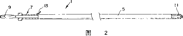
Fig. 2 is the side view of the disconnection of sensing system shown in Figure 1, and wherein pick off stretches out from skirt;
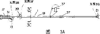
Fig. 3 A is the detailed diagrammatic sketch of the preferred embodiment of inserted link in accordance with the principles of the present invention, Fig. 3 B is the guide wire of alternative shape of inserted link shown in Fig. 3 A, Fig. 3 C cuts open the cutaway view of getting along the line 3C-3C among Fig. 3 A, Fig. 3 D is the end view of the inserted link seen from the handle end of Fig. 3 A, Fig. 3 E is the partial view of the handle portion of inserted link, Fig. 3 F is the zoomed-in view of Fig. 3 A, show the details of slope shape lug, Fig. 3 G is the zoomed-in view of inserted link end, show the details of applicator, Fig. 3 H is the end view of the inserted link seen from the applicator end, and Fig. 3 I cuts open the cutaway view of getting along the line 3I-3I among Fig. 3 H;
Fig. 4 is the exploded perspective view that circuit connector, spiral hollow needle and cup are shown;
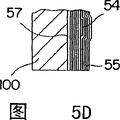
Fig. 5 A-5C is the detailed diagrammatic sketch of a specific embodiment of circuit connector, and Fig. 5 D cuts open the cutaway view of getting along the line 5D-5D among Fig. 5 C;
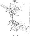
Fig. 6 one is used for sensing system is connected in the axonometric chart of the adapter of diagnostic device;
Fig. 7 A-7D shows the cup section of pick off, and Fig. 7 E cuts open the cutaway view of getting along the line 7E-7E among Fig. 7 D;
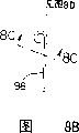
Fig. 8 A is the vertical view of the pin part of pick off, Fig. 8 B is that pin is at " J " side view of shape fabrication stage, Fig. 8 C cuts open the cutaway view of getting along the line 8C-8C among Fig. 8 B, Fig. 8 D is that pin is at " P " vertical view of shape fabrication stage, Fig. 8 E and 8F are the zoomed-in views that the window portion details of pin is shown, and Fig. 8 G shows " O " shape fabrication stage of pin;
Fig. 9 A and 9B are respectively the axonometric charts of the disconnection of light emitting diode (LED) circuit and photo detector circuit in accordance with the principles of the present invention;
Figure 10 is the block diagram according to optical measuring device of the present invention, as to utilize wave spectrum;
Figure 11 is the block diagram according to a control unit of the present invention and optical generator;
Figure 12 is the timing block diagram by the multichannel wavelength signals of the generation of the device among Figure 11;
Figure 13 is the block diagram according to optical measuring device of the present invention, as to utilize a plurality of light paths;
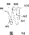
Figure 14 is the side view of spiral type pin according to another embodiment of the present invention;
Figure 15 is the axonometric chart that utilizes the probe of spiral type pin shown in Figure 14;
Figure 16 is the sketch map of sensing system in accordance with another embodiment of the present invention;
Figure 17 is the sketch map that the interface of sensor diagnostic and recognition function can be provided.
Preferred forms of the present invention
To describe each member and the assemble method of the fetus pulsation blood oxygen transducer system of preferred embodiment below in detail according to the present invention.Specialized spare part and their assembling procedure below with reference to this sensing system are set forth various aspects of the present invention.Fig. 2 and Fig. 3 are the views of sensing system 1 in accordance with the principles of the present invention.Sensing system 1 comprises a skirt 5, an inserted link 7, a circuit connector 9 and a pick off 11.To describe each member and relevant assembling procedure of sensing system 1 in the literary composition in detail.
I. skirt
II. inserted link
Fig. 3 A is the detailed diagrammatic sketch of a preferred embodiment of inserted link 7 in accordance with the principles of the present invention.Generally speaking, inserted link 7 comprises one handle 17, a bar portion 19 and an applicator 21, will describe each part in detail herein.Inserted link is preferably used biocompatible plastic material, and the AMOCO7234 that for example has 2% omnicolor is shaped integratedly.Yet the various piece of inserted link 7 also can separately form, and makes of other material of for example metal or timber and so on.
A. handle
1. lug
See also Fig. 1,2 and 3B, on inserted link 7, be provided with a lug 13, as shown in Figure 1, when an end of lug 13 being inserted skirt 5 terminal, can prevent that pick off 11 from stretching out from the end of skirt 5.This feature can be for pick off 11 provides protection in transportation, and in that the time spent can not be kept at pick off 11 in the hard relatively skirt 5.Pick off 11 is kept at the probability that can also make pick off 11 cut or tear its sterilization storage bag in the skirt 5 reduces to minimum.Another advantage that pick off 11 is kept in the skirt 5 is when pick off 11 is introduced patient's intravaginal, to have more safety and comfortableness.Pick off 11 is kept at the probability that also makes patient be stabbed or hurt by pick off in the skirt 5 reduces to minimum.When lug 13 was inserted the near-end of skirt 5, pick off 11 stretched out from the end of skirt 5, as shown in Figure 2.
According to the present invention, when inserted link 7 was inserted patient's vagina, inserted link remained in the skirt 5.After skirt 5 inserts fully, inserted link 7 is extracted out from skirt 5 slightly, so that allow lug 3 throw off, promptly deviate from from skirt 5 as shown in Figure 2.Subsequently, inserted link 7 can be moved back in the skirt 5, perhaps under the situation of inserted link 7 maintenance original positions, twitch skirt 5 slightly, so that pick off 11 stretches out from the end of skirt.Subsequently, fetus is located and be attached to pick off 11.
According to the present invention, lug 13 should have enough elasticity, and when being in the skirt 5 with the end of convenient lug 13, the end of lug 13 can outwards be suppressed from inserted link 7, uses the lip of cleaning skirt 5.So when inserted link 7 was retracted skirt 5, lug can impede motion.The advantage of this feature is, lug is thrown off, and needn't lug 13 be shifted out passage with hands.
Shown in Fig. 3 B, this figure is the zoomed-in view of lug 13, and lug 13 is arranged on that end of close bar portion 19 of handle 17.Lug 13 comprises one first shank 25, one second shank 27 and one the 3rd shank 29.Second shank 27 roughly becomes 90 ° with respect to first shank 25, and the 3rd shank 29 roughly becomes 90 ° and from its terminal outwards bending with respect to second shank 27.
The inner-diameter portion whose of skirt 5 can be admitted bar portion 19 and the 3rd shank 29.When shank 29 was filled in skirt 5, second shank 27 can stop that away from the inner-diameter portion whose of skirt 5 inserted link 7 further inserts skirt 5.The length of first shank 25 is decided according to the length of inserted link 7 and skirt 5, is enough to prevent that pick off from stretching out from the end of skirt 5.For example, if the length that the skirt 5 of pick off 11 is installed slightly is shorter than the length overall of bar portion 19 and applicator 21, then skirt 5 will stretch out in the pin portion of pick off 11, so the length of first shank 25 should at least slightly be longer than the length that the pin portion of pick off 11 stretches out from the end of skirt 5.
Shown in Fig. 3 B, lug 13 comprises an abdominal part 23, and when lug 13 was filled in skirt 5, this abdominal part did not enter skirt, promptly as a stop part.Preferably shown in Fig. 3 B, the height of abdominal part 23 is identical with second shank 27.Yet abdominal part 23 also can be shorter or long than second shank 27, as long as it can stop that inserted link further inserts skirt 5.When the 3rd shank 29 was filled in skirt 5, the length overall of first shank 25 and abdominal part 23 should be enough to prevent that pick off 11 from stretching out from the end of skirt 5.
2. the line of rabbet joint
Preferably shown in Fig. 3 C, handle 17 comprises the line of rabbet joint 31 of a receivability circuit connector 9.Fig. 3 C cuts open the cutaway view of getting along the line 3C-3C among Fig. 3 A.Fig. 3 D is the end view of the inserted link 7 seen from handle 17 those ends.Shown in Fig. 3 A, 3C and 3D, the line of rabbet joint 31 extends along the whole length direction of handle 17.The width of the line of rabbet joint 31 is slightly larger than the width of circuit connector 9 at least, so that admit circuit connector 9.When turning handle 17 so that pick off 11 is attached to fetus, circuit connector 9 is positioned in the line of rabbet joint 31, and for example pushes down this line of rabbet joint by user with thumb and be held in place.Under this mode, circuit connector 9 and inserted link 7 can rotate together, thereby prevent that circuit connector 9 is distorted in skirt 5.
3. hollow end
Preferably shown in Fig. 3 D, handle 17 comprises that one is axially extended hollow parts or cavity 33 along its longitudinal axis roughly.The size of cavity 33 and structure make its interface end that can hold circuit connector 9, i.e. near-end.Shown in Fig. 1-2, for the ease of transportation, the interface end of circuit connector 9 by around and insert cavity 33.Preferably, the width of cavity 33 diminishes gradually along its length direction, therefore, gently the interface end of circuit connector 9 is inserted cavity 33 can cause circuit connector 9 the interface end wedging enter cavity 33, use that circuit connector 9 is held in place.
In the embodiment shown, cavity 33 is roughly rectangle, and it has one near the plane of the line of rabbet joint 30 and a semicircle opening relative with the line of rabbet joint 31.Yet other shape also is possible, as long as the width of cavity is slightly larger than the width of the interface end of circuit connector 9 at least.For example, cavity 33 can be orthogonal fully, and its size is slightly larger than the corresponding size of the interface end of circuit connector 9.
Shown in Fig. 3 C and shown in the 3E, several fins 35 are arranged, on the outer surface of handle 17 so that grip.When pick off 11 was attached to fetus, fin 35 can improve the ability that user rotates inserted link 7.
B. bar portion
1. protruding
2. slope shape lug
As shown in Figure 3A, bar portion 19 comprises a lug 39, and it is slope shape preferably, is on the not far position of handle, and departs from 180 degree with respect to lug 13.See also Fig. 3 F.Lug 39 can be lug 13 opposite force is provided, and when lug 13 was inserted skirt 5, this opposite force can increase the tension force that inserted link 7 is held in place.The height of lug 39 measures from the central axis of bar portion 19, should be slightly larger than the inside radius of skirt 5 at least, but less than the interior diameter of inlet tube 5.For example the height of lug 39 preferably 0.1 inch add 0.0625 inch (from Fig. 3 C, be half of 0.125 inch of diameter of bar portion 19), promptly the total height that measures from the central axis of bar portion 19 is about 0.163 inch, and the inside radius of skirt 5 is about 0.123 inch (half of the interior diameter 0.246 of inlet tube 5).Therefore, when barre portion 19 inserted skirts 5, lug 39 contacted with the inner surface of skirt 5, and with this part of bar portion 19 from contacting points position off-center slightly, therefore, when lug 13 is filled in skirt 5, can inserted link 7 be held in place by opposite power.Preferably, lug 39 is slope shapes, tilts gradually towards the applicator place end of bar portion 19, makes lug 39 can not hinder inserted link 7 to insert skirts 5.
C. applicator
Inserted link 7 comprises an applicator 21, and it can be used for keeping pick off 11, throws off up to pick off 11 and inserted link 7.See also Fig. 3 G-3I, applicator has several features, can allow its (1) to keep pick off firmly; (2) when pick off 11 is attached to fetus; force moment protection can be provided, and (3) pick off 11 is attached finish after, can be drawn back easily.
1. hex shape
Shown in Fig. 3 H, applicator 21 comprises that can form one is the wall 41 of hex-shaped openings 43 substantially, and described opening can match for hexagonal bottom with the basic of pick off 11.Hex shape can provide inserted link 7 (socket) to connect with the socket/nut type of pick off 11 (nut).Therefore, when pick off 11 is attached to fetus,, has only seldom or do not have any slip as long as rotate just rotation sensor 11 reliably of inserted link 7.
2. be used to connect the groove of joining pick off " projection "
In order to prevent that inserted link 7 from undesirable disengagement taking place, and was provided with groove 47, so that connect the projection (will be described in more detail below) on the base plane of joining the pick off 11 that is roughly hex shape on the inner surface of wall 41 before pick off 11 is attached fully.In the embodiment shown in Fig. 3 I, on the whole inner peripheral surface of applicator 21, be provided with groove 45, the part of this groove in the middle part of each face of wall 41 slightly is wider than the part at its edge.
3. cross force moment protection
After pick off was attached to fetus reliably, the tissue that can cause on the attachment points that is rotated further of pick off 11 caused damage.Sensing system of the present invention provides several features of " crossing force moment protection ", also is rotated further after the secure fixation at pick off to prevent pick off 11.
For this reason, the hexagonal shape that is roughly of applicator 21 is divided into three parts by groove 45.Groove 45 can provide force moment protection; promptly; allow wall 41 outside deflections; thereby when moment has surpassed predetermined torque in the pick off insertion process (just when inserted link 7 at pick off 11 correctly attached or stopped operating after when still continuing to rotate), slide with respect to the wall of applicator 21 in the bottom that makes pick off.Shown in Fig. 3 H, the wall 41 of applicator 21 has formed six faces, is just disconnected by groove 45 every a face.Except can be for pick off 11 provided the force moment protection, the hex shape of groove 45 can provide a kind of and hear and/or touch the expression pick off that the obtains indicant of secure attachment.If inserted link 7 also continues to rotate after pick off 11 secure attachment; wall 41 deflection before this thinks that pick off 11 provided force moment protection, and then, pick off 11 slides in applicator 21; because 7 of inserted links are reorientated in sensor base, wall 41 engages again and puts in place.This slip and reorientating can produce one can audible engaging sound and/or vibration, and/or is felt by user, thereby the expression pick off is fastening fully.
III. circuit connector
Fig. 4 is the axonometric chart of the disconnection of circuit connector 9.Fig. 4 also shows a hollow spiral needle 65 and a cup 67, and they have formed the part of pick off 11, and this will be described in more detail below.Fig. 5 A-5D shows the details that comprises its size of circuit connector 9.As shown in Figure 4, circuit connector 9 has an interface end 49, a sensor side 51 and an interconnect portion 53, interconnect portion 53 makes signal be sent to interface end 49 by conductor 54 from sensor side 51, the minimum widith of conductor 54 is 0.010 inch, the minimum interval is 0.010 inch, and the distance of periphery is 0.02 inch outside the conductor of ragged edge and the circuit connector.Sensor side 51 comprises a plurality of contact areas (contact pad) 100, and they generally are that the thickness that covers on the nickel dam is the Gold plated Layer of 25 μ.
A. reduce the artefact of motion
1. circuit board is near the narrower width of pick off cup
As shown in Figure 4, the width of that part 132 of the close sensor side 51 of circuit connector 9 is narrower than part adjacent thereto 134, thereby has improved near the flexibility the sensor side 51, thereby reduces the artefact of motion.In other words, the a small amount of adverse effect that move of pick off 11 on circuit connector 9 can be reduced to minimum, this is because bending easily of the narrower part of the close sensor side 51 of circuit connector 9 and distortion can not make this bending and distortion apply along the whole length direction of circuit connector 9.
2. along the joint-cutting of circuit board length direction
Length direction along circuit connector 9 is provided with the conductor 54 that preferably is made of copper.The present invention also has such design,, shown in Fig. 5 A and 5B, between some or all conductor 54 and along the length direction of circuit connector or the part of length direction several slits (not shown) is set that is.These longitudinally slit can improve the flexibility of circuit connector, use the artefact that reduces to move.
B. reduce noise
1. make the circuit shielding
Shown in Fig. 5 C and 5D,, on the both sides of conductor 54, be provided with silver- colored screen layer 55 and 57 along a part of length of circuit connector 9. Screen layer 55 and 57 has covered the width of circuit connector 9, and interconnects by the hole on the interface end 49 59.The diameter in hole 59 generally is 0.030 inch, has wherein filled up silver-colored black epoxy resin so that screen layer 55 and 57 is coupled together.Screen layer 55 and 57 can make circuit exempt from extraneous electrical Interference, and the internal electric between the signal that transmits on the conductor 54 disturbs.Therefore, screen layer 55 and 57 can reduce the noise in the sensing system, and improves its precision.
2. to the differential driving of LED
In one embodiment of the invention, conceived each LED in the pick off 11 has been carried out differential driving, used making the signal pulse that in pair of conductors, offers LED equal and reverse.LED is carried out differential driving can improve low-noise performance, and owing to the signal on two circuits trends towards cancelling each other out, thereby can allow on circuit connector 9, to arrange conductor 54 very close.Adopt differential driving can also improve safety.
C. near the exposure conductor pick off
Be provided with the conductor 61 of an exposure in the sensor side 51 of circuit sensor 9, when pick off 11 was attached to fetus, this conductor can serve as the reference electrode that contacts with mother's health (normally inner).Shown in Fig. 5 A, reference electrode 5A preferably exposes about 1.0 inches, but also can adopt longer slightly or shorter length of exposure.An exposed electrodes is set on circuit connector, rather than as conventional apparatus, is arranged on the pick off 11, can make the size minimum of pick off, make reference electrode and mother have the good probability maximum that contacts simultaneously.In addition, long exposed electrode being set can make at least a portion of reference electrode 61 and mother form excellent contact.
D. interface end
The interface end 49 of circuit connector 9 comprises contact area 63a-63g, so that with simply a kind of and mode connection diagnostic equipment (not shown) cheaply.For example, circuit connector 9 can be connected to diagnostic device easily by interface connector 10 as shown in Figure 6.
IV. interface connector
As shown in Figure 6, interface connector 10 comprises a housing 40 of being made up of upper casing 40a and lower casing 40b.Preferably, upper casing 40a is fixed in lower casing 40b by the mode of gluing or ultrasonic bonding.Yet, also can adopt other method to fix two and half shells, for example screw is fixed.One snapper 42 preferably is attached to upper casing 40a by means such as gluing or ultrasonic bonding.Snapper 42 can be fixed on adapter 10 near the patient in the use of sensing system.For example, one can be had and meet the belt of joining snapper thigh portion, so that the snapper 42 of adapter 10 is buckled into the snapper that matches around mother.Perhaps, adapter 10 can comprise a clip 66, is used for adapter 10 is connected in being on the patient body or near position eaily.For example, clip 66 is slided on a belt of mother's thigh portion and (for example do not connect and join snapper).
Formed opening entered housing 40 when cable 44 mutually combined by upper casing 40a and lower casing 40b.Preferably, cable 44 have electric wire 46 appear the end near release of tension lug 48.Release of tension lug 48 is in the assembling housing 40 afterwards, thereby the stress on the cable 44 can not put on electric wire 46.Electric wire 46 can comprise an earth lead, and it is fixed in housing by the screw 50 that a spiral is matched with in the threaded insert 52.Preferably, earth lead can be connected for screen layer 55 and 57 provides a ground connection.
Yet, end cap 60 also can be bonding or supersonic welding be connected to housing 40.Perhaps, housing 40 can not have end cap, makes sealing member 64 remain on appropriate location in the housing 40.
Best, the interface end 49 of circuit connector 9 remains on the appropriate location by conductive contact piece 58a-58g and sealing member 64 by frictional force.Yet, the mechanism such as snap fit assembly or pin can be set on interface end 49 and/or adapter 10, remain on the appropriate location with interface end 49 with circuit connector 9.
V. pick off
As shown in Figure 4 and the above, pick off 11 has the helical form pin 65 and a cup 67 of a hollow.In an illustrated embodiment, pin 65 has a circuit of LED 69 and a photo detector circuit 71.Signal offers circuit of LED 69 and produces light, and light is propagated by patient and by photo detector circuit 71 and received.The signal of the light that expression is received is back to the diagnostic equipment by circuit connector 9 from photo detector circuit 71.The details and the size thereof of the cup 67 of a preferred embodiment of the present invention are shown among Fig. 7 A-7E.The details and the size thereof of the pin 65 of a preferred embodiment of the present invention are shown among Fig. 8 A-8L.Be understood that the function of sending and receive light from pin can realize by optical fiber, light source and photodetector be arranged on the position of pin outside.
A. cup
1. hexagon pedestal
2. the blunt rounded edge that was used for force moment protection
As mentioned above, after pick off 11 firmly was connected in the baby, rotation sensor may cause tissue injury in the junction continuously.For force moment protection was provided, for example the edge 75 of pedestal 73 can be rounded to the fillet with about 0.022 inch radius, shown in Fig. 7 C.When applying excessive moment of torsion on the cup 67, blunt rounded edge 75 allows pedestal 73 " cunning " to go into applicator 21, and this normally firmly connects the back at pick off 11 and takes place.
3. be used for cup is remained in the lobe of applicator
Shown in Fig. 4 and 7A-7D, has projection 77 on the apparent surface of pedestal 73.Projection 77 engages with groove 47 when pedestal 73 inserts applicator 21, pulls out pick off 11 accidentally to help prevent inserted link 7 before pick off 11 fully is connected in the baby.Projection 77 can increase makes inserted link separate required " pulling out " power with pick off 11.Best, optimize this pullout forces, to avoid tissue injury to the baby, keep pick off 11 to engage simultaneously with the baby, when being on one's body appropriate location of baby, pick off and pick off 11 allow pick off 11 to separate and in the patient body, take out, leave with skirt 5 with applicator 21 at inserted link 7.
4. be used to keep the Assembly part of pin
5. be used to admit the opening of circuit connector
B. pin
As shown in Figure 4, pin 65 holds circuit of LED 69 and photo detector circuit 71, and has several help pick offs 11 to keep being connected in patient and significantly do not increase tissue injury and the part that applies moment of torsion and significantly do not increase the taking-up resistance.With reference to Fig. 8 A-8G pin 65 is described in detail.Pin 65 formed in several different stages, was called " J " stage, " P " stage and " O " stage, carried out different programs in each stage.With these stages (also will be described) can guarantee effectively, manufacturing needles 65 reliably, and make percent defective lower.
1. lobe
Referring to Fig. 8 A, pin 65 preferably has lobe 83 and 85, a light-emitting diode window 87 and a photoelectric detector window 89.Lobe 83 is formed in light-emitting diode window 87 zones, and lobe 85 is formed in light-emitting diode window 89 zones.For example, can come slightly excessively to fill up light emitting diode and photoelectric detector window 87 and 89 with a transparent encapsulation material, thereby form lobe 83 and 85, they help pin is remained on the appropriate location, and can significantly not increase tissue injury, apply moment of torsion or take out resistance.Pin 65 preferably has two lobe that are formed on the spiral inner surface.But, also can use the lobe of varying number and diverse location.And, also can use other method to form lobe.For example, on the outer surface of spiral, form an one lobe.Lobe can form to cause the material projection by needle material being carried out machined.
2. " J " stage
It is a pipe fitting that pin 65 begins, and preferably the tubing that is precuted by length forms, and its internal diameter is about 0.19 inch, and external diameter is about 0.3 inch, and length is about 1.13 inches.The material of pipe 91 is the stainless high rigidity hypodermic needle tube of 211/2RW304 preferably.Also can adopt other size and material, but preferably adopt the tubing of relatively large specification according to the present invention, so as pin 65 better, more reliable, repeatability more is arranged in tissue in the highland.Use an axle that pipe is formed spiral type.Yet as mentioned above, this shaping occurs in the different stages." J " stage comprises tubing formation " J " shape pin.
Utilize an axle that is fixed in the vice, an end of tubing is sandwiched on the axle.Push down the top of tubing with an aluminium sheet, mandrel and make tubing rotate 180 ° simultaneously, thereby form " J " shape pin.Then, can remove clip, and " J " shape pin is taken off from axle.
3. multiaspect is cut sth. askew
Form the tip 95 of pin 65 by the multiaspect operation of cutting sth. askew, with acutance and the intensity of guaranteeing pin.This operation of cutting sth. askew preferably includes at least three facets of formation.First facet 92 is shown among Fig. 8 C, and second facet 94 and the 3rd facet 96 are shown among Fig. 8 D.Each facet can form by wearing into required all angles by hand with most advanced and sophisticated 95.Best, as described below, use pin to keep anchor clamps and clamp to form first and second facets, and form the 3rd facet by hand grinding at predetermined stop position.
A. first facet
As shown in Fig. 8 C, the plane that first facet 92 is cut into respect to the close needle point 95 of helix becomes 15 ° approximately.The first facet clamp comprises that one keeps anchor clamps, and its shape is made and pin can be firmly held in place, so that pin is formed required shape.In another embodiment of the present invention, other facet is further cut sth. askew in facet 92, to improve the intensity at pin 65 tips.For example, the tip part of facet 92 can be 30 ° of angles, is 20 ° of angles then, is 15 ° of angles that form facet 92 remainders at last.
" J " shape pin 93 is placed the maintenance anchor clamps of the first facet clamp.One atomizing device is set in whole grinding process, all the time " J " shape pin and emery wheel are sprayed.Preset keeping anchor clamps with a block with the required amount of cutting sth. askew.One Dremel motor is opened to enough speed, and " J " shape pin is ground at leisure the point of the block of running on the anchor clamps.Any burr on the inclined-plane can wait with guarded blade utility knife, razor or file and remove.
B. second facet
" J " shape pin that will have first facet 92 places the maintenance anchor clamps of the second facet device, these anchor clamps to have a block that is used for required stock removal.With the Dremel tool settings is to be lower than speed 1 at full speed, and opens.Emery wheel is resisted against " J " shape pin and grinding " J " pin in the position as second facet 94, runs into block up to it.
C. the 3rd facet
Maintain " J " shape pin with pliers or tweezers at the contact place of crooked and straight position with first and second facets 92 and 94.Use a for example Dremel instrument, and preferably use fine grinding wheel, grinding the 3rd facet 96 on the curved end of the inboard of pin if desired, is repaired first facet 92 and second facet 94.The inclined-plane preferably is about 0.100 inch ± 0.010 inch.
4. " P " stage
" P " stage comprises with " J " shape pin formation " P " shape pin 98, shown in Fig. 8 B.Utilize the axle in the vice, " J " pin is sandwiched on the axle with clip.Clip should not be set directly on most advanced and sophisticated 95.Push down the straight part of " J " shape pin with aluminium sheet, mandrel makes " J " shape pin turn over 90 ° simultaneously, forms " P " shape pins 98 from two.Afterwards, can remove clip, and " P " shape pin is taken off from axle.
5. window forms
Shown in Fig. 8 D, pin is formed with light-emitting diode window 87 and photoelectric detector window 89.Photoelectric detector window 89 best as close as possible beveled end in pin 65 (tip), the center of light-emitting diode window 87 are also preferably as close as possible in the beveled end of pin 65, and direct sight line still is provided between two windows simultaneously.Preferably make window be positioned as close to beveled end in pin, even to guarantee that pin does not insert in the patient body fully, light also can be propagated between two windows.In a preferred embodiment of the present invention, about 130 ° ± 10 ° of the misalignments of light-emitting diode window 87 in the center of photoelectric detector 89.The details of photoelectric detector window 89 and light-emitting diode window 87 is shown in respectively among Fig. 8 E and the 8F.In a preferred embodiment of the present invention, window 87 and 89 is to be formed in the pin by grinding off needle material.But, also can use other method, comprise chemical etching.
For forming window 87 and 89, keep anchor clamps to place the bottom position of grinding attachment on one pin, make anchor clamps towards tilting.A bar of anchor clamps is forwarded to upper/lower positions, and unclamp clip.One mineral oil atomizing device is set, so that " P " shape pin 98 and end mill(ing) cutter are sprayed.One microscope preferably is set observes the pin wall.
Keep in the anchor clamps two possible pin positions being arranged at pin." P " shape pin 98 should be arranged in the anchor clamps, makes the non-beveled end point operation personnel of pin." P " shape pin 98 must be shelved on the prelocalization pin.In case behind the location, available thumbscrew is gone into anchor clamps with the pin clamping.Thumbscrew snugly should be tightened, be begun the mineral oil spraying then.Then, open servomotor, and put down end mill(ing) cutter.In case after putting down end mill(ing) cutter, the bar on the anchor clamps is mentioned the full scale position, thereby cuts out window 89.After cutting out window 89, mention end mill(ing) cutter, unclamp the pin folder, take off pin.Window 89 should be cut on the inboard of about 0.010 to the 0.015 inch spiral type camber line of distance inclined-plane end, shown in Fig. 8 G.The most handy sales volume rule or microscope reticle come measurement size.
The cutting process of light-emitting diode window 87 is similar to the cutting process of above-mentioned photoelectric detector window 89.Yet pin is in a different position in milling process.For cutting out light-emitting diode window 87, " P " shape pin 98 is placed anchor clamps, the non-beveled end that makes pin is operator dorsad.As mentioned above with shown in Fig. 8 D, the center of light-emitting diode window 87 should be apart from the center of photoelectric detector window 89 about 130 °.The most handy sales volume rule or reticle come measurement size, and take measurement of an angle with protractor or angle reticle.
6. deburring and cleaning
In the process of preparing last assembling, preferably " P " shape pin 98 is carried out deburring and cleaning.Use a shaver blade to rebuild all big burrs of the surperficial upper process of window 87 and 89.Check tail end (non-cutting sth. askew), open with the end of guaranteeing pin.If the end is stopped up or be jagged, then remove the burr of this end with the tip of blade.Remove burr with Foredom rig and thick diamond bit from the inboard and the outside of window.Preferably remove all burrs.
Then, " P " shape pin 98 behind the removal burr is put into the ultrasound wave cleaner, in little cleaning solution of distilled water and 2%, cleaned about 30 minutes.Afterwards, take out " P " shape pin 98, and replace solution in the ultrasonic washing unit with 100% distilled water.Once more " P " shape pin 98 is put into ultrasonic washing unit and cleaned taking-up after about 15 minutes, blow " P " shape pin 98 with compressed air.
Advise with microscope reticle and/or sales volume and to measure all critical sizes, comprise angle, window 87 and the angle between 89 the center and the length and the width of photoelectric detector window 89 and light emitting diode 87 of first facet.The width of light-emitting diode window 87 and photoelectric detector window 89 should be between about 0.0170 inch to 0.0210 inch.The length of photoelectric detector window 89 should be about 0.068 inch, and the length of light-emitting diode window 87 should be about 0.050 inch.After being preferably in cleaning, check that " P " shape pin has or not any damage or residual burr.So-called critical size is determined according to employed part, material and circuit in the preferred embodiment.Be understood that other part, material or circuit are selected to need different " key " sizes.
Fig. 8 A and 8G show the preferred dimensions of pin 65, and they comprise about 0.190 inch total external diameter and about 0.170 inch total depth.Shown in Fig. 8 G, helix preferably has about 0.063 inch pitch, and spirals with about 22 ° angle.Will discuss as the final assembling of following reference, the last coiling of pin carries out after being preferably in circuit of LED 67 and photo detector circuit 71 insertion pins.
C. sensor circuit
Fig. 9 A and 9B are respectively the axonometric charts of circuit of LED 69 and photo detector circuit 71.Shown in Fig. 9 B, photo detector circuit 71 has photodiode small pieces 97 that are installed on the flexible PCB 99.Article one, connecting line 101 is connected in a plate 103 on the flexible PCB 99 with a plate on photodiode small pieces 97 1 sides.The opposite side of photodiode small pieces 97 is directly connected in a sheet of connecting plate 105 on the flexible PCB 99.A kind of suitable photodiode small pieces 97 are 5538A800 products that the silicon sensor limited company by Wisconsin, USA Dodgeville provides.
Circuit of LED 67 has two LED wafers 107 and 109 that are installed on the flexible PCB 111.Referring to Fig. 9 A, connecting line 113 is connected in a plate 115 on the flexible PCB 111 with a plate on first LED wafer, 107 1 sides.Article one, connecting line 117 is connected in second LED wafer 109 with first LED wafer 107.Two LED wafers 107 and 109 opposite sides are directly connected in a sheet of connecting plate 119 on the flexible PCB 111.In Fig. 9 A, LED wafer 107 is shown and is higher than LED wafer 109.But LED wafer 107 can change because of the different of manufacturer with 109 actual height.LED wafer 107 preferably can produce the light that wavelength is about 730 nanometers.A kind of first suitable LED wafer 107 is MC-RIN-DD730/5 products that the SANLING cable U.S. limited company by New York, United States New York provides.Light emitting diode 109 preferably can produce the light that wavelength is about 940 nanometers.A kind of second suitable light emitting diode 109 is ED-012IRA products that the SANLING cable U.S. limited company by New York, United States New York provides.Connecting line 101,113 is connected with 117 usefulness Shinkawa ultrasound wave wedge bonders.
In a preferred embodiment of the present invention, flexible PCB 99 and 111 have the about 0.0010 inch thick polyamide of one deck, about 0.0010 inch thick tack coat, the about 0.0007 inch thick copper of one deck (being equivalent to conductor), another layer about 0.0005 inch thick and roughly meet the tack coat of copper layer shape and another layer about 0.0010 inch thick and roughly meet the polyamide of last tack coat shape.
1. circuit is penetrated pin
According to the present invention, circuit of LED 69 and photodiode circuit 71 penetrate pin 55 by the following mode that will describe in detail, and the probability that this mode can make circuit damage is reduced to bottom line.Specifically, because photoelectric detector window 89 is close to the beveled end of pin 65 most, thereby photo detector circuit 71 penetrated pin 65 before circuit of LED 69.The most handy microscope is observed this program.
" P " shape pin 98 remains in pin and keeps with tweezers photo detector circuit 71 being penetrated photoelectric detector window 89 simultaneously in the anchor clamps.Expose the non-beveled end of " P " shape pin 98 at photo detector circuit 69 after, can catch and spur circuit 71 and connecting line 105 is positioned near the window 89.Utilize a side of tweezers,, photodiode circuit is inserted window 89 by photodiode small pieces 97 being pressed onto near the connecting line 105.Then, with the other end of tweezers the back of photodiode small pieces 97 is pushed forward into window 89.This can make photo detector circuit 69 to falling into window, and can not damage connecting line 105.Because connecting line may rupture, thereby should directly not push it.The top of care should be used to ground pushing photodiode small pieces 97 is because its also fracture easily.Be preferably in circuit 71 and fall into after the window, catch the end and make photodiode small pieces 97 be positioned at the center of window 89 with it.Afterwards, keep photodiode small pieces 97 to be resisted against the bottom of pin, between the wall of photodiode small pieces 96 and " P " shape pin 98, apply a ultraviolet radiation binding agent Dymax 1-20280 simultaneously.Keeping photodiode small pieces 97 in the appropriate location, using uviol lamp and make 5 seconds of this adhesive cures.Then, whether conducting and short circuit of testing needle.Next, with identical program circuit of LED 67 is penetrated " P " shape pin 98, what just light emitting diode penetrated is light-emitting diode window 87.
" P " shape pin is wound into final form, i.e. " O " (spiral) shape pin 65 is shown in Fig. 4,8A and 8G.This by with " P " shape pin through locating to clamp pin and realize for about 300 ° on the axle and in the distance beveled end.Light-emitting diode window 87 can be guaranteed neither can clamp like this and also the photoelectric detector window can be do not clamped.Then, the beveled end that axle is orientated to make " P " shape pin up.An aluminium sheet is remained on the top of axle, and mandrel and pin is reeled thereon, thereby " O " shape pin 65 formed.Finish the full circle of pin 65 ends with pliers, making does not have straight part.Should avoid with excessive power, because may make pin 65 distortion like this and/or cut off circuit 69 and 71.Best, behind last coiling, pin 65 final " O " shapes 2 whole circles of just reeling.
VI. final assembling
After each above-mentioned subassembly was finished, sensing system 1 just can supply final assembling.At first, circuit connector 9 is connected in cup 67.Cup 67 is placed final assembling jig, opening 81 is alignd with the plane surface of anchor clamps.The sensor end 51 of circuit connector 9 is slipped into cup 67 by opening 81, make conductive plate up.Circuit connector 9 is arranged in it is shifted out perpendicular to cup 67.Sensor end 51 rises in the cup 67, and small amount of ultraviolet radiation binding agent Loctite 3321 is placed on the bottom surface of cup 67.Then, sensor end 51 is pressed onto on the binding agent, clamps downwards securely, make adhesive cures with uviol lamp simultaneously with tweezers.
Then,, make photodiode circuit 71 be arranged in left side (being the 6:00 position of Fig. 4), thereby pin 65 is snapped in cup 67, the end of circuit 69 and 71 is arranged in the cup, and conductor up by the opening in cup 67 tops.Counterclockwise rotate pin 65 (but still its engaging not being put in place) with tweezers, in Fig. 4, be positioned at about 11:00 position up to the non-beveled end of pin 65.Afterwards, clamp pin 65, pin is pushed cup 67, snap in groove 79 up to it with tweezers.
Next, between circuit connector 9 and light emitting diode and photo detector circuit 69 and 71, be electrically connected.Because the end that photo detector circuit 71 should be longer than in the end of light emitting diode 69, thereby light emitting diode 67 and photo detector circuit 71 can be distinguished.Photo detector circuit 71 (afterbody is shorter) should be arranged on from the right side of circuit connector 9 between third and fourth conductor.Circuit of LED 69 (afterbody is longer) should be arranged between the conductor of two rightmost sides of circuit connector 9.Then, should be in coating ultraviolet radiation binding agent Dymax 1-20280 on two circuit 69 and 71, circuit 69 and 71 is centered on the circuit connector plate and is fixed on the appropriate location by end and bottom at big connecting plate.Subsequently, with a sharp razor tip circuit 69 and 71 is cut into length in the cup 67.Should be in the bonding part (being the whole length of the plate) pin of firmly swiping, to guarantee good bonding and lower resistance.Bond to form conduction with guarded blade utility knife coated with conductive binding agent Acheson 5915.Conductive adhesive should have been placed a period of time, to guarantee that higher viscosity is arranged.Form four conductive bond: circuit 69 and 71 conductor and the big connecting plate of adjacent circuit adapter 9 respectively have one.The part of being swiped of pin 65 is bonded in big connecting plate conductively in 9:00 shown in Figure 7 position.Should be along a large amount of coated with conductive binding agents of the whole length of connecting plate.Then, under about 150 ℃ the pick off 11 that assembles and circuit connector 9 being carried out baker solidified about 20 minutes.Best, before the final encapsulation of pick off, the electric property of pick off is tested.
If pick off 11 then can carry out final encapsulation by electric test.With a syringe or an EFD allotter coated with adhesive Dymax 1-20280, cup is encapsulated.With an applicator pin adhesive coated is arrived the appropriate location.Cup fill with its 3/4, guaranteeing does not have the air gap, is cured with uviol lamp then.Pin should fully be covered 12:00 position at least, and is no more than the 10:00 position.Then, with an applicator pin binding agent Dymax 1-20280 is applied into the inclined-plane, it is flat to be annotated limit and limit up to it.As discussed above, each window 87,89 encapsulates by coated with adhesive Dymax 1-20280, up to window spill-over slightly.Next, with two or three 5 seconds sections binding agent being carried out ultra violet lamp solidifies.One more shallow adhesive layer Loctite 3321 is set on the bottom of circuit connector 9, seals to enter the cup place at it, and be cured with uviol lamp.Circuit connector 9 is pulled down, it is lain low along the cup wall.Gap between circuit connector 9 and the cup groove 81 is filled, and solidifies through ultra violet lamp.This process should make circuit connector 9 and binding agent flush with cup.Final encapsulation preferably should not make the external diameter of cup increase.The reply window checks, guaranteeing no coarse part in the window, and light emitting diode and connecting line can to pass through window visible.
Before inserted link 7 was inserted skirt 5, pick off 11 should be oriented to and make circuit connector 9 on the sidepiece of inserted link 7, and groove 31 is in the sidepiece of handle 17.After pick off is located like this, interface end 49 is inserted the hollow end 33 of handles 17.Next, holding circuit adapter 9 makes it be arranged in the groove along handle 17 against inserted link 7.When circuit connector 9 is remained on the appropriate location, inserted link 7 (together with the pick off 11 that is connected in it) is slipped into skirt 5.But when inserted link 7 almost completely inserts, lug 13 is clamped downwards, and slided into below the skirt 5, thereby the sensing system that assembles just can be for having loaded and transported.
VII. many kinds of optical wavelength
The optical measurement of the propagation of light and/or absorption has been supposed the model of a related physical environment.This model itself is an approximation of actual physics environment, and it makes measurement in acceptable error level.The optical measurement of carrying out from the problem of living especially has error prone, because simulated environment can change with problem, and also changes in time.As long as produce significant data clinically, higher error level also is an acceptable.As mentioned above, because available signal time is lower and the problem of precision aspect, traditional pulse oximeter still has to be recognized as the main diagnostic tool that is used for measuring at birth process fetal hemoglobin saturation.In one embodiment, optical measuring device of the present invention is by measuring with multiple different wavelength, and according to the traditional pulse oximeter of a kind of ratio possible more perfect model these measurements are combined, thereby a kind of more accurate measurement can be provided.Though the embodiment of present invention disclosed herein describes in the example of pulse oximeter, other embodiment can extend to many optical measurement at an easy rate, such as the measurement of blood glucose, bilirubin and hemoglobin.
Traditional pulse oximeter measures that arterial oxygen saturation is carried out is according to the ratio to light absorption two different wave length undertissues.For the optional wavelength combination, because inaccurate measurement model has error.For example, usually used 660/940 nanometer (nm) wavelength combinations can be returned good pulse signal, but is easier to be subjected to the influence such as factors such as blood one tissue ratios and Hb changes of contents.660/940 nanometer combination is also easier to be subjected to the influence of coarse light emitting diode centre wavelength frequency (for any light emitting diode, can change) in the scope up to+/-15 nanometers.Other wavelength combinations also has similar balance.For example, it is much smaller to use the set of wavelengths credit union of 730/940 nanometer to make the sensitivity of light emitting diode error, but the pulse signal that is returned is also less.
Other embodiments of the invention provide at least two cover wavelength, and every cover contains at least one wavelength that is different from other cover medium wavelength, to improve certainty of measurement.For example, can use three light emitting diodes to realize two cover wavelength, every cover wavelength contains a pair of wavelength.Yet, in the embodiment shown in fig. 10, use four light emitting diodes to realize two cover wavelength with different wave length work, every cover wavelength contains a pair of wavelength.
Embodiment shown in Figure 10 and 11 comprises a control unit 141, a light source 121, a photodetector 125, a measuring unit 145 and a processing unit 149.Tissue 129 is arranged between light source 121 and the photodetector 125 or is resisted against them.In this embodiment, light source 121 can produce at least 4 kinds of wavelength, i.e. λ
1, λ
2, λ
3To λ
nProcessing unit 149 is connected in control unit 141, to select a needed wavelength.Light source 121 can produce the light with required wavelength, then light along optical measurement path 133 by organizing 129 to propagate into photodetector 125.Photodetector 125 is connected in measuring unit 145, and the light intensity on the photodetector 125 is incided in this measuring unit measurement.Measuring unit 145 is connected in processing unit 149, and this processing unit receives and handle the luminous intensity measurement data to produce measured value 153.
For any given wavelength, such as a pair of wavelength, measurement data can be accurately in a concrete scope only.The embodiment of Figure 10 utilizes control unit and the light source of Figure 11, advantageously produces the spectrum of a wavelength measurement value, and these measured values are combinable to produce a measured value more accurately in a bigger measured value range.For example, for the combination of a cover two wavelength, they have eclipsed accurate measured value range, if this measured value is in Non-overlapping Domain, and SpO then
2Can be only determine by a single set of wavelengths is incompatible, if measured value is in the overlapping region, SpO then
2Can calculate according to two meansigma methodss of overlapping the measured value of wavelength.
In another embodiment of the present invention, SpO
2Be to use the weighted mean of the light intensity that is received to determine.Measurement data x
1, x
2, x
3... x
nWeighted mean X can alignment diagram be shown:
X=w
1x
1+w
2x
2+w
3x
3+…w
nx
n
W wherein
1-nBe the power of each measured value:
w
1+w
2+w
3+…w
n=1
Power can be distributed according to signal quality, noise and/or about the supposition of the known balance in the concrete wavelength combinations.Under balance and the different situation of other effect, suitable right to choose and wavelength combinations can be at whole SpO
2Measurement in precision is improved.
VIII. multi-pass
Traditional pulse oximeter is measured light path along a wall scroll and is measured.A problem using the wall scroll light path to be run into is that operable signal time is shorter relatively.For example, if probe is because of parent or baby's partial mobile temporarily the displacement, then pulse oximeter just can't the return measurement data.The present invention has avoided this problem by measuring along many light paths as far as possible.
Figure 13 represents one embodiment of the present of invention, and it provides many by tissue part 424 and 431 measurement light paths 433 and 437, these two tissue parts be separately positioned on light source 421 and 423 and photodetector 425 and 427 between or be resisted against them.Processing unit 449 is connected in control unit 141.In an illustrated embodiment, light source 421 sends light, and this light propagates into photodetector 425 along measuring light path 437 by tissue part 424, and light source 423 sends light, and this light propagates into photodetector 427 along measuring light path 433 by tissue part 431.Photodetector 425 and 427 is connected in measuring unit 445, and the light intensity on photodetector 425 and 427 is incided in this measuring unit measurement.Other parameter that one additional sensor device 447 is measured such as a measured value result, and be connected in measuring unit 445 so that other measurement of optical measurement and these is associated.Processing unit 449 receives and handles the luminous intensity measurement data from measuring unit 445, to produce measurement result 453.
The advantage of this embodiment is, not necessarily can influence the measurement of oxygenation measurement light path 437 along the problem of measuring light path 433, thereby improve spendable signal time.Foetal monitor for example can use two probe locations that are positioned at baby's opposite side.Any the moving (temporarily making a probe displacement) that can reduce a lateral pressure can not increase the pressure (keeping another probe in position) of opposite side.Then, processing unit 449 can be refused relatively poor signal and utilize good signal to produce measurement result 453.Certainly, increase probe location and can make the available signal time bigger, but this must also can cause being provided with the increase of probe required time and parent and/or baby's discomfort.
Another advantage of this embodiment is, by many measuring light rood to measurement result the spectrum of one optical measurement is provided, described in the as above relevant paragraph of wavelength spectrum, can make up this spectrum and improve precision.For example, if two light paths are all returned good signal, then the measurement data of every light path can be by on average to produce measurement result 453.Perhaps, the measurement data of every light path can be weighted according to signal quality, noise and/or other position concrete property, and combination results one weighted average is used for measurement result 453.In one embodiment, measure the light that light path provides at least one pair of multi-wavelength along every, processing unit produces measurement result according to the selectivity weighting ratio of the light that the flash ranging of measuring two wavelength of light path gets along each.In another embodiment, processing unit produces measurement result according to the selectivity weighting of one of two wavelength measuring light path along each.
Carry out optical measurement along the monochromatic light road and also have other shortcoming because of the error that relies on light path.For example, traditional pulse oximeter supposition has constant physiological tissue optical absorption, thereby the AC composition is considered to only from the tremulous pulse source.These supposition have error in various degree, depend on the light path of process.The another kind of error that relies on light path is that this percentage ratio is along the blood of light path and the ratio of other tissue because of the blood percentage ratio that changes causes.For example, the scale of pulse oximeter is subjected to the amount of scattered light and the influence of the ratio of the amount of direct propagates light, and this so that depend on blood percentage ratio.But, the influence that blood percentage ratio can be changed by anatomy stress in physiological change, the light path or measuring position.The advantage of the embodiment of Figure 13 is, because of above supposition has constant physiological tissue optical absorption and SpO
2In the calculating other relies on the caused error of characteristic of light path, can be reduced to cancel each other out effectively by these supposition of balance.The characteristic that relies on light path can be incorporated into above-mentioned weighted average and improve total certainty of measurement.
An alternative embodiment of the invention that is shown in equally for simplicity among Figure 13 attempts to provide in a probe many to measure light path, rather than uses above-mentioned independent probe.In this embodiment, light source 421 is measured light path 437 with light along one by tissue part 437 and is transmitted into photodetector 425, and by tissue part 529 light is transmitted into photodetector 527 along a measurement light path 536.Equally, light source 523 is transmitted into photodetector 427 along measuring light path 433 by tissue part 431 with light, and light is transmitted into photodetector 424 along a measurement light path 534 by tissue part 529.Certainly, can with light source 421 and 423 and photodetector 425 and 427 be arranged to make light only to propagate along light path 433 and 437.Except the more above-mentioned much more relevant advantage of measuring light paths, the embodiment that the single probe of above-mentioned employing produces many light paths also has such advantage, promptly single probe location can make apply more convenient, the discomfort minimum of bringing for parent and baby.
Be appreciated that the multi-wavelength spectrum and use many to measure light paths and can be used alone or in combination to provide more accurately and measure from Figure 10-13 and above discussion.For example, because different wave length has different transmissison characteristics in different medium, thereby the precision of any a pair of wavelength depends on the selection of wavelength and measures light path.The measurement of being undertaken by wavelength spectrum along many light paths can be combined and further the reduction because of relying on the caused error of supposition of wavelength or light path.
Figure 14 is the side view of the present invention's one representative embodiment, and it has the spiral type pin 602 of a hollow, and this pin has one first opening 614 at its root place, has one second opening 618 at its most advanced and sophisticated 616 places.Pin 602 also has window 606 and 610.Best, effective external diameter of helix is 0.190 inch, and the external diameter of pipe is 0.028 inch, and internal diameter is 0.022 inch, and the pitch between the spiral coil is 0.063 inch, and the helix height is 0.124 inch.This embodiment provides such advantage, and it can hold many light paths at a single probe location.
Figure 15 shows the axonometric chart according to a pick off 11 ' of principle of the present invention, and it utilizes the pin 602 of Figure 14 that many light paths are provided.Pick off 11 ' has the spiral type pin of a hollow, and its tip 616 has out 618, has window 606 and 610 along its body.Be provided with one first light source 621 in the window 606, it measures light path 637 with the photodetector (not shown) of light emission in the window 610 along one.One secondary light source 623 is arranged on the center on a probe 650 end faces, in order to along measuring light path 633 with the photodetector (not shown) of light emission in the most advanced and sophisticated opening 618.This embodiment is getting involved the probe contact that can provide good under the less relatively situation, and more can allow the anthropic factor of motion and so on.These characteristics about the advantages of measuring light path and multi-wavelength combination, can improve available signal time and precision in conjunction with above-mentioned more.
IX. traditional oximeter is used with the pulse oximeter system
Because the pick off in the insertion type fetus pulse oximeter is arranged on below the skin in the course of the work, thereby maximum current and voltage levvl are limited in the level that is lower than non-intervention occasion usually.The application of pulse oximeter can utilize different diagnostic devices, but because the safety other factors, they all are not suitable for getting involved occasion.According to the present invention, can use an adaptation module that interface between diagnostic device and the sensing system of the present invention is provided.
Figure 16 is the block diagram of an oximeter system of the present invention.One measurement module 700 is connected in an adaptation module 702 by holding wire 704.Adaptation module 702 is connected in a connector 710 by holding wire 706.Measurement module 700 also is connected in adapter 710 by holding wire 708.Adapter 710 provides signal by a circuit connector 709 to pick off 711, and from its received signal.According to principle of the present invention, from measurement module 700 provide or by its reception, can be directly compatible with pick off 711 signal offers adapter 710 by holding wire 708.Need remodeling or adaptive signal to offer adaptation module 720 from measurement module 700 by holding wire 704 for use in pick off 711.The signal that receives from measurement module 700 is treated and offer adapter 710 by holding wire 706.
As shown in figure 16, measurement module 700 preferably provides with a power supply VCC1 and a ground connection with reference to GND1, and adaptation module 702 provides with a power supply VCC2 and a ground connection with reference to GND2.Power supply VCC1 and ground connection are with reference to the best electric insulation each other of GND1.And the interface between measurement module 700 and the adaptation module 702 is preferably realized by photo-coupler, to realize electric insulation.For example, the Masimo MS-1 plate of Masimo limited company and the SETO technology that comprised can be used as the measurement module of pulse oximeter.It is quantitative that this technology can be used for fetal blood oxygen, but the Masimo measurement module does not have consideration above at the quantitative safety factor of discussing of insertion type fetal blood oxygen, thereby need carry out adaptive for use in sensing system of the present invention.
In a representative embodiment of the present invention, adaptation module 702 makes the Masimo measurement module be applicable to sensing system of the present invention.For realizing this point, it is quantitative to be used for insertion type fetal blood oxygen that electric current that the Masimo measurement module is provided and/or level need be limited in safe level.And because all connections are to realize by very near flexible PCB conductor at interval, therefore best differential ground driven for emitting lights diode obtains to avoid remarkable noise that circuit of LED sends to be picked up by photoelectric detector and near the circuit other.Adopt differential light emitting diode to drive and also can avoid the circuit of LED earth terminal to be exposed to patient, thereby avoid the bad return path of led current.For using differential light emitting diode to drive, detector circuit power supply and ground connection and circuit of LED power supply and ground connection are isolated opens.
The Masimo measurement module for example drives digital controlled signal by holding wire 704, photo-coupler for adaptation module provides light emitting diode.Adaptation module provides with power supply and ground connection from one with the circuit of Masimo measurement module circuit electric insulation, and this circuit provides power supply and ground connection for photo detector circuit.Adaptation module disposes with the differential driving of light emitting diode, makes electric current and level be limited in safe level, and by the light emitting diode in adapter (for example by the holding wire 706) driving sensor.The circuit of LED earth terminal is not located patient, thereby does not need return path.The shielding of circuit connector can obtain by photo detector circuit ground connection.In the adaptation module of being developed, circuit connector, adapter and pick off are equivalent to circuit connector 9, adapter 10 and pick off 11 in fact.
In order to make the Masimo measurement module be applicable to insertion type pick off of the present invention, also carried out the consideration of others.For example, by calibration chart being introduced the MS-1 plate software of fetus measuring range, the pick off of employed wavelength is calibrated.In system, introduced a wider average time, because the fetus occasion is interested in long time trend.The conversion that is used for the pulsation rate detection also can be used for the fetus pulsation detection instead.
X. use the pick off identification of sensor interface
An alternative embodiment of the invention can make physiology detection apparatus of the present invention have the ability of judging the sensor cluster state, and this sensor cluster comprises pick off 11 and circuit connector 9.For example, can determine sensor condition, such as the displacement of pick off uncoupling, pick off or break away from patient and pick off damages (causing because of short circuit or adapter damage), and these situations are offered user judge and correct this situation.Pick off be not easy to see or approaching fetus pulse blood oxygen quantitatively in, the importance of these judgements is particularly evident.
The present invention uses pick off identification resistor that judgement is provided, thereby realizes this result.This resistor provides a known resistance for sensor circuit, and this resistance can be detected by an external circuit, thereby infers that pick off is in correct connection.If external circuit detects an incorrect value of resistor, then pick off does not correctly connect, or the pick off an of the unknown is connected in monitoring system.Equally, if calibration system is to work together with different pick offs, every type pick off can provide with a different resistance value, thereby monitoring system can be according to the definite type of sensor that is connected of detected resistance value, and be used for suitable calculating, scaling method and the table etc. of this type sensor, thereby correct information automatically is provided, and need not user is that system determines employed sensor type.
Traditional recognition system based on resistance provides an identification resistor on the Sensor section of circuit, it is through making pick off be connected in the patient interface of sensing system.Yet resistor is arranged on increases the cost of pick off and the complexity of manufacturing process possibly in the pick off itself, if pick off will be a kind of pick off of cost-efficient, single-use, this is just particularly improper.
The present invention is arranged on interface (being similar to the interface 10 among Fig. 6) and locates but not on the pick off, can avoid the shortcoming relevant with above-mentioned conventional art by discerning resistance.Figure 17 shows a kind of representational embodiment of these characteristics of the present invention.As shown in figure 17, sensing system 1 ' comprises the adapter 802 that pick off 11, roughly is similar to the circuit connector 9 ' of foregoing circuit adapter 9, an interface 800 and interface 800 is connected in an external circuit (not shown).Pick off 11 has light emitting diode 804 and 806, light detects diode 808, needle electrode 810 and reference electrode 61.Needle electrode 810 and reference electrode 61 are for example as ekg electrode.
Circuit connector 9 ' has multiple conducting wires 54, and they are connected in an external circuit with the element of pick off 11 by interface 800.As mentioned above, protective layer 55 and 57 is arranged on the either side of lead 54, and by an earth lead 814 ground connection.In an illustrated embodiment, earth lead 814 also is connected in the conductive coating in interface 800 shells, and is connected in interface is electrically connected in protective layer 816 and 818 in the cable of an external circuit.The nearest end of lead 54 optionally is connected in lead in the interface 800 by a terminal 820, there, is positioned at each pin that a plurality of pin in left side is electrically connected in the same numeral that is positioned at the right side.
Bypass resistance 824 can provide in many kinds of modes, not necessarily will be arranged on the position shown in Figure 17.For example, in one embodiment, bypass resistance 824 is to provide by physically being connected the terminal board that is connected in the lead of pin 2 and 5 when circuit connector is connected in terminal 820.But the present invention considers that the lead that is connected in pin 2 and 5 can be connected to each other any position in sensor cluster.
Resistor 822 can have any suitable value by external circuit identification.If external circuit is seen suitable resistance, so it just knows that what be connected in interface is the sensor cluster of what type.Be understood that, other identification resistor can be set in the interface, and when a circuit connector is connected in interface, be electrically connected in external circuit, thereby according to the sensor cluster type that is connected in interface, external circuit can be seen different resistance values.By this way, many sensors of various types assemblies with different operating characteristic can be connected in interface, and external circuit can determine to be connected in the type of the sensor cluster of interface according to be connected in resistance value that interface seen by external circuit because of sensor cluster.And, if recognition component might not resistor.They can be used for identification by the electronic component that other is passive or active, as long as can distinguish identification.
The advantage point of this embodiment shown in Figure 17 is that it can avoid identification resistor 822 is arranged in the sensor cluster that comprises pick off 11 and circuit connector 9 '.Therefore, sensor cluster can be made more cheaply and simple than comprising the sensor cluster of discerning resistor, thereby can just dispose sensor cluster after each the use, and interface is reused.
Though above about being used for insertion type foetal monitor of the present invention and this embodiment is discussed the Masimo measurement module is adaptive, those skilled in the art are appreciated that adaptation module of the present invention can develop the measurement module that is used for other.As mentioned above, the sensing system of various different embodiment of the present invention comprises following one or more characteristics:
1) one before using the inserted link/plug-in package of protection pick off;
2) applicator that is positioned on inserted link one end, it engages securely with pick off, but also provides force moment protection, and can pull out pick off at an easy rate after pick off is attached;
3) handle that is positioned on the inserted link other end, it is convenient to pick off is rotated with its circuit connector;
4) circuit connector, it can reduce near the motion anthropic factor the pick off, reduces influence of noise, and a reliable ground connection reference is provided;
5) one is used to be connected in diagnostic device, cost-efficient circuit connector interface;
6) one than traditional fetal monitoring device better, more reliable and reproducibly stay pick off in the tissue;
7) an improved pick off cup is used in assembling process pin being remained in the cup;
8) needle construction and manufacturing process can improve the acutance and the intensity of pin, especially at the needle point place;
9) one is arranged in pin, improved window structure;
10) one is used to make light emitting diode and photo detector circuit and these circuit is inserted pin, improved technology
11) one is used for light is propagated by different tissues to improve the multi-pass technology of certainty of measurement;
12) one is used for the multi-wavelength light being propagated by tissue to improve the multi-wavelength technology of certainty of measurement;
13) a pick off recognition function, wherein an identification resistor is arranged in the multipurpose interface rather than is arranged on the single-use pick off.
As well-known in the prior art, the oximeter probe comprises reflection-type probe and transmission type probe.Various aspects of the present invention can be used with any type.And, though the present invention discussed above provides a light source (being a light emitting diode in the above-described embodiments) in pin or on the cup that keeps pin, be understood that light source might not be arranged in the pin.For example, light source can be one to be positioned at the light emitting diode or the laser instrument of sensing system outside, and light is delivered to pin by being transmitted into the intravital optical fiber of patient from light source.Equally, photodetector might not be in pin, as long as optical receiver is arranged on the light-receiving position in the pin and is delivered to photodetector by for example optical fiber.
To announcement of the present invention, those skilled in the art are appreciated that within scope and spirit of the present invention according to above, other embodiment can also be arranged and to the modification of the foregoing description.Therefore, all modifications that can realize within scope and spirit of the present invention of those skilled in the art all is included within other embodiments of the invention.Scope of the present invention should be limited by appended claims.
Claims (11)
1. physiological situation measuring device comprises:
One inserted link (7);
One is attached to the pick off (11) of described inserted link end selectively, the size of a relevant portion of described pick off and described inserted link and structure make the moment that puts on described pick off when described inserted link during above one first predetermined value, described pick off is rotated with respect to described inserted link, when the tearaway load that puts on described pick off when described inserted link surpasses one second predetermined value, make described terminal disengagement of described pick off and described inserted link, wherein, second predetermined value that causes rotating first predetermined value of the required described moment described power required with causing described pick off and the disengagement of described inserted link is separate;
One circuit connector (9), it has the near-end that an end and that is connected in described pick off is connected in described pick off one external circuit selectively;
One skirt (5), it is located selectively with respect to described inserted link, to hold at least a portion of described inserted link, described circuit connector extends between described inserted link and described skirt along at least a portion of described inserted link length direction, and described skirt can move with respect to described inserted link vertically.
2. measuring device as claimed in claim 1 is characterized in that,
Described inserted link comprises a receiving compartment that is limited to described inserted link near-end, the size of the described near-end of described circuit connector and the described receiving compartment of described inserted link and structure make the described near-end of described circuit connector can insert described receiving compartment selectively, and keep the relation that cooperatively interacts with described receiving compartment.
3. measuring device as claimed in claim 1 is characterized in that, also comprises:
One mechanism (13), it can connect described inserted link and described skirt selectively, with when described pick off is positioned at described skirt fully, described skirt is remained on the primary importance with respect to described inserted link, also allow described skirt to move on the second position with respect to described inserted link, there, at least a portion of described pick off is positioned at the outside of described skirt.
4. measuring device as claimed in claim 3, it is characterized in that, described mechanism is arranged on the deflective lug on the described inserted link, described lug can be biased to a deflected position from a non-deflected position, in described deflected position, described first lug can provide a kind of first of described first lug that can allow to insert the part of described skirt and the structure between the described inserted link, at this moment, described first lug is biased into and cooperates with described skirt and described skirt is remained on the described primary importance, described lug shifted out from described skirt can cause described lug to move to being in described skirt with respect to the non-deflected position outside the mobile route of described inserted link, moving to the described second position to allow described skirt.
5. measuring device as claimed in claim 4, it is characterized in that, it also comprises one first lug (39) on that relative side of the side with but described deflection lug is arranged that is arranged on described inserted link, but but the size of described first lug and structure can be biased into it in response to described deflection lug matches with described skirt and the opposite power of power that is provided with described deflection lug is provided on described skirt.
6. measuring device as claimed in claim 1 is characterized in that, also comprises:
One lug (39) that is arranged on the described inserted link and between described inserted link and described skirt, extends, the size of described lug makes it can respond described inserted link with structure and contacts with the part of described circuit connector with respect to the rotation of described skirt, rotate on the direction identical with described inserted link thereby promote described circuit connector.
7. measuring device as claimed in claim 1 is characterized in that, this device also comprises:
One applicator (21), it can be attached to described inserted link with described pick off selectively at the described end of described inserted link, described applicator comprises a plurality of walls (41) that define an opening (43), the bottom of each wall is attached to the remainder of described applicator, and separate by a line of rabbet joint (45) and adjacent each wall, therefore, when being applied to described moment on the described pick off and surpassing described first predetermined value by described applicator by described inserted link, each wall all is suitable for deflection on the direction that is approximately perpendicular to its bottom, thereby the described pick off that allows to be in the described opening rotates, and
Wherein, described pick off comprises that a cup (67) and is installed in described cup intravital pin (65), described cup has a bottom that is suitable for being assemblied in the described opening that is limited by a plurality of walls, has at least one projection (77) on the surface of described bottom, have a groove (47) on the inner surface of at least one in described each wall, the size of described projection and described groove and structure can be set in the described opening of described applicator described groove in response to the described bottom of described cup and have and select to admit described projection.
8. measuring device as claimed in claim 1, it is characterized in that, described pick off comprises that a cup (67) and is installed in described cup intravital pin (65), described cup has a line of rabbet joint (81) that is formed on its sidepiece, the described line of rabbet joint provides a passage from the inner chamber of described cup to described cup outside, described passage is limited by four walls, and its size is suitable for admitting the end of described circuit connector.
9. measuring device as claimed in claim 1 is characterized in that described circuit connector comprises at least one conductor, between described end and described near-end, transmitting signal, described circuit connector comprise as described below one of at least:
(a) one be arranged on the terminal so that rigid member of its flexibility minimum (130) of described circuit connector,
(b) screen layer that is arranged at least one sidepiece of described at least one conductor, and
(c) vertically stretch into described circuit connector at least one line of rabbet joint at least in part along described circuit connector with the flexibility that improves described circuit connector.
10. measuring device as claimed in claim 9 is characterized in that described circuit connector comprises at least two conductors, so that transmit signal between described end and described near-end; And comprise a control unit that the signal on the described conductor can be transmitted as a differential pair.
11. measuring device as claimed in claim 1 is characterized in that, also comprises:
One can connect the interface of the described near-end of described circuit connector selectively, described interface comprises a recognition component, the structure of described circuit connector makes described circuit connector and being connected of described interface described recognition component operably can be connected in an external circuit, so that described external circuit can detect described recognition component.
Applications Claiming Priority (2)
| Application Number | Priority Date | Filing Date | Title |
|---|---|---|---|
| US5095897P | 1997-06-17 | 1997-06-17 | |
| US60/050,958 | 1997-06-17 |
Publications (2)
| Publication Number | Publication Date |
|---|---|
| CN1260696A CN1260696A (en) | 2000-07-19 |
| CN1309341C true CN1309341C (en) | 2007-04-11 |
Family
ID=21968552
Family Applications (1)
| Application Number | Title | Priority Date | Filing Date |
|---|---|---|---|
| CNB988063042A Expired - Lifetime CN1309341C (en) | 1997-06-17 | 1998-06-15 | Fetal oximetry system and sensor |
Country Status (8)
| Country | Link |
|---|---|
| US (1) | US7469158B2 (en) |
| EP (2) | EP0998214A4 (en) |
| JP (2) | JP4073970B2 (en) |
| CN (1) | CN1309341C (en) |
| AU (1) | AU756187B2 (en) |
| BR (1) | BR9810143A (en) |
| CA (1) | CA2303803A1 (en) |
| WO (1) | WO1998057577A1 (en) |
Families Citing this family (150)
| Publication number | Priority date | Publication date | Assignee | Title |
|---|---|---|---|---|
| US6018673A (en) | 1996-10-10 | 2000-01-25 | Nellcor Puritan Bennett Incorporated | Motion compatible sensor for non-invasive optical blood analysis |
| US8932227B2 (en) | 2000-07-28 | 2015-01-13 | Lawrence A. Lynn | System and method for CO2 and oximetry integration |
| US9468378B2 (en) | 1997-01-27 | 2016-10-18 | Lawrence A. Lynn | Airway instability detection system and method |
| US9042952B2 (en) | 1997-01-27 | 2015-05-26 | Lawrence A. Lynn | System and method for automatic detection of a plurality of SPO2 time series pattern types |
| US20070191697A1 (en) | 2006-02-10 | 2007-08-16 | Lynn Lawrence A | System and method for SPO2 instability detection and quantification |
| US9521971B2 (en) | 1997-07-14 | 2016-12-20 | Lawrence A. Lynn | System and method for automatic detection of a plurality of SPO2 time series pattern types |
| US6377842B1 (en) | 1998-09-22 | 2002-04-23 | Aurora Optics, Inc. | Method for quantitative measurement of fluorescent and phosphorescent drugs within tissue utilizing a fiber optic probe |
| US6675031B1 (en) | 1999-04-14 | 2004-01-06 | Mallinckrodt Inc. | Method and circuit for indicating quality and accuracy of physiological measurements |
| WO2001054573A1 (en) * | 2000-01-28 | 2001-08-02 | The General Hospital Corporation | Fetal pulse oximetry |
| EP2322085B1 (en) | 2000-04-17 | 2014-03-12 | Covidien LP | Pulse oximeter sensor with piece-wise function |
| US8224412B2 (en) | 2000-04-17 | 2012-07-17 | Nellcor Puritan Bennett Llc | Pulse oximeter sensor with piece-wise function |
| US9053222B2 (en) | 2002-05-17 | 2015-06-09 | Lawrence A. Lynn | Patient safety processor |
| US20060195041A1 (en) | 2002-05-17 | 2006-08-31 | Lynn Lawrence A | Centralized hospital monitoring system for automatically detecting upper airway instability and for preventing and aborting adverse drug reactions |
| US6754516B2 (en) | 2001-07-19 | 2004-06-22 | Nellcor Puritan Bennett Incorporated | Nuisance alarm reductions in a physiological monitor |
| US7190986B1 (en) | 2002-10-18 | 2007-03-13 | Nellcor Puritan Bennett Inc. | Non-adhesive oximeter sensor for sensitive skin |
| US7006856B2 (en) | 2003-01-10 | 2006-02-28 | Nellcor Puritan Bennett Incorporated | Signal quality metrics design for qualifying data for a physiological monitor |
| US7016715B2 (en) | 2003-01-13 | 2006-03-21 | Nellcorpuritan Bennett Incorporated | Selection of preset filter parameters based on signal quality |
| US7190985B2 (en) | 2004-02-25 | 2007-03-13 | Nellcor Puritan Bennett Inc. | Oximeter ambient light cancellation |
| US7120479B2 (en) | 2004-02-25 | 2006-10-10 | Nellcor Puritan Bennett Inc. | Switch-mode oximeter LED drive with a single inductor |
| US7534212B2 (en) | 2004-03-08 | 2009-05-19 | Nellcor Puritan Bennett Llc | Pulse oximeter with alternate heart-rate determination |
| US7194293B2 (en) | 2004-03-08 | 2007-03-20 | Nellcor Puritan Bennett Incorporated | Selection of ensemble averaging weights for a pulse oximeter based on signal quality metrics |
| US8611977B2 (en) | 2004-03-08 | 2013-12-17 | Covidien Lp | Method and apparatus for optical detection of mixed venous and arterial blood pulsation in tissue |
| US7392075B2 (en) | 2005-03-03 | 2008-06-24 | Nellcor Puritan Bennett Incorporated | Method for enhancing pulse oximetry calculations in the presence of correlated artifacts |
| US7590439B2 (en) | 2005-08-08 | 2009-09-15 | Nellcor Puritan Bennett Llc | Bi-stable medical sensor and technique for using the same |
| US7657294B2 (en) | 2005-08-08 | 2010-02-02 | Nellcor Puritan Bennett Llc | Compliant diaphragm medical sensor and technique for using the same |
| US7725147B2 (en) | 2005-09-29 | 2010-05-25 | Nellcor Puritan Bennett Llc | System and method for removing artifacts from waveforms |
| US7869850B2 (en) * | 2005-09-29 | 2011-01-11 | Nellcor Puritan Bennett Llc | Medical sensor for reducing motion artifacts and technique for using the same |
| US7725146B2 (en) | 2005-09-29 | 2010-05-25 | Nellcor Puritan Bennett Llc | System and method for pre-processing waveforms |
| US8092379B2 (en) | 2005-09-29 | 2012-01-10 | Nellcor Puritan Bennett Llc | Method and system for determining when to reposition a physiological sensor |
| US7555327B2 (en) | 2005-09-30 | 2009-06-30 | Nellcor Puritan Bennett Llc | Folding medical sensor and technique for using the same |
| US20070106126A1 (en) | 2005-09-30 | 2007-05-10 | Mannheimer Paul D | Patient monitoring alarm escalation system and method |
| US7483731B2 (en) | 2005-09-30 | 2009-01-27 | Nellcor Puritan Bennett Llc | Medical sensor and technique for using the same |
| US8233954B2 (en) | 2005-09-30 | 2012-07-31 | Nellcor Puritan Bennett Llc | Mucosal sensor for the assessment of tissue and blood constituents and technique for using the same |
| US7668579B2 (en) | 2006-02-10 | 2010-02-23 | Lynn Lawrence A | System and method for the detection of physiologic response to stimulation |
| US8702606B2 (en) | 2006-03-21 | 2014-04-22 | Covidien Lp | Patient monitoring help video system and method |
| US8073518B2 (en) | 2006-05-02 | 2011-12-06 | Nellcor Puritan Bennett Llc | Clip-style medical sensor and technique for using the same |
| US8380271B2 (en) | 2006-06-15 | 2013-02-19 | Covidien Lp | System and method for generating customizable audible beep tones and alarms |
| US8078251B2 (en) * | 2006-06-22 | 2011-12-13 | Kestrel Labs, Inc. | Spring wing assembly for photoplethysmorgraphic sensor |
| US20080009749A1 (en) * | 2006-06-22 | 2008-01-10 | Theodore Philip Delianides | Curved needle assembly for subcutaneous light delivery |
| US8219170B2 (en) | 2006-09-20 | 2012-07-10 | Nellcor Puritan Bennett Llc | System and method for practicing spectrophotometry using light emitting nanostructure devices |
| US7574245B2 (en) | 2006-09-27 | 2009-08-11 | Nellcor Puritan Bennett Llc | Flexible medical sensor enclosure |
| US7890153B2 (en) | 2006-09-28 | 2011-02-15 | Nellcor Puritan Bennett Llc | System and method for mitigating interference in pulse oximetry |
| US8068891B2 (en) | 2006-09-29 | 2011-11-29 | Nellcor Puritan Bennett Llc | Symmetric LED array for pulse oximetry |
| US7680522B2 (en) | 2006-09-29 | 2010-03-16 | Nellcor Puritan Bennett Llc | Method and apparatus for detecting misapplied sensors |
| US8068890B2 (en) | 2006-09-29 | 2011-11-29 | Nellcor Puritan Bennett Llc | Pulse oximetry sensor switchover |
| US7476131B2 (en) | 2006-09-29 | 2009-01-13 | Nellcor Puritan Bennett Llc | Device for reducing crosstalk |
| US8728059B2 (en) | 2006-09-29 | 2014-05-20 | Covidien Lp | System and method for assuring validity of monitoring parameter in combination with a therapeutic device |
| US8175667B2 (en) | 2006-09-29 | 2012-05-08 | Nellcor Puritan Bennett Llc | Symmetric LED array for pulse oximetry |
| US7684842B2 (en) | 2006-09-29 | 2010-03-23 | Nellcor Puritan Bennett Llc | System and method for preventing sensor misuse |
| US20080221420A1 (en) * | 2007-03-08 | 2008-09-11 | Nonin Medical, Inc. | Fetal Pulse Oximetry and ECG Sensor |
| US8265724B2 (en) | 2007-03-09 | 2012-09-11 | Nellcor Puritan Bennett Llc | Cancellation of light shunting |
| US8280469B2 (en) | 2007-03-09 | 2012-10-02 | Nellcor Puritan Bennett Llc | Method for detection of aberrant tissue spectra |
| US8204567B2 (en) | 2007-12-13 | 2012-06-19 | Nellcor Puritan Bennett Llc | Signal demodulation |
| US8366613B2 (en) | 2007-12-26 | 2013-02-05 | Covidien Lp | LED drive circuit for pulse oximetry and method for using same |
| US8577434B2 (en) | 2007-12-27 | 2013-11-05 | Covidien Lp | Coaxial LED light sources |
| US8442608B2 (en) | 2007-12-28 | 2013-05-14 | Covidien Lp | System and method for estimating physiological parameters by deconvolving artifacts |
| US8452364B2 (en) | 2007-12-28 | 2013-05-28 | Covidien LLP | System and method for attaching a sensor to a patient's skin |
| US8070508B2 (en) | 2007-12-31 | 2011-12-06 | Nellcor Puritan Bennett Llc | Method and apparatus for aligning and securing a cable strain relief |
| US8092993B2 (en) | 2007-12-31 | 2012-01-10 | Nellcor Puritan Bennett Llc | Hydrogel thin film for use as a biosensor |
| US8897850B2 (en) | 2007-12-31 | 2014-11-25 | Covidien Lp | Sensor with integrated living hinge and spring |
| US8199007B2 (en) | 2007-12-31 | 2012-06-12 | Nellcor Puritan Bennett Llc | Flex circuit snap track for a biometric sensor |
| US8750953B2 (en) | 2008-02-19 | 2014-06-10 | Covidien Lp | Methods and systems for alerting practitioners to physiological conditions |
| US8275553B2 (en) | 2008-02-19 | 2012-09-25 | Nellcor Puritan Bennett Llc | System and method for evaluating physiological parameter data |
| US8140272B2 (en) | 2008-03-27 | 2012-03-20 | Nellcor Puritan Bennett Llc | System and method for unmixing spectroscopic observations with nonnegative matrix factorization |
| US8437822B2 (en) | 2008-03-28 | 2013-05-07 | Covidien Lp | System and method for estimating blood analyte concentration |
| US8292809B2 (en) | 2008-03-31 | 2012-10-23 | Nellcor Puritan Bennett Llc | Detecting chemical components from spectroscopic observations |
| US8364224B2 (en) | 2008-03-31 | 2013-01-29 | Covidien Lp | System and method for facilitating sensor and monitor communication |
| US8112375B2 (en) | 2008-03-31 | 2012-02-07 | Nellcor Puritan Bennett Llc | Wavelength selection and outlier detection in reduced rank linear models |
| EP2312995B1 (en) | 2008-05-05 | 2017-06-28 | Masimo Corporation | Pulse oximetry system with electrical decoupling circuitry |
| JP5474937B2 (en) | 2008-05-07 | 2014-04-16 | ローレンス エー. リン, | Medical disorder pattern search engine |
| USD626562S1 (en) | 2008-06-30 | 2010-11-02 | Nellcor Puritan Bennett Llc | Triangular saturation pattern detection indicator for a patient monitor display panel |
| US7880884B2 (en) | 2008-06-30 | 2011-02-01 | Nellcor Puritan Bennett Llc | System and method for coating and shielding electronic sensor components |
| USD626561S1 (en) | 2008-06-30 | 2010-11-02 | Nellcor Puritan Bennett Llc | Circular satseconds indicator and triangular saturation pattern detection indicator for a patient monitor display panel |
| US9895068B2 (en) | 2008-06-30 | 2018-02-20 | Covidien Lp | Pulse oximeter with wait-time indication |
| US7887345B2 (en) | 2008-06-30 | 2011-02-15 | Nellcor Puritan Bennett Llc | Single use connector for pulse oximetry sensors |
| US8364220B2 (en) | 2008-09-25 | 2013-01-29 | Covidien Lp | Medical sensor and technique for using the same |
| US8386000B2 (en) | 2008-09-30 | 2013-02-26 | Covidien Lp | System and method for photon density wave pulse oximetry and pulse hemometry |
| US8914088B2 (en) | 2008-09-30 | 2014-12-16 | Covidien Lp | Medical sensor and technique for using the same |
| US8417309B2 (en) | 2008-09-30 | 2013-04-09 | Covidien Lp | Medical sensor |
| US8433382B2 (en) | 2008-09-30 | 2013-04-30 | Covidien Lp | Transmission mode photon density wave system and method |
| US8968193B2 (en) | 2008-09-30 | 2015-03-03 | Covidien Lp | System and method for enabling a research mode on physiological monitors |
| US8423112B2 (en) | 2008-09-30 | 2013-04-16 | Covidien Lp | Medical sensor and technique for using the same |
| WO2010051479A1 (en) * | 2008-10-31 | 2010-05-06 | Nellcor Puritan Bennett Llc | System and method for facilitating observation of monitored physiologic data |
| CA2741044A1 (en) * | 2008-10-31 | 2010-05-06 | Nellcor Puritan Bennett Llc | System and method for facilitating observation of monitored physiologic data |
| US8771204B2 (en) | 2008-12-30 | 2014-07-08 | Masimo Corporation | Acoustic sensor assembly |
| US8452366B2 (en) | 2009-03-16 | 2013-05-28 | Covidien Lp | Medical monitoring device with flexible circuitry |
| US9737213B1 (en) * | 2009-03-24 | 2017-08-22 | Vioptix, Inc. | Using an oximeter probe to detect intestinal ischemia |
| US8221319B2 (en) | 2009-03-25 | 2012-07-17 | Nellcor Puritan Bennett Llc | Medical device for assessing intravascular blood volume and technique for using the same |
| US20100249552A1 (en) * | 2009-03-31 | 2010-09-30 | Nellcor Puritan Bennett Llc | System And Method For Wirelessly Powering Medical Devices |
| US8509869B2 (en) | 2009-05-15 | 2013-08-13 | Covidien Lp | Method and apparatus for detecting and analyzing variations in a physiologic parameter |
| US8634891B2 (en) | 2009-05-20 | 2014-01-21 | Covidien Lp | Method and system for self regulation of sensor component contact pressure |
| US8311601B2 (en) | 2009-06-30 | 2012-11-13 | Nellcor Puritan Bennett Llc | Reflectance and/or transmissive pulse oximeter |
| US8505821B2 (en) | 2009-06-30 | 2013-08-13 | Covidien Lp | System and method for providing sensor quality assurance |
| US9010634B2 (en) | 2009-06-30 | 2015-04-21 | Covidien Lp | System and method for linking patient data to a patient and providing sensor quality assurance |
| US8391941B2 (en) | 2009-07-17 | 2013-03-05 | Covidien Lp | System and method for memory switching for multiple configuration medical sensor |
| US8494786B2 (en) | 2009-07-30 | 2013-07-23 | Covidien Lp | Exponential sampling of red and infrared signals |
| US20110034783A1 (en) * | 2009-08-10 | 2011-02-10 | Nellcor Puritan Bennett Llc | Systems and methods for balancing power consumption and utility of wireless medical sensors |
| US8417310B2 (en) | 2009-08-10 | 2013-04-09 | Covidien Lp | Digital switching in multi-site sensor |
| US8428675B2 (en) | 2009-08-19 | 2013-04-23 | Covidien Lp | Nanofiber adhesives used in medical devices |
| US8494606B2 (en) | 2009-08-19 | 2013-07-23 | Covidien Lp | Photoplethysmography with controlled application of sensor pressure |
| US8494604B2 (en) | 2009-09-21 | 2013-07-23 | Covidien Lp | Wavelength-division multiplexing in a multi-wavelength photon density wave system |
| US8788001B2 (en) | 2009-09-21 | 2014-07-22 | Covidien Lp | Time-division multiplexing in a multi-wavelength photon density wave system |
| US8704666B2 (en) | 2009-09-21 | 2014-04-22 | Covidien Lp | Medical device interface customization systems and methods |
| US8798704B2 (en) | 2009-09-24 | 2014-08-05 | Covidien Lp | Photoacoustic spectroscopy method and system to discern sepsis from shock |
| US8923945B2 (en) | 2009-09-24 | 2014-12-30 | Covidien Lp | Determination of a physiological parameter |
| US8855749B2 (en) | 2009-09-24 | 2014-10-07 | Covidien Lp | Determination of a physiological parameter |
| US8571621B2 (en) * | 2009-09-24 | 2013-10-29 | Covidien Lp | Minimax filtering for pulse oximetry |
| US9554739B2 (en) | 2009-09-29 | 2017-01-31 | Covidien Lp | Smart cable for coupling a medical sensor to an electronic patient monitor |
| US8376955B2 (en) | 2009-09-29 | 2013-02-19 | Covidien Lp | Spectroscopic method and system for assessing tissue temperature |
| US8515511B2 (en) * | 2009-09-29 | 2013-08-20 | Covidien Lp | Sensor with an optical coupling material to improve plethysmographic measurements and method of using the same |
| US8401608B2 (en) | 2009-09-30 | 2013-03-19 | Covidien Lp | Method of analyzing photon density waves in a medical monitor |
| WO2011047216A2 (en) | 2009-10-15 | 2011-04-21 | Masimo Corporation | Physiological acoustic monitoring system |
| WO2011047211A1 (en) | 2009-10-15 | 2011-04-21 | Masimo Corporation | Pulse oximetry system with low noise cable hub |
| US8690799B2 (en) | 2009-10-15 | 2014-04-08 | Masimo Corporation | Acoustic respiratory monitoring sensor having multiple sensing elements |
| US8821415B2 (en) | 2009-10-15 | 2014-09-02 | Masimo Corporation | Physiological acoustic monitoring system |
| US8790268B2 (en) | 2009-10-15 | 2014-07-29 | Masimo Corporation | Bidirectional physiological information display |
| US8870792B2 (en) | 2009-10-15 | 2014-10-28 | Masimo Corporation | Physiological acoustic monitoring system |
| GB2487882B (en) | 2009-12-04 | 2017-03-29 | Masimo Corp | Calibration for multi-stage physiological monitors |
| US9078610B2 (en) | 2010-02-22 | 2015-07-14 | Covidien Lp | Motion energy harvesting with wireless sensors |
| US8483788B2 (en) * | 2010-02-28 | 2013-07-09 | Covidien Lp | Motion compensation in a sensor |
| US8874180B2 (en) * | 2010-02-28 | 2014-10-28 | Covidien Lp | Ambient electromagnetic energy harvesting with wireless sensors |
| US8553223B2 (en) | 2010-03-31 | 2013-10-08 | Covidien Lp | Biodegradable fibers for sensing |
| US8391943B2 (en) | 2010-03-31 | 2013-03-05 | Covidien Lp | Multi-wavelength photon density wave system using an optical switch |
| US8428676B2 (en) | 2010-03-31 | 2013-04-23 | Covidien Lp | Thermoelectric energy harvesting with wireless sensors |
| US8498683B2 (en) | 2010-04-30 | 2013-07-30 | Covidien LLP | Method for respiration rate and blood pressure alarm management |
| US8319401B2 (en) | 2010-04-30 | 2012-11-27 | Nellcor Puritan Bennett Llc | Air movement energy harvesting with wireless sensors |
| US9326712B1 (en) | 2010-06-02 | 2016-05-03 | Masimo Corporation | Opticoustic sensor |
| US9380982B2 (en) | 2010-07-28 | 2016-07-05 | Covidien Lp | Adaptive alarm system and method |
| US8930145B2 (en) | 2010-07-28 | 2015-01-06 | Covidien Lp | Light focusing continuous wave photoacoustic spectroscopy and its applications to patient monitoring |
| US8610769B2 (en) | 2011-02-28 | 2013-12-17 | Covidien Lp | Medical monitor data collection system and method |
| US9192351B1 (en) | 2011-07-22 | 2015-11-24 | Masimo Corporation | Acoustic respiratory monitoring sensor with probe-off detection |
| US9833146B2 (en) | 2012-04-17 | 2017-12-05 | Covidien Lp | Surgical system and method of use of the same |
| US9955937B2 (en) | 2012-09-20 | 2018-05-01 | Masimo Corporation | Acoustic patient sensor coupler |
| US9101046B2 (en) | 2013-01-29 | 2015-08-04 | Mediguide Ltd. | Shielded twisted pair of conductors using conductive ink |
| CN103381094B (en) * | 2013-05-17 | 2015-01-21 | 王义向 | Monitoring system and method for fetus pulse blood oxygen saturation |
| US10828007B1 (en) | 2013-10-11 | 2020-11-10 | Masimo Corporation | Acoustic sensor with attachment portion |
| US10238363B2 (en) * | 2014-08-21 | 2019-03-26 | Richard D. Striano | Needle guide for ultrasound transducer |
| WO2016159889A1 (en) | 2015-04-02 | 2016-10-06 | Hill-Rom Services Pte. Ltd. | Manifold for respiratory device |
| US11375926B2 (en) | 2015-12-30 | 2022-07-05 | Raydiant Oximetry, Inc. | Systems, devices, and methods for performing trans-abdominal fetal oximetry and/or trans-abdominal fetal pulse oximetry using a heartbeat signal for a pregnant mammal |
| CA3006874A1 (en) * | 2015-12-30 | 2017-07-06 | Raydiant Oximetry, Inc. | Systems, devices, and methods for performing trans-abdominal fetal oximetry and/or trans-abdominal fetal pulse oximetry |
| US10881337B2 (en) * | 2016-01-15 | 2021-01-05 | Edwards Lifesciences Corporation | Shielded, folded connector for a sensor |
| EP4159113B1 (en) | 2016-06-10 | 2024-02-28 | TERUMO Kabushiki Kaisha | Oxygen measurement device |
| CA3056558A1 (en) * | 2017-03-14 | 2018-09-20 | Microsystemes Nxtsens Inc. | Method and system for installing a sensor in a body |
| WO2019133926A1 (en) | 2017-12-29 | 2019-07-04 | Raydiant Oximetry, Inc. | Systems, devices, and methods for performing trans-abdominal fetal oximetry and/or trans-abdominal fetal pulse oximetry using independent component analysis |
| CN108420440A (en) * | 2018-02-28 | 2018-08-21 | 北京维特兴科技有限公司 | Illuminating source device and fetus blood oxygen light signal acquisition device |
| CN108888275A (en) * | 2018-06-29 | 2018-11-27 | 精量电子(深圳)有限公司 | A kind of blood oxygen transducer |
| CA3107211A1 (en) | 2018-07-05 | 2020-01-09 | Raydiant Oximetry, Inc. | Performing trans-abdominal fetal oxymetry using optical tomography |
| EP4044908A4 (en) * | 2019-10-16 | 2023-10-25 | Balman, James, Robert | Apparatus and method for determining physiological parameters of an infant in-utero |
| WO2022067125A1 (en) | 2020-09-24 | 2022-03-31 | Raydiant Oximetry, Inc. | Systems, devices, and methods for developing a fetal oximetry model for use to determine a fetal oximetry value |
| CN114732652B (en) * | 2022-04-30 | 2022-11-11 | 江苏百宁盈创医疗科技有限公司 | Nerve monitoring device |
Citations (3)
| Publication number | Priority date | Publication date | Assignee | Title |
|---|---|---|---|---|
| US4714341A (en) * | 1984-02-23 | 1987-12-22 | Minolta Camera Kabushiki Kaisha | Multi-wavelength oximeter having a means for disregarding a poor signal |
| US5529064A (en) * | 1993-02-16 | 1996-06-25 | Rall; Gerhard | Sensor device for measuring vital parameters of a fetus during labor and delivery |
| US5551424A (en) * | 1990-05-29 | 1996-09-03 | Phox Medical Optics, Inc. | Fetal probe apparatus |
Family Cites Families (31)
| Publication number | Priority date | Publication date | Assignee | Title |
|---|---|---|---|---|
| US3638640A (en) * | 1967-11-01 | 1972-02-01 | Robert F Shaw | Oximeter and method for in vivo determination of oxygen saturation in blood using three or more different wavelengths |
| US3827428A (en) * | 1971-01-20 | 1974-08-06 | R Hon | Bipolar electrode structure for monitoring fetal heartbeat and the like |
| AU463065B2 (en) * | 1972-02-01 | 1975-07-17 | Oximetrix Inc. | Oximeter and method |
| US4281659A (en) * | 1979-03-12 | 1981-08-04 | Roche Medical Electronics Inc. | Applying and securing percutaneous or transcutaneous probes to the skin especially for fetal monitoring |
| US4320764A (en) * | 1980-06-13 | 1982-03-23 | American Home Products Corporation | Fetal electrode |
| US4658825A (en) | 1982-09-24 | 1987-04-21 | International Biomedics, Inc. | Spiral probe for simultaneous electrical and chemical monitoring of a fetus |
| EP0135840A3 (en) | 1983-08-30 | 1986-06-11 | Nellcor Incorporated | Perinatal oximeter |
| DE3681175D1 (en) | 1986-11-17 | 1991-10-02 | Hellige Gmbh | COMBINATION SENSOR FOR TRANSCUTANEAL DETECTION OF OXYGEN AND CARBON DIOXIDE IN THE BLOOD. |
| US4830013A (en) | 1987-01-30 | 1989-05-16 | Minnesota Mining And Manufacturing Co. | Intravascular blood parameter measurement system |
| US4882492A (en) * | 1988-01-19 | 1989-11-21 | Biotronics Associates, Inc. | Non-invasive near infrared measurement of blood analyte concentrations |
| US4934371A (en) * | 1988-02-09 | 1990-06-19 | American Home Products Corporation | Fetal electrode product |
| DE3810008C1 (en) | 1988-03-24 | 1989-10-26 | Johannes Dr. 8000 Muenchen De Buschmann | |
| US4913151A (en) * | 1989-01-05 | 1990-04-03 | Norio Harui | Tool for placement of a monitoring probe in the scalp of a fetus |
| US5058588A (en) | 1989-09-19 | 1991-10-22 | Hewlett-Packard Company | Oximeter and medical sensor therefor |
| ES2128297T3 (en) | 1990-08-22 | 1999-05-16 | Nellcor Puritan Bennett Inc | APPARATUS FOR THE OXIMETRY OF THE PULSE OF A FETUS. |
| US5218912A (en) | 1992-02-07 | 1993-06-15 | Buske Brian S | Combination storage container and play table for interlocking building blocks |
| DE4244690C2 (en) * | 1992-08-26 | 1995-03-16 | Hewlett Packard Gmbh | Insertion mechanism for a fetal scalp electrode |
| US5377677A (en) * | 1992-10-13 | 1995-01-03 | Graphic Controls Corporation | Packaging system for a fetal electrode |
| US5361757B1 (en) * | 1993-02-17 | 2000-05-23 | Utah Medical Produts Inc | Subcutaneous radiation reflection probe |
| EP0631137B1 (en) * | 1993-06-25 | 2002-03-20 | Edward W. Stark | Glucose related measurement method and apparatus |
| US5419322A (en) * | 1993-07-22 | 1995-05-30 | Joseph; Barry M. | Internal apparatus for continuous electrical and oximetric intrapartum monitoring of the fetus |
| US5388579A (en) | 1993-09-23 | 1995-02-14 | Graphic Controls Corporation | Fetal electrode product with channeled drive mechanism and improved torque characteristics |
| US5417207A (en) | 1993-12-06 | 1995-05-23 | Sensor Devices, Inc. | Apparatus for the invasive use of oximeter probes |
| US5411024A (en) * | 1993-12-15 | 1995-05-02 | Corometrics Medical Systems, Inc. | Fetal pulse oximetry sensor |
| US5497769A (en) | 1993-12-16 | 1996-03-12 | I.S.S. (Usa) Inc. | Photosensor with multiple light sources |
| US5421329A (en) | 1994-04-01 | 1995-06-06 | Nellcor, Inc. | Pulse oximeter sensor optimized for low saturation |
| DE19512478C2 (en) * | 1994-08-10 | 2001-05-31 | Bernreuter Peter | Method for determining arterial oxygen saturation |
| US5524617A (en) | 1995-03-14 | 1996-06-11 | Nellcor, Incorporated | Isolated layer pulse oximetry |
| US5680859A (en) * | 1995-10-11 | 1997-10-28 | Graphic Controls Corporation | Integrated introducer and drive rod positioning system for a fetal spiral electrode |
| US6226540B1 (en) | 1995-12-13 | 2001-05-01 | Peter Bernreuter | Measuring process for blood gas analysis sensors |
| US5782756A (en) | 1996-09-19 | 1998-07-21 | Nellcor Puritan Bennett Incorporated | Method and apparatus for in vivo blood constituent analysis |
-
1998
- 1998-06-15 EP EP98930221A patent/EP0998214A4/en not_active Withdrawn
- 1998-06-15 CN CNB988063042A patent/CN1309341C/en not_active Expired - Lifetime
- 1998-06-15 JP JP50462999A patent/JP4073970B2/en not_active Expired - Lifetime
- 1998-06-15 BR BR9810143-9A patent/BR9810143A/en not_active IP Right Cessation
- 1998-06-15 CA CA002303803A patent/CA2303803A1/en not_active Abandoned
- 1998-06-15 WO PCT/US1998/012394 patent/WO1998057577A1/en active IP Right Grant
- 1998-06-15 EP EP09161340.6A patent/EP2087839B1/en not_active Expired - Lifetime
- 1998-06-15 AU AU79665/98A patent/AU756187B2/en not_active Expired
-
2004
- 2004-10-01 US US10/957,430 patent/US7469158B2/en not_active Expired - Lifetime
-
2007
- 2007-11-12 JP JP2007293779A patent/JP4267048B2/en not_active Expired - Lifetime
Patent Citations (3)
| Publication number | Priority date | Publication date | Assignee | Title |
|---|---|---|---|---|
| US4714341A (en) * | 1984-02-23 | 1987-12-22 | Minolta Camera Kabushiki Kaisha | Multi-wavelength oximeter having a means for disregarding a poor signal |
| US5551424A (en) * | 1990-05-29 | 1996-09-03 | Phox Medical Optics, Inc. | Fetal probe apparatus |
| US5529064A (en) * | 1993-02-16 | 1996-06-25 | Rall; Gerhard | Sensor device for measuring vital parameters of a fetus during labor and delivery |
Also Published As
| Publication number | Publication date |
|---|---|
| US20050283059A1 (en) | 2005-12-22 |
| BR9810143A (en) | 2001-11-27 |
| JP4267048B2 (en) | 2009-05-27 |
| CN1260696A (en) | 2000-07-19 |
| WO1998057577A1 (en) | 1998-12-23 |
| EP0998214A4 (en) | 2008-08-06 |
| WO1998057577A9 (en) | 1999-07-01 |
| EP0998214A1 (en) | 2000-05-10 |
| JP4073970B2 (en) | 2008-04-09 |
| EP2087839A3 (en) | 2009-10-21 |
| CA2303803A1 (en) | 1998-12-23 |
| JP2008110213A (en) | 2008-05-15 |
| JP2002512549A (en) | 2002-04-23 |
| EP2087839A2 (en) | 2009-08-12 |
| US7469158B2 (en) | 2008-12-23 |
| AU756187B2 (en) | 2003-01-09 |
| EP2087839B1 (en) | 2013-05-22 |
| AU7966598A (en) | 1999-01-04 |
Similar Documents
| Publication | Publication Date | Title |
|---|---|---|
| CN1309341C (en) | Fetal oximetry system and sensor | |
| TWI637727B (en) | Systems, devices, and methods for performing trans-abdominal fetal oximetry and/or trans-abdominal fetal pulse oximetry | |
| US10675013B1 (en) | Retractor systems with closed loop control | |
| US10624565B1 (en) | Tissue oximeter intraoperative system | |
| EP1691190B1 (en) | Near infrared spectroscopy device with reusable portion | |
| US6719686B2 (en) | Fetal probe having an optical imaging device | |
| US10952675B2 (en) | Apparatus and methods for non-invasively measuring a patient's arterial blood pressure | |
| US8251739B2 (en) | Method and apparatus for aligning and securing a cable strain relief | |
| JPH09505486A (en) | Subcutaneous electromagnetic radiation reflection type probe | |
| US11737741B1 (en) | Retractor systems with sensors | |
| JP2008505706A (en) | Cyanose infant sensor | |
| JP2019115563A (en) | Raising base, attachment method of raising base, and detachment method of raising base | |
| WO2019131823A1 (en) | Raising base and endoscope | |
| CN113288137B (en) | Whole brain domain blood oxygen detection probe | |
| JPH078473A (en) | Measurement device | |
| AU2002314777B2 (en) | Fetal oximetry system and sensor | |
| MXPA99012048A (en) | Fetal oximetry system and sensor | |
| JP4489829B2 (en) | Measuring probe and biological light measuring device | |
| US20150250449A1 (en) | Puncture adapter and ultrasound probe |
Legal Events
| Date | Code | Title | Description |
|---|---|---|---|
| C06 | Publication | ||
| PB01 | Publication | ||
| C10 | Entry into substantive examination | ||
| SE01 | Entry into force of request for substantive examination | ||
| C14 | Grant of patent or utility model | ||
| GR01 | Patent grant | ||
| CX01 | Expiry of patent term |
Granted publication date: 20070411 |
|
| CX01 | Expiry of patent term |