CN1305592C - Fastening apparatus and method - Google Patents
Fastening apparatus and method Download PDFInfo
- Publication number
- CN1305592C CN1305592C CNB2005100528691A CN200510052869A CN1305592C CN 1305592 C CN1305592 C CN 1305592C CN B2005100528691 A CNB2005100528691 A CN B2005100528691A CN 200510052869 A CN200510052869 A CN 200510052869A CN 1305592 C CN1305592 C CN 1305592C
- Authority
- CN
- China
- Prior art keywords
- piston
- workpiece
- fastening apparatus
- roll
- shell
- Prior art date
- Legal status (The legal status is an assumption and is not a legal conclusion. Google has not performed a legal analysis and makes no representation as to the accuracy of the status listed.)
- Expired - Fee Related
Links
Images


Classifications
-
- B—PERFORMING OPERATIONS; TRANSPORTING
- B21—MECHANICAL METAL-WORKING WITHOUT ESSENTIALLY REMOVING MATERIAL; PUNCHING METAL
- B21B—ROLLING OF METAL
- B21B31/00—Rolling stand structures; Mounting, adjusting, or interchanging rolls, roll mountings, or stand frames
- B21B31/07—Adaptation of roll neck bearings
-
- B—PERFORMING OPERATIONS; TRANSPORTING
- B21—MECHANICAL METAL-WORKING WITHOUT ESSENTIALLY REMOVING MATERIAL; PUNCHING METAL
- B21B—ROLLING OF METAL
- B21B31/00—Rolling stand structures; Mounting, adjusting, or interchanging rolls, roll mountings, or stand frames
- B21B31/08—Interchanging rolls, roll mountings, or stand frames, e.g. using C-hooks; Replacing roll chocks on roll shafts
-
- F—MECHANICAL ENGINEERING; LIGHTING; HEATING; WEAPONS; BLASTING
- F16—ENGINEERING ELEMENTS AND UNITS; GENERAL MEASURES FOR PRODUCING AND MAINTAINING EFFECTIVE FUNCTIONING OF MACHINES OR INSTALLATIONS; THERMAL INSULATION IN GENERAL
- F16L—PIPES; JOINTS OR FITTINGS FOR PIPES; SUPPORTS FOR PIPES, CABLES OR PROTECTIVE TUBING; MEANS FOR THERMAL INSULATION IN GENERAL
- F16L37/00—Couplings of the quick-acting type
- F16L37/62—Couplings of the quick-acting type pneumatically or hydraulically actuated
Abstract
A fastening apparatus adapted for use with an annular first article (76) and an second article (75) which locates within the first article (76) such that a first end of the second article (75) projects through and beyond a first end of the first article (76) and a second end of the first article (76) is located relative to the second article (75). The apparatus comprises a housing (50), a piston (58) movably situated within the housing (50) to allow at least one locating portion (62) of the piston (58) to be retained within the housing (50) or to project through a corresponding opening (61) in the housing (50), pressure means (69) provided within the housing (50) to act on the piston (58), and at least one fastening member (71) attached to the housing (50).
Description
This case is that title is that " fastening apparatus and method ", international filing date are that May 22 calendar year 2001, international application no are dividing an application of PCT/GB01/02258.
(1) technical field
The present invention relates to a kind of fastening apparatus, relate in particular to a kind of hydraulic pressure fastening apparatus that comprises a hydraulic clamp nut.
(2) background technology
There are many occasions two parts need be tightened together.For example, in steel and iron industry, a roll bearing (chock) need be placed on each end of a roll (roll), make the axial fixed-site of this roll at relative roll bearing.Usually, near the diameter of the cross section that (is not meant at each end) each end of roll shortens.Thereby one head being set at each end of roll, this head reaches the outside of an end of corresponding roll bearing in use.One split ring and be fixed on each cross section that dwindles around and act between head and the corresponding roll bearing, be used for making the relative roll bearing fix in position of roll.Split ring in this occasion weighs 16 kilograms usually, generally will be applied on the roll by hand.This application is often relatively more clumsy, is difficult to realize, and has the problem of health and safety aspect.In addition, when firmly placing and taking out split ring, might damage roll, roll bearing and/or split ring.
(3) summary of the invention
According to a first aspect of the invention, one fastening apparatus is provided, this fastening apparatus can use with annular first workpiece and second workpiece that is positioned at first workpiece, first end of second workpiece passes and stretches out first end of first workpiece, relative second workpiece setting of second end of first workpiece, this equipment comprises: a shell, and one is movably located on the piston in the shell, and its at least one localization part is kept in the enclosure this piston or the corresponding opening that passes in the shell stretches out; Be provided with in the enclosure to act on the pressure apparatus on the piston; And, at least one is connected in the securing member of shell, make equipment when operating position, shell is placed between first end of first end of first workpiece and second workpiece, and pressure apparatus acts between piston and at least one securing member, this moment at least one localization part of piston is pushed into the position of first end with first workpiece, at least one securing member is pushed into the position of first end with second workpiece, make first end of second workpiece be pushed away first end of first workpiece, relative second workpiece of second end of first workpiece location, thus these workpiece are fixed relative to one another.
Pressure apparatus can comprise elastic device, perhaps can comprise hydraulic means.
Pressure apparatus can comprise elastic device, and fastening apparatus also comprises hydraulic means.The axial length of fastening apparatus can change between an off position and an operating position.Fastening apparatus is bigger than the distance between first end of first end of first workpiece and second workpiece at the axial length of off position, makes shell rather than at least one securing member to be contained between them.Fastening apparatus can make shell and at least one securing member be contained between first end of first end of first workpiece and second workpiece at the axial length of operating position.The axial length of fastening apparatus shortens between off position and operating position, makes this equipment can be placed on operating position.At off position, the respective openings that the localization part of piston or each localization part can pass in the shell is stretched out, to be resisted against first end of first workpiece.The axial length of fastening apparatus is oversize so that securing member or each securing member can not be held between first end of first end of first workpiece and second workpiece then.In order to shorten the axial length of equipment, it can be in operating position, pushes piston to elastic device with hydraulic means, so that at least one localization part is withdrawn in the shell at least in part.The axial length of fastening apparatus shortens to like this is enough to make at least one securing member between first end of first end of first workpiece and second workpiece.In case equipment is placed on operating position, the power on the piston of acting on that can remove then that this hydraulic means produces.Elastic device can act on separately, and at least one localization part of piston is pushed into the position of first end with first workpiece, at least one securing member is pushed into the position of first end with second workpiece.Can realize and keep the relative fixed of first and second workpiece with the elastic device applied pressure.
Pressure apparatus can comprise hydraulic means, and fastening apparatus also can comprise elastic device.Hydraulic means can apply hydraulic pressure to this equipment, makes it be in operating position and it is remained on this position.Hydraulic means applies hydraulic pressure between piston and shell, be pushed into the position of first end with first workpiece with at least one localization part with piston, at least one securing member is pushed into the position of first end with second workpiece.If in use first workpiece moves apart first end of second workpiece, or the distance between first and second workpiece increases, and then the power that puts on first and second workpiece by hydraulic means can partly or wholly be lost, and this obviously is undesirable.Yet elastic device can apply a power to first and second workpiece.This elastic device can be pushed at least one localization part of piston the position of first end with first workpiece and at least one securing member is pushed into the position of first end with second workpiece.Elastic device can be arranged between the body part and at least one localization part of piston, at least one localization part is pushed into the position of first end with first workpiece.Elastic device can be placed in the equipment be in operating position the time the work compression of hydraulic means.Fastening apparatus also can comprise a retainer, and it centers on the piston setting, and is used to provide a mechanical caging, helps to keep the power between first and second workpiece.This equipment also can comprise the localization part that acts on shell and piston or the elastic device between each localization part.In the time will making the fastening apparatus inoperation, just use this elastic device, localization part or each localization part are pushed away first workpiece, thereby for example can take off this equipment from first workpiece.
Elastic device can comprise one or more elastic components.Elastic component or each elastic component can comprise a spring, for example disc spring or die forming spring (die spring).Can be provided with one and fold or fold more elastic component, for example 16 or 30 two folded elastic components.Folded or how during folded elastic component, all folded elastic components can separate around shell when being provided with two.When be provided with two folded or how during folded elastic device all folded elastic components can separate around piston.Should can be placed in the piston by folded or whenever folded elastic component.Should can be placed in the cavity of piston by folded or whenever folded elastic component.Should can align with a localization part of piston basically by folded or whenever folded elastic component.Should folded or whenever folded elastic component can be positioned at localization part a part around.
Hydraulic means can comprise that at least one leading in shell is arranged on the opening at least one chamber between piston and the shell.This opening is used for hydraulic fluid, and for example grease guides at least one chamber.This opening also is used for discharging hydraulic fluid from this at least one chamber.Hydraulic means comprises pair of openings, and its first opening is used for hydraulic fluid is guided to this at least one chamber, and its second opening is used for discharging hydraulic fluid from this at least one chamber.Hydraulic means can comprise that two or more are to opening.Each is used for hydraulic fluid is guided to this at least one chamber in the opening first, and each is used for discharging hydraulic fluid from this at least one chamber to second in the opening.In a preferred embodiment, only with the pair of openings guiding with discharge hydraulic fluid, another to or other many opening is stopped use.Can stop the use of opening with shut-off plug.Which the position of the visual use split shed of opening on shell decided with.When more than one chamber is set, one or more passage can be set in piston for example makes these chambeies interconnection.
At least part is hollow for shell.Shell comprises first and second sidewalls and an end wall.The opening of shell or each opening can be arranged in the end wall.This end wall can be provided with one or more interior shoulders.Shell can comprise a closure plate.This closure plate preferably for example is connected in sidewall with one or more soket head cap screws.Closure plate can provide an end wall of shell.Pressure apparatus can act on securing member or each securing member by closure plate.
The piston cross section is essentially T shape.Piston can be provided with one or more shoulders.The shoulder of piston or some shoulders can be cooperated with shoulder or some shoulders of shell end wall.Piston can be provided with one or more bars.Bar or each bar are contained in the recess that is arranged in the piston.Bar or each bar can be regularly or are connected in piston movably.Bar or each bar comprise a localization part of piston.Fastening apparatus can be provided with one or more plungers.Plunger or each plunger comprise a localization part of piston.Plunger or each plunger and piston adjacency.Plunger or each plunger can be contained in a recess that is arranged in the piston.Plunger or each plunger can be regularly or are connected in piston movably.Plunger or each plunger can be connected in the bar of piston.
One or more seals can be arranged in shell.One or more seals are between piston and shell.One or more seals are between the shoulder or some shoulders of the shoulder of piston or some shoulders and shell end wall.The shape of seal or each seal can be annular.Seal or each seal can be seal with O ring spares.
At least one securing member can comprise an arc.Securing member or each securing member or one or more fasteners are connected in shell pivotly, it is moved between an open position and a closed position, at open position, securing member or each securing member are not positioned at second workpiece, in the closed position, securing member or each securing member are positioned at second workpiece.Securing member or each securing member can be provided with the positioner that is located in open position and/or closed position.Positioner can comprise one or more spring catch.
Fastening apparatus preferably is positioned on annular first workpiece.Fastening apparatus can be provided with the positioner that is positioned on first workpiece.Positioner can comprise that one can be arranged on the edge on the shell.This edge is provided with one or more pins, fastening apparatus can be positioned first workpiece.Positioner can be positioned at the corresponding edge on being arranged on first workpiece.Positioner can be positioned at the corresponding recess that first workpiece provides.
A fastening apparatus can be placed between first and second workpiece, makes these two workpiece fixed relative to one another.Perhaps, two or more fastening apparatus can be placed between first and second workpiece, be made these two workpiece fixed relative to one another.These two or more fastening apparatus can be around the annular first workpiece equal angles at interval basically.
In preferred embodiment, between first and second workpiece, place a fastening apparatus, the shape of this fastening apparatus is annular basically.This fastening apparatus can comprise that one can be positioned at the annular outer cover on annular first workpiece.This shell can comprise an annular piston.Piston can be provided with its shape be basically annular and pass the localization part that annular opening stretches out in the shell.Piston can be annular basically, and a plurality of localization parts are substantially clocklike to center on the piston setting at interval.These localization parts can form or be connected in the annular bar of piston.Elastic device can comprise one or more basic elastic components for annular.One folded ring elastic parts can be positioned at annular piston.Preferably, how folded elastic component with substantially clocklike be disposed on piston around, preferably corresponding to the position of localization part.Should fold the part that elastic components can be arranged in the cavity of annular piston or center on the piston localization part more.The annular fastening apparatus preferably includes two securing members, and each is the shape of annular slab.
Fastening apparatus is particularly useful for the relative roll bearing of a roll is fixed.
According to a second aspect of the invention, provide one or more fastening apparatus of a usefulness first aspect present invention to make the fixing method of relative second workpiece of first workpiece.
When pressure apparatus comprises elastic device, when equipment also comprises hydraulic means, method comprises the steps: at least one fastening apparatus is placed on first workpiece, makes shell rather than at least one securing member be contained between first end of first end of first workpiece and second workpiece; At least one localization part is resisted against first end of first workpiece; By hydraulic means equipment is applied hydraulic pressure, piston is pushed on elastic component or each elastic component, first end that makes at least one localization part to small part leave first workpiece is withdrawn in the shell; Equipment axis is moved to first end towards first workpiece; At least one securing member is placed on the closed position that it is located with second workpiece; Discharge hydraulic pressure, elastic device can be pushed at least one localization part the position of first end with first workpiece thus, at least one securing member is pushed into the position of first end with second workpiece, make first end of second workpiece be pushed away first end of first workpiece, relative second workpiece of second end of first workpiece location, this two workpiece is fixed relative to one another.
When pressure apparatus comprises hydraulic means, when equipment also comprised elastic device, method comprised the steps: at least one fastening apparatus is placed on first workpiece, made it be contained between first end of first end of first workpiece and second workpiece; At least one securing member is placed on the closed position that it is located with second workpiece; By hydraulic means equipment is applied hydraulic pressure, at least one localization part is pushed into the position of first end with first workpiece, at least one securing member is pushed into the position of first end with second workpiece, make first end of second workpiece be pushed away first end of first workpiece, relative second workpiece of second end of first workpiece location, this two workpiece is fixed relative to one another.Elasticity of compression device like this, if first workpiece moves apart first end of second workpiece, then elastic device is pushed at least one localization part the position of first end with first workpiece, at least one securing member is pushed into the position of first end with second workpiece, thereby between two workpiece, keeps the power of at least a portion.
According to a third aspect of the invention we, one fastening apparatus that can use with annular first workpiece and second workpiece is provided, second workpiece is positioned at first workpiece, first end that makes first end of second workpiece pass first workpiece stretches out, relative second workpiece setting of second end of first workpiece, this equipment comprises: a shell, and one is movably located on the piston in the shell, and its at least one localization part is kept in the enclosure this piston or the corresponding opening that passes in the shell stretches out; Be provided with in the enclosure to act at least one elastic component on the piston; And, at least one is connected in the securing member of shell, make equipment when operating position, shell is placed between first end of first end of first workpiece and second workpiece, and elastic component or each elastic component act between piston and at least one securing member, this moment at least one localization part of piston is pushed into the position of first end with first workpiece, securing member is pushed into the position of first end with second workpiece, make first end of second workpiece be pushed away first end of first workpiece, relative second workpiece of second end of first workpiece location, thus these workpiece are fixed relative to one another.
According to a forth aspect of the invention, one fastening apparatus that can use with annular first workpiece and second workpiece is provided, second workpiece is positioned at first workpiece, first end that makes first end of second workpiece pass first workpiece stretches out, relative second workpiece setting of second end of first workpiece, this equipment comprises: a shell, and one is movably located on the piston in the shell, and at least one localization part of this piston keeps in the enclosure or the corresponding opening that passes in the shell stretches out; Be provided with in the enclosure to act on the hydraulic means on the piston; And, at least one is connected in the securing member of shell, make equipment when operating position, shell is placed between first end of first end of first workpiece and second workpiece, and hydraulic means acts between piston and at least one securing member, this moment at least one localization part of piston is pushed to the position of first end with first workpiece, securing member is pushed into the position of first end with second workpiece, make first end of second workpiece be pushed away first end of first workpiece, relative second workpiece of second end of first workpiece location, thus these workpiece are fixed relative to one another.
(4) description of drawings
Below in conjunction with accompanying drawing and only as an example mode embodiments of the invention are described, in the accompanying drawing:
Fig. 1 is the assembled sectional view of first embodiment of fastening apparatus of the present invention, and shown fastening apparatus is in off position, and first and second article are with fastened;
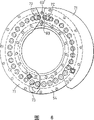
Fig. 2 is the schematic end of Fig. 1 fastening apparatus;
Fig. 3 is the assembled sectional view of the fastening apparatus of Fig. 1 and 2, and first and second article shown in it, fastening apparatus are located at the position intermediate of the position of Fig. 1 and 4;
Fig. 4 is the assembled sectional view of the fastening apparatus of Fig. 1 to 3, and shown first and second work, fastening apparatus are positioned at operating position;
Fig. 5 is the cutaway view of second embodiment of fastening apparatus of the present invention, and shown fastening apparatus is in operating position, and first and second article are with fastening; And
Fig. 6 is the schematic end of Fig. 5 fastening apparatus.
(5) specific embodiment
Consult Fig. 1, fastening apparatus 1 comprises that one is hollow annular outer cover 2 basically, and it comprises in all sidewalls 4 and axially in the outer peripheral sidewall 3, radially end wall 5.For annular solid one axial outer radial end wall is set by the closure plate 6 that is connected in two sidewalls once some soket head cap screw (not shown).Axial inner ends wall 5 is provided with some interior annular shoulders 7.Annular seal with O ring spare 8 is positioned on the shoulder 7.One annular recess 9 is arranged between the shoulder.One annular piston 10 is positioned at the shell 2 of fastening apparatus.This piston has overall for the cross section of T shape and be provided with annular shoulder 11, one annular bars 12 and be arranged between the shoulder.Some seal with O ring spares 13 are resisted against on the shoulder 11.
16 position (see figure 2)s around annular outer cover 2 are provided with many additional structural features in fastening apparatus.In each position, radially end wall 5 is provided with a hole 14 (Fig. 1) in axially, and these holes have identical diameter, cooperate with recess 9.A localization part of piston that is the form of plunger 15 is positioned at the hole, and plunger scribbles grease and forms in the hole and is slidingly matched.Bar 12 adjacency of plunger and piston.At the off position of fastening apparatus, plunger 15 passes hole 14, and surpass shell 2 axially in the inner surface of end wall 5 radially.One cavity 16 is arranged on and leads in each the annular outer cover of piston of 16 positions, and folded six disc springs 16 ' are positioned at this cavity.Size when these disc springs 16 ' are in relaxed state can make them leave piston to stretch out from cavity.When closure plate 6 was screwed onto shell, these disc springs were compressed and act on the axial inner ends wall 5 of on the piston piston 10 being pushed to shell 2, made plunger 15 pass hole 14 and exceeded shell 2.Being provided with of hydraulic means 17 is as follows.Two positions in the sidewall 3 of shell 2 are provided with opening 17 '.These openings 17 ' be arranged on piston 10 and body 2 axially in radially first annular chamber 18 between the end wall 5 cooperate.In piston, be provided with some passage (not shown) with first annular chamber is connected in be arranged on piston 10 and axially in second annular chamber 19 between the end wall 5 radially.Opening 17 ' is used to guide hydraulic fluid to enter these cavitys and an opening is used for removing hydraulic fluid from these chambeies.
Fastening apparatus also comprises a pair of fastening arm 20.Each arm comprises an arc, and is connected in closure plate 6 pivotly by a pin 21 (Fig. 2), make they can from Fig. 1 and 3 and Fig. 2 dotted line shown in open position move to the closed position shown in the solid line of Fig. 2 and 4.Spring catch 40 is positioned at hole 41 makes fastening arm 20 be fixed on open position.For fastening arm is placed on the closed position, from hole 41, take out this pin, make these arms turn to the closed position, again pin is put into hole 42 they are fixed.The shell 2 of fastening apparatus axially in radially end wall 5 be provided with the annular lip 22 that can hold one or more pins 23.
Consult Fig. 1,3 and 4, the operation of fastening apparatus will be described below.Fastening apparatus is used to make a roll 30 relative cylindrical rollers bearings 31 fixing.Fastening apparatus is placed between first end of first end of roll and roll bearing.Locate by the phase breaker roll by abutting against the shoulder (not shown) on the roll for second end of roll bearing.Second end of roll is fixed in second roll bearing by a fastening apparatus as the described herein.Shown roll bearing comprises a cylindrical bearing follower 32, and it is provided with the end 33 that a diameter dwindles.This end is provided with edge 34.Fastening apparatus axially in radially the edge 22 of end wall 5 be positioned on the end 33, and sell 23 back that are positioned at the edge 34 of supporting follower, in case fastening apparatus breaks away from the supporting follower because of carelessness.The edge is placed to that fastening apparatus remains in the supporting follower reliably but can it moves axially relatively, fastening apparatus is connected in the supporting follower movably like this.What know is that fastening apparatus can remain in the individual appropriate location of supporting follower, does not need therefrom to take off this equipment and makes roll bearing break away from roll.
First end of roll 30 comprises a neck 35 and the head 36 that a diameter dwindles.For roll is anchored on roll bearing, its first end inserts the hole of passing roll bearing, and neck 35 fastened equipment are surrounded, and head 36 stretches out the closure plate 6 of fastening apparatus, as shown in Figure 1.The diameter of roll is similar to supporting follower 32, and roll is slidingly matched in the supporting follower.The axial length of fastening apparatus (ring edge 22 forecloses) is about 61 millimeters usually at off position as shown in Figure 1, greater than the axial length of the neck 35 of roll.In this position, fastening arm 20 extends across neck 35, as shown in Figure 1, and is positioned at head 36 discontiguous positions with roll, as shown in Figure 2.
In order to make fastening apparatus work, hydraulic means 17 is directed to first annular chamber 18 with the grease in the grease compressor through a hole 17 ', and enters second annular chamber 19 from these those passages in piston 10.Import fluid in these chambeies make the elastic force of the some folded disc springs 16 ' of piston 10 opposings leave shell axially in end wall 5 radially.This makes plunger 15 withdrawal again, only stretch out slightly fastening apparatus shell 2 axially in end wall 5 radially.This radially stays annular gap 37 between end wall 5 and the end 33 of supporting follower in axially, as shown in Figure 1.Therefore, the axial length of fastening apparatus (ring edge 22 still forecloses) foreshortens to and is about 59.5 millimeters usually, and is shorter than the axial length of the neck 35 of roll.Fastening apparatus moves axially along supporting follower 32 then, makes plunger 15 in abutting connection with the supporting follower.Fastening arm 20 can be contained in the axial length of neck 35 now, and swings to the semi-circular portions (Fig. 4) that meshes and center on the neck 35 of roll respectively with counterclockwise and clockwise direction.Be placed on spring catch 40 in the hole 42 and operate C clamp 43 (Fig. 2), fastening like this arm just is fixed on this position.From chamber 18,19, discharge hydraulic fluid then.Some folded disc springs 16 ' are just shifted plunger 15 with the end 33 of supporting follower onto by piston 10 and are engaged, and by closure plate 6 fastening arm 20 are shifted onto with the axial inner surface of the head 36 of roll and to be engaged.At this operating position, the axial length of fastening apparatus (ring edge 22 still forecloses) generally is 60 millimeters, and plunger 15 is the inside radial end wall 5 of projecting shaft slightly, and piston does not contact with end wall 5 as shown in the figure.Usually, this fastening apparatus produces about 2 tons power.When second end of roll bearing is resisted against the shoulder of roll, forces first end of roll to leave first end of roll bearing, thereby make roll and roll bearing fixed relative to one another.
For the relative roll bearing of roll is unclamped, making fastening apparatus as described below is work.Again with hydraulic fluid introduction chamber 18,19, make the active force of the some folded disc springs 16 ' of piston 10 opposings leave axially in end wall 5 radially.This makes plunger 15 withdraw in the hole 14 of wall 5 again, thereby forms an annular gap between the end 33 of wall 5 and supporting follower.Fastening apparatus 33 moves axially towards the end, is released then and the contacting of the head 36 of disengaging and roll.Hydraulic fluid is discharged from the chamber then.
Roll bearing also comprises a supporting, and this supporting is heated and expands in use.When second end of roll bearing was resisted against the shoulder of roll, this end can not move, and the result that supporting is expanded axially moves first end of supporting follower towards first end of export-oriented roll.Need this moving is limited in for example 0.3 to 0.9 millimeter, otherwise, roll bearing supports follower breaker roll deviation position mutually with it, causes the follower wearing and tearing.In the present invention, the fastening apparatus at operating position applies about 2 tons power between supporting follower and roll.When the supporting follower is heated to can overcome this power the time, will push plunger 15, and plunger 15 is resisted the active force push piston 10 of some folded disc springs 16 '.This makes the axis of the piston to moving towards export-oriented closure plate 6.Piston will move continuously, be pressed towards closure plate fully until disc spring 16 ', will no longer expand at this place's supporting follower.Fastening apparatus is designed to when the operating position before any heating of supporting follower, and the distance between the axial outer end of piston 10 and the closure plate 6 is about 0.5 millimeter.Therefore, the maximum swelling of the supporting follower that can be allowed is 0.5 millimeter.The adjacency of piston and closure plate provides a favourable stop for the supporting follower.The supporting follower will be provided with a producer maximum swelling tolerance, and the maximum swelling that fastened equipment received should be less than or equal to this tolerance.
When cooling down, supporting can shrink.Plunger then can shift out and leave shell under the influence of this folded disc spring, apply a power on the supporting follower it is back into the axial location that it needs.
Fig. 5 and 6 illustrates second embodiment of fastening apparatus.This fastening apparatus is designed to it can be connected in to semipermanent roll bearing at least, thereby but Min. ground uses crane that this equipment is coupled on the roll bearing.This equipment comprises that one is the hollow annular outer cover of part 50, and it comprises in all sidewalls 52 and axially in the outer peripheral sidewall 51, radially end wall 53.For annular solid one axial outer radial end wall is set by the closing cap 54 that is connected in two sidewalls once some soket head cap screws 55.Axial inner ends wall 53 is provided with some interior annular shoulders 56.One annular recess 57 is arranged between all shoulders.One annular piston 58 is positioned at the shell 50 of fastening apparatus.This piston has overall for the cross section of T shape and be provided with some annular shoulders 59.Some annular seal with O ring spares 60 are resisted against on all shoulders 59.
32 position (see figure 6)s around annular outer cover 50 are provided with many additional structural features in fastening apparatus.In each position, radially end wall 53 is provided with a hole 61 (Fig. 5) in axially, cooperates with recess 57.Piston comprises a localization part 62 that is rod type, and this part is movably received within the recess 63 that is arranged in the piston body.Bar is positioned at the hole and formation is slidingly matched in the hole.Bar comprises one first cylindrical part 64 and one and second cylindrical part 65 that links together of plate 66.One folded disc spring 67 is centered around the part 64 between piston body and the plate 66.Compressed spring with barre 62 push to shell 50 axially in end wall 53 radially, make it pass hole 61 and stretch out shell.One die forming spring 68 is around second cylindrical part 65 of bar and act in plate 66 and shell axial radially between the end wall 53, bar is pushed away this wall towards piston body.
The hydraulic means 69 of fastening apparatus comprises an opening 69 ' (Fig. 6), is fit to grease compressor is connected thereon, and this opening and is arranged on piston 58 and cooperates with the annular chamber 70 (Fig. 5) between the closing cap 54.
Fastening apparatus also comprises a pair of fastening arm 71 (Fig. 6).Each arm comprises an arc, and 72 is connected in closing cap 54 pivotly by a pin, makes it to move to as shown in the figure closed position from open position.Spring index pin (not shown) is placed in the hole in the shell makes fastening arm be fixed on open position.For fastening arm is placed on the closed position, from the hole, take out these pins, allow these arms to turn to the closed position, by other hole and a hook circle 73 of these pins being put into shell they are fixed again.The outer peripheral sidewall 51 of the shell 50 of fastening apparatus is provided with the annular lip 74 that can hold one or more pin (not shown).
The operation of fastening apparatus will be described below.Fastening apparatus is used to make a roll 75 relative cylindrical rollers bearings 76 to be fixed together.Fastening apparatus is placed between first end of first end of roll and roll bearing.Second end of roll bearing is by abutting against a shoulder (not shown) on the roll and the setting of phase breaker roll.Second end of roll is fixed in second roll bearing by a fastening apparatus as the described herein.Fastening apparatus at first is connected in roll bearing.Roll bearing comprises a cylindrical bearing follower 77, it be provided with one by bolting in roll bearing (need to its carry out the modification of a little or without revising) dividing plate 78.Dividing plate is provided with a recess 79.The flange 74 of the outer peripheral sidewall 51 of fastening apparatus is arranged in this recess 79.This allows fastening apparatus to rotate and a certain amount of axially-movable between equipment and roll bearing relative to roll bearing, but can prevent that fastening apparatus breaks away from roll bearing because of carelessness.Know that fastening apparatus can remain in the appropriate location on the roll bearing, do not need to make roll bearing break away from roll from wherein taking off this equipment.
First end of roll 75 comprises a neck 80 and the head 81 that a diameter dwindles.For roll is anchored on roll bearing, at first open position is placed and remained on to the fastening arm 71 of fastening apparatus.First end of roll inserts the hole of passing in the roll bearing then, and neck 80 fastened equipment are surrounded, and head 81 stretches out the closing cap 54 of fastening apparatus, as shown in Figure 5.The diameter of roll is similar to supporting follower 77, and roll is slidingly matched in the supporting follower.Being formulated to equipment at the axial length of the fastening apparatus of this embodiment can be between the head 81 of supporting follower 77 and roll.Place fastening arm 71 then and be fixed on the closed position, in this position, fastening arm is placed to the neck 80 around roll.
In order to make fastening apparatus work, the grease in the grease compressor is directed to annular chamber 70 through an opening 69 '.Importing grease in this chamber provides one piston 58 to be pushed away closing cap 54, push the bar 62 of piston 58 to support the axial external surface of follower 77 and make some folded disc springs 67 and the hydraulic pressure of die forming spring 68 compressions.Have enough hydraulic pressure to put on equipment to realize the design external force of equipment, this power is 50 tons in this embodiment.A screw thread retainer 82 that is arranged on around the piston turns to operating position then, and provides other guarantee as a mechanical caging for the location of piston.Take off grease compressor then.Keep hydraulic pressure in fastening apparatus, this hydraulic pressure is pushed into bar 62 with supporting follower 77 and engages, and by closing cap 54 fastening arm 71 is pushed into the axial inner surface of roll head 81 and engages.When second end of roll bearing was resisted against a shoulder of roll, first end that forces first end of roll to push away roll bearing made the relative roll bearing of roll fixed to one another.Fastening apparatus for example is designed to bear the overload force of 100 to 200 ton forces that may occur when using roll/roll bearing assembly.
For the relative roll bearing of roll is unclamped, fastening apparatus is not worked.With grease introduction chamber 70, hydraulic pressure is increased slightly again, retainer 82 turns to off position like this.The shut-off plug of taking-up in a hole 83 (Fig. 6) of fastening apparatus discharged the grease in the chamber 70, and hydraulic pressure is released like this.This makes piston rod 62 withdrawals and breaks away from supporting follower 77.This motion has obtained the help of the step-down of mold formed spring 68.The release of hydraulic pressure also makes some folded disc spring 67 step-downs, thereby removes power all in the equipment.Then fastening arm 71 is placed and remained on open position, thereby can from roll bearing and fastening apparatus, take out roll.
In use, roll bearing can move apart fastening apparatus (for example about 0.5 to 1 millimeter), or first end of roll bearing and the distance between the roll may increase because of wearing and tearing.This may make fastening apparatus be applied at least a portion loss of the power of roll and roll bearing.But when being compressed under the effect of some folded disc springs 67 at hydraulic pressure, if roll bearing in this way moves with alternate manner, then spring 67 makes bar 62 push away the body of piston 68 effect and towards the supporting follower 77 of roll bearing and engage.Like this, disc spring breaker roll and roll bearing apply a power, promptly provide a Payload by these disc springs.The ratio that is put on the original power of roll bearing and roll by hydraulic means is kept by these disc springs.
Claims (4)
1. fastening apparatus is used for axially shifting a cylindrical support onto on a roll holding position, and in this holding position, an end of roll passes and stretch out an end of described supporting member, and described equipment comprises:
One annular outer cover, structure and size are set for can be in the position axis of the close described end of supporting member to being installed on the roll end;
Fastener engages with adjacency section in the roll end to stop described shell to leave the axially movable mode of described supporting member;
One can be in described shell axially movable annular piston;
A plurality of spring parts that act on the described piston, these spring parts are positioned at the position that separates around described shell circumference, and described spring part is used for applying resistance described shell be pushed on described adjacency section and enter described holding position by described piston action to force described supporting member; And
Act on the fluid pressure device on the described piston, removing described resistance, and described fastener can be installed on the roll end or from the roll end thus and remove described fastener.
2. fastening apparatus as claimed in claim 1 is characterized in that, the axial length of described fastening apparatus changes between the operating position between described supporting member and the described adjacency section at an axial unconfined off position and an axial constraint.
3. fastening apparatus as claimed in claim 2, it is characterized in that, fastening apparatus is bigger than the distance between supporting member and described adjacency section at the axial length of the off position of removing from roll, and the described axial length of equipment is reduced it can be placed between described supporting member and the described adjacency section at operating position.
4. fastening apparatus as claimed in claim 3 is characterized in that, described piston is forced to against described spring part by hydraulic means, with the axial length of reduction equipment, thereby makes it can be positioned at operating position.
Applications Claiming Priority (2)
| Application Number | Priority Date | Filing Date | Title |
|---|---|---|---|
| GBGB0022813.0A GB0022813D0 (en) | 2000-09-18 | 2000-09-18 | Fastening apparatus and method |
| GB0022813.0 | 2000-09-18 |
Related Parent Applications (1)
| Application Number | Title | Priority Date | Filing Date |
|---|---|---|---|
| CNB018181198A Division CN100423860C (en) | 2000-09-18 | 2001-05-22 | Fastening apparatus and method |
Publications (2)
| Publication Number | Publication Date |
|---|---|
| CN1695840A CN1695840A (en) | 2005-11-16 |
| CN1305592C true CN1305592C (en) | 2007-03-21 |
Family
ID=9899628
Family Applications (2)
| Application Number | Title | Priority Date | Filing Date |
|---|---|---|---|
| CNB2005100528691A Expired - Fee Related CN1305592C (en) | 2000-09-18 | 2001-05-22 | Fastening apparatus and method |
| CNB018181198A Expired - Fee Related CN100423860C (en) | 2000-09-18 | 2001-05-22 | Fastening apparatus and method |
Family Applications After (1)
| Application Number | Title | Priority Date | Filing Date |
|---|---|---|---|
| CNB018181198A Expired - Fee Related CN100423860C (en) | 2000-09-18 | 2001-05-22 | Fastening apparatus and method |
Country Status (16)
| Country | Link |
|---|---|
| US (2) | US6892562B2 (en) |
| EP (2) | EP1318878B1 (en) |
| JP (1) | JP3825747B2 (en) |
| KR (1) | KR100522075B1 (en) |
| CN (2) | CN1305592C (en) |
| AT (2) | ATE335555T1 (en) |
| AU (2) | AU5858701A (en) |
| BR (1) | BR0113951A (en) |
| CA (1) | CA2422505C (en) |
| DE (2) | DE60121972T2 (en) |
| ES (2) | ES2265430T3 (en) |
| GB (2) | GB0022813D0 (en) |
| MX (1) | MXPA03002380A (en) |
| RU (1) | RU2252340C2 (en) |
| WO (1) | WO2002024360A1 (en) |
| ZA (1) | ZA200302138B (en) |
Families Citing this family (29)
| Publication number | Priority date | Publication date | Assignee | Title |
|---|---|---|---|---|
| DE102005022440A1 (en) * | 2005-05-14 | 2006-11-16 | Sms Demag Ag | Mounting for roller in rolling mill with axially sprung thrust locking profiles to lock the roller drive when the roller is removed |
| SE529022C2 (en) | 2005-06-17 | 2007-04-10 | Sandvik Intellectual Property | Roll and ring for roll comprising a spring means |
| US7500374B2 (en) * | 2007-04-03 | 2009-03-10 | Morgan Construction Company | Apparatus for urging an oil film bearing onto and off of a roll neck in a rolling mill |
| US8021055B2 (en) | 2007-09-05 | 2011-09-20 | Siemens Industry, Inc. | Mechanical lock for rolling mill oil film bearing |
| US20090118809A1 (en) * | 2007-11-02 | 2009-05-07 | Torsten Scheuermann | Endoprosthesis with porous reservoir and non-polymer diffusion layer |
| CN101648262B (en) * | 2009-08-29 | 2012-01-11 | 湖南九一连续铸轧实业有限责任公司 | Puller resetting device on shifting bearing block of twin-roll cast-rolling mill |
| CN102433627B (en) * | 2011-10-11 | 2014-11-05 | 绍兴华裕纺机有限公司 | Locking device of air valve switch |
| US9334890B2 (en) | 2012-01-24 | 2016-05-10 | Kennametal India Limited | Hardmetal roll clamping system onto the shaft and the method thereof |
| US9744576B2 (en) | 2013-06-19 | 2017-08-29 | Barnes Group Inc. | Lock ring |
| RU2536601C1 (en) * | 2013-11-27 | 2014-12-27 | Николай Митрофанович Панин | Drill bit flushing assembly |
| RU2539069C1 (en) * | 2014-02-05 | 2015-01-10 | Николай Митрофанович Панин | Flushing assembly of drilling bit (versions) |
| RU2536884C1 (en) * | 2014-02-05 | 2014-12-27 | Николай Митрофанович Панин | Flushing assembly of drilling bit (versions) |
| RU2536885C1 (en) * | 2014-02-05 | 2014-12-27 | Николай Митрофанович Панин | Flushing assembly of drilling bit (versions) |
| RU2539076C1 (en) * | 2014-02-05 | 2015-01-10 | Николай Митрофанович Панин | Flushing assembly of drilling bit (versions) |
| RU2539073C1 (en) * | 2014-02-05 | 2015-01-10 | Николай Митрофанович Панин | Flushing assembly of drilling bit (versions) |
| RU2539079C1 (en) * | 2014-02-05 | 2015-01-10 | Николай Митрофанович Панин | Flushing assembly of drilling bit (versions) |
| RU2537420C1 (en) * | 2014-02-05 | 2015-01-10 | Николай Митрофанович Панин | Flushing unit of drill bit (versions) |
| RU2539075C1 (en) * | 2014-02-05 | 2015-01-10 | Николай Митрофанович Панин | Flushing assembly of drilling bit (versions) |
| RU2539080C1 (en) * | 2014-02-05 | 2015-01-10 | Николай Митрофанович Панин | Flushing assembly of drilling bit (versions) |
| RU2537738C1 (en) * | 2014-02-05 | 2015-01-10 | Николай Митрофанович Панин | Flushing assembly of drilling bit (versions) |
| US9573178B2 (en) * | 2015-01-30 | 2017-02-21 | Novelis Inc. | Split ring and method of using improved split ring to assemble a roll |
| US10794421B2 (en) | 2016-03-01 | 2020-10-06 | The Timken Company | Apparatus and method for preloading bearing assemblies |
| RU2617745C1 (en) * | 2016-04-07 | 2017-04-26 | Николай Митрофанович Панин | Flushing assembly of drilling bit (versions) |
| RU2611779C1 (en) * | 2016-04-07 | 2017-03-01 | Николай Митрофанович Панин | Flushing assembly of drilling bit (versions) |
| RU2618707C1 (en) * | 2016-04-07 | 2017-05-11 | Николай Митрофанович Панин | Flushing assembly of drilling bit (versions) |
| RU2618734C1 (en) * | 2016-04-07 | 2017-05-11 | Николай Митрофанович Панин | Flushing assembly of drilling bit (versions) |
| RU2618726C1 (en) * | 2016-04-07 | 2017-05-11 | Николай Митрофанович Панин | Flushing assembly of drilling bit (versions) |
| RU2618717C1 (en) * | 2016-04-07 | 2017-05-11 | Николай Митрофанович Панин | Flushing assembly of drilling bit (versions) |
| KR102070027B1 (en) * | 2018-07-03 | 2020-01-29 | 주식회사 삼우에코 | Swing type clamping device |
Citations (10)
| Publication number | Priority date | Publication date | Assignee | Title |
|---|---|---|---|---|
| CN87100391A (en) * | 1986-03-08 | 1987-10-28 | Skf有限公司 | Be particularly suitable for the rolling bearing that the fast mill work roll is used |
| CN87105651A (en) * | 1986-08-23 | 1988-03-16 | Sms舒路曼-斯玛公司 | Axially adjust and produce the device of shaped steel with rolls of rolling stand |
| US4776078A (en) * | 1987-07-06 | 1988-10-11 | Howard Robert S | Sleeve mounting and removal tool |
| US5029461A (en) * | 1988-02-18 | 1991-07-09 | N H C, Inc. | Hydraulic fastener |
| JPH06292912A (en) * | 1993-04-09 | 1994-10-21 | Nippon Steel Corp | Thrust ring for roll of rolling mill, mounting structure including chock and attaching/detaching method |
| CN2191048Y (en) * | 1994-02-22 | 1995-03-08 | 本溪钢铁公司 | Axial fixator for roll |
| CN2193777Y (en) * | 1993-12-31 | 1995-04-05 | 本溪钢铁公司 | Axial roll-adjusting device |
| US5600987A (en) * | 1993-10-06 | 1997-02-11 | Achenbach Buschhutten Gmbh | Device for positioning and locking a chock on a roll pin during installation of a set of rolls in or removal from a roll stand |
| CN2249135Y (en) * | 1996-05-09 | 1997-03-12 | 冶金工业部重庆钢铁设计研究院 | Axial adjusting device for rolling mill |
| EP1034854A2 (en) * | 1999-03-09 | 2000-09-13 | SKET Walzwerkstechnik GmbH | Device for mounting, securing and dismounting a ring roll clamped on an cantilevered roll shaft |
Family Cites Families (11)
| Publication number | Priority date | Publication date | Assignee | Title |
|---|---|---|---|---|
| US3627388A (en) * | 1970-09-08 | 1971-12-14 | Morgan Construction Co | Hydraulic locking and loosening device for bearing |
| US3822081A (en) * | 1973-03-08 | 1974-07-02 | Morgan Construction Co | Axial roll adjustment means |
| US3966282A (en) * | 1973-08-31 | 1976-06-29 | Republic Steel Corporation | Bearing chocking assembly for mill rolls |
| US4000638A (en) * | 1975-03-31 | 1977-01-04 | United States Steel Corporation | Plate mill finishing stand roll latch ring |
| US4341426A (en) * | 1980-10-22 | 1982-07-27 | The Timken Company | Clamp-up device for roll neck bearings |
| SE462572B (en) * | 1988-05-03 | 1990-07-16 | Skf Ab | DEVICE FOR TWO PAIRS INSTALLED ROLLING STORAGE TAKING UP TO AXIAL AND RADIAL LOADING |
| DE8807036U1 (en) * | 1988-05-30 | 1989-10-05 | Martin Schaaf Hydraulik - Spanntechnik, 5140 Erkelenz, De | |
| CN2122010U (en) * | 1992-03-04 | 1992-11-18 | 冶金工业部北京钢铁设计研究总院 | Axially regulating device for roller of rolling mill |
| CN2165942Y (en) * | 1993-06-16 | 1994-05-25 | 涟源钢铁总厂 | Axial regulating mechanism for high stiffness rolling mill |
| US6042273A (en) * | 1998-10-28 | 2000-03-28 | Colonial Tool Group Inc. | Adjustable preload spindle |
| US6132101A (en) * | 1999-07-28 | 2000-10-17 | Voest Alpine Industries, Inc. | Roll bearing assembly having integral components |
-
2000
- 2000-09-18 GB GBGB0022813.0A patent/GB0022813D0/en not_active Ceased
-
2001
- 2001-05-22 BR BR0113951-7A patent/BR0113951A/en not_active IP Right Cessation
- 2001-05-22 JP JP2002528419A patent/JP3825747B2/en not_active Expired - Lifetime
- 2001-05-22 AU AU5858701A patent/AU5858701A/en active Pending
- 2001-05-22 KR KR10-2003-7003879A patent/KR100522075B1/en active IP Right Grant
- 2001-05-22 DE DE60121972T patent/DE60121972T2/en not_active Expired - Lifetime
- 2001-05-22 AU AU2001258587A patent/AU2001258587B2/en not_active Ceased
- 2001-05-22 EP EP01931896A patent/EP1318878B1/en not_active Expired - Lifetime
- 2001-05-22 CN CNB2005100528691A patent/CN1305592C/en not_active Expired - Fee Related
- 2001-05-22 RU RU2003111022/11A patent/RU2252340C2/en not_active IP Right Cessation
- 2001-05-22 CA CA002422505A patent/CA2422505C/en not_active Expired - Lifetime
- 2001-05-22 DE DE60122218T patent/DE60122218T2/en not_active Expired - Lifetime
- 2001-05-22 WO PCT/GB2001/002258 patent/WO2002024360A1/en active IP Right Grant
- 2001-05-22 EP EP05008448A patent/EP1557226B1/en not_active Expired - Lifetime
- 2001-05-22 MX MXPA03002380A patent/MXPA03002380A/en active IP Right Grant
- 2001-05-22 AT AT05008448T patent/ATE335555T1/en active
- 2001-05-22 CN CNB018181198A patent/CN100423860C/en not_active Expired - Fee Related
- 2001-05-22 AT AT01931896T patent/ATE334755T1/en not_active IP Right Cessation
- 2001-05-22 ES ES01931896T patent/ES2265430T3/en not_active Expired - Lifetime
- 2001-05-22 ES ES05008448T patent/ES2270398T3/en not_active Expired - Lifetime
- 2001-08-21 GB GB0120259A patent/GB2366835A/en not_active Withdrawn
-
2003
- 2003-03-07 US US10/393,770 patent/US6892562B2/en not_active Expired - Lifetime
- 2003-03-17 ZA ZA200302138A patent/ZA200302138B/en unknown
-
2004
- 2004-08-06 US US10/912,951 patent/US7017381B2/en not_active Expired - Lifetime
Patent Citations (10)
| Publication number | Priority date | Publication date | Assignee | Title |
|---|---|---|---|---|
| CN87100391A (en) * | 1986-03-08 | 1987-10-28 | Skf有限公司 | Be particularly suitable for the rolling bearing that the fast mill work roll is used |
| CN87105651A (en) * | 1986-08-23 | 1988-03-16 | Sms舒路曼-斯玛公司 | Axially adjust and produce the device of shaped steel with rolls of rolling stand |
| US4776078A (en) * | 1987-07-06 | 1988-10-11 | Howard Robert S | Sleeve mounting and removal tool |
| US5029461A (en) * | 1988-02-18 | 1991-07-09 | N H C, Inc. | Hydraulic fastener |
| JPH06292912A (en) * | 1993-04-09 | 1994-10-21 | Nippon Steel Corp | Thrust ring for roll of rolling mill, mounting structure including chock and attaching/detaching method |
| US5600987A (en) * | 1993-10-06 | 1997-02-11 | Achenbach Buschhutten Gmbh | Device for positioning and locking a chock on a roll pin during installation of a set of rolls in or removal from a roll stand |
| CN2193777Y (en) * | 1993-12-31 | 1995-04-05 | 本溪钢铁公司 | Axial roll-adjusting device |
| CN2191048Y (en) * | 1994-02-22 | 1995-03-08 | 本溪钢铁公司 | Axial fixator for roll |
| CN2249135Y (en) * | 1996-05-09 | 1997-03-12 | 冶金工业部重庆钢铁设计研究院 | Axial adjusting device for rolling mill |
| EP1034854A2 (en) * | 1999-03-09 | 2000-09-13 | SKET Walzwerkstechnik GmbH | Device for mounting, securing and dismounting a ring roll clamped on an cantilevered roll shaft |
Also Published As
Similar Documents
| Publication | Publication Date | Title |
|---|---|---|
| CN1305592C (en) | Fastening apparatus and method | |
| AU2001258587A1 (en) | Fastening apparatus and method | |
| AU2001258587A2 (en) | Fastening apparatus and method | |
| US4989443A (en) | Crimping apparatus | |
| US7159426B1 (en) | Quick change assembly for hydroforming punches | |
| US7386939B2 (en) | Hydraulic fast locking and loosening device for bearing assemblies of rolling-mill cylinders, and corresponding method of use | |
| US4509910A (en) | Column clamping assembly | |
| CN103016450A (en) | Actuator cylinder slider snap ring lock | |
| EP3563970B1 (en) | Rotary clamp | |
| EP2233245B1 (en) | Clamping device | |
| US20030226725A1 (en) | Apparatus and method for retarding translation between two bodies | |
| US3626450A (en) | Portable swaging tool | |
| CN213136567U (en) | Oil seal mounting tool of transport vehicle | |
| CN100343147C (en) | Bobbin holder | |
| CN103032441B (en) | Locking device | |
| JP4327058B2 (en) | Swing clamp device | |
| JP3047243B2 (en) | Cylinder with boost mechanism | |
| CA2593395C (en) | Hydroforming apparatus | |
| CN116638300A (en) | Automatic pressure release stretcher of overtravel | |
| SU1698085A1 (en) | Working rotor for automatic rotary lines | |
| US5090229A (en) | Apparatus for supporting a workpiece | |
| CN204458769U (en) | Locking device | |
| JPH03264149A (en) | Mechanism for attaching/detaching tie bar | |
| GB2095597A (en) | Expanding solder rings in pipe fittings |
Legal Events
| Date | Code | Title | Description |
|---|---|---|---|
| C06 | Publication | ||
| PB01 | Publication | ||
| C10 | Entry into substantive examination | ||
| SE01 | Entry into force of request for substantive examination | ||
| C14 | Grant of patent or utility model | ||
| GR01 | Patent grant | ||
| C17 | Cessation of patent right | ||
| CF01 | Termination of patent right due to non-payment of annual fee |
Granted publication date: 20070321 Termination date: 20130522 |