CN1304180C - Die cutter blanket-anvil locking arrangement - Google Patents
Die cutter blanket-anvil locking arrangement Download PDFInfo
- Publication number
- CN1304180C CN1304180C CNB028197275A CN02819727A CN1304180C CN 1304180 C CN1304180 C CN 1304180C CN B028197275 A CNB028197275 A CN B028197275A CN 02819727 A CN02819727 A CN 02819727A CN 1304180 C CN1304180 C CN 1304180C
- Authority
- CN
- China
- Prior art keywords
- sheath
- projection
- anvil mould
- anvil
- mould
- Prior art date
- Legal status (The legal status is an assumption and is not a legal conclusion. Google has not performed a legal analysis and makes no representation as to the accuracy of the status listed.)
- Expired - Fee Related
Links
- 230000004044 response Effects 0.000 claims abstract description 17
- 230000007246 mechanism Effects 0.000 claims abstract description 8
- 229910052751 metal Inorganic materials 0.000 claims abstract description 7
- 239000002184 metal Substances 0.000 claims abstract description 7
- 230000000295 complement effect Effects 0.000 claims description 9
- 239000004033 plastic Substances 0.000 claims description 6
- 229920003023 plastic Polymers 0.000 claims description 6
- 230000015572 biosynthetic process Effects 0.000 claims description 3
- 230000002093 peripheral effect Effects 0.000 claims description 3
- 230000008859 change Effects 0.000 claims description 2
- 238000007665 sagging Methods 0.000 claims description 2
- 210000002700 urine Anatomy 0.000 claims 3
- 230000014759 maintenance of location Effects 0.000 claims 1
- 238000004804 winding Methods 0.000 claims 1
- 239000000463 material Substances 0.000 description 10
- 229910000831 Steel Inorganic materials 0.000 description 4
- 239000010959 steel Substances 0.000 description 4
- 238000000034 method Methods 0.000 description 3
- 238000000465 moulding Methods 0.000 description 3
- 230000008569 process Effects 0.000 description 3
- 230000002457 bidirectional effect Effects 0.000 description 2
- 230000006835 compression Effects 0.000 description 2
- 238000007906 compression Methods 0.000 description 2
- 239000002991 molded plastic Substances 0.000 description 2
- 210000003739 neck Anatomy 0.000 description 2
- 230000000284 resting effect Effects 0.000 description 2
- 238000012546 transfer Methods 0.000 description 2
- 241000397426 Centroberyx lineatus Species 0.000 description 1
- JOYRKODLDBILNP-UHFFFAOYSA-N Ethyl urethane Chemical compound CCOC(N)=O JOYRKODLDBILNP-UHFFFAOYSA-N 0.000 description 1
- 230000009471 action Effects 0.000 description 1
- 239000004411 aluminium Substances 0.000 description 1
- 229910052782 aluminium Inorganic materials 0.000 description 1
- XAGFODPZIPBFFR-UHFFFAOYSA-N aluminium Chemical compound [Al] XAGFODPZIPBFFR-UHFFFAOYSA-N 0.000 description 1
- 230000005540 biological transmission Effects 0.000 description 1
- 238000005516 engineering process Methods 0.000 description 1
- 238000003780 insertion Methods 0.000 description 1
- 230000037431 insertion Effects 0.000 description 1
- 208000037805 labour Diseases 0.000 description 1
- 230000004048 modification Effects 0.000 description 1
- 238000012986 modification Methods 0.000 description 1
- 238000012856 packing Methods 0.000 description 1
- 229920002635 polyurethane Polymers 0.000 description 1
- 239000004814 polyurethane Substances 0.000 description 1
- 239000011148 porous material Substances 0.000 description 1
- 239000002689 soil Substances 0.000 description 1
- 238000010136 thermoset moulding Methods 0.000 description 1
- 229920001187 thermosetting polymer Polymers 0.000 description 1
Images


Classifications
-
- B—PERFORMING OPERATIONS; TRANSPORTING
- B41—PRINTING; LINING MACHINES; TYPEWRITERS; STAMPS
- B41F—PRINTING MACHINES OR PRESSES
- B41F27/00—Devices for attaching printing elements or formes to supports
- B41F27/12—Devices for attaching printing elements or formes to supports for attaching flexible printing formes
- B41F27/1293—Devices for filling up the cylinder gap; Devices for removing the filler
-
- B—PERFORMING OPERATIONS; TRANSPORTING
- B26—HAND CUTTING TOOLS; CUTTING; SEVERING
- B26D—CUTTING; DETAILS COMMON TO MACHINES FOR PERFORATING, PUNCHING, CUTTING-OUT, STAMPING-OUT OR SEVERING
- B26D7/00—Details of apparatus for cutting, cutting-out, stamping-out, punching, perforating, or severing by means other than cutting
- B26D7/20—Cutting beds
- B26D2007/202—Rollers or cylinders being pivoted during operation
-
- Y—GENERAL TAGGING OF NEW TECHNOLOGICAL DEVELOPMENTS; GENERAL TAGGING OF CROSS-SECTIONAL TECHNOLOGIES SPANNING OVER SEVERAL SECTIONS OF THE IPC; TECHNICAL SUBJECTS COVERED BY FORMER USPC CROSS-REFERENCE ART COLLECTIONS [XRACs] AND DIGESTS
- Y10—TECHNICAL SUBJECTS COVERED BY FORMER USPC
- Y10T—TECHNICAL SUBJECTS COVERED BY FORMER US CLASSIFICATION
- Y10T83/00—Cutting
- Y10T83/465—Cutting motion of tool has component in direction of moving work
- Y10T83/4766—Orbital motion of cutting blade
- Y10T83/4795—Rotary tool
- Y10T83/483—With cooperating rotary cutter or backup
- Y10T83/4838—With anvil backup
- Y10T83/4841—With resilient anvil surface
-
- Y—GENERAL TAGGING OF NEW TECHNOLOGICAL DEVELOPMENTS; GENERAL TAGGING OF CROSS-SECTIONAL TECHNOLOGIES SPANNING OVER SEVERAL SECTIONS OF THE IPC; TECHNICAL SUBJECTS COVERED BY FORMER USPC CROSS-REFERENCE ART COLLECTIONS [XRACs] AND DIGESTS
- Y10—TECHNICAL SUBJECTS COVERED BY FORMER USPC
- Y10T—TECHNICAL SUBJECTS COVERED BY FORMER US CLASSIFICATION
- Y10T83/00—Cutting
- Y10T83/929—Tool or tool with support
- Y10T83/9309—Anvil
- Y10T83/9312—Rotatable type
-
- Y—GENERAL TAGGING OF NEW TECHNOLOGICAL DEVELOPMENTS; GENERAL TAGGING OF CROSS-SECTIONAL TECHNOLOGIES SPANNING OVER SEVERAL SECTIONS OF THE IPC; TECHNICAL SUBJECTS COVERED BY FORMER USPC CROSS-REFERENCE ART COLLECTIONS [XRACs] AND DIGESTS
- Y10—TECHNICAL SUBJECTS COVERED BY FORMER USPC
- Y10T—TECHNICAL SUBJECTS COVERED BY FORMER US CLASSIFICATION
- Y10T83/00—Cutting
- Y10T83/929—Tool or tool with support
- Y10T83/9457—Joint or connection
- Y10T83/9464—For rotary tool
- Y10T83/9466—Flexible sleevelike tool
Abstract
A molded anvil blanket (14) is formed with a projection (24, 26) depending at each end (20, 22), the ends for abutting when wrapped about an anvil (12), the anvil having a projections (24, 26) mate to form a common recess (40) enclosed by a metal angle member (46, 48) secured to each projection. The angle member (46, 48) and projections (24, 26) have a transverse slot (58, 60) for mounting the blanket (20, 22) end and projections on a pneumatic mechanism attached to the anvil. The mechanism includes an air cylinder (66) secured to the anvil (12) in a radial anvil bore (62). The cylinder (66) has a shaft (72) which extends in response to pressurized air. A spring (116) attached to the air cylinder (66) and to a T-bar (104) which releasably engages the blanket common recess (40) normally biases the projections locked into the channel in a fail safe mode.
Description
Technical field
The present invention relates to be used in the sheet material die cutting device, die-cut die jacket is locked in locking device on the anvil mould, wherein this sheath is wrapped on the anvil mould.
Background technology
Die-cut die jacket is the thermoset molding urethane material that is wrapped on the steel circular cylindrical anvil mould.The anvil mould has an axially extended vertical hole usually and in its surface of extending along anvil mould longitudinal axis a groove is arranged.Sheath wraps on the anvil mould and has locking projection in certain embodiments.Sheath is the sheet material with opposed end edge, and locking projection is located on the above-mentioned edge.These ends be shape complementarity and locking projection engage in insertion groove the time.Locking projection interlocking in being inserted into the anvil die cavity time, thus these edge locked are being locked on the anvil mould on the sheath and sheath, prevent that thus sheath from rotating around the anvil mould.
US3765329 discloses a scheme of the sheath with such projection.Plastic sheath has the metallic plate liner.Locking projection is at bipartite clamping head of textural formation, and its center dant holds protuberance, and recess lets droop with a vertical circular groove from sheath one end edge genesis, and protuberance and circular groove are complementary and snap in the circular groove.Protuberance can be made of metal.Recess has a metab.Protuberance and recess are sagging so that insert the anvil die cavity from the sheath edge.
Other complementary type latch-up structure is disclosed in US4073207, US4848204, US3885486, US4867024, US5078535, US5720212, US5758560, US5916346 and US6135002.All above-mentioned patents have all adopted complementary locking overhung structure, and it embeds in the anvil die cavity and cooperatively interacts, and has adopted the anvil die cavity so that the sheath end is locked together and be locked on the anvil mould in the stationary fit mode in the anvil die cavity.These need force projection in the anvil die cavity of packing into to obtain locking action.Usually, projection is knocked in the groove so that the surface texture interlocking of engagement protrusion or make projection and the groove interlocking.In addition, can receive protrusion pin in the anvil die cavity with pin.
The locking device that another sheath end locks together has used interlaced interlocking to refer to, interlocking finger-type shape roughly is swallow-tail form.Interlocking refers to be in the plane identical with sheath sheet material and covers on the anvil mould.The anvil mould has a groove.Interlocking refers to overlay on the groove.Sheath interlocking plunger end has one and is embedded in the anvil die cavity to prevent the projection of dangling of the relative anvil mould rotation of sheath.
Summary of the invention
The problem of said structure is that the locking projection that inserts in the anvil die cavity is in the stationary fit joint usually.This need knock in projection in the anvil die cavity.This is a trouble.Equally, need the reverse operating process for taking out sheath, this in addition more difficult because need prize the anvil die cavity to the sheath end.This is to use a large amount of labours' operation and implementation cost high.The inventor recognizes to be needed a kind ofly to implement fast, economical more and sheath locking devices more can simple and direct loading and unloading.
According to the present invention, alleviated the problems referred to above by a kind of die-cut anvil mould-jacket assembly, this assembly comprises the die-cut die jacket of plastics that is positioned at a plane and has opposed end, wherein there is the projection that hangs down and from the plane each end.One anvil roller has outer surface and vertical first hole that limits the anvil mould around the axis of its rotation, axially extended groove is together arranged on the anvil mould outer surface, sheath its opposite end and projection against each other descend to encase the anvil mould, projection is positioned at groove under lock-out state.One pneumatic means is fixed on the anvil mould and cooperates with sheath and reaches the sheath lock-out state so that selectively projection is fixed in the groove and selectively projection is shifted out groove outer and transfer the sheath released state to.
In a scheme, the anvil mould comprises radially second hole that communicates with groove and anvil mould first hole, and pneumatic means comprises that one is fixed in anvil mould first hole and cooperates so that selectively sheath is forwarded to the cylinder of released state from lock-out state with second hole.
In another program, pneumatic means comprises a spring of bias voltage sheath under lock-out state usually.
In another scheme, cylinder comprises a bar, and it also comprises a york piece that is fixed on the cylinder rod in response to the compressed air ground extension of input, and york piece comprises one releasably with protrusion engagement so that in response to the bar parts of mobile projection movably.
In another scheme, cylinder comprises a bar, pneumatic means comprises a spring, this spring has predetermined bias and is connected with bar with the anvil mould, this bar in response to the spring bias voltage be withdrawn into lock-out state and be used in response to the input cylinder compressed air and be stretched over released state with overcoming the spring bias voltage.
In another program, a fastener is fixed on the anvil mould and is arranged to cylinder is fixed on the there.
This fastener preferably includes first parts that are fixed in the anvil die cavity and second parts that dangle from first parts and be positioned at radial hole, and second parts are fixed on this cylinder.
In another program, the projection of each sheath end has a recess, under lock-out state, the recess of projection cooperatively interacts under the situation of adjacent sheath end butt, and pneumatic means comprises that one releasably engages so that projection moves on to the parts of the locking and unlocking state with unique recess.
In another program, projection has the slit respectively one, and these slits cooperatively interact so that releasably hold these parts.
In another scheme, sheath comprises that is positioned at a plastics plate plane and that first, second opposed end is arranged, and this plate is used for wrapping in the anvil mould under the situation of the mutual butt in end.One first projection is folded down from first end, one second projection hangs down from the second end, first, second projection has a recess away from this plane earth respectively, described recess is used to form a unique complementary recess that extends along the sheath end, and it is radially opening wide on that recess side on plate plane under the situation of end butt.One first parts are connected on the first end of sheath, thereby form one recess wall on a recess side.
In a scheme; die-cut die jacket anvil mould has the longitudinal axis of an anvil mould around its rotation; sheath has opposed end and each end projection of dangling; these projections have a public cavity, and anvil mould outer peripheral face has together transverse to this axis groove that extend and be used for holding projection under the sheath lock-out state.The anvil mould comprises first an elongated bar, and it has first anvil mould hole that extends along y direction.A plurality of radially second holes are positioned at first bar, and each second hole communicates with this groove and first anvil mould hole.Pneumatic means is fixed on each place, second hole radially in first anvil mould hole of anvil mould, and pneumatic means has one second bar, it in response to the Pneumatic pressure ground that is applied to that radially stretching in second hole separately.Sheath engaging mechanism is fixed on second bar so that releasably engage the opposed end of sheath, thereby projection is carried away this trough transfers the sheath released state to from the lock-out state in groove with stretching in response to second bar.Be provided with a sheath fastener in this mechanism, it is used under lock-out state projection being remained in the groove, so that sheath releasably is locked on the anvil mould.
Description of drawings
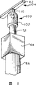
Fig. 1 represents sheath and anvil mode locking device and assembly according to an embodiment of the invention with the partial side sectional view;
The zone 2 of Fig. 2 to show in detail assembly shown in Figure 1;
Fig. 3 shows in detail the situation of sheath anvil mode locking device under the closed-lock state shown in Fig. 1,2 with partial cross section's end-view;
Fig. 4 represents to be in the locking device of opening released state with the view that is similar to Fig. 3;
Fig. 5 represents to be used to open cylinder and T bar and york piece with closed Fig. 3,4 locking device with stereogram;
Fig. 6 represents the engaging of metal bight of one of T bar and york piece and Fig. 1, sheath two edges of 2 equally with the view that is similar to Fig. 5;
Fig. 7 represents to be connected to difform cylinder on the Building T with stereogram, and the Building T is fixed on york piece and cylinder is and the part of this sheath metal liner and reinforce the metal angle part and be fixed on this lining in the sheath end region;
Fig. 8 represents the lining that uses with the embodiment of the invention with stereogram;
Fig. 9 is with the T bar and the york piece of the detailed presentation graphs 5,6 of partial side sectional view;
Figure 10 represents the end edge of the butt of sheath of the present invention with the partial side sectional view;
Figure 11 shows another embodiment of the present invention with the view that is similar to Fig. 2, and it is different with spring and cylinder among Fig. 2 embodiment with spring that its medi-spring drives cylinder.
The specific embodiment
In Fig. 1, the assembly 10 in the present embodiment comprises a steel circular cylindrical anvil mould 12, and the anvil mould has a longitudinal axis 18 and the die-cut die jacket 14 of one group of butt is arranged vertically, and they wrap on the anvil mould 12.Assembly 10 is used in the equipment, and in this equipment, mould is punched in the sheet material (not shown) of rotation anvil mould 12 and sheath 14 top processes.In die-cut process, when this sheet material above sheath through out-of-date, slab material such as hardboard etc. are punched.The anvil mould 12 of Fig. 3 has a groove 16, and this groove extends the length that reaches the anvil mould along the anvil mold shaft line 18 of Fig. 1.The cross section of the groove 16 of Fig. 3 is square or rectangle, and this depends on given instrument.Anvil mould 12 is hollow and an axially extended hole 13 is arranged.The bearing (not shown) is installed in one with anvil mould 12 and makes the anvil mould and install additional on the transmission device that sheath rotates.
Fig. 4,10 typical sheath 14 have the end 20 ' and 22 ' identical with other sheath 14.Sheath 14 is the molding sheet material of polyurethane plastics (thermosetting plastics), and two end edge 20,22 of sheet material end at end 20 ' and 22 ' separately.Two molding projections 24,26 hang down from end 20 ' and 22 ' separately.These projections are complementary and form the unique combination projection 28 (Figure 10) complementary with groove 16 (Fig. 3), so that sheath 14 is rotated relative to anvil mould 12 along with 12 rotations of anvil mould.Described projection closely is contained in the groove 16, rather than stationary fit with it.These projections can with groove 16 stationary fit slightly, fit snugly in this groove to guarantee the combination projection.
One leg 50 of parts 46 is welded on the lining leg 32 and is enclosed in the moulded plastic of projection 24.Another leg 52 crosses this shared this hole or opening recess 40 so that seal this hole or opening recess 40 at other open sides away from plane 42.The end edge of leg 52 is against on the projection 26, perhaps can be spaced apart with projection 26 slightly, thereby in this hole or other this hole of open sides base closed or opening recess 40 of opening recess 40.
Similarly, a leg 54 of parts 48 is welded on the lining 30 ' leg 34, and its another leg 56 meets at right angles with leg 54, and the leg 52 of it and parts 46 is arranged side by side.Parts 46,48 are steel preferably.The Plastic Package leg 34,54 of projection 26.The leg 56 of parts 48 has slit 58 one, and the leg 52 of parts 46 has slit 60 one, and place under the situation of edge 20 and 22 butts side by side in slit 58 and 60, as shown in figure 10, and places side by side with the part of hole or opening recess 40.
In Fig. 1, (only illustrate) in this embodiment, anvil mould 12 has a row axially extended and at this rectangular opening 62 of 12 same radial orientations preferably, these rectangular openings communicate with anvil mould 12 outer peripheral faces 64 and hole 13.One operating means such as cylinder 66 are corresponding with each hole 62.In Fig. 1,2, each cylinder 66 has one to be fixed on parts 68 on the anvil mould 12 by a fastener 70.In addition, each cylinder 66 has a bar 72 and is unidirectional cylinder.This means that bar 72 only stretches owing to the compressed air of being imported on a direction 74.When the pressure removal, this bar is released and is moving freely on the direction 74 ' of direction 74.
In Fig. 2,7, fastener 70 comprises an essential part 76 and a lateral part 78.In Fig. 7, for clarity sake and only show lining 30 and dress thereon angle- shaped piece 46,48 and demonstrate relation between the parts.Essential part 76 can be separated with lateral part 78 and be fixed by unshowned screw.Perhaps, essential part and lateral part can be made by unitary steel material or aluminium.In Fig. 7, fastener 70 is fixed on the cylinder portion 68 by screw 80.Essential part 76 is parts that a cross section becomes rectangle.Lateral part 78 becomes the flat part of rectangle for cross section.Part 78 has arm 82 and 84.Arm 82 has through hole 86, and arm 84 has through hole 88.Among Fig. 2, screw 90,92 is fixed on arm 82,84 by hole 86,88 in anvil die cavity 16 diapires 96 of anvil mould recess 94 of anvil mould 12.Essential part 76 has a through hole 98.
In Fig. 3,4,8, a cylindrical bush 101 is installed in the hole 98.Can conceal into the ground mounting bush, so that make the inwall isoplanar in it and hole 98 by unshowned mode.Lining can be fixed in the hole 98 by interference fit.
In Fig. 5,9, yoke assembly 100 comprises a york piece 102, and it is fixed on the sheath transverse junction element 104, sheath transverse junction element 104 can be as shown in figure one or constitute (not shown) by the two parts that are screwed onto together.York piece 102 is a cylinder tube shape spare, has an axial medium pore 105 and cross through hole 106 and them aligned with each other to hold pin 109 on the opposite side of york piece 102.Hole 105 holds the bar 72 of cylinder 66.By passing the pin 109 in cylinder rod 72 holes 105, bar 72 is fixed on the york piece 102 and by being fixed in the hole 106 as the interference fit or the (not shown) that is threaded.
This lateral part 104 is fixed on the york piece 102 by neck 110.Lateral part 104 has half-cylindrical cross section 112, shown in the end-view of Fig. 5.Lateral part 104 is embedded in this hole of sheath projection 24,26 (Figure 10) or the opening recess 40 and the shape complementarity of its shape and this hole or opening recess 40 as illustrated in fig. 3, and is cylindrical as the one-tenth part.
One end of a coil compression springs 116 is fixed on the cylinder part 68 (Fig. 3), and its other end is fixed on cylinder rod 72 or the york piece 100.Spring 116 is biased in the resting position of Fig. 3 usually, wherein goes up pulling york piece downwards by spring in direction 74 '.This lateral part with yoke assembly 100 is locked on the sheath latched position of Fig. 1-3.
At work, in Fig. 4, cylinder is stretched by applying compressed air.Compressed air is transfused in the one-tenth exhaust casing of Fig. 1 simultaneously.Controller 122 is received compressed air source on the export pipeline 124.Export pipeline 124 is by on pipeline 126 parallel intake pipeline 127-130 that are connected to exhaust casing 66 etc.Therefore, all cylinder rods 72 extend the sheath released state of Fig. 4 simultaneously.One at a time sheath 14 is installed on the anvil mould, the sheath 14 of Fig. 4 is exactly representative.
On desired location as shown in Figure 4, a sheath 14 loosely wraps on the anvil mould.For ease of explanation, turned up the soil at interval in sheath end 20 ' and 22 ' and be arranged on this anvil mould top.On direction 118 and 120, make end 20 ' and 22 ' close mutually.The leg separately 52 and 56 of parts 46,48 also moves on these directions.During moving, each slit 60 and the 58 common necks 110 of admitting yoke assembly.Leg 52 and 56 is overlapping when mobile on these directions, up to sheath end edge 20 and 22 butts.Each recess 36 and 38 forms the hole or the opening recess 40 of combination when butt, referring to Fig. 3.In this position, the transverse junction element 104 of yoke assembly 100 is positioned at this hole or opening recess 40 and extends beyond on the overlapping leg 52,54 at (Fig. 1) on axis 18 directions.Transverse junction element 104 also is positioned at the top of the groove of anvil mould hole 62 arbitrary examples.
Then, residue sheath 14 in a row is installed on the yoke assembly separately that is fixed on the anvil mould 12 successively, all be in place until them, and its end edge mutual butt but have certain distance ground to be positioned at above the anvil mould as illustrated in fig. 4 as illustrated in fig. 3.At this moment, the controller 122 of application drawing 1 so that from pipeline 124 with become exhaust casing 66 remove compressed air.Basically with removal pressure from cylinder side by side, spring 116 makes yoke assembly be retracted to the lock-out state position of Fig. 3 automatically.This move forces projection 24,26 to enter in anvil mould 12 grooves 16 and the end 20 ' and 22 ' of sheath 14 in a row and is locked in the anvil die cavity 16 of Fig. 1-3.Just in case compressed air source and controller 122 lost efficacy and the compressed air forfeiture, this has guaranteed safe operation.Not the pressure feed cylinder time, spring 16 always makes sheath keep lock-out state.
For making sheath be in released state, once more compressed air is supplied with different cylinders 66, so that all cylinder rods 72 extend to the released state of Fig. 4.Where necessary, remove the sheath of choosing in these sheaths 14 and change new.
Although spring has guaranteed safe operation as shown in figure when compressed air is lost, will occur a kind of can be in response to the two-way cylinder of compressed air ground bidirectional operation.In other words, on two rightabouts, alternatively compressed air is supplied with this cylinder, so that cylinder rod is positioned at locking or released state by a controller (not shown).The compressed-air line that this has been avoided the use spring and may need to add.But do not guarantee safe operation in this case.In addition, where necessary, can provide bidirectional operation like this, promptly cylinder combines with spring so that the feature of compressed air locking sheath to be provided.
Embodiment among Figure 11 is similar to Fig. 2, except that cylinder with spring is different.In two figure, the part that same-sign is arranged is identical.In Figure 11, cylinder 123 has a bar 124, and it further radially stretches in the anvil mould hole 13 from cylinder at part 130 places.The elongated end 132 of part 130 has screw thread and holds nut 128 so that spring 126 is fixed on the bar 124.In this position, this spring extends on its resting position.When air pressure supply cylinder 123, interior and spring 126 compressions of bar portion 130 retraction cylinders.When removal pressure, spring 126 makes bar portion 130 be back to the extended position of Figure 11.
For those of ordinary skills, under the situation that does not break away from the spirit and scope of the present invention, can carry out modification miscellaneous to described embodiment.The disclosed embodiments are exemplary rather than restrictive.The scope of the invention is limited by follow-up claims.
Claims (23)
1, die-cut mould anvil mould-jacket assembly (10), it comprises:
The tabular die-cut die jackets of plastics (14) with opposed end (20 ', 22 '), each described end has a sagging projection (24,26);
An anvil mould (12), this anvil mould has outer surface (64) and limits vertical first hole (13) of anvil mould around the axis (18) of its rotation, described anvil mould has axially extended groove (16) together on described outer surface, under described opposed end and described projection situation against each other, this sheath is wrapped on the described anvil mould, described projection (24,26) is positioned at described groove (16) under lock-out state;
An operating means (66), it is fixed on described anvil mould (12) and goes up and be connected on the described sheath (14), so that selectively described projection (24,26) is fixed in the described groove (16) under the lock-out state of described sheath and released state at described sheath under selectively make described projection shift out described groove.
2, assembly as claimed in claim 1 is characterized in that, described operating means is a pneumatic means.
3, assembly as claimed in claim 2, it is characterized in that, described anvil mould (12) comprises radially second hole (62) that communicates with vertical first hole (13) of described groove (16) and described anvil mould, described pneumatic means comprise in first hole that is fixed on described anvil mould (12) and cooperate so that selectively described sheath is transferred to the cylinder (66) of described released state from described lock-out state with described second hole.
4, assembly as claimed in claim 1 is characterized in that, described operating means comprises a spring (116), and it is the described sheath of locking under lock-out state usually.
5, assembly as claimed in claim 2 is characterized in that, described pneumatic means comprises a spring (116), and it is these projections of locking under lock-out state usually.
6, assembly as claimed in claim 3, it is characterized in that, described cylinder comprises a bar (72), described bar stretches in response to the compressed air of input, described cylinder also comprises a york piece (102) that is fixed on the described bar, described york piece comprises that one releasably engages so that forward the sheath locking piece (104) of described released state in response to the end that makes described projection and described sheath movably of described bar (72) with described projection (24,26).
7, assembly as claimed in claim 3, it is characterized in that, described cylinder comprises a bar (72), this pneumatic means comprises a spring (116), described spring has predetermined bias and is connected with described bar (72) with described anvil mould (12), described bar be withdrawn into described lock-out state in response to the bias voltage of described spring and be used in response to the compressed air that inputs to described cylinder and overcome described spring bias voltage be stretched over described released state.
8, assembly as claimed in claim 3 is characterized in that, it comprise one be fixed on the described anvil mould (12) and be arranged to described cylinder (66) fastener (70) fixed thereon.
9, assembly as claimed in claim 8, it is characterized in that, described fastener (70) comprise one in the described groove that is fixed on described anvil mould first lateral part (78) and second essential part (76) that hangs down and come and be positioned at described radially second hole (62) from described first lateral part, described second essential part is fixed on the described cylinder.
10, assembly as claimed in claim 1, it is characterized in that, these projections on each end have a recess (36,38), these recesses of described projection cooperatively interact under the situation of the mutual butt in the end of described sheath and form unique opening recess (40), and described operating means comprises that one releasably engages so that make described projection and described sheath end move on to the sheath locking piece (104) of described lock-out state and described released state with described unique opening recess (40).
11, assembly as claimed in claim 10 is characterized in that, these projections have one slit (58,60) respectively, and these slits cooperate so that releasably admit described sheath locking piece (104).
12, the die-cut die jacket (14) that uses with anvil mould (12), described anvil mould has the longitudinal axis (18) of a described anvil mould around its rotation, and the groove that extends transverse to described axis is together arranged on the surface (64) of described anvil mould, and described sheath comprises:
Urine gastral cavity plate (14), it is positioned at a plane and has opposed first end and the second end (20 ', 22 '), and described urine gastral cavity plate is used under the situation of end butt the winding residence and states the anvil mould;
From described first end hang down first projection (24) of coming and second projection (26) that hangs down and from described the second end, described first projection and described second projection have a recess (36 away from described plane respectively, 38), these recesses are used to form unique complementary recess (40), complementary recess extend along described sheath end and on the recess side on described urine gastral cavity plate plane, opening wide under the situation of described end butt;
At first parts (46) that are fixed on the described first end on the described sheath, it is used for forming a recess wall on described recess side, described first parts have an edge, the slit (60) in described first parts this with recess side that described edge communicates in described recess wall, form one and run through opening.
13, sheath as claimed in claim 12 is characterized in that, it comprises that also one is being fixed on the described the second end on the described sheath and second parts (48) overlapping with described first parts.
14, sheath as claimed in claim 13 is characterized in that, described second parts (48) have a slit (58) side by side, slit with described first parts.
15, sheath as claimed in claim 12 is characterized in that, it is L shaped that described first parts (46) become, and it has second leg (52) that is connected usually transverse to first leg (50) on described first projection on this plane and the described recess wall of formation.
16, sheath as claimed in claim 13, it is characterized in that, described first parts (46) become L shaped with described second parts (48), they have first leg (50 that is connected usually transverse on not same in first projection separately on described plane and second projection respectively, 54) and be in second leg (52,56) of described overlapping relation.
17, sheath as claimed in claim 16, it is characterized in that, described sheath comprises a metal liner (30) that is fixed on this plate (14), this lining has the 3rd leg (32) and the 4th leg (34) is arranged in this second projection in described first projection, described first parts (46) are fixed on described the 3rd leg (32), and described second parts (48) are fixed on described the 4th leg (34).
18, sheath as claimed in claim 12 is characterized in that, at least one parts in described first parts (46) and described second parts (48) are arranged to partially enclosed at least described complementary recess.
19, die-cut die jacket anvil mould; it has the longitudinal axis (18) of a described anvil mould around its rotation; described sheath have opposed end (20 '; 22 ') and each described end a projection of dangling (24 is arranged; 26); these projections have a shared cavity (40), have one transverse to described axis (18) groove (16) that extend and be used for holding described projection under the sheath lock-out state on the outer peripheral face (64) of described anvil mould, and described anvil mould comprises:
Elongated first bar (12), it has first anvil mould hole (13) that Y extends;
A plurality of radially second holes (62) that are positioned at first bar, each described second hole communicates with described groove (16) and described first anvil mould hole (13);
Operating means (66), it be connected in first anvil mould hole (13) of described anvil mould each radially second hole (62) go up and have in response to adding air pressure and second bar (72) that in each described radially second hole, stretches;
Be connected the sheath engaging mechanism (100 on described second bar (72), 104,110), it is used for releasably engaging the opposed end of described sheath (14), thus in response to the stretching, extension of described second bar (72) make described projection move on to the state of unlocking from lock-out state;
Holding device (104,46,48,52,56,116), it remains in the described groove described projection so that releasably described sheath (14) is locked on the described anvil mould under the sheath lock-out state.
20, anvil mould as claimed in claim 19 is characterized in that, this holding device comprises that one is connected with described anvil mould so that usually described projection is locked in elastic component (116) in the described groove (16).
21, anvil mould as claimed in claim 19 is characterized in that, described operating means comprises a cylinder (66), and it is made a response to the compressed air of selectively input.
22, anvil mould as claimed in claim 21, it is characterized in that, described cylinder (66) has described second bar (72) that the input compressed air because of the application of force stretches, described sheath engaging mechanism comprises a yoke assembly (100), described yoke assembly comprise one in described radially second hole (62), receive on described second bar (72) and the york piece (102) outside first party protrudes upward described radially second hole, one be connected on the described york piece (102) and extend upward so that be contained in the described groove (16) and engage the sheath fastener (104) of described sheath in second party perpendicular to described first direction, described second bar (72) is stretched over the sheath released state in response to input compressed air from lock-out state, the described sheath fastener (104 of described sheath engaging mechanism, 110,100,72,66) be used for making this yoke assembly that described projection is drawn in described groove and enter the sheath lock-out state and described projection is released described groove and change the sheath released state outward in response to the stretching, extension of described second bar (72) ground.
23, anvil mould as claimed in claim 22, it is characterized in that in radially second hole (62) of each described anvil mould, also having an essential part (76), one to be connected the lateral part (78) on this essential part and the described groove that be fixed on described anvil mould and be used for described cylinder (66) is fixed on retention mechanism on the described essential part.
Applications Claiming Priority (2)
| Application Number | Priority Date | Filing Date | Title |
|---|---|---|---|
| US09/971,983 | 2001-10-05 | ||
| US09/971,983 US6612214B2 (en) | 2001-10-05 | 2001-10-05 | Die cutter blanket-anvil locking arrangement |
Publications (2)
| Publication Number | Publication Date |
|---|---|
| CN1564728A CN1564728A (en) | 2005-01-12 |
| CN1304180C true CN1304180C (en) | 2007-03-14 |
Family
ID=25519016
Family Applications (1)
| Application Number | Title | Priority Date | Filing Date |
|---|---|---|---|
| CNB028197275A Expired - Fee Related CN1304180C (en) | 2001-10-05 | 2002-10-01 | Die cutter blanket-anvil locking arrangement |
Country Status (8)
| Country | Link |
|---|---|
| US (1) | US6612214B2 (en) |
| EP (1) | EP1432557B1 (en) |
| CN (1) | CN1304180C (en) |
| AT (1) | ATE337143T1 (en) |
| DE (1) | DE60214208T2 (en) |
| ES (1) | ES2271377T3 (en) |
| HK (1) | HK1063300A1 (en) |
| WO (1) | WO2003035339A1 (en) |
Families Citing this family (7)
| Publication number | Priority date | Publication date | Assignee | Title |
|---|---|---|---|---|
| ATE464164T1 (en) * | 2004-10-12 | 2010-04-15 | Fosber Spa | MACHINE FOR LENGTH CUTTING WEB-SHAPED MATERIAL, IN PARTICULAR CORRUGATED CARBON |
| US20060191390A1 (en) * | 2005-02-25 | 2006-08-31 | Neal Kenneth R | Die cutter blanket/anvil locking system |
| GB2451232B (en) * | 2007-07-21 | 2009-07-08 | Tech Ni Fold Ltd | Creasing rings |
| GB2458153A (en) * | 2008-03-06 | 2009-09-09 | Ostomart Ltd | Cut supporting device, system and method |
| US9773863B2 (en) * | 2014-05-14 | 2017-09-26 | Infineon Technologies Austria Ag | VDMOS having a non-depletable extension zone formed between an active area and side surface of semiconductor body |
| EP3352976A1 (en) | 2015-09-23 | 2018-08-01 | Day International, Inc. | Cutting mats and methods of making same |
| CA3022326A1 (en) * | 2016-04-26 | 2017-11-02 | Sun Automation, Inc. | Feed/pull roll system with detachable elastomeric feed-covers, and process for cover replacement |
Citations (7)
| Publication number | Priority date | Publication date | Assignee | Title |
|---|---|---|---|---|
| US3602970A (en) * | 1969-04-14 | 1971-09-07 | Ward Turner Machinery Co | Latch bar assembly for replaceable cover |
| US3739675A (en) * | 1972-02-07 | 1973-06-19 | Dayco Corp | Rotary anvil construction |
| US4073207A (en) * | 1976-12-22 | 1978-02-14 | Robud Co. | Lock for rotary die cutting blanket |
| US4191076A (en) * | 1978-10-23 | 1980-03-04 | Dayco Corporation | Rotary anvil construction |
| US4848204A (en) * | 1988-06-22 | 1989-07-18 | Corfine Inc. | Die cutter blanket |
| US5078535A (en) * | 1989-03-02 | 1992-01-07 | Robud Co. | Locking means |
| US5916346A (en) * | 1997-10-14 | 1999-06-29 | Robud | Die cutter blanket |
Family Cites Families (4)
| Publication number | Priority date | Publication date | Assignee | Title |
|---|---|---|---|---|
| US3765329A (en) * | 1971-09-28 | 1973-10-16 | A Kirkpatrick | Cylinder cover fastening devices |
| US5076128A (en) * | 1990-04-26 | 1991-12-31 | Connor Barry J O | Die cutter blanket |
| US5720212A (en) * | 1995-03-22 | 1998-02-24 | Robud | Locking arrangement for die cutter blanket |
| US6135002A (en) * | 1998-04-27 | 2000-10-24 | Neal; Kenneth Ray | Die cutter blanket and bearing and method of arranging the blanket and bearing on an anvil |
-
2001
- 2001-10-05 US US09/971,983 patent/US6612214B2/en not_active Expired - Lifetime
-
2002
- 2002-10-01 CN CNB028197275A patent/CN1304180C/en not_active Expired - Fee Related
- 2002-10-01 WO PCT/US2002/031145 patent/WO2003035339A1/en active IP Right Grant
- 2002-10-01 DE DE2002614208 patent/DE60214208T2/en not_active Expired - Lifetime
- 2002-10-01 EP EP20020802110 patent/EP1432557B1/en not_active Expired - Lifetime
- 2002-10-01 ES ES02802110T patent/ES2271377T3/en not_active Expired - Lifetime
- 2002-10-01 AT AT02802110T patent/ATE337143T1/en not_active IP Right Cessation
-
2004
- 2004-08-11 HK HK04106021A patent/HK1063300A1/en not_active IP Right Cessation
Patent Citations (7)
| Publication number | Priority date | Publication date | Assignee | Title |
|---|---|---|---|---|
| US3602970A (en) * | 1969-04-14 | 1971-09-07 | Ward Turner Machinery Co | Latch bar assembly for replaceable cover |
| US3739675A (en) * | 1972-02-07 | 1973-06-19 | Dayco Corp | Rotary anvil construction |
| US4073207A (en) * | 1976-12-22 | 1978-02-14 | Robud Co. | Lock for rotary die cutting blanket |
| US4191076A (en) * | 1978-10-23 | 1980-03-04 | Dayco Corporation | Rotary anvil construction |
| US4848204A (en) * | 1988-06-22 | 1989-07-18 | Corfine Inc. | Die cutter blanket |
| US5078535A (en) * | 1989-03-02 | 1992-01-07 | Robud Co. | Locking means |
| US5916346A (en) * | 1997-10-14 | 1999-06-29 | Robud | Die cutter blanket |
Also Published As
| Publication number | Publication date |
|---|---|
| EP1432557A1 (en) | 2004-06-30 |
| DE60214208D1 (en) | 2006-10-05 |
| EP1432557B1 (en) | 2006-08-23 |
| ES2271377T3 (en) | 2007-04-16 |
| ATE337143T1 (en) | 2006-09-15 |
| US20030066402A1 (en) | 2003-04-10 |
| CN1564728A (en) | 2005-01-12 |
| WO2003035339A1 (en) | 2003-05-01 |
| HK1063300A1 (en) | 2004-12-24 |
| DE60214208T2 (en) | 2007-10-11 |
| US6612214B2 (en) | 2003-09-02 |
Similar Documents
| Publication | Publication Date | Title |
|---|---|---|
| CN1304180C (en) | Die cutter blanket-anvil locking arrangement | |
| CN1040194C (en) | Anchoring device for securing an end piece of a cord wound uponto a storage reel | |
| CN101247945A (en) | Drum for a creasing device | |
| CN1730191A (en) | Bending machine die provided with a vise for clamping an elongated workpiece to be bent | |
| KR100802085B1 (en) | Variability circumference forming mechanism of tire | |
| CN1071861C (en) | Expandable shaft | |
| US6352602B1 (en) | Bead wire winding device and winding method | |
| CN1066414C (en) | Improved expanding shaft | |
| US6872353B2 (en) | Method of molding using compact molding apparatus | |
| CN1322172A (en) | Strip fitting tools and methods | |
| EP0845311A1 (en) | Silencer shell forming apparatus | |
| CN1347356A (en) | Device for fracture-separating workpiece | |
| CN112974556A (en) | Die core replacing device of drawing machine and using method thereof | |
| CN2374723Y (en) | Improved structure of mechanical union joint | |
| CN2329607Y (en) | Size changeable frame for packing | |
| CN1106256C (en) | Method for producing plastic container | |
| CN1301811C (en) | Method and system for support and/or transport of a wire | |
| CN101767422A (en) | Mold clamping mechanism and injection-molding method | |
| CN1191400C (en) | Roller for guiding knitgoods on knitting machine and device manufactured by the roller | |
| CN1097168A (en) | Act on the anti-theft column lock on the auto steerer | |
| JPH0314609B2 (en) | ||
| CN100455846C (en) | Tensioner for a timing chain | |
| JPH0737797Y2 (en) | Nut feeder for automatic fasteners | |
| JP3151059B2 (en) | Insert loader device | |
| CN219866680U (en) | Gap plugging mechanism and embedded pipeline |
Legal Events
| Date | Code | Title | Description |
|---|---|---|---|
| C06 | Publication | ||
| PB01 | Publication | ||
| C10 | Entry into substantive examination | ||
| SE01 | Entry into force of request for substantive examination | ||
| C14 | Grant of patent or utility model | ||
| GR01 | Patent grant | ||
| CF01 | Termination of patent right due to non-payment of annual fee |
Granted publication date: 20070314 Termination date: 20191001 |
|
| CF01 | Termination of patent right due to non-payment of annual fee |