CN1300621C - Multi-beam optical scanning apparatus, and image forming apparatus using the same - Google Patents
Multi-beam optical scanning apparatus, and image forming apparatus using the same Download PDFInfo
- Publication number
- CN1300621C CN1300621C CNB2004100319066A CN200410031906A CN1300621C CN 1300621 C CN1300621 C CN 1300621C CN B2004100319066 A CNB2004100319066 A CN B2004100319066A CN 200410031906 A CN200410031906 A CN 200410031906A CN 1300621 C CN1300621 C CN 1300621C
- Authority
- CN
- China
- Prior art keywords
- scanning direction
- light beam
- face
- scanned
- main scanning
- Prior art date
- Legal status (The legal status is an assumption and is not a legal conclusion. Google has not performed a legal analysis and makes no representation as to the accuracy of the status listed.)
- Expired - Fee Related
Links
Images


Classifications
-
- B—PERFORMING OPERATIONS; TRANSPORTING
- B41—PRINTING; LINING MACHINES; TYPEWRITERS; STAMPS
- B41J—TYPEWRITERS; SELECTIVE PRINTING MECHANISMS, i.e. MECHANISMS PRINTING OTHERWISE THAN FROM A FORME; CORRECTION OF TYPOGRAPHICAL ERRORS
- B41J2/00—Typewriters or selective printing mechanisms characterised by the printing or marking process for which they are designed
- B41J2/435—Typewriters or selective printing mechanisms characterised by the printing or marking process for which they are designed characterised by selective application of radiation to a printing material or impression-transfer material
- B41J2/47—Typewriters or selective printing mechanisms characterised by the printing or marking process for which they are designed characterised by selective application of radiation to a printing material or impression-transfer material using the combination of scanning and modulation of light
- B41J2/471—Typewriters or selective printing mechanisms characterised by the printing or marking process for which they are designed characterised by selective application of radiation to a printing material or impression-transfer material using the combination of scanning and modulation of light using dot sequential main scanning by means of a light deflector, e.g. a rotating polygonal mirror
- B41J2/473—Typewriters or selective printing mechanisms characterised by the printing or marking process for which they are designed characterised by selective application of radiation to a printing material or impression-transfer material using the combination of scanning and modulation of light using dot sequential main scanning by means of a light deflector, e.g. a rotating polygonal mirror using multiple light beams, wavelengths or colours
Abstract
An object is to obtain a multi-beam optical scanning apparatus in which a displacement of an image location of each of light beams emitted from a plurality of light emitting portions is reduced, and which is suitably usable in a high-speed and high-image-quality application, and an image forming apparatus using the multi-beam optical scanning apparatus. A multi-beam optical scanning apparatus includes a light source unit 1 having plural light emitting portions disposed with being spaced from each other in a main-scanning direction, a first optical system 2 for changing conditions of plural divergent light beams emitted from the light source unit, a stop 3 for restricting widths of the plural light beams transmitted through the first optical system, a deflecting unit 5 for reflecting the plural light beams restricted by the stop, a second optical system 6 for forming images of the plural light beams reflected by the deflecting unit on a surface 7 to be scanned, and a detecting unit for detecting a writing start position synchronous signal for controlling a timing of a scanning start position on the surface to be scanned. The individual elements are designed so as to satisfy a predetermined condition.
Description
Technical field
The image processing system that the present invention relates to multi-beam optical scanning apparatus and use it, be specially adapted to use that the light supply apparatus with a plurality of luminescence units is realized at a high speed, high record density, for example have image processing systems such as the laser printer of electrofax program and digital copier, multi-function printer.
Background technology
Figure 23 is the major part sectional view (main sweep sectional view) of main scanning direction of the main sweep optical devices of multi-beam optical scanning apparatus in the past.In same figure, have a plurality of luminescence units (luminous point), for example many light beams that penetrate from multi-beam semiconductor laser 91 are transformed to almost parallel light beam or converging beam by collimation lens 92, limit the size of this beam cross section by unthreaded hole diaphragm 93, incide cylindrical lens 94.The light beam that incides cylindrical lens 94 in the main sweep cross section with original state outgoing, near convergence and deflection face 95a, be imaged as the focal line shape of on main scanning direction, extending in the subscan cross section as the polygonal mirror 95 of light deflector.The deflection face 95a reflection by the polygonal mirror 95 that rotates with a fixed angular speed on the arrow A direction in the drawings then retrodeviates each light beam to scanning, become point-like by f θ lens 96 optically focused optically focused on the face of forming by sensitization magnetic drum etc. that is scanned 97, scan with certain speed on the arrow B direction in the drawings.On sensitization magnetic drum surface 97, carry out image recording thus as recording medium.
In such multi-beam optical scanning apparatus,, generally be before writing out picture signal, to be provided with to write out the position synchronous signal supervisory instrument for the position of writing out of control chart picture correctly.
At this in Figure 23, the 78th, the mirror of turning back (BD catoptron) reflexes to BD sensor 81 1 sides described later to the light beam (BD light beam) that the position synchronous input uses that writes out of the timing that is used to detect the scanning starting position on the sensitization magnetic drum 97.The 79th, slot-shaped parts (BD slit) are configured on the position with sensitization magnetic drum surface 97 optical equivalences.The 80th, the BD lens are to be used for BD catoptron 78 and BD sensor 81 are set to the lens that optical conjugate concerns, revise the skew of BD catoptron 78.The 81st, as the optical sensor (BD sensor) that writes out the position synchronous signal detection component.At this, each key element such as BD catoptron 78, BD slit 79, BD lens 80, BD sensor 81 constitutes a key element of writing out position synchronous signal supervisory instrument (BD optical system).In same figure, detect output signal, the timing of writing out the position when adjusting on sensitization magnetic drum surface 97 document image from BD sensor 81.
In such multi-beam optical scanning apparatus, such as shown in figure 24, if a plurality of luminescence unit A, B (has represented 2 luminescence unit A for convenience in same figure, B, but more than 3 too) in the vertical alignment arrangements on sub scanning direction, then because also open significantly than recording density at the interval that is scanned the sub scanning direction sweep trace separately on the face, so usually as shown in figure 25 a plurality of luminescence unit A, the B tilted configuration is on main scanning direction, by adjusting its angle of inclination δ, make in sub scanning direction scan line spacings and the recording density separately that is scanned on the face and as one man correctly adjust.
In the multi-beam optical scanning apparatus of above-mentioned various formations in the past, because a plurality of luminescence unit A, B tilted configuration on main scanning direction, so as shown in figure 26, each light beam that penetrates from a plurality of luminescence unit A, B arrives the position of leaving main scanning direction at the deflection face 95 of polygonal mirror 95, and because also different separately, so on the position of departing from main scanning direction mutually, be imaged as point (light A and light B) on the face 97 being scanned from the angle of each light beam of deflection face 95 reflection of polygonal mirror 95.
Thereby, in the multi-beam optical scanning apparatus that constitutes like this, only with the stipulated time δ T timed sending picture signal that staggers, make the light beam that penetrates from a certain benchmark luminescence unit consistent with image space on the position that is scanned imaging on the face from the light beam of another luminescence unit ejaculation.
The deflection face of δ T during the time that only stagger is set to the angle of the 95a ' of figure, and the light that be reflected this moment is owing to be reflected to B ' direction, promptly identical with light A direction (angle), thereby the image space unanimity of mutual point.
But, at this moment because of certain reason, for example when because of the optical unit that keeps optical system and be scanned the site error of face, assembly error in the time of on this optical unit, can assembling optical element etc., taken place under the situation that the main sweep focus departs from (focus of the optical axis direction of f θ lens 96 departs from), be offset to 97 ' position from the tram if for example be scanned face 97 in this hypothesis, then from same figure as can be known, the image space of each light only produces δ Y on main scanning direction
1Depart from.
In the past, owing to produce the skew δ Y of the image space of main scanning direction from the light beam of multiple light courcess (light supply apparatus) with a plurality of such luminescence units
1, thereby have the problem that causes the reduction of lettering precision, image quality deterioration.
As the method that solves such problem, in the patent documentation 1 that the applicant mentions in front, disclose focal length by setting the collimation lens best, the deflection face from the iris to the polygonal mirror distance, f θ lens main scanning direction focal length, multiple light courcess main scanning direction luminous point at interval etc., alleviate light beam from above-mentioned multiple light courcess effectively at the skew δ of the image space of main scanning direction Y
1Technology.
By taking the mode of above-mentioned patent documentation 1, can be image space skew δ Y from the main scanning direction of the light beam of multiple light courcess
1Be relieved to the no problem level that goes up of using.
[patent documentation 1] USP6489982 communique
On the other hand, if many light beams that incide on the sensitization magnetic drum surface are turned back to luminescence units such as semiconductor laser once more by normal reflection on the sensitization magnetic drum surface, then laser is sent out the instability of shaking.In addition, when above-mentioned normal reflection light returned optical system, because the surface reflection of optical system, reflected light might be got back to the sensitization magnetic drum surface once more and produce ghost phenomena.
Therefore, the angle that is set at the chief ray of many light beams that incide the sensitization magnetic drum surface and the sub scanning direction that normal became of this sensitization magnetic drum surface as shown in figure 27 like that becomes the angle [alpha] of regulation.The normal reflection light of obtaining thus on the sensitization magnetic drum surface does not turn back to semiconductor laser and the such formation of optical system.Figure 27 is to use the major part sectional view (subscan sectional view) of sub scanning direction of the multi-beam optical scanning apparatus of multiple light courcess in the past.
In multi-beam optical scanning apparatus, under the situation of taking such formation, the length difference of a plurality of sweep traces on the sensitization magnetic drum surface as shown in figure 28.Thus, on the end of the particularly main sweep side direction on the sensitization magnetic drum surface, on the image space of a plurality of imaging points, produce the skew of main scanning direction.
The skew of the main scanning direction of this image space exists with ...: the average angle α of the chief ray that incides the above-mentioned multiple beam on the sensitization magnetic drum surface in the subscan cross section and the normal angulation of this sensitization magnetic drum surface, incide the mean value β of the normal angulation of the chief ray of the multiple beam on the sensitization magnetic drum surface of the scanning position arbitrarily in the main sweep cross section and this sensitization magnetic drum surface, the resolution of sub scanning direction (trace interval), Sao Miao number of scanning lines (number of the luminescence unit of light supply apparatus) simultaneously.
That is, the image space skew that is scanned the main scanning direction on the face 97 is the value with following value addition: because above-mentioned many luminescence units with respect to main scanning direction at sub scanning direction tilt configuration and the offset δ Y of generation
1, the offset δ Y that produces because of the angle [alpha] that the angle of the sub scanning direction that normal became that incides the chief ray of many light beams on the sensitization magnetic drum surface and this sensitization magnetic drum surface is arranged to stipulate
DSkew, thereby exist and to cause that the lettering precision lowers, the problem of image quality deterioration.
That is, adopt that disclosed method can be understood as in above-mentioned patent documentation 1: not only alleviate skew δ Y from the image space of the main scanning direction of the light beam of multiple light courcess
1, but also need consideration because of the offset δ Y that the angle initialization of the chief ray that incides many light beams on the above-mentioned sensitization magnetic drum surface and the sub scanning direction that normal became of this sensitization magnetic drum surface is produced for the angle [alpha] of stipulating
D
Summary of the invention
The objective of the invention is to: provide a kind of skew that does not need complicated adjustment just can reduce the image space of each light beam that penetrates from light supply apparatus effectively, the multi-beam optical scanning apparatus of optimum high speed and high image quality and use its image processing system with a plurality of luminescence units.
Multi-beam optical scanning apparatus with feature of the present invention is to comprise the light supply apparatus that has having the luminescence unit more than 3 or 3 at interval on main scanning direction and the sub scanning direction; The state of the divergent beams more than 3 or 3 that will penetrate from this light supply apparatus is changed into the 1st optical system of other state; The diaphragm of the width of light beam of the main scanning direction at least of the light beam more than 3 or 3 of restricted passage the 1st optical system; Reflection is by the polygonal rotating mirror of the light beam more than 3 or 3 of this diaphragm; Be scanned on the face the 2nd optical system that is imaged as imaging point at the light beam more than 3 or 3 that reflects on this polygonal rotating mirror; Detect the multi-beam optical scanning apparatus that writes out the position synchronous signal supervisory instrument of the timing signal of this scanning starting position that is scanned the imaging point on the face, it is characterized in that:
This writes out the position synchronous signal supervisory instrument has and writes out the position synchronous signal detection component, is configured in the slot-shaped parts between this light path of writing out position synchronous signal detection component and this polygonal rotating mirror,
This writes out the position synchronous signal supervisory instrument and writes out the light beam that the position synchronous signal detection component detects on this polygonal rotating mirror reflection and passed through the 2nd optical system by this, and detects the timing signal that this is scanned the scanning starting position on the face,
The S that is set to that leaves main scanning direction between farthest the luminescence unit in this luminescence unit more than 3 or 3
1
The focal length of the 1st optical system is set to f
1
The distance of the deflection face from this diaphragm to this polygonal rotating mirror is set to L
1
The focal length of the main scanning direction of the 2nd optical system is set to f
2
Incide this chief ray that is scanned the light beam more than 3 or 3 on the face and be set to α with the mean value of angle that this is scanned the sub scanning direction that normal became of face;
The chief ray that this that incides the arbitrary scan position is scanned the light beam more than 3 or 3 on the face is set to β with the mean value of angle that this is scanned the main scanning direction that normal became of face;
Focus deviation as the main scanning direction in the scanning position of this mean value β is set to δ M
(β)
The focus deviation of the main scanning direction in the scanning position of these 3 light beams more than 3 during by these slot-shaped parts is set to δ M
(BD)
Per 1 inch pixel count according to the definite main scanning direction of the resolution that is scanned the main scanning direction on the face at this is set to N
M
From this luminescence unit more than 3 or 3 leave 2 light beams that luminescence unit farthest penetrates this be scanned the imaging point on the face sub scanning direction be set to P the time, satisfy the condition of following formula:
Wherein, δ M
(β), δ M
(BD)Be defined as from being configured in the focus deviation of the light beam that penetrates with the nearest locational luminescence unit of the optical axis of the 1st optical system.
Multi-beam optical scanning apparatus with feature of the present invention is to comprise the light supply apparatus that has having the luminescence unit more than 3 or 3 at interval on main scanning direction and the sub scanning direction; The state of the divergent beams more than 3 or 3 that will penetrate from this light supply apparatus is changed into the 1st optical system of other state; The diaphragm of the width of light beam of the main scanning direction at least of the light beam more than 3 or 3 of restricted passage the 1st optical system; Reflection is by the polygonal rotating mirror of the light beam more than 3 or 3 of this diaphragm; Be scanned on the face the 2nd optical system that is imaged as imaging point at the light beam more than 3 or 3 that reflects on this polygonal rotating mirror; Detect the multi-beam optical scanning apparatus that writes out the position synchronous signal supervisory instrument of the timing signal of this scanning starting position that is scanned the imaging point on the face, it is characterized in that:
This write out that the position synchronous signal supervisory instrument has and the 2nd optical system independently the mat woven of fine bamboo strips 3 optical systems, write out the position synchronous signal detection component, be configured in the slot-shaped parts between this light path of writing out position synchronous signal detection component and the 3rd optical system,
This writes out the position synchronous signal supervisory instrument and writes out the light beam that the position synchronous signal detection component detects on this polygonal rotating mirror reflection and passed through the 3rd optical system by this, and detect the timing signal that this is scanned the scanning starting position of the imaging point on the face
The S that is set to that leaves main scanning direction between farthest the luminescence unit in this luminescence unit more than 3 or 3
1
The focal length of this mat woven of fine bamboo strips 1 optical system is set to f
1
The distance of the deflection face from this diaphragm to this polygonal rotating mirror is set to L
1
The focal length of the main scanning direction of the 2nd optical system is set to f
2
The focal length of the main scanning direction of the 3rd optical system is set to f
3
Incide this chief ray that is scanned the light beam more than 3 or 3 on the face and be set to α with the mean value of angle that this is scanned the sub scanning direction that normal became of face;
The chief ray that this that incides the arbitrary scan position is scanned the light beam more than 3 or 3 on the face is set to β with the mean value of angle that this is scanned the main scanning direction that normal became of face;
Focus deviation as the main scanning direction in the scanning position of this mean value β is set to δ M
(β)
The focus deviation of the main scanning direction in the scanning position of this light beam more than 3 or 3 during by these slot-shaped parts is set to δ M
(BD)
Per 1 inch pixel count according to the definite main scanning direction of the resolution that is scanned the main scanning direction on the face at this is set to N
M
From these 3 or 3 above luminescence units leave 2 light beams that luminescence unit farthest penetrates this be scanned the imaging point on the face sub scanning direction be set to P the time, satisfy the condition of following formula:
Wherein, δ M
(β), δ M
(BD)Be defined as from being configured in the focus deviation of the light beam that penetrates with the nearest locational luminescence unit of the optical axis of the 1st optical system.
In addition, the above-mentioned position synchronous signal supervisory instrument that writes out uses at all light beams more than 3 or 3 that reflect on the above-mentioned polygonal rotating mirror, controls the above-mentioned timing that is scanned the scanning starting position on the face.
In addition, above-mentioned slot-shaped parts can move along the direct of travel of the light beam more than 3 or 3 that incides these slot-shaped parts.
In addition, above-mentioned slot-shaped parts can rotate in the cross section with respect to the direct of travel approximate vertical of the light beam more than 3 or 3 that incides these slot-shaped parts.
In addition, on above-mentioned polygonal rotating mirror, reflect, incide the above-mentioned light beam that writes out the position synchronous signal detection component by the 2nd optical system.
Image processing system with feature of the present invention is characterised in that and comprises: above-mentioned multi-beam optical scanning apparatus; Be configured in the above-mentioned photoreceptor that is scanned on the face; By light beam by the scanning of above-mentioned multi-beam optical scanning apparatus, the electrostatic latent image that is formed on the above-mentioned photoreceptor is looked like to carry out video picture as toner imagescope; The toner that video picture is gone out looks like to be transferred to the transfer printing device that is transferred on the material; The toner that is transferred as photographic fixing in the fuser that is transferred on the material.
Image processing system with feature of the present invention is characterised in that and comprises: above-mentioned multi-beam optical scanning apparatus; Code data from external mechanical input is transformed to picture signal is input to printer controller the above-mentioned multi-beam optical scanning apparatus.
Coloured image with feature of the present invention forms device and is characterised in that and comprises: be configured in being scanned on the face of above-mentioned multi-beam optical scanning apparatus, form a plurality of picture supporting bodies of mutual different colours image.
Above-mentioned in addition coloured image forms device and comprises the view data that the colour signal from the external mechanical input is transformed to different colours, is input to the printer controller of each multi-beam optical scanning apparatus.
In addition, the multi-beam optical scanning apparatus with feature of the present invention is to comprise the light supply apparatus that has having the luminescence unit more than 3 or 3 at interval on main scanning direction and the sub scanning direction; The state of the divergent beams more than 3 or 3 that will penetrate from this light supply apparatus is changed into the 1st optical system of other state; The diaphragm of the width of light beam of the main scanning direction at least of the light beam more than 3 or 3 of restricted passage the 1st optical system; Reflection is by the polygonal rotating mirror of the light beam more than 3 or 3 of this diaphragm; Be scanned on the face the 2nd optical system that is imaged as imaging point at the light beam more than 3 or 3 that reflects on this polygonal rotating mirror; Detect the multi-beam optical scanning apparatus that writes out the position synchronous signal supervisory instrument of the timing signal of this scanning starting position that is scanned the imaging point on the face, it is characterized in that:
This writes out the position synchronous signal supervisory instrument and has the position synchronous of writing out signal detection component,
This writes out the position synchronous signal supervisory instrument and writes out the light beam that the position synchronous signal detection component detects on this polygonal rotating mirror reflection and passed through the 2nd optical system by this, and detects the timing signal that this is scanned the scanning starting position on the face,
The S that is set to that leaves main scanning direction between farthest the luminescence unit in this luminescence unit more than 3 or 3
1
The focal length of the 1st optical system is set to f
1
The distance of the deflection face from this diaphragm to this polygonal rotating mirror is set to L
1
The focal length of the main scanning direction of the 2nd optical system is set to f
2
Incide this chief ray that is scanned the light beam more than 3 or 3 on the face and be set to α with the mean value of angle that this is scanned the sub scanning direction that normal became of face;
The chief ray that this that incides the arbitrary scan position is scanned the light beam more than 3 or 3 on the face is set to β with the mean value of angle that this is scanned the main scanning direction that normal became of face;
Focus deviation as the main scanning direction in the scanning position of this mean value β is set to δ M
(β)
This light beam more than 3 or 3 is set to δ M at the focus deviation that this writes out the main scanning direction in the sensitive surface of position synchronous signal detection component
(BD)
Per 1 inch pixel count of the main scanning direction of determining according to this resolution that is scanned the main scanning direction on the face is set to N
M
From this luminescence unit more than 3 or 3 leave 2 light beams that luminescence unit farthest penetrates this be scanned the imaging point on the face sub scanning direction be set to P the time, satisfy the condition of following formula:
Wherein, δ M
(β), δ M
(BD)Be defined as from being configured in the focus deviation of the light beam that penetrates with the nearest locational luminescence unit of the optical axis of the 1st optical system.
Multi-beam optical scanning apparatus with feature of the present invention is to comprise the light supply apparatus that has having the luminescence unit more than 3 or 3 at interval on main scanning direction and the sub scanning direction; The state of the divergent beams more than 3 or 3 that will penetrate from this light supply apparatus is changed into the 1st optical system of other state; The diaphragm of the width of light beam of the main scanning direction at least of the light beam more than 3 or 3 of restricted passage the 1st optical system; Reflection is by the polygonal rotating mirror of the light beam more than 3 or 3 of this diaphragm; Be scanned on the face the 2nd optical system that is imaged as imaging point at the light beam more than 3 or 3 that reflects on this polygonal rotating mirror; Detect the multi-beam optical scanning apparatus that writes out the position synchronous signal supervisory instrument of the timing signal of this scanning starting position that is scanned the imaging point on the face, it is characterized in that:
This write out the position synchronous signal supervisory instrument have with the 2nd optical system independently the 3rd optical system, write out the position synchronous signal detection component,
This writes out the position synchronous signal supervisory instrument and writes out the light beam that the position synchronous signal detection component detects on this polygonal rotating mirror reflection and passed through the 3rd optical system by this, and detects the timing signal that this is scanned the scanning starting position on the face,
The S that is set to that leaves main scanning direction between farthest the luminescence unit in this luminescence unit more than 3 or 3
1
The focal length of the 1st optical system is set to f
1
The distance of the deflection face from this diaphragm to this polygonal rotating mirror is set to L
1
The focal length of the main scanning direction of the 2nd optical system is set to f
2
The focal length of the main scanning direction of the 3rd optical system is set to f
3
Incide this chief ray that is scanned the light beam more than 3 or 3 on the face and be set to α with the mean value of angle that this is scanned the sub scanning direction that normal became of face;
The chief ray that this that incides the arbitrary scan position is scanned the light beam more than 3 or 3 on the face is set to β with the mean value of angle that this is scanned the main scanning direction that normal became of face;
Focus deviation as the main scanning direction in the scanning position of this mean value β is set to δ M
(β)
This light beam more than 3 or 3 is set to δ M at the focus deviation that this writes out the main scanning direction in the sensitive surface of position synchronous signal detection component
(BD)
Per 1 inch pixel count according to the definite main scanning direction of the resolution that is scanned the main scanning direction on the face at this is set to N
M
From this luminescence unit more than 3 or 3 leave 2 light beams that luminescence unit farthest penetrates this be scanned the imaging point on the face sub scanning direction be set to P the time, satisfy the condition of following formula:
Wherein, δ M
(β), δ M
(BD)Be defined as from being configured in the focus deviation of the light beam that penetrates with the nearest locational luminescence unit of the optical axis of the 1st optical system.
In addition, the above-mentioned position synchronous signal supervisory instrument that writes out uses at all light beams more than 3 or 3 that reflect on the above-mentioned polygonal rotating mirror, controls the above-mentioned timing that is scanned the scanning starting position on the face.
On above-mentioned polygonal rotating mirror, reflect in addition, incide the above-mentioned light beam that writes out the position synchronous signal detection component by the 2nd optical system.
Image processing system with feature of the present invention is characterised in that and comprises: above-mentioned multi-beam optical scanning apparatus; Be configured in the above-mentioned photoreceptor that is scanned on the face; Be formed on the electrostatic latent image on the above-mentioned photoreceptor looks like to carry out video picture as toner imagescope by light beam handle with above-mentioned multi-beam optical scanning apparatus scanning; The toner that is rasterized is looked like to be transferred to the transfer printing device that is transferred on the material; The toner that is transferred as photographic fixing in the fuser that is transferred on the material.
In addition, image processing system comprises: above-mentioned multi-beam optical scanning apparatus; Code data from the external mechanical input is transformed to picture signal, is input to the printer controller in the above-mentioned multi-beam optical scanning apparatus.
Coloured image as feature of the present invention forms device, it is characterized in that comprising: be configured in the face that is scanned of above-mentioned multi-beam optical scanning apparatus separately, form a plurality of picture supporting bodies of the image of mutual different colours.
In addition, coloured image forms device and comprises: the color signal of importing from external mechanical is transformed to the view data of different colours, is input to the printer controller of each multi-beam optical scanning apparatus.
Can from following accompanying drawing, explanation, know further feature.
Description of drawings
Fig. 1 is the main sweep sectional view of embodiments of the invention 1.
Fig. 2 is the main sweep sectional view of scanning form of showing the multiple beam of embodiments of the invention 1.
Fig. 3 is a main sweep sectional view of showing the comparative example of embodiments of the invention 1.
Fig. 4 is the subscan sectional view of embodiments of the invention 1.
Fig. 5 is the figure that shows 2 sweep trace parallel sweep states on the sensitization magnetic drum surface.
Fig. 6 is the focus deviation δ M that shows in the embodiments of the invention 1
(β)Figure.
Fig. 7 is the focus deviation δ M that shows in the embodiments of the invention 1
(β)Figure.
Fig. 8 is a table of showing each numeric data in the embodiments of the invention 1.
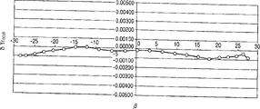
Fig. 9 is to be offset delta Y in the transverse axis curve embodiments of the invention 1 with β
FocusCurve map.
Figure 10 is to be offset delta Y in the transverse axis curve embodiments of the invention 1 with β
DCurve map.
Figure 11 is is the transverse axis curveization with β with the curve map of the offset delta Y after Fig. 9 and the offset addition shown in Figure 10.
Figure 12 is the main sweep sectional view of embodiments of the invention 2.
Figure 13 is the focus deviation δ M that shows in the embodiments of the invention 2
(β)Figure.
Figure 14 is the focus deviation δ M that shows in the embodiments of the invention 2
(β)Figure.
Figure 15 is a table of showing each numeric data in the embodiments of the invention 2.
Figure 16 is to be offset delta Y in the transverse axis curve embodiments of the invention 2 with β
FocusCurve map.
Figure 17 is to be offset delta Y in the transverse axis curve embodiments of the invention 2 with β
DCurve map.
Figure 18 is with 25.4/3N
MCurve map for the offset delta Y of transverse axis curveization after with the offset addition of the image space of Figure 16 and main scanning direction shown in Figure 17.
Figure 19 is the main sweep sectional view of embodiments of the invention 3.
Figure 20 is the enlarged drawing that writes out the position synchronous signal supervisory instrument of showing embodiments of the invention 4.
Figure 21 is the figure that shows the embodiment of image processing system of the present invention.
Figure 22 shows that coloured image of the present invention forms the major part skeleton diagram of the embodiment of device.
Figure 23 is the main sweep sectional view of multi-beam optical scanning apparatus in the past.
Figure 24 is the figure of the configuration of the multiple light courcess in the multi-beam optical scanning apparatus that is illustrated in the past.
Figure 25 is the figure of the configuration of the multiple light courcess in the multi-beam optical scanning apparatus that is illustrated in the past.
Figure 26 is the key diagram that has produced in multi-beam scanning optics in the past under the situation of focal shift.
Figure 27 is the figure of the configuration of the explanation sub scanning direction that incides light beam on the sensitization magnetic drum and magnetic drum normal.
Figure 28 is that explanation is the light beam that incides the sensitization magnetic drum and magnetic drum normal different figure of scanning multiplying power under the situation that forms the configuration of predetermined angular ground on the sub scanning direction.
Embodiment
[embodiment 1]
Fig. 1 is the major part sectional view (main sweep cross section) of main scanning direction of the multi-beam optical scanning apparatus of embodiments of the invention 1.
At this, so-called main scanning direction is meant the direction vertical with the optical axis of the rotation axis of deviator and scanning optical element (be light beam be reflected the direction of (deflection scanning)) in deviator, so-called sub scanning direction is meant the direction parallel with the rotation axis of deviator.In addition, so-called main sweep cross section is meant parallel with main scanning direction and comprises the plane of the optical axis of scanning optics.In addition, the cross section vertical with the main sweep cross section represented in so-called subscan cross section.
1 is light supply apparatus in same figure, form by a plurality of luminescence units that on main scanning direction and sub scanning direction, have at interval, in same figure by formations such as for example monolithic multi-beam semiconductor laser with 3 luminescence units (luminous point) 1a, 1b, 1c.But, in same figure, omitted luminescence unit 1b for reduced graph.Suppose that luminescence unit 1b is present in the optional position between luminescence unit 1a and the luminescence unit 1c.At this, the luminescence unit number is not limited to 3, also can be more than 4.
The 2nd, as the transform optics element (collimation lens) of the 1st optical system, change from the spot condition of 3 divergent beams of multi beam semiconductor laser 1 ejaculation.And then the so-called spot condition that changes divergent beams changes degree of divergence exactly, perhaps divergent beams is changed into parallel beam, perhaps changes into converging beam.
The 4th, cylindrical lens, the only refracting power that in the subscan cross section, has regulation.The 3rd, unthreaded hole diaphragm (diaphragm) is configured between collimation lens 2 and the light deflector 5, the width of light beam of restriction incident beam.
The 5th, as the light deflector of deviator, for example constitute by polygonal mirror (polygonal rotating mirror), drive and rotate with certain speed on the arrow A direction in the drawings by drive units such as polygonal mirror motor (not shown), thus incident beam is reflexed on the main scanning direction.
The 6th, as f θ lens combination (imaging optical system) with the 2nd optical system of f θ characteristic, by the 1st, 2 lens of 2f θ lens 6a, 6b form, in the subscan cross section, make deflection face 5a and be scanned face 7 to have roughly in the conjugate relation, the light beam based on the image information that is reflected by light deflector 5 is being imaged on as on the sensitization magnetic drum surface 7 that is scanned face.And then f θ lens combination can be made of lens single or more than 3, also can comprise diffraction optical element and constitute, and in addition, is not only lens combination, also can be reflective optics.
The 7th, as the sensitization magnetic drum surface that is scanned face.
The 8th, the mirror of turning back (BD catoptron) reflexes to BD sensor 11 described later to the light beam (BD light beam) that the position synchronous input uses that writes out of the timing that is used to detect the scanning starting position on the sensitization magnetic drum surface 7.
The 9th, slot-shaped parts (BD slit), be configured in and the position of sensitization magnetic drum surface 7 optical equivalences or its near on.
The 10th, the imaging len that synchronous detection is used (BD lens), its formation is by making BD catoptron 8 and BD sensor 11 be in conjugate relation, even the ineffective light beam that also makes all the time of the reflecting surface of BD catoptron 8 incides the BD sensor.
The 11st, synchronous detecting element (BD sensor) in the present embodiment, use to detect the synchronizing signal (BD signal) that the output signal from BD sensor 11 obtains, and control is to the timing of the scanning starting position of the image recording on the sensitization magnetic drum surface 7.
And then BD catoptron 8, BD slit 9, BD lens 10 also has each key element such as BD sensor 11 to constitute a key element writing out position synchronous signal supervisory instrument (BD optical system).Write out the position synchronous signal supervisory instrument and use via the light beam of optics deflector 5 by f θ lens series 6, control is scanned the timing of the scanning starting position on the face.
In the present embodiment, 3 divergent beams that penetrate from multi beam semiconductor laser 1 corresponding to image information incide cylindrical lens 4 by collimation lens 2 conversion spot condition.3 light beams that incide cylindrical lens 4 penetrate with previous status in the main sweep cross section, convergence and limit its cross sectional shape by unthreaded hole diaphragm 3 in the subscan cross section is imaged as near the deflection face 5a of light deflector 5 and elongates the focal line shape that extends on main scanning direction.
Because separating 3 light beams of configuration on each comfortable main scanning direction at least on the multi beam semiconductor laser 1, so 3 light beams incide deflection face 5a with different separately angles in the main sweep cross section.
Then, 3 light beams that are launched on the deflection face 5a of light deflector 5 are imaged as a little on sensitization magnetic drum surface 7 by f θ lens combination 6, by this light deflector 5 is rotated in the arrow A direction, make this sensitization magnetic drum surface 7 go up the constant speed photoscanning in arrow B direction (main scanning direction).On sensitization magnetic drum surface 7, carry out image recording thus as recording medium.
In the present embodiment, carry out as described below on each comfortable sensitization magnetic drum surface 7 of each light beam, writing out determining of starting point.
Detect the timing (BD detection) of BD sensor 11 that many light beams arrive upstream one side of the main scanning direction that is set at sensitization magnetic drum surface 7, each light beam is carried out this BD independently of one another detect, begin after the time delay of stipulating as writing out beginning detecting from this BD.
In order more correctly to detect the timing that each light beam arrives BD sensor 11, the place ahead at BD sensor 11, on the image space (position that is equivalent to sensitization magnetic drum surface 7) of each light beam, BD slit 9 is set, reach certain value when above output BD signal from the output of BD sensor 11 at each light beam during by BD slit 9, begin to send picture signal behind the T1 to certain time delay from this moment.
By each light beam is carried out this action, each light beam (scanning light beam) write out position consistency.
And then, in Fig. 1, depict to penetrate and penetrate at the light of reflection to the right on the deflection reflecting surface 5a, from luminescence unit 1c on deflection reflecting surface 5a to the right that the light almost parallel ground of reflection reflects in same direction from luminescence unit 1a, but as to the explanation of conventional art, relatively penetrate on deflection reflecting surface 5a light, penetrate on deflection reflecting surface 5a to the light of right reflection delay stipulated time δ T only from luminescence unit 1c to the right reflection from luminescence unit 1a.In Fig. 1, there is not to note describing the light of δ T time that only staggers.
Fig. 2 is illustrated in the embodiments of the invention 1, the main sweep sectional view of the state during the substantial middle part of the main scanning direction on 3 light scanning sensitization magnetic drum surfaces 7.The same with above-mentioned Fig. 1, omitted luminescence unit 1b for reduced graph.Suppose that luminescence unit 1b is present in the middle of luminescence unit 1a and the luminescence unit 1c.
In same figure, if the S that is set to of the main scanning direction of luminescence unit 1a, the 1c at two ends
1, the focal length of collimation lens 2 is set to f
2, the distance of the deflection face 5a from diaphragm 3 to light deflector 5 is set to L
1, the distance of the deflection face 5a from collimation lens 2 to light deflector 5 is set to L
2, the focal length of the main scanning direction of f θ lens combination 6 is set to f
2, then the amount of the separating h of the chief ray of each light beam of penetrating of each luminescence unit 1a, the 1c from the deflection face 5a can represent with following formula.
[formula 5]
Each light beam that reflects on deflection face 5a is to incide in the f θ lens combination 6 with above-mentioned same angle.Thereby the tangent of the angle of the chief ray formation of each light beam after the ejaculation f θ lens combination 6 can be approximate with following formula.
[formula 6]
The side-play amount of the image space of each light beam the main scanning direction on sensitization magnetic drum surface 7 that from luminescence unit 1a, 1c penetrate of the focus (focus of the optical axis direction of f θ lens combination 6) that the value on following formula the right can easily be interpreted as the expression main sweep when departing from 1 (mm).
Thereby, when the focus deviation of the actual main sweep of the main sweep position of Fig. 2 is set to δ M, the offset delta Y of the image space of the main scanning direction of each light beam on sensitization magnetic drum surface 7 that penetrates from luminescence unit 1a, 1c at this moment
1Can represent with following formula.
[formula 7]
Thereby, when the focus deviation that has main sweep (at this so-called focus deviation, is defined as the focus deviation of the light beam that is configured in the locational luminescence unit ejaculation nearest apart from the optical axis of collimation lens 2 from a plurality of luminescence units.In the present embodiment, be the focus deviation of the light beam that penetrates from luminescence unit 1b.) under the situation of δ M, as mentioned above, promptly use 11 pairs of each light beams of BD sensor of main scanning direction upstream one side be set at sensitization magnetic drum surface 7 to carry out BD respectively independently and detect, also produce δ Y at the image space of the main scanning direction of each light beam on sensitization magnetic drum surface 7 that penetrates from luminescence unit 1a, 1c
1Skew.
When the phenomenon of this explanation is suitable for each light beam by BD slit 9.If the focus deviation of the main sweep in the scanning position when each light beam passes through BD slit 9 (at this so-called focus deviation, is defined as the focus deviation of the light beam that is configured in the locational luminescence unit ejaculation nearest apart from the optical axis of collimation lens 2 from a plurality of luminescence units.In the present embodiment, be the focus deviation of the light beam that penetrates from luminescence unit 1b.) be set to δ M (
BD), the offset delta Y of the image space of the main scanning direction the BD slit 9 of each light beam that penetrates from luminescence unit 1a, 1c this moment then
BDCan represent with following formula.
[formula 8]
Thereby, when the focus deviation δ M that on the scanning position of each light beam during, has main sweep by BD slit 9 (
BD) situation under, the BD of each light beam that penetrates from luminescence unit 1a, 1c detects only with above-mentioned offset delta Y
BDProduce relativity shift.
Thus, sensitization magnetic drum surface 7 being carried out in the effective scanning zone of image recording,,, promptly in the BD detection position, there is the focal shift δ M of main sweep when the scanning position when the BD slit 9 for example even without the main sweep focal shift
(BD)Situation under, only with above-mentioned δ Y
BDAmount detect at the BD of each light beam that penetrates from luminescence unit 1a, 1c and regularly produce skew.Therefore, as its result, the image space that easily is interpreted as in the effective scanning zone main scanning direction of each light beam on sensitization magnetic drum surface 7 that penetrates from luminescence unit 1a, 1c produces δ Y as the formula (2)
BDSkew.
And then in the effective scanning zone of sensitization magnetic drum surface 7 being carried out image recording, have the focal shift δ M of main sweep, and in the BD detection position, exist main sweep focal shift δ M (
BD) situation under, the image space of the main scanning direction on sensitization magnetic drum surface 7 of each light beam that penetrates from luminescence unit 1a, 1c in the effective scanning zone is at the δ Y shown in the production (1)
1Skew the time because only with the δ Y shown in the formula (2)
BDThe BD of each light beam of penetrating from luminescence unit 1a, 1c of amount detect and regularly produce skew, so, be interpreted as that easily detecting side-play amount regularly at BD in the effective scanning zone is cancelled, the final remaining δ Y that has only as its result
1-δ Y
BDThe image space skew of amount.
That is, when the S that is set to of the main scanning direction of luminescence unit 1a, the 1c at the two ends among 3 luminescence unit 1a, 1b, the 1c
1The focal length of collimation lens 2 is set to f
1
The distance of 5 deflection face 5a is set to L from diaphragm 3 to deflector
1
The focal length of the main scanning direction of f θ lens combination 6 is set to f
2
Is the mean value of the normal angulation of the chief ray of 3 light beams that incide sensitization magnetic drum surface 7 and this sensitization magnetic drum surface 7 that the focus deviation of main sweep is set to δ M in the scanning position arbitrarily of β
(β), the focus deviation of these 3 light beams main sweep in scanning position during by slit 9 is set to δ M
(BD)The time,
The offset delta Y of the image space of the main scanning direction in the effective scanning zone of sensitization magnetic drum surface 7 being carried out image recording
FocusCan represent with following formula.
[formula 9]
Can be understood as from formula (3), if the focus deviation δ M of the main sweep in the effective scanning zone of sensitization magnetic drum surface 7 being carried out image recording
(β)Focus deviation δ M with main sweep in the BD detection position
(BD)Be identical amount, the offset delta Y of the image space of main scanning direction then
FocusVanishing.
At this as a comparative example, Fig. 3 is the main sweep sectional view of showing when unthreaded hole diaphragm 3 is present in the position of collimation lens 2 same with Fig. 2.The same with Fig. 2, omitted luminescence unit 1b for reduced graph.Suppose that luminescence unit 1b is present in the middle of luminescence unit 1a and the luminescence unit 1c.
The amount of the separating h ' of the chief ray of each light beam that penetrates from luminescence unit 1a, 1c on deflection face 5a can represent with following formula in this case.
[formula 10]
Thereby, when the focus deviation of the actual main sweep in the scanning position of Fig. 3 is set under the situation of δ M, the offset delta Y of the image space of the main scanning direction of each light beam on sensitization magnetic drum surface 7 that penetrate from luminescence unit 1a, 1c this moment
1' can represent with following formula.
[formula 11]
Equally, if the focus deviation of the main sweep in the scanning position of each light beam by BD slit 9 time is set to δ M
(BD), then this moment is from the offset delta Y of the image space of the main scanning direction of each light beam on BD slit 9 of luminescence unit 1a, 1c ejaculation
BD', can represent with following formula.
[formula 12]
Thereby, as Fig. 3, shown in be present under the locational situation of collimation lens 2 the offset delta Y of the image space of the main scanning direction in the effective scanning zone of sensitization magnetic drum surface 7 being carried out image recording when unthreaded hole diaphragm 3
Focus' can represent with following formula.
[formula 13]
At this, if comparison expression (3) and formula (4), the relation that then can be understood as following formula is set up.
[formula 14]
This expression is compared with the locational situation that as shown in Figure 3 unthreaded hole diaphragm 3 is present in collimation lens 2, as shown in Figure 2 unthreaded hole diaphragm 3 is configured in a side near deflection face 5a, can suppresses the side-play amount of the image space of the main scanning direction in the effective scanning zone of sensitization magnetic drum surface 7 being carried out image recording for very little.
In the present embodiment, by unthreaded hole diaphragm 3 being configured near on the position of deflection face 5a, even have the focal shift of the main sweep in effective scanning area, the focal shift of the main sweep on the scanning position when carrying out the BD detection etc., also can be suppressed at side-play amount effectively, realize the multi-beam optical scanning apparatus of at a high speed suitable and high image quality thus the image space of the main scanning direction in the effective scanning zone of carrying out image recording on the sensitization magnetic drum surface 7.
Fig. 4 is the subscan sectional view of the multi-beam optical scanning apparatus of embodiments of the invention 1.In same figure, on the key element identical, mark prosign with key element shown in Figure 1.
In the present embodiment, back light system is not such once more for the normal reflection light of Tathagata self-induction light magnetic drum surface 7, in the subscan cross section, set many (being 3 the in the present embodiment) chief rays of light beam inciding sensitization magnetic drum surface 7 and the normal angulation of this sensitization magnetic drum surface 7 for for not being the angle (mean value) of zero regulation.
Under the situation of taking such formation, as mentioned above as shown in figure 28, the length difference of 3 sweep traces on the sensitization magnetic drum surface.Thereby, on the end of the particularly main scanning direction on the sensitization magnetic drum surface, on the image space of 3 imaging points, produce the skew of main scanning direction.
The skew of the main scanning direction of this image space exists with ...: the mean value α that incides the normal angulation of the chief ray of 3 light beams of the sensitization magnetic drum surface 7 in the subscan cross section and this sensitization magnetic drum surface 7, incide the mean value β of the normal angulation of the chief ray of 3 light beams on this sensitization magnetic drum surface 7 of the scanning position arbitrarily in the main sweep cross section and this sensitization magnetic drum surface 7, from 3 luminescence unit 1a, 1b, the luminescence unit 1a at the two ends among the 1c, the interval P of the sub scanning direction of the imaging point of each light beam on sensitization magnetic drum surface 7 that 1c penetrates, the resolution that also has sub scanning direction.
Fig. 5 is the major part oblique view that is illustrated in 2 sweep trace parallel sweep states on the sensitization magnetic drum surface 7.And then, in same figure, omitted the light beam that comes selfluminous cell 1b for reduced graph.
Consider that in same figure main scanning direction is set to Y-axis, sub scanning direction, promptly the direction that moves of sensitization magnetic drum is set to the Z axle, and the normal direction of sensitization magnetic drum surface 7 is set to the orthogonal coordinate system of X-axis.
Suppose that XY plane and main sweep face angulation (inciding the chief ray of light beam of the sensitization magnetic drum 7 in the subscan cross section and the normal angulation of sensitization magnetic drum surface) are α.At this moment, 2 sweep traces that the imaging point scanning that produces based on 2 light beams that penetrated by 2 luminescence units from luminescence unit 1a, the 1c at two ends is scanned on the face produce optical path difference δ L at the direct of travel of light beam, the sub scanning direction that scans each sweep trace on the sensitization magnetic drum surface 7 simultaneously be set to P the time, can represent this optical path difference δ L with following formula.
[formula 15]
δL=Psinα
Below, be β, then the offset delta Y of the image space of the main scanning direction on the sensitization magnetic drum surface 7 in same figure if suppose to incide the chief ray of the light beam on the locational sensitization magnetic drum surface 7 of arbitrary scan and the optical axis angulation of f θ lens combination (inciding the chief ray of the light beam on the sensitization magnetic drum surface 7 of the scanning position arbitrarily in the main sweep cross section and the normal angulation of this sensitization magnetic drum surface 7)
DCan represent with following formula.
[formula 16]
δ Y
D=Psin α tan β formula (5)
Thereby total absolute value of the offset delta Y of the image space of the main scanning direction on 7 of the sensitization magnetic drums in the present embodiment is will be with the δ Y of formula (3) expression
FocusWith δ Y with formula (5) expression
DThe amount of addition can be represented with following formula.
[formula 17]
The offset of the imaging point of the general main scanning direction pel spacing of per 1 inch (25.4mm) by the main scanning direction determined according to the resolution of the main scanning direction on the sensitization magnetic drum surface 7 is easily confirmed above 1/3, can not ignore the influence to image.
Thereby, when per 1 inch pixel count of the main scanning direction of determining according to the resolution of the main scanning direction on 7 of the sensitization magnetic drums is set to N
MThe time, the formula (6) that above-mentioned δ Y must meet the following conditions.
[formula 18]
Formation in the present embodiment is to establish:
The main scanning direction of luminescence unit 1a, the 1c at the two ends among 3 luminescence unit 1a, 1b, the 1c be spaced apart S
1The focal length of collimation lens 2 is f
1
The distance of 5 deflection face 5a is L from diaphragm 3 to deflector
1
The focal length of the main scanning direction of f θ lens combination 6 is f
2
The mean value that incides the normal angulation of the chief ray of 3 light beams of the sensitization magnetic drum surface 7 in the subscan cross section and this sensitization magnetic drum surface 7 is α;
The mean value that incides the normal angulation of the chief ray of 3 light beams on the sensitization magnetic drum surface 7 of the arbitrary scan position in the main sweep cross section and this sensitization magnetic drum surface 7 is β;
Focus deviation as the main sweep in the scanning position of this mean value β is δ M
(β)
As satisfy the above-mentioned formula (6), according to per 1 inch pixel count N of the main scanning direction of determining by the resolution of the main scanning direction on the sensitization magnetic drum surface 7
M, the two ends from 3 luminescence unit 1a, 1b, 1c the interval P of sub scanning direction of the imaging point of each light beam on sensitization magnetic drum surface 7 that penetrate of luminescence unit 1a, 1c, above-mentioned respectively value is determined on optimum ground.
Thus, be suppressed at the side-play amount of the image space of the main scanning direction in the effective scanning zone of carrying out image recording on the sensitization magnetic drum surface 7 effectively, realize the multi-beam optical scanning apparatus of at a high speed suitable and high image quality thus.
Table 1, table 2 have been showed all characteristics of the multi-beam optical scanning apparatus of embodiments of the invention 1.
[table 1]
Table 1
| Use reference wavelength | λ | nm | 780 |
| Luminous counting | n | 3 | |
| Luminous point at interval | 1 | mm | 0.10000 |
| The luminous point at two ends at interval | S1 | mm | 0.20000 |
| Semiconductor laser cover glass thickness | dcg | mm | 0.25000 |
| Semiconductor laser cover glass refractive index | n0 | 1.51072 | |
| The 1st of luminous point~collimation lens | d0 | mm | 23.67000 |
| Collimation lens the 1st curvature of face radius | R1 | mm | 182.21200 |
| The collimation lens thickness | d1 | mm | 2.00000 |
| The collimation index of refraction in lens | n1 | 1.76203 | |
| Collimation lens the 2nd curvature of face radius | R2 | mm | -20.83080 |
| The 1st of the 1st~cylindrical lens of collimation lens | d2 | mm | 22.26000 |
| The 1st sub scanning direction radius-of-curvature of cylindrical lens | Rs3 | mm | 26.99300 |
| The 1st main scanning direction radius-of-curvature of cylindrical lens | Rm3 | mm | ∞ |
| Cylindrical lens thickness | d3 | mm | 6.00000 |
| The cylindrical lens refractive index | n3 | 1.51072 | |
| Cylindrical lens the 2nd curvature of face radius | R4 | mm | ∞ |
| The 2nd~unthreaded hole diaphragm of cylindrical lens | d4 | mm | 16.43000 |
| Unthreaded hole diaphragm~polygonal mirror deflection reflecting surface | d5(=L1) | mm | 31.95000 |
| The 1st of the polygonal mirror deflection surface of emission~1f θ lens | d6 | mm | 24.50000 |
| 1f θ lens thickness | d7 | mm | 8.00000 |
| The 1f θ index of refraction in lens | n7 | 1.52420 | |
| The 1st on the 2nd~2f θ lens of 1f θ lens | d8 | mm | 15.36871 |
| 2f θ lens thickness | d9 | mm | 7.00000 |
| The mat woven of fine bamboo strips 2f θ index of refraction in lens | n9 | 1.52420 | |
| The 2nd on 2f θ lens~be scanned face | d10 | mm | 119.08129 |
| F θ lens main scanning direction focal length | f 2 | mm | 136.23663 |
| Magnetic drum incident beam in subscan face and magnetic drum normal angulation | α | Degree | 6.00000 |
| Incident optical system polygonal mirror incident angle | γ | Degree | 60.00000 |
| Collimation lens focus distance | f 1 | mm | 24.63640 |
| The polygonal mirror circumradius | r | mm | 20.00000 |
| The maximum scan angle | η | Degree | 45.00000 |
| The pixel count that main scanning direction is per 1 inch | Nm | 600 | |
| The pixel count that sub scanning direction is per 1 inch | Ns | 600 | |
| Polygonal mirror face number | men | 6 | |
[table 2]
Table 2
| F θ lens shape | |||
| 1f θ lens | |||
| The 1st | The 2nd | ||
| R | -62.04392 | R | -35.19858 |
| k | -4.61089E+00 | ku | -2.12978E+00 |
| B4 | 2.85204E-06 | B4u | -4.48178E-07 |
| B6 | 0.00000E+00 | B6u | 2.06135E-09 |
| B8 | 0.00000E+00 | B8u | -2.36403E-14 |
| B10 | 0.00000E+00 | B10u | 0.00000E+00 |
| r | -62.04392 | r | -59.17710 |
| D2 | 1.05181E-03 | D2u | -6.23751E-05 |
| D4 | 3.61021E-06 | D4u | -1.98025E-06 |
| D6 | -4.19737E-09 | D6u | 2.96105E-09 |
| D8 | -7.32799E-12 | D8u | 0.00000E+00 |
| D10 | 2.27434E-14 | D10u | 0.00000E+00 |
| D21 | -3.52689E-04 | ||
| D41 | -5.64873E-07 | ||
| D61 | 1.90799E-09 | ||
| D81 | 0.00000E+00 | ||
| D101 | 0.00000E+00 | ||
| 2f θ lens | |||
| The 1st | The 2nd | ||
| R | 88.19567 | R | 86.69997 |
| k | -5.32797E-01 | ku | -1.69591E+01 |
| B4 | -4.52682E-06 | B4 | -3.21654E-06 |
| B6 | 2.28022E-09 | B6 | 1.39488E-09 |
| B8 | -7.45817E-13 | B8 | -3.76115E-13 |
| B10 | 8.42430E-17 | B10 | 2.16568E-17 |
| r | -37.27270 | r | -13.92790 |
| D2 | 3.60879E-03 | D2 | 1.26219E-03 |
| D4 | 3.97486E-06 | D4 | -1.11752E-06 |
| D6 | 6.17920E-11 | D6 | 6.81607E-10 |
| D8 | -5.22544E-13 | D8 | -2.44767E-13 |
| D10 | 0.00000E+00 | D10 | 3.64930E-17 |
Wherein, the aspherical shape (busbar cross-section aspherical shape) in f θ lens main sweep cross section, at the intersection point with each lens face and optical axis is initial point, with the optical axis direction is X-axis, with in the main sweep cross section and light shaft positive cross the axle be Y-axis, with in the subscan cross section and the axle of light shaft positive cross when being the Z axle, can represent with following formula.
[formula 19]
And then R is paraxial radius-of-curvature, k, B
4~B
10It is the aspheric surface coefficient.
On the other hand, the subscan cross sectional shape is the shape of representing with following formula with radius-of-curvature r ' in the lens face coordinate of (sub-line cross sectional shape) main scanning direction is the vertical cross section of the bus aspheric surface in place of y.
[formula 20]
r’=r(1+D
2y
2+D
4y
4+D
6y
6+D
10y
10)......(b)
That is, be position according to the length of lens direction, the radius-of-curvature continually varying shape in sub-line cross section.
And then r is the radius-of-curvature on the optical axis, D
2~D
10It is each coefficient.
At this under the positive and negative and different situation of each coefficient because of the value of y, the value of y be on the occasion of the time, be the D that uses subscripting u as coefficient
2u~D
10uThe radius-of-curvature that calculates when the y value is negative value, is the D that uses subscript i as coefficient
2i~D
10iThe radius-of-curvature r ' that calculates.
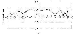
Fig. 6 shows with image height (mm) to be transverse axis, is the mean value of the normal angulation of the chief ray of 3 light beams on the sensitization magnetic drum surface 7 of the arbitrary scan position in the main sweep cross section of inciding present embodiment and this sensitization magnetic drum surface 7 the intersection point offset delta M of the main sweep on scanning position of β
(β)Curve map with curve representation.At this, carry out the image height that BD detects as the image height 114.1mm of the right-hand member of curve, the intersection point side-play amount here is δ M
(BD), this amount is 0.99047mm.
Fig. 7 is that the transverse axis of establishing above-mentioned curve is the figure of mean value β that incides the normal angulation of the chief ray of 3 light beams on the sensitization magnetic drum surface 7 of the scanning position arbitrarily in the main sweep cross section and this sensitization magnetic drum surface 7.At this, be to carry out the image height that BD detects as the angle beta of curve right-hand member at 28.78 degree, the intersection point side-play amount here is δ M
(BD), this amount is 0.99047mm.
Fig. 8 is mean value β, the above-mentioned δ M of the normal angulation of the scanning image height of the light beam on the sensitization magnetic drum surface 7 in the present embodiment, the chief ray that incides 3 light beams on the sensitization magnetic drum surface 7 of the scanning position arbitrarily in the main sweep cross section and sensitization magnetic drum surface 7
(β)Deng numeric data.
Fig. 9 be with β be transverse axis the value of the above-mentioned formula (3) of present embodiment, promptly on sensitization magnetic drum surface 7, carry out the offset delta Y of the image space of the main scanning direction in the effective scanning zone of image recording
FocusThe curve map of curveization.
In the present embodiment, the number of a plurality of luminescence units is 3, the mean value α that incides the normal angulation of the chief ray of 3 light beams on the sensitization magnetic drum surface 7 in the subscan cross section and sensitization magnetic drum surface 7 is 6 degree, and per 1 inch pixel count Ns of the sub scanning direction of determining according to the resolution of the sub scanning direction on the sensitization magnetic drum surface 7 is 600.Figure 10 is to be transverse axis with β, the value of the above-mentioned formula (5) by will be at this moment, the normal angulation that promptly incides the chief ray of 3 light beams on the sensitization magnetic drum surface 7 and sensitization magnetic drum surface 7 in the subscan cross section is set at the offset delta Y of the image space of the main scanning direction in the effective scanning zone that angle [alpha] produced that is not zero regulation
DThe curve map of curveization.
With the offset addition of the image space of Fig. 9 and main scanning direction shown in Figure 10, the amount of getting its absolute value is the left side of above-mentioned conditional (6),
[formula 21]
This amount
Value 25.4/3N with the right of above-mentioned conditional
MWith β be the transverse axis curveization curve map as shown in figure 11.
In the present embodiment, as shown in figure 11, by satisfying above-mentioned conditional (6), with the side-play amount of the image space that is suppressed at the main scanning direction in the effective scanning zone of carrying out image recording on the sensitization magnetic drum surface 7 effectively.Realize the multi-beam optical scanning apparatus of at a high speed suitable and high image quality thus.
In the present embodiment, by using the light supply apparatus in light supply apparatus, have the luminescence unit more than 3, realization can with the corresponding form of high speed more.If further increase the number of luminescence unit then favourable to further high speed.But, for the monolithic multi beam semiconductor laser that uses in the present embodiment, if set the interval of a plurality of luminescence units for a short time, then because of easy deteriorations of characteristic such as decay, crosstalks, so the interval of existing luminescence unit is 0.1mm mostly.Thereby the number of luminescence unit increases more, then above-mentioned S
1Value big more, δ Y
Focus, δ Y
DAmount increase easily, promptly the side-play amount of the image space of the main scanning direction in the effective scanning zone increases easily, be difficult to obtain images with high image quality output, but in the present embodiment, by satisfying the skew that above-mentioned conditional (6) reduces the image space of light beam, can obtain images with high image quality.Above-mentioned conditional (6) is in order to obtain in the number of the luminescence unit essential condition of the output of the images with high image quality under the situation more than 3 particularly.
And then, in the present embodiment, the formation that BD slit 9 is configured in front one side of BD lens 10 has been described, but not that BD slit 9 must be set in addition, also can omit BD lens 10, on the position in BD slit 9, promptly go up directly configuration as the BD sensor 11 that writes out the position synchronous signal detection component at the image space (position that is equivalent to sensitization magnetic drum 7) of each light beam.In this case, the end edge of the sensor of BD sensor 11 one side (sensitive surface) certainly plays the effect same with BD slit 9.
[embodiment 2]
Figure 12 is the main sweep sectional view of the multi-beam optical scanning apparatus of embodiments of the invention 2.In same figure, on the key element identical, marked prosign with key element shown in Figure 1.
Be with the foregoing description 1 difference in the present embodiment, constitute light supply apparatus 12 by 3 luminescence unit 1a, 1b, 1c, and by BD lens 13, BD slit 14, also have BD sensor 11 etc. to constitute to write out the position synchronous signal supervisory instrument, by satisfying the skew that conditional described later (11) reduces the image space of each light beam that penetrates from each luminescence unit 1a, 1b, 1c.Other formation and optical effect and embodiment 1 are roughly the same, can obtain same effect thus.
That is, in same figure, the 12nd, light supply apparatus has and have 3 luminescence unit 1a, 1b, 1c at interval on main scanning direction and sub scanning direction, for example is made of the multi beam semiconductor laser.And then, the description of omitting 3 luminescence unit 1a, 1b, 1c.At this, the number of luminescence unit is not limited to 3, also can be more than 4.
The 13rd, the imaging len (BD lens) as the synchronous detection of the 3rd optical system is used imports to BD sensor 11 to the BD light beam of reflection on light deflector 5.The 14th, slit (BD slit) is configured near the image space of BD lens 13 or its.
The multi-beam optical scanning apparatus of present embodiment is different with embodiment 1, be used to detect on the sensitization magnetic drum 7 the scanning starting position regularly write out the light beam (BD light beam) that the position synchronous input is used, its formation is to carry out the BD detection by another BD lens 13 that are used for the BD light beam by f θ lens 6 is not imported BD sensor 11.These BD lens 13 are by making imaging on the position in the BD slit 14 of deflection face 5a beam reflected in the main sweep cross section, and the anamorphic lens that makes deflection face 5a and BD slit 14 be in conjugate relation in the subscan cross section constitutes.
In the multi-beam optical scanning apparatus of present embodiment, because the BD light beam is by another BD lens 13 different with f θ lens 6, so even easily be interpreted as the intersection point skew δ M of the main sweep in the effective scanning zone of carrying out image recording on sensitization magnetic drum surface 7, the focal shift δ M of main sweep on the BD detection position
(BD)Be identical amount, the offset delta Y of the image space of main scanning direction
FocusAlso non-vanishing.
Present embodiment is the same with the above embodiments 1, and the mean value of the main beam of 3 light beams on the sensitization magnetic drum surface 7 that incides in the effective scanning zone of carrying out image recording on sensitization magnetic drum surface 7 and the normal angulation of this sensitization magnetic drum surface 7 is that the focus deviation of the locational main sweep of arbitrary scan of β is set to δ M
(β)Situation under, the offset delta Y of the image space of the main scanning direction of each light beam that penetrates from luminescence unit 1a, 1b, 1c on 7 of sensitization magnetic drums at this moment
1Can represent with following formula.
[formula 22]
In addition, if the focus deviation of the main sweep in scanning position of same each light beam during by BD slit 9 is set to δ M
(BD), the focal length of the main scanning direction of BD lens 13 is set to f
3, then this moment is from the offset delta Y of the image space of the main scanning direction on BD slit 9 of each light beam of luminescence unit 1a, 1b, 1c ejaculation
BDCan represent with following formula.
[formula 23]
Thereby present embodiment is the same with the above embodiments 1,
The focal length of collimation lens 2 is set to f
1
The distance of 5 deflection face 5a is set to L from diaphragm 3 to deflector
1
The focal length of the main scanning direction of f θ lens 6 is set to f
2
The intersection point distance of the main scanning direction of BD lens 13 is set to f
3
The mean value that incides the normal angulation of the chief ray of the light beam more than 3 on the sensitization magnetic drum surface 7 of the arbitrary scan position in the main sweep cross section and this sensitization magnetic drum surface 7 is that the focus deviation of the main sweep on the scanning position of β is set to δ M
(β)
On sensitization magnetic drum surface 7, carry out the offset delta Y of the image space of the main scanning direction in the effective scanning zone of image recording
FocusCan use following formulate.
[formula 24]
As seen from formula (9), in the present embodiment, even can be understood as the intersection point offset delta M of the main sweep in the effective scanning zone of on sensitization magnetic drum surface 7, carrying out image recording
(β), main sweep on the BD detection position focus deviation δ M
(BD)Be identical amount, the offset delta Y of the image space of main scanning direction
FocusAlso non-vanishing.
Below, the offset delta Y of the main scanning direction that produces because of the mean value α of the normal angulation of the chief ray that incides 3 light beams on the sensitization magnetic drum surface 7 in the subscan cross section and this sensitization magnetic drum surface 7
DThe same with the foregoing description 1, can represent with following formula.
[formula 25]
δ YD=Psin α tan β-Shi (10)
Thereby total absolute value of the offset delta Y of the image space of the main scanning direction on the sensitization magnetic drum surface 7 in the present embodiment is with the δ Y with formula (9) expression
FocusWith δ Y with formula (10) expression
DAmount after the addition can be represented with following formula.
[formula 26]
The offset of the imaging point of general main scanning direction basis is easily confirmed above 1/3 by the pel spacing of per 1 inch (25.4mm) of the definite main scanning direction of the resolution of the main scanning direction on the sensitization magnetic drum surface 7, can not ignore the influence of image.
Thereby, when the per 1 inch pixel count according to the definite main scanning direction of the resolution of the main scanning direction on the sensitization magnetic drum surface 7 is set to N
MThe time, above-mentioned δ Y must satisfy following conditional (11).
[formula 27]
In the present embodiment, establish:
The main scanning direction of luminescence unit 1a, 1b more than 3, luminescence unit 1a, the 1c at the two ends among the 1c be spaced apart S
1
The focal length of collimation lens 2 is f
1
The distance of deflection face 5a from this diaphragm 3 to deflector 5 is L
1
The focal length of the main scanning direction of f θ lens 6 is f
2
The focal length of the main scanning direction of BD lens 13 is f
3
The mean value that incides the normal angulation of the chief ray of 3 light beams of the sensitization magnetic drum surface 7 in the subscan cross section and this sensitization magnetic drum surface 7 is α;
Chief ray and this mean value that is scanned the normal angulation of face of inciding 3 light beams on the sensitization magnetic drum surface 7 of the arbitrary scan position in the main sweep cross section are β;
Focus deviation as the main sweep on the scanning position of this mean value β is δ M
(β)
As satisfy the above-mentioned formula (11), according to per 1 inch pixel count N of the main scanning direction of determining by the resolution of the main scanning direction on the sensitization magnetic drum surface 7
M, the imaging point of each light beam on sensitization magnetic drum surface 7 that penetrate from 3 luminescence unit 1a, 1b, 1c the interval P of sub scanning direction, above-mentioned respectively value is determined on optimum ground.
Thus, be suppressed at the side-play amount of the image space of the main scanning direction in the effective scanning zone of carrying out image recording on the sensitization magnetic drum surface 7 effectively, realize the multi-beam optical scanning apparatus of at a high speed suitable and high image quality thus.
Table 3, table 4 have been showed all characteristics of the multi-beam optical scanning apparatus of embodiments of the invention 2.
[table 3]
Table 3
| Use reference wavelength | λ | nm | 780 |
| Luminous counting | n | 3 | |
| Luminous point at interval | 1 | mm | 0.05000 |
| The luminous point at two ends at interval | S1 | mm | 0.10000 |
| Semiconductor laser cover glass thickness | dcg | mm | 0.25000 |
| Semiconductor laser cover glass refractive index | n0 | 1.51072 | |
| The 1st of luminous point~collimation lens | d0 | mm | 18.33000 |
| Collimation lens the 1st curvature of face radius | R1 | mm | ∞ |
| The collimation lens thickness | d1 | mm | 3.00000 |
| The collimation index of refraction in lens | n1 | 1.76203 | |
| Collimation lens the 2nd curvature of face radius | R2 | mm | -15.21639 |
| The 1st of the 1st~cylindrical lens of collimation lens | d2 | mm | 29.38200 |
| The 1st sub scanning direction radius-of-curvature of cylindrical lens | Rs3 | mm | 19.21300 |
| The 1st main scanning direction radius-of-curvature of cylindrical lens | Rm3 | mm | ∞ |
| Cylindrical lens thickness | d3 | mm | 3.00000 |
| The cylindrical lens refractive index | n3 | 1.52420 | |
| Cylindrical lens the 2nd curvature of face radius | R4 | mm | ∞ |
| The 2nd~unthreaded hole diaphragm of cylindrical lens | d4 | mm | 7.19000 |
| Unthreaded hole diaphragm~polygonal mirror deflection reflecting surface | d5(=L1) | mm | 28.36000 |
| The 1st of the polygonal mirror deflection surface of emission~1f θ lens | d6 | mm | 10.50000 |
| 1f θ lens thickness | d7 | mm | 6.50000 |
| The 1f θ index of refraction in lens | n7 | 1.52420 | |
| The 1st on the 2nd~2f θ lens of 1f θ lens | d8 | mm | 7.12000 |
| 2f θ lens thickness | d9 | mm | 6.60000 |
| The 2f θ index of refraction in lens | n9 | 1.52420 | |
| The 2nd on 2f θ lens~be scanned face | d10 | mm | 103.28000 |
| F θ lens main scanning direction focal length | f2 | mm | 109.00000 |
| Magnetic drum incident beam in subscan face and magnetic drum normal angulation | α | Degree | 10.00000 |
| Incident optical system polygonal mirror incident angle | γ | Degree | 85.00000 |
| Collimation lens focus distance | f1 | mm | 19.96823 |
| BD lens main scanning direction focal length | f3 | mm | 42.71700 |
| The polygonal mirror circumradius | r | mm | 10.00000 |
| The maximum scan angle | η | Degree | 56.24448 |
| The pixel count that main scanning direction is per 1 inch | Nm | 600 | |
| The pixel count that sub scanning direction is per 1 inch | Ns | 600 | |
| Polygonal mirror face number | men | 4 | |
[table 4]
Table 4
| F θ lens shape | |||
| 1f θ lens | |||
| The 1st | The 2nd | ||
| R | -26.48140 | R | -19.75260 |
| k | -1.49902E+00 | k | -8.11549E-01 |
| B4 | 2.62745E-05 | B4 | 1.30249E-05 |
| B6 | -5.63823E-08 | B6 | 3.59039E-03 |
| B8 | 0.00000E+00 | B8 | -9.03558E-11 |
| B10 | 0.00000E+00 | B10 | 0.00000E+00 |
| r | -11.60330 | r | -29.99770 |
| D2u | 1.66782E-02 | D2u | -4.74335E-02 |
| D4u | -2.05511E-05 | D4u | -7.89235E-04 |
| D6u | 0.00000E+00 | D6u | 5.72932E-06 |
| D8u | 0.00000E+00 | D8u | -9.37297E-09 |
| D10u | 0.00000E+00 | D10u | 0.00000E+00 |
| D21 | -9.72676E-05 | D21 | -1.03896E-02 |
| D41 | -7.39144E-06 | D41 | 8.82172E-05 |
| D61 | 0.00000E+00 | D61 | -3.60050E-07 |
| D81 | 0.00000E+00 | D81 | 5.30588E-10 |
| D101 | 0.00000E+00 | D101 | 0.00000E+00 |
| 2f θ lens | |||
| The 1st | The 2nd | ||
| R | 84.79910 | R | 82.56960 |
| k | -8.42997E+00 | k | -8.26049E-01 |
| B4u | -1.54001E-05 | B4u | -2.19243E-05 |
| B6u | 1.37412E-08 | B6u | 2.45322E-08 |
| B8u | -2.69944E-12 | B8u | -2.67301E-11 |
| B10u | -2.15513E-15 | B10u | 2.10166E-14 |
| B12u | 7.93243E-19 | B12u | -8.35950E-18 |
| B14u | 0.00000+00 | B14u | 1.04822E-21 |
| B41 | -1.71719E-05 | B41 | -2.31502E-05 |
| B61 | 1.72463E-08 | B61 | 2.67547E-08 |
| B81 | -4.67025E-12 | B81 | -2.92126E-11 |
| B101 | -1.99776E-15 | B101 | 2.29436E-14 |
| B121 | 7.71718E-19 | B121 | -8.50899E-18 |
| B141 | 0.00000E+00 | B141 | 6.12529E-22 |
| R | -78.88030 | r | -10.05710 |
| D2u | 4.13213E-02 | D2u | 1.77203E-03 |
| D4u | -3.82144E-05 | D4u | -4.56816E-06 |
| D6u | -1.21474E-08 | D6u | 6.29186E-09 |
| D8u | 2.14803E-11 | D8u | -4.13362E-12 |
| D10u | 0.00000E+00 | D10u | 1.05481E-15 |
| D21 | 0.00000E+00 | ||
| D41 | 0.00000E+00 | ||
| D61 | 0.00000E+00 | ||
| D81 | 0.00000E+00 | ||
| D101 | 0.00000E+00 | ||
And then, can represent the aspherical shape (busbar cross-section aspherical shape) in main sweep cross section of the f θ lens in the present embodiment and the shape (sub-line cross sectional shape) in subscan cross section with above-mentioned formula (a) and (b).
Figure 13 shows with image height (mm) be transverse axis, is the mean value of the normal angulation of the chief ray of 3 light beams on the sensitization magnetic drum surface 7 of the arbitrary scan position in the main sweep cross section of inciding present embodiment and this sensitization magnetic drum surface 7 the focus deviation δ M of the main sweep in the scanning position of β
(β)The curve map of curveization.
Figure 14 is that the mean value β with the normal angulation of the chief ray of 3 light beams on the sensitization magnetic drum surface 7 that incides the scanning position arbitrarily in the main sweep cross section and this sensitization magnetic drum surface 7 is the figure of the transverse axis of above-mentioned curve.
Figure 15 is mean value β, the above-mentioned δ M of the normal angulation of the scanning image height of the light beam on the sensitization magnetic drum surface 7 in the present embodiment, the chief ray that incides 3 light beams on the sensitization magnetic drum surface 7 of the arbitrary scan position in the main sweep cross section and sensitization magnetic drum surface 7
(β)Deng numeric data.
In addition, BD detects and the deflection face 5a beam reflected by light deflector 5 is set on the angle that reflects with 75 degree focus deviation δ M wherein
(BD)Be 0.3mm.
Figure 16 is to be transverse axis with β, the value of above-mentioned (9) formula of present embodiment, promptly carries out the offset delta Y of the image space of the main scanning direction in the effective scanning zone of image recording on sensitization magnetic drum surface 7
FocusThe curve map of curveization.
In the present embodiment, the number of a plurality of luminescence units is 3, the mean value α that incides the normal angulation of the chief ray of 3 light beams on the sensitization magnetic drum surface 7 in the subscan cross section and this sensitization magnetic drum surface 7 is 10 degree, and per 1 inch pixel count Ns of the sub scanning direction of determining according to the resolution of the sub scanning direction on the sensitization magnetic drum surface 7 is 600.Figure 17 shows with β to be transverse axis, by the value of at this moment above-mentioned formula (10), incide in the subscan cross section promptly that angle that the normal of the chief ray of 3 light beams on the sensitization magnetic drum surface 7 and this sensitization magnetic drum surface 7 forms is arranged to not to be that the angle of zero regulation produces, the offset delta Y of the image space of the main scanning direction on the effective scanning zone
DThe curve map of curveization.
The add offset addition of image space of Figure 16 and main scanning direction shown in Figure 17, the amount that obtains its absolute value is the left side of above-mentioned conditional (11),
[formula 28]
This amount
Value 25.4/3N with the right of above-mentioned conditional
MWith β be the transverse axis curveization figure as shown in figure 18.
In the present embodiment, as shown in figure 18,, can be suppressed at the offset delta Y of the image space of the main scanning direction in the effective scanning zone of carrying out image recording on the sensitization magnetic drum surface 7 effectively by satisfying above-mentioned conditional (11).Realize the multi-beam optical scanning apparatus of at a high speed suitable and high image quality thus.
And then, in the present embodiment, the formation that BD slit 14 is configured in the front of BD sensor 11 has been described, but not that BD slit 14 must be set in addition, also can on the position in BD slit 9, promptly go up directly configuration as the BD sensor 11 that writes out the position synchronous signal detection component at the image space (position that is equivalent to sensitization magnetic drum 7) of each light beam.In this case, the end edge of the sensor of BD sensor 11 one side (sensitive surface) certainly plays the function same with BD slit 9.
And then, in each above embodiment 1,2, as light supply apparatus 1 although understand to use the embodiment of 1 multi beam monolithic semiconductor laser, but the present invention is not limited to this, for example use the multi beam semiconductor laser, carry out the synthetic form of light beam with devices such as light beam synthetic prisms and also can be suitable for.
In this case, the interval S of the main scanning direction of luminescence unit 1a, the 1c at two ends
1, be taken at the S that has the situation of luminescence unit on the virtual image position with the synthetic front of the light beam synthetic prisms of each multi beam semiconductor laser
1Value be self-evident.
In addition, as monolithic semiconductor laser, the semiconductor laser that all disposes to 2 dimensions the surface-emitting type of luminescence units on the semiconductor laser of end face light emitting-type and main scanning direction and the sub scanning direction separatedly goes for the present invention.
In addition, constitute by the 1st, the 2nd f θ lens 6a, 2 lens of 6b as the imaging optical system 6 of the 2nd luminescent system, but the present invention is not limited to this with f θ characteristic.For example, also can be 1 lens, the lens more than 3, also can be the shape formula that curved reflector and diffraction optical element is combined as lens.
[embodiment 3]
Figure 19 is the main sweep sectional view of the multi-beam optical scanning apparatus of embodiments of the invention 3.In same figure, on the key element identical, mark duplicate numbers with staple shown in Figure 1.
Be with the foregoing description 1 difference in the present embodiment: BD slit 19 is arranged to can move along the direct of travel of the multiple beam that incides this BD slit 19.Other formations and optical effect and embodiment 1 are roughly the same, can obtain effect same thus.
That is, in same figure, the 19th, BD slit, the formation that formation can be moved along the direct of travel of the multi-beam that incides this BD slit 19.
In the present embodiment, the BD image height is because be set at the outside of image effective coverage, so the part that the BD light beam of f θ lens passes through is positioned at the end position of lens.Therefore, generally increase easily in the end mismachining tolerance especially, also be easy to generate focal shift in the man-hour that adds of f θ lens.
In addition, when the situation that forms f θ lens with plastic shaping etc. down, the performance that is easy to generate the lens end especially is discrete, also is easy to generate the focus deviation.
In the present embodiment, as mentioned above under the situation of the focal shift that produces the BD image height, move along the direct of travel of light beam, revise the offset delta Y of the image space of the main scanning direction on this BD slit 19 by make BD slit 19 according to this focus deviation
BD
Thus, be suppressed at the side-play amount of the main scanning direction image space in the effective scanning zone of carrying out image recording on the sensitization magnetic drum surface 7 effectively, realize the multi-beam optical scanner of at a high speed suitable and high image quality thus.
And then, in the present embodiment, the formation that BD slit 9 is configured in the front of BD lens 10 has been described, but BD slit 9 must be set in addition, also can omit BD lens 10, on the position in BD slit 9, promptly, the image space (position that is equivalent to sensitization magnetic drum surface 7) of each light beam goes up directly configuration BD sensor 11.In this case, the edge of the sensor cover end of BD sensor 11 plays the function same with BD slit 9.Under the situation of such formation, self move by making BD sensor 11 along the light beam direct of travel, can obtain same effect.
And then present embodiment can certainly be applicable in the above embodiments 2.
[embodiment 4]
Figure 20 is the enlarged drawing that writes out the position synchronous signal supervisory instrument of the multi-beam optical scanning apparatus of embodiments of the invention 4.In same figure, on the key element identical, marked same-sign with key element shown in Figure 1.
Difference with the foregoing description 1 is in the present embodiment: BD slit 29 is arranged in respect to rotary formation in the cross section of the direct of travel approximate vertical of the multiple beam that incides this BD slit 29.Other formation and optical effect and embodiment 1 are roughly the same, can obtain same effect thus.
That is, in same figure, the 29th, the BD slit, formation is with respect to rotary formation in the cross section of the direct of travel approximate vertical of the multiple beam that incides this slit 29.
Focal shift with respect to the BD image height described in the foregoing description 3, be arranged in the present embodiment revise the offset delta Y of the image space of the main scanning direction on this BD slit 29 in the cross section with respect to the direct of travel approximate vertical of the multiple beam that incides this BD slit 29 by BD slit 29 is rotated
BDFormation.
Thus, be suppressed at the side-play amount of the image space of the main scanning direction in the effective scanning zone of carrying out image recording on the sensitization magnetic drum surface 7 effectively, realize the multi-beam optical scanner of at a high speed suitable and high image quality thus.
And then, in the present embodiment, the formation that BD slit 9 is configured in the front of BD lens 10 has been described, but BD slit 9 must be set in addition, also can omit BD lens 10, on the position in BD slit 9, promptly, the image space (position that is equivalent to sensitization magnetic drum surface 7) of each light beam goes up directly configuration BD sensor 11.In this case, the edge of the sensor cover end of BD sensor 11 plays the function same with BD slit 9.Under the situation of such formation,, can obtain same effect by making BD sensor 11 from light beam direct of travel approximate vertical face, rotating.
And then present embodiment can certainly be applicable in the above embodiments 2.
(image processing system)
Figure 21 is the main sectional view of sub scanning direction of showing the embodiment of image processing system of the present invention.In the drawings, symbol 104 presentation videos form device.In this image processing system 104, from external mechanical such as personal computer 117 input code data Dc.This code data Dc is transformed to view data (point data) Di by the printer controller 111 in the device.This view data Di is imported into the multi-beam optical scanning apparatus 100 of the formation that one of has shown in the embodiment 1~4.Then, from the light beam 103 that this multi-beam optical scanning apparatus 100 penetrates according to view data Di modulation, on main scanning direction, scan the light-sensitive surface of sensitization magnetic drum 101 by this light beam 103.
Sensitization magnetic drum 101 as electrostatic latent image carrier (photoreceptor) is driven and is clockwise rotated by motor 115.Then, along with this rotates, the light-sensitive surface of sensitization magnetic drum 101 is with respect to light beam 103, with the sub scanning direction of main scanning direction quadrature on move.Above sensitization magnetic drum 101, the surface and the same charged charged roller 102 surface contacts that make sensitization magnetic drum 101 are set.Then, on the surface of the sensitization magnetic drum 101 charged by charged roller 102, irradiation is by the light beam 103 of above-mentioned multi-beam optical scanning apparatus 100 scannings.
As mentioned above, according to view data Di modulated beam of light 103, make the surface of sensitization magnetic drum 101 form electrostatic latent image by shining this light beam 103.By also contacting the imagescope 107 that is provided with like that with sensitization magnetic drum 101, this electrostatic latent image is looked like to carry out video picture as toner in downstream one side of the rotation direction of sensitization magnetic drum 101 than the irradiation position of above-mentioned light beam 103.
Below sensitization magnetic drum 101, the toners by imagescope 101 video pictures are looked like to be transferred to as being transferred on the paper 112 of material by being configured to the transfer printing roller relative 108 with sensitization magnetic drum 101.Paper 112 is incorporated in the carton 109 in the place ahead (right side among Figure 21) of sensitization magnetic drum 101, but also manual paper supply.On carton 109 ends, set paper supply roller 110, the paper 112 in the carton 109 is sent into transmitted the road.
Thus, transfer printing has the paper 112 of unfixing toner picture further to be arrived the fuser in sensitization magnetic drum 101 rears (left side among Figure 21) by conveyance.Fuser in inside by photographic fixing roller 113 be crimped on the pressure roller 114 that disposes like that on this photographic fixing roller 113 and constitute with fixing heater (not shown), from transfer printing unit conveyance next paper 112 pressurized and heating, the unfixing toner picture on the photographic fixing paper 112 thus on the crimping unit of photographic fixing roller 113 and pressure roller 114.And then set line paper rolling wheel 116 at the rear of photographic fixing roller 113, the paper 112 of photographic fixing is discharged to outside the image processing system.
Though it is not shown in Figure 21, but printer controller 111 does not just carry out the data conversion that illustrates previously, also comprises the control of polygonal mirror motor in each unit in interior image processing system of motor 115, the above-mentioned multi-beam optical scanning apparatus etc.
(coloured image formation device)
Figure 22 shows that coloured image of the present invention forms the major part skeleton diagram of the embodiment of device.Present embodiment is 4 multi-beam optical scanning apparatus of parallel arranged, forms device at the compound coloured image as recording image information on as the sensitization magnetic drum surface of supporting body.In Figure 22, the 60th, coloured image forms device, 61, the 62,63, the 64th, one of have shown in each embodiment 1~4 multi-beam optical scanning apparatus that constitutes, the 21,22,23, the 24th, as the sensitization magnetic drum of various picture supporting bodies, the 32,32,33, the 34th, each imagescope, the 51st, conveying belt.And then, in Figure 22, have the toner of video picture in imagescope look like to be transferred to the transfer printing device (not shown) that is transferred on the material, the toner that is transferred as photographic fixing in the fuser (not shown) that is transferred on the material.
In Figure 22, form each color signal of device 60 input R (red), G (green), B (indigo plant) to coloured image from external mechanical such as personal computer 52.These color signals are transformed to each view data (point data) of C (blue-green), M (fuchsin), Y (Huang), B (deceiving) by the printer controller 53 in the device.These view data are input to multi-beam optical scanning apparatus 61,62,63,64 respectively.Then, penetrate the light beam of modulating according to each view data 41,42,43,44, by the sensitization magnetic drum surface of these light beams at main scanning direction scanning sensitization magnetic drum 21,22,23,24 from these multi-beam optical scanning apparatus.
Coloured image in the present embodiment forms device and arranges 4 multi-beam optical scanning apparatus (61,62,63,64), corresponding with each color of C (blue-green), M (fuchsin), Y (Huang), B (deceiving) separately, recording image signal (image information) on 21,22,23,24 of sensitization magnetic drums abreast separately, the high speed printing coloured image.
Coloured image in the present embodiment forms device as mentioned above, use light beam by 4 multi-beam optical scanning apparatus 61,62,63,64, the sub-image of each color is formed on 21,22,23,24 of the sensitization magnetic drums corresponding with each based on each view data.Thereafter, multiple transfer printing forms the image of 1 full color on recording materials.
As said external machine 52, also can use to possess for example color image reader of ccd sensor.In this case, form device 60 by this color image reader, coloured image and constitute color digital copying machine.
If employing the present invention, then by the value of setting each key element aptly feasible satisfy condition formula (6) or conditional (11), do not need complicated adjustment just can reduce the skew of the image space of many light beams that penetrate from light supply apparatus effectively, can be suitable for high speed and the multi-beam optical scanning apparatus of high image quality and the image processing system that uses it thus with a plurality of luminescence units.
Claims (21)
1, a kind of multi-beam optical scanning apparatus is to comprise the light supply apparatus that has having the luminescence unit more than 3 or 3 at interval on main scanning direction and the sub scanning direction; The state of the divergent beams more than 3 or 3 that will penetrate from this light supply apparatus is changed into the 1st optical system of other state; The diaphragm of the width of light beam of the main scanning direction at least of the light beam more than 3 or 3 of restricted passage the 1st optical system; Reflection is by the polygonal rotating mirror of the light beam more than 3 or 3 of this diaphragm; Be scanned on the face the 2nd optical system that is imaged as imaging point at the light beam more than 3 or 3 that reflects on this polygonal rotating mirror; Detect the multi-beam optical scanning apparatus that writes out the position synchronous signal supervisory instrument of the timing signal of this scanning starting position that is scanned the imaging point on the face, it is characterized in that:
This writes out the position synchronous signal supervisory instrument has and writes out the position synchronous signal detection component, is configured in the slot-shaped parts between this light path of writing out position synchronous signal detection component and this polygonal rotating mirror,
This writes out the position synchronous signal supervisory instrument and writes out the light beam that the position synchronous signal detection component detects on this polygonal rotating mirror reflection and passed through the 2nd optical system by this, and detects the timing signal that this is scanned the scanning starting position on the face,
The S that is set to that leaves main scanning direction between farthest the luminescence unit in this luminescence unit more than 3 or 3
1
The focal length of the 1st optical system is set to f
1
The distance of the deflection face from this diaphragm to this polygonal rotating mirror is set to L
1
The focal length of the main scanning direction of the 2nd optical system is set to f
2
Incide this chief ray that is scanned the light beam more than 3 or 3 on the face and be set to α with the mean value of angle that this is scanned the sub scanning direction that normal became of face;
The chief ray that this that incides the arbitrary scan position is scanned the light beam more than 3 or 3 on the face is set to β with the mean value of angle that this is scanned the main scanning direction that normal became of face;
Focus deviation as the main scanning direction in the scanning position of this mean value β is set to δ M
(β)
The focus deviation of the main scanning direction in the scanning position of these 3 light beams more than 3 during by these slot-shaped parts is set to δ M
(BD)
Per 1 inch pixel count according to the definite main scanning direction of the resolution that is scanned the main scanning direction on the face at this is set to N
M
From this luminescence unit more than 3 or 3 leave 2 light beams that luminescence unit farthest penetrates this be scanned the imaging point on the face sub scanning direction be set to P the time, satisfy the condition of following formula:
Wherein, δ M
(β), δ M
(BD)Be defined as from being configured in the focus deviation of the light beam that penetrates with the nearest locational luminescence unit of the optical axis of the 1st optical system.
2, a kind of multi-beam optical scanning apparatus is to comprise the light supply apparatus that has having the luminescence unit more than 3 or 3 at interval on main scanning direction and the sub scanning direction; The state of the divergent beams more than 3 or 3 that will penetrate from this light supply apparatus is changed into the 1st optical system of other state; The diaphragm of the width of light beam of the main scanning direction at least of the light beam more than 3 or 3 of restricted passage the 1st optical system; Reflection is by the polygonal rotating mirror of the light beam more than 3 or 3 of this diaphragm; Be scanned on the face the 2nd optical system that is imaged as imaging point at the light beam more than 3 or 3 that reflects on this polygonal rotating mirror; Detect the multi-beam optical scanning apparatus that writes out the position synchronous signal supervisory instrument of the timing signal of this scanning starting position that is scanned the imaging point on the face, it is characterized in that:
This write out that the position synchronous signal supervisory instrument has and the 2nd optical system independently the 3rd optical system, write out the position synchronous signal detection component, be configured in the slot-shaped parts between this light path of writing out position synchronous signal detection component and the 3rd optical system,
This writes out the position synchronous signal supervisory instrument and writes out the light beam that the position synchronous signal detection component detects on this polygonal rotating mirror reflection and passed through the 3rd optical system by this, and detect the timing signal that this is scanned the scanning starting position of the imaging point on the face
The S that is set to that leaves main scanning direction between farthest the luminescence unit in this luminescence unit more than 3 or 3
1
The focal length of the 1st optical system is set to f
1
The distance of the deflection face from this diaphragm to this polygonal rotating mirror is set to L
1
The focal length of the main scanning direction of the 2nd optical system is set to f
2
The focal length of the main scanning direction of the 3rd optical system is set to f
3
Incide this chief ray that is scanned the light beam more than 3 or 3 on the face and be set to α with the mean value of angle that this is scanned the sub scanning direction that normal became of face;
The chief ray that this that incides the arbitrary scan position is scanned the light beam more than 3 or 3 on the face is set to β with the mean value of angle that this is scanned the main scanning direction that normal became of face;
Focus deviation as the main scanning direction in the scanning position of this mean value β is set to δ M
(β)
The focus deviation of the main scanning direction in the scanning position of this light beam more than 3 or 3 during by these slot-shaped parts is set to δ M
(BD)
Per 1 inch pixel count according to the definite main scanning direction of the resolution that is scanned the main scanning direction on the face at this is set to N
M
From these 3 or 3 above luminescence units leave 2 light beams that luminescence unit farthest penetrates this be scanned the imaging point on the face sub scanning direction be set to P the time, satisfy the condition of following formula:
Wherein, δ M
(β), δ M
(BD)Be defined as from being configured in the focus deviation of the light beam that penetrates with the nearest locational luminescence unit of the optical axis of the 1st optical system.
3, multi-beam optical scanning apparatus according to claim 1, it is characterized in that: the above-mentioned position synchronous signal supervisory instrument that writes out uses whole by the light beam more than 3 or 3 of above-mentioned rotating multisurface mirror reflection, controls the above-mentioned timing that is scanned the scanning starting position on the face.
4, multi-beam optical scanning apparatus according to claim 2, it is characterized in that: the above-mentioned position synchronous signal supervisory instrument that writes out uses whole by the light beam more than 3 or 3 of above-mentioned rotating multisurface mirror reflection, controls the above-mentioned timing that is scanned the scanning starting position on the face.
5, multi-beam optical scanning apparatus according to claim 1 is characterized in that: above-mentioned slot-shaped parts can move along the direct of travel that incides the light beam more than 3 or 3 in these slot-shaped parts.
6, multi-beam optical scanning apparatus according to claim 2 is characterized in that: above-mentioned slot-shaped parts can move along the direct of travel that incides the light beam more than 3 or 3 in these slot-shaped parts.
7, multi-beam optical scanning apparatus according to claim 1 is characterized in that: above-mentioned slot-shaped parts can rotate in the cross section with respect to the direct of travel approximate vertical of the light beam more than 3 or 3 that incides these slot-shaped parts.
8, multi-beam optical scanning apparatus according to claim 2 is characterized in that: above-mentioned slot-shaped parts can rotate in the cross section with respect to the direct of travel approximate vertical of the light beam more than 3 or 3 that incides these slot-shaped parts.
9, multi-beam optical scanning apparatus according to claim 1 is characterized in that: what reflect on above-mentioned polygonal rotating mirror incides the above-mentioned light beam of position synchronous signal detection component that writes out by the 2nd optical system.
10, a kind of image processing system is characterized in that comprising: any 1 described multi-beam optical scanning apparatus of claim 1 to 9; Be configured in the above-mentioned photoreceptor that is scanned on the face; By light beam by the scanning of above-mentioned multi-beam optical scanning apparatus, the electrostatic latent image that is formed on the above-mentioned photoreceptor is looked like to carry out video picture as toner imagescope; The toner that is rasterized is looked like to be transferred to the transfer printing device that is transferred on the material; The toner that is transferred as photographic fixing in the fuser that is transferred on the material.
11, a kind of image processing system is characterized in that comprising:
Any 1 described multi-beam optical scanning apparatus of claim 1~9;
Printer controller, it is transformed to picture signal to the code data from the external mechanical input, is input to above-mentioned multi-beam optical scanning apparatus.
12, a kind of coloured image forms device, it is characterized in that comprising: be configured in being scanned on the face of any 1 described multi-beam optical scanning apparatus of claim 1 to 9 separately, form a plurality of picture supporting bodies of the image of mutual different colours.
13, the described coloured image of claim 12 forms device, it is characterized in that also comprising: printer controller, it is transformed to the view data of different colours to the color signal from the external mechanical input, and is input to each multi-beam optical scanning apparatus.
14, a kind of multi-beam optical scanning apparatus is to comprise the light supply apparatus that has having the luminescence unit more than 3 or 3 at interval on main scanning direction and the sub scanning direction; The state of the divergent beams more than 3 or 3 that will penetrate from this light supply apparatus is changed into the 1st optical system of other state; The diaphragm of the width of light beam of the main scanning direction at least of the light beam more than 3 or 3 of restricted passage the 1st optical system; Reflection is by the polygonal rotating mirror of the light beam more than 3 or 3 of this diaphragm; Be scanned on the face the 2nd optical system that is imaged as imaging point at the light beam more than 3 or 3 that reflects on this polygonal rotating mirror; Detect the multi-beam optical scanning apparatus that writes out the position synchronous signal supervisory instrument of the timing signal of this scanning starting position that is scanned the imaging point on the face, it is characterized in that:
This writes out the position synchronous signal supervisory instrument and has the position synchronous of writing out signal detection component,
This writes out the position synchronous signal supervisory instrument and writes out the light beam that the position synchronous signal detection component detects on this polygonal rotating mirror reflection and passed through the 2nd optical system by this, and detects the timing signal that this is scanned the scanning starting position on the face,
The S that is set to that leaves main scanning direction between farthest the luminescence unit in this luminescence unit more than 3 or 3
1
The focal length of the 1st optical system is set to f
1
The distance of the deflection face from this diaphragm to this polygonal rotating mirror is set to L
1
The focal length of the main scanning direction of the 2nd optical system is set to f
2
Incide this chief ray that is scanned the light beam more than 3 or 3 on the face and be set to α with the mean value of angle that this is scanned the sub scanning direction that normal became of face;
The chief ray that this that incides the arbitrary scan position is scanned the light beam more than 3 or 3 on the face is set to β with the mean value of angle that this is scanned the main scanning direction that normal became of face;
Focus deviation as the main scanning direction in the scanning position of this mean value β is set to δ M
(β)
This light beam more than 3 or 3 is set to δ M at the focus deviation that this writes out the main scanning direction in the sensitive surface of position synchronous signal detection component
(BD)
Per 1 inch pixel count of the main scanning direction of determining according to this resolution that is scanned the main scanning direction on the face is set to N
M
From this luminescence unit more than 3 or 3 leave 2 light beams that luminescence unit farthest penetrates this be scanned the imaging point on the face sub scanning direction be set to P the time, satisfy the condition of following formula:
Wherein, δ M
(β), δ M
(BD)Be defined as from being configured in the focus deviation of the light beam that penetrates with the nearest locational luminescence unit of the optical axis of the 1st optical system.
15, a kind of multi-beam optical scanning apparatus is to comprise the light supply apparatus that has having the luminescence unit more than 3 or 3 at interval on main scanning direction and the sub scanning direction; The state of the divergent beams more than 3 or 3 that will penetrate from this light supply apparatus is changed into the 1st optical system of other state; The diaphragm of the width of light beam of the main scanning direction at least of the light beam more than 3 or 3 of restricted passage the 1st optical system; Reflection is by the polygonal rotating mirror of the light beam more than 3 or 3 of this diaphragm; Be scanned on the face the 2nd optical system that is imaged as imaging point at the light beam more than 3 or 3 that reflects on this polygonal rotating mirror; Detect the multi-beam optical scanning apparatus that writes out the position synchronous signal supervisory instrument of the timing signal of this scanning starting position that is scanned the imaging point on the face, it is characterized in that:
This write out the position synchronous signal supervisory instrument have with the 2nd optical system independently the 3rd optical system, write out the position synchronous signal detection component,
This writes out the position synchronous signal supervisory instrument and writes out the light beam that the position synchronous signal detection component detects on this polygonal rotating mirror reflection and passed through the 3rd optical system by this, and detects the timing signal that this is scanned the scanning starting position on the face,
The S that is set to that leaves main scanning direction between farthest the luminescence unit in this luminescence unit more than 3 or 3
1
The focal length of the 1st optical system is set to f
1
The distance of the deflection face from this diaphragm to this polygonal rotating mirror is set to L
1
The focal length of the main scanning direction of the 2nd optical system is set to f
2
The focal length of the main scanning direction of the 3rd optical system is set to f
3
Incide this chief ray that is scanned the light beam more than 3 or 3 on the face and be set to α with the mean value of angle that this is scanned the sub scanning direction that normal became of face;
The chief ray that this that incides the arbitrary scan position is scanned the light beam more than 3 or 3 on the face is set to β with the mean value of angle that this is scanned the main scanning direction that normal became of face;
Focus deviation as the main scanning direction in the scanning position of this mean value β is set to δ M
(β)
This light beam more than 3 or 3 is set to δ M at the focus deviation that this writes out the main scanning direction in the sensitive surface of position synchronous signal detection component
(BD)
Per 1 inch pixel count according to the definite main scanning direction of the resolution that is scanned the main scanning direction on the face at this is set to N
M
From this luminescence unit more than 3 or 3 leave 2 light beams that luminescence unit farthest penetrates this be scanned the imaging point on the face sub scanning direction be set to P the time, satisfy the condition of following formula:
Wherein, δ M
(β), δ M
(BD)Be defined as from being configured in the focus deviation of the light beam that penetrates with the nearest locational luminescence unit of the optical axis of the 1st optical system.
16, multi-beam optical scanning apparatus according to claim 14, it is characterized in that: the above-mentioned position synchronous signal supervisory instrument that writes out uses whole at the light beam more than 3 or 3 that reflects on the above-mentioned polygonal rotating mirror, controls the above-mentioned timing that is scanned the scanning starting position on the face.
17, multi-beam optical scanning apparatus according to claim 14 is characterized in that: pass through the 2nd optical system at the above-mentioned light beam that writes out on the position synchronous signal detection component that incides that reflects on the above-mentioned polygonal rotating mirror.
18, a kind of image processing system is characterized in that comprising: any 1 described multi-beam optical scanning apparatus of claim 14 to 17; Be configured in the above-mentioned photoreceptor that is scanned on the face; By light beam by the scanning of above-mentioned multi-beam optical scanning apparatus, the electrostatic latent image that is formed on the above-mentioned photoreceptor is looked like to carry out video picture as toner imagescope; The toner that is rasterized is looked like to be transferred to the transfer printing device that is transferred on the material; The toner that is transferred as photographic fixing in the fuser that is transferred on the material.
19, a kind of image processing system is characterized in that comprising: the described multi-beam optical scanning apparatus of claim 14~17; Printer controller, it is transformed to picture signal to the code data from the external mechanical input, is input in the above-mentioned multi-beam optical scanning apparatus.
20, a kind of coloured image forms device, it is characterized in that comprising: be configured in being scanned on the face of any 1 described multi-beam optical scanning apparatus of claim 14 to 17 separately, form a plurality of picture supporting bodies of the image of mutual different colours.
21, the described coloured image of claim 20 forms device, it is characterized in that also comprising: printer controller, it is transformed to the view data of different colours to the color signal from the external mechanical input and is input to each multi-beam optical scanning apparatus.
Applications Claiming Priority (4)
| Application Number | Priority Date | Filing Date | Title |
|---|---|---|---|
| JP2003312843 | 2003-09-04 | ||
| JP312843/2003 | 2003-09-04 | ||
| JP065790/2004 | 2004-03-09 | ||
| JP2004065790A JP4378193B2 (en) | 2003-09-04 | 2004-03-09 | Multi-beam optical scanning apparatus and image forming apparatus using the same |
Publications (2)
| Publication Number | Publication Date |
|---|---|
| CN1591081A CN1591081A (en) | 2005-03-09 |
| CN1300621C true CN1300621C (en) | 2007-02-14 |
Family
ID=34228022
Family Applications (1)
| Application Number | Title | Priority Date | Filing Date |
|---|---|---|---|
| CNB2004100319066A Expired - Fee Related CN1300621C (en) | 2003-09-04 | 2004-03-31 | Multi-beam optical scanning apparatus, and image forming apparatus using the same |
Country Status (3)
| Country | Link |
|---|---|
| US (1) | US7119824B2 (en) |
| JP (1) | JP4378193B2 (en) |
| CN (1) | CN1300621C (en) |
Families Citing this family (15)
| Publication number | Priority date | Publication date | Assignee | Title |
|---|---|---|---|---|
| JP4324019B2 (en) * | 2004-06-02 | 2009-09-02 | キヤノン株式会社 | Optical scanning device and image forming apparatus using the same |
| JP4819392B2 (en) * | 2005-04-28 | 2011-11-24 | キヤノン株式会社 | Scanning optical device and image forming apparatus using the same |
| JP4810354B2 (en) * | 2006-08-24 | 2011-11-09 | キヤノン株式会社 | Optical scanning device and scanning image display device |
| JP4836267B2 (en) * | 2007-02-22 | 2011-12-14 | 株式会社リコー | Optical scanning apparatus and image forming apparatus |
| US7877003B2 (en) * | 2007-06-20 | 2011-01-25 | Microscan Systems, Inc. | Devices, systems, and methods regarding images |
| JP4883795B2 (en) * | 2007-06-28 | 2012-02-22 | キヤノン株式会社 | Multi-beam optical scanning device and image forming apparatus using the same |
| US8248679B2 (en) * | 2007-08-21 | 2012-08-21 | Prsym, Inc. | Multibeam scanning device |
| JP5566068B2 (en) * | 2009-09-14 | 2014-08-06 | キヤノン株式会社 | Optical scanning device and image forming apparatus having the same |
| US8654165B2 (en) * | 2010-06-23 | 2014-02-18 | Ricoh Company, Limited | Optical scanning device and image forming apparatus |
| JP6049502B2 (en) * | 2013-02-28 | 2016-12-21 | キヤノン株式会社 | Optical scanning device and image forming apparatus using the same |
| JP6214204B2 (en) | 2013-05-09 | 2017-10-18 | キヤノン株式会社 | Optical scanning device, manufacturing method thereof, and image forming apparatus |
| JP5903406B2 (en) | 2013-06-28 | 2016-04-13 | 京セラドキュメントソリューションズ株式会社 | Light beam sensor position adjustment method |
| CN105044907B (en) * | 2015-07-13 | 2018-01-30 | 中国电子科技集团公司第五十研究所 | Rapid scanning delay line based on spiral step speculum |
| CN108369342B (en) * | 2015-12-10 | 2020-10-02 | 株式会社理光 | Optical scanning apparatus, image display apparatus, and vehicle |
| WO2022046059A1 (en) * | 2020-08-27 | 2022-03-03 | Hewlett-Packard Development Company, L.P. | Recommended page size determination |
Citations (4)
| Publication number | Priority date | Publication date | Assignee | Title |
|---|---|---|---|---|
| US6388791B2 (en) * | 2000-03-17 | 2002-05-14 | Hitachi Koki Co., Ltd. | Optical scanner |
| US6473215B1 (en) * | 1999-09-17 | 2002-10-29 | Hitachi Koki Co., Ltd. | Optical scanner |
| US6489982B2 (en) * | 1999-12-10 | 2002-12-03 | Canon Kabushiki Kaisha | Error reduction in a multi-beam scanning optical system, and image-forming apparatus using the same |
| US6590688B2 (en) * | 2000-05-25 | 2003-07-08 | Canon Kabushiki Kaisha | Optical scanning apparatus and image forming apparatus using the same |
Family Cites Families (14)
| Publication number | Priority date | Publication date | Assignee | Title |
|---|---|---|---|---|
| JPH05333281A (en) | 1992-05-29 | 1993-12-17 | Fuji Xerox Co Ltd | Image forming device |
| JP3367313B2 (en) | 1996-01-17 | 2003-01-14 | 富士ゼロックス株式会社 | Optical scanning device |
| JPH09304714A (en) * | 1996-05-10 | 1997-11-28 | Canon Inc | Optical scanner |
| JP3466863B2 (en) * | 1996-12-19 | 2003-11-17 | キヤノン株式会社 | Scanning optical device and image recording device using the same |
| JP3397624B2 (en) * | 1996-12-19 | 2003-04-21 | キヤノン株式会社 | Scanning optical device and laser beam printer having the same |
| US6067106A (en) * | 1997-04-16 | 2000-05-23 | Canon Kabushiki Kaisha | Scanning optical apparatus |
| US6317244B1 (en) * | 1998-12-17 | 2001-11-13 | Canon Kabushiki Kaisha | Light-scanning optical system and image-forming apparatus comprising the same |
| US6362470B1 (en) * | 1999-01-26 | 2002-03-26 | Canon Kabushiki Kaisha | Optical scanning apparatus and image forming apparatus and electrophotographic printer using such scanning apparatus |
| US6256132B1 (en) * | 1999-06-16 | 2001-07-03 | Canon Kabushiki Kaisha | Multi-beam scanning optical system and image forming apparatus using the same |
| JP4541523B2 (en) | 2000-10-10 | 2010-09-08 | キヤノン株式会社 | Multi-beam optical scanning optical system, multi-beam optical scanning device, and image forming apparatus |
| JP2002287057A (en) | 2001-03-27 | 2002-10-03 | Canon Inc | Multibeam scanning optical system and image forming device using it |
| JP4115104B2 (en) | 2001-06-29 | 2008-07-09 | キヤノン株式会社 | Multi-beam scanning optical system and image forming apparatus using the same |
| JP3667286B2 (en) * | 2002-02-20 | 2005-07-06 | キヤノン株式会社 | Optical scanning apparatus, image forming apparatus, and color image forming apparatus |
| JP2004302062A (en) * | 2003-03-31 | 2004-10-28 | Canon Inc | Multibeam light scanner |
-
2004
- 2004-03-09 JP JP2004065790A patent/JP4378193B2/en not_active Expired - Fee Related
- 2004-03-26 US US10/809,445 patent/US7119824B2/en not_active Expired - Fee Related
- 2004-03-31 CN CNB2004100319066A patent/CN1300621C/en not_active Expired - Fee Related
Patent Citations (4)
| Publication number | Priority date | Publication date | Assignee | Title |
|---|---|---|---|---|
| US6473215B1 (en) * | 1999-09-17 | 2002-10-29 | Hitachi Koki Co., Ltd. | Optical scanner |
| US6489982B2 (en) * | 1999-12-10 | 2002-12-03 | Canon Kabushiki Kaisha | Error reduction in a multi-beam scanning optical system, and image-forming apparatus using the same |
| US6388791B2 (en) * | 2000-03-17 | 2002-05-14 | Hitachi Koki Co., Ltd. | Optical scanner |
| US6590688B2 (en) * | 2000-05-25 | 2003-07-08 | Canon Kabushiki Kaisha | Optical scanning apparatus and image forming apparatus using the same |
Also Published As
| Publication number | Publication date |
|---|---|
| US20050052525A1 (en) | 2005-03-10 |
| JP2005099673A (en) | 2005-04-14 |
| JP4378193B2 (en) | 2009-12-02 |
| CN1591081A (en) | 2005-03-09 |
| US7119824B2 (en) | 2006-10-10 |
Similar Documents
| Publication | Publication Date | Title |
|---|---|---|
| CN1211685C (en) | Optical scanning equipment and imaging device with the same optical scanning equipment | |
| CN1300621C (en) | Multi-beam optical scanning apparatus, and image forming apparatus using the same | |
| CN1154338C (en) | Multi-beam exposure unit | |
| CN1265227C (en) | Optical imaging system and reader therewith | |
| CN1268993C (en) | Printing device and its control method | |
| CN1124020C (en) | Light beam scanner for imaging device | |
| CN1223170C (en) | Method for correcting colour image data by correction table | |
| CN1158846C (en) | Light-beam. scanner and imaging device | |
| CN1769948A (en) | Optical scanning apparatus and method for adjusting the same | |
| CN1585454A (en) | Lighting device, image reading apparatus , and image forming apparatus | |
| CN1707457A (en) | Data transfer method and data transfer device | |
| CN101055460A (en) | Image forming apparatus | |
| CN1155669A (en) | Optical scanning device and scanning lens therefor | |
| CN1239940C (en) | Optical scanner and imaging device thereof | |
| CN1794037A (en) | Optical scanning device and image display apparatus using the same | |
| CN1845014A (en) | Color image forming apparatus | |
| CN1977205A (en) | Zoom lens system, imaging device, and camera | |
| CN1276286C (en) | Optical scan device and imaging forming device using the device | |
| CN1208867A (en) | Method and device for evaluating light rays characteristic and device for regulating its writing unit | |
| CN1384385A (en) | Image reading imaging optical system and image reading device with the optical system | |
| CN1154341C (en) | Multi-light beam exposing device | |
| CN1210994A (en) | Optical writing head driving device and optical writing head driving method | |
| CN1123202C (en) | Light-beam scanner and image forming device | |
| CN101034205A (en) | Optical scanning apparatus and image forming apparatus using the same | |
| CN100351668C (en) | Multiple light beam scanner and imaging device, colour picture forming device |
Legal Events
| Date | Code | Title | Description |
|---|---|---|---|
| C06 | Publication | ||
| PB01 | Publication | ||
| C10 | Entry into substantive examination | ||
| SE01 | Entry into force of request for substantive examination | ||
| C14 | Grant of patent or utility model | ||
| GR01 | Patent grant | ||
| CF01 | Termination of patent right due to non-payment of annual fee |
Granted publication date: 20070214 Termination date: 20150331 |
|
| EXPY | Termination of patent right or utility model |