CN1299514A - Color cathode-ray tube device - Google Patents
Color cathode-ray tube device Download PDFInfo
- Publication number
- CN1299514A CN1299514A CN99805658A CN99805658A CN1299514A CN 1299514 A CN1299514 A CN 1299514A CN 99805658 A CN99805658 A CN 99805658A CN 99805658 A CN99805658 A CN 99805658A CN 1299514 A CN1299514 A CN 1299514A
- Authority
- CN
- China
- Prior art keywords
- mentioned
- phosphor screen
- deflection
- track correction
- bundle
- Prior art date
- Legal status (The legal status is an assumption and is not a legal conclusion. Google has not performed a legal analysis and makes no representation as to the accuracy of the status listed.)
- Granted
Links
- 238000012937 correction Methods 0.000 claims abstract description 151
- OAICVXFJPJFONN-UHFFFAOYSA-N Phosphorus Chemical compound [P] OAICVXFJPJFONN-UHFFFAOYSA-N 0.000 claims abstract description 100
- 238000010894 electron beam technology Methods 0.000 claims abstract description 71
- 239000011521 glass Substances 0.000 claims description 42
- 230000000694 effects Effects 0.000 claims description 18
- 230000001360 synchronised effect Effects 0.000 claims description 16
- 238000000576 coating method Methods 0.000 claims description 12
- 239000011248 coating agent Substances 0.000 claims description 11
- 238000005266 casting Methods 0.000 claims description 10
- 230000015572 biosynthetic process Effects 0.000 claims description 9
- 230000007812 deficiency Effects 0.000 claims description 4
- 230000002093 peripheral effect Effects 0.000 abstract description 4
- 230000015556 catabolic process Effects 0.000 abstract 1
- 238000006731 degradation reaction Methods 0.000 abstract 1
- 230000006866 deterioration Effects 0.000 description 36
- 241000226585 Antennaria plantaginifolia Species 0.000 description 11
- 238000010586 diagram Methods 0.000 description 11
- 230000033228 biological regulation Effects 0.000 description 9
- 230000004075 alteration Effects 0.000 description 8
- 238000000034 method Methods 0.000 description 5
- 206010010071 Coma Diseases 0.000 description 4
- 238000005516 engineering process Methods 0.000 description 4
- 238000007493 shaping process Methods 0.000 description 4
- 238000006073 displacement reaction Methods 0.000 description 3
- 230000005764 inhibitory process Effects 0.000 description 3
- 244000007853 Sarothamnus scoparius Species 0.000 description 2
- 230000009471 action Effects 0.000 description 2
- 230000008859 change Effects 0.000 description 2
- 229920006395 saturated elastomer Polymers 0.000 description 2
- 239000012141 concentrate Substances 0.000 description 1
- 239000012467 final product Substances 0.000 description 1
- 239000000463 material Substances 0.000 description 1
- 238000000465 moulding Methods 0.000 description 1
- 230000003287 optical effect Effects 0.000 description 1
- 238000001259 photo etching Methods 0.000 description 1
- 239000011295 pitch Substances 0.000 description 1
- 230000008569 process Effects 0.000 description 1
- 230000007704 transition Effects 0.000 description 1
Images


Classifications
-
- H—ELECTRICITY
- H01—ELECTRIC ELEMENTS
- H01J—ELECTRIC DISCHARGE TUBES OR DISCHARGE LAMPS
- H01J29/00—Details of cathode-ray tubes or of electron-beam tubes of the types covered by group H01J31/00
- H01J29/46—Arrangements of electrodes and associated parts for generating or controlling the ray or beam, e.g. electron-optical arrangement
- H01J29/70—Arrangements for deflecting ray or beam
- H01J29/72—Arrangements for deflecting ray or beam along one straight line or along two perpendicular straight lines
- H01J29/76—Deflecting by magnetic fields only
-
- H—ELECTRICITY
- H01—ELECTRIC ELEMENTS
- H01J—ELECTRIC DISCHARGE TUBES OR DISCHARGE LAMPS
- H01J29/00—Details of cathode-ray tubes or of electron-beam tubes of the types covered by group H01J31/00
- H01J29/46—Arrangements of electrodes and associated parts for generating or controlling the ray or beam, e.g. electron-optical arrangement
- H01J29/70—Arrangements for deflecting ray or beam
- H01J29/701—Systems for correcting deviation or convergence of a plurality of beams by means of magnetic fields at least
- H01J29/702—Convergence correction arrangements therefor
- H01J29/705—Dynamic convergence systems
-
- H—ELECTRICITY
- H01—ELECTRIC ELEMENTS
- H01J—ELECTRIC DISCHARGE TUBES OR DISCHARGE LAMPS
- H01J2229/00—Details of cathode ray tubes or electron beam tubes
- H01J2229/56—Correction of beam optics
- H01J2229/568—Correction of beam optics using supplementary correction devices
- H01J2229/5681—Correction of beam optics using supplementary correction devices magnetic
- H01J2229/5687—Auxiliary coils
Abstract
A color cathode-ray tube having at least one trajectory correction device including a plurality of trajectory correction coils, and a current supply circuit for supplying current to these coils. The trajectory correction device functions to over-converge or under-converge a pair of side beams at a peripheral portion of the phosphor screen relative to a center of the phosphor screen. The trajectory correction device produces a magnetic field such that there is a position in the produced magnetic field where no force is exerted on the three electron beams. This position is separated from a plane including a tube axis, and a first direction or a second direction. In this color cathode-ray tube apparatus with this structure, no degradation occurs in focusing or distortion characteristics even where the trajectory correction device is provided, for example, in realizing a flat screen by using a press-formed shadow mask.
Description
Technical field
The present invention relates to TV with picture tube or watch-dog with color cathode-ray tube apparatus such as picture tubes, particularly relate to and be assembled with stamping forming shadow mask and realize under the situation of smooth picture, also can not cause and focusing on or the color cathode-ray tube apparatus of deterioration in characteristics such as distortion even the electron beam orbit correction means with high-intensity magnetic field distribution displacement is set.
Background technology
Usually color cathode ray tube have by display part be roughly rectangle panel, be connected in the glass awl of this panel and be connected in the vacuum casting that the cylindric neck of the small diameter portion of this glass awl constitutes.Bore a side from the close glass of this neck and deflecting coil is installed to the small diameter portion of glass awl.The inner surface setting of panel have turn blue, the phosphor screen of the point-like of green, red, light or banded 3 look luminescent coatings.Again, keep at a distance with this phosphor screen and relative being configured on this relative face forms many electron beam through-holes with the predetermined arrangement spacing with it, have the shadow mask that the so-called look that electron beam is guided into corresponding fluoroscopic fluorescence coating sorts function.In neck, dispose the electron gun arrangements of emission 3 beam electrons bundles again.And the electron beam of launching from this electron gun arrangements is because the effect of level that deflecting coil takes place and vertical deflection magnetic field and at level and vertical direction upper deflecting, by shadow mask directive phosphor screen.Electron beam scans phosphor screen on level and vertical direction, thus on this phosphor screen color display.
The color cathode-ray tube apparatus of the type in line of the 3 beam electrons bundles that the Cheng Yilie that such color cathode-ray tube apparatus normally constitutes from the center electron beam and a pair of side electron beam of electron gun arrangements emission by same horizontal plane now disposes, the horizontal deflection magnetic field that deflecting coil takes place forms pincushion, and that vertical deflection magnetic field forms is barrel-shaped, described level and vertical deflection magnetic field make 3 beam electrons beam steerings of above-mentioned one-tenth one row configuration, by means of this, special focusing correction means is not set and can makes the self focusing-type color cathode-ray tube apparatus of 3 beam electrons beam convergences on screen realize practicability in whole image in scope widely.
In recent years, the flatness to the picture of such color cathode-ray tube apparatus requires very strong.In order to realize its picture planarization,, also need to make the shadow mask planarization in case make the panel planarization.The result just produces problem described below.
Usually color cathode-ray tube apparatus mainly is to utilize the colorimetric purity that is installed on neck one side of deflecting coil to make 3 beam electrons beam convergences in fluoroscopic center by gathering magnet (purity convergence magnet).3 beam electrons bundles like this fluorescence coating that shields in corresponding respectively with the electron beam through-hole of angle by shadow mask of regulation.For make to this fluorescence coating screen nargin suitable, require suitable setting panel inner surface and the interval between the shadow mask.
As shown in Figure 1, represent to understand the interval (will in the L at phosphor screen center note make Lo) of the position of gathering magnet 1 with L to the tube axial direction of shadow mask 2 from colorimetric purity, q represents the interval (will make qo in the q at phosphor screen center note) of the tube axial direction of 3 inner surfaces from shadow mask 2 to panel, Sg represents center electron beam 4G and a pair of side electron beam 4R, the 4B three-beam electron-beam is at the interval of orientation (will make Sg0 in the locational Sg note of colorimetric purity meeting focusing magnet), σ represents the middle electron beam 4G and a pair of side son bundle 4B of the inner surface of panel 3, interval σ between the 4R, Ph represents the spacing (will at the Ph at phosphor screen center record Ph0) of 3 electron beam orientations on the landing position of center electron beam 4G of panel 3 inner surfaces, because
q=L×σ/Sg
So the following formula of σ=Ph/3 (1) is set up:
q=L×Ph/(3×Sg) …(1)
Usually L roughly is certain on whole phosphor screen with interval Sg at interval, and spacing Ph also is certain substantially.Therefore, if do panel smoothly, then shadow mask also is necessary to do smoothly.
But shadow mask system is formed the curved surface of regulation by the flat sheet shape shadow mask material that utilizes photoetching to form electron beam through-hole usually.Shadow mask is shaped to the shape of regulation with shaped device shown in Figure 2.That is the atresia portion 7 that surrounds the zone 6 that forms electron beam through-hole in the shaped device shown in Figure 2 is fixing with charge support 9 supports by punch die 8, and the shape that is processed to form regulation of protruding shaping is roused in the zone 6 that utilizes 11 pairs of the drift 10 and the demouldings (Knock-out) to form electron beam through-hole.Therefore, in case the shadow mask planarization, the elongation of the protruding shaping of drum reduces, and just can not make it that plastic deformation fully takes place, and owing to the processing characteristics deterioration, can not form the curved surface of regulation.The shaping strength variation of shadow mask again, easy deformation.
The technology that addresses these problems is shown in Fig. 3 and Fig. 4.This technology is at the negative electrode K of the electron gun arrangements of the 3 beam electrons bundle 4R that launch into a row configuration, 4G, the 4B track correction means 14,15 to the track that correction side electron beam 4R, 4B are set between the phosphor screen 13.This track correction means 14,15 offers a pair of electron beam 4R, the 4B of side to the power of carrying out the track correction on the direction that a pair of side electron beam 4R, 4B is adapted to center electron beam 4G, and makes the central part of phosphor screen 13 different with the power that periphery carries out the track correction.In more detail, this power imaginary interval S g in 3 electron beam orientations between center electron beam 4G that central part and periphery different make at the center of phosphor screen 13 and periphery and side electron beam 4R, 4B is, the interval of the interval Sg during sensing phosphor screen 13 peripheral during than the sensing center is little.
In the structure shown in Figure 3, the power Fro, the Ffo that produce at two track correction meanss in the center of phosphor screen 13 14,15 are set at 0, periphery at phosphor screen 13, the power Fr1 that the track correction means 14 of tube neck one side produces makes side electron beam overconverged, leans on the power Ff1 of track correction means 15 generations of phosphor screen one side to make side electron beam 4B, 4R assemble deficiency.Therefore, imaginary interval Sg on the negative electrode K is along with the center from phosphor screen 13 is reduced to Sgc1 at interval to periphery from going up Sgc0 at interval, and the panel 3 of the periphery of phosphor screen 13 can only increase at the interval of tube axial direction q0 than panel 3 inner surfaces and the shadow mask 2 at phosphor screen 13 centers with the interval q of shadow mask 2 on tube axial direction
Δq=q-q0
In this case, the track correction means 15 of phosphor screen one side is designated as Lf with the interval of phosphor screen 13 on tube axial direction, two intervals of track correction means 14,15 on tube axial direction are designated as Δ L, interval Sg at the track correction means 14 of neck one side is designated as Sgr0, the over convergence amount of the track correction means 14 of neck one side is designated as CV1, then has following formula (2) to set up.
Δq=q0×ΔL×CV1/(2×Lf×Sgr0-ΔL×CV1) …(2)
In structure shown in Figure 4, with power Fr1, the Ff1 that produces in two track corrections of phosphor screen 13 peripheries 14,15 is zero, it is not enough that utilization assembles side electron beam 4B, 4R at the power Ff0 of track correction means 14 generations of the center of phosphor screen 13 tube neck one side, utilizes the power Ff0 of track correction means 15 generations of leaning on phosphor screen one side to make side light beam 4B, 4R overconverged.By means of this, the imaginary interval Sg that can make at negative electrode K is becoming greatly from interval Sgc1 to interval Sgc0 gradually from phosphor screen 13 peripheries to the center, with this Δ g is increased.
But, in case the position that is provided with as mentioned above according to optical screen 13 makes a pair of side electron beam 4B, the not enough track correction means 14,15 of 4R overconverged/convergence, the then big more deterioration of causing focus characteristics and distortion performance of track correction.
As mentioned above, in a single day color cathode ray tube is done panel smooth, also needs to do shadow mask smoothly, can't make the curved surface of regulation owing to the deterioration of processing and forming.And since the deterioration of shadow mask shaping strength, the shadow mask easy deformation.
In order to address this problem, employing is in the negative electrode of the electron gun of the 3 beam electrons bundles of launching into the row configuration technology to 2 track correction meanss that are provided with the power that changes between the phosphor screen, with this at fluoroscopic center and periphery the track of a side electron beam to the center electron beam adjustment in direction, make at the imagination of the orientation of fluoroscopic center and peripheral portions center electron beam and side electron beam 3 bundles Sg at interval, the Sg of the Sg when directive phosphor screen peripheral part during than the directive center is smaller relatively.
But, be provided with like this according to fluoroscopic position and make the not enough track correction means of a pair of side electron beam over convergence/convergence, then produce the problem of deterioration of big more focus characteristics of track correction and distortion performance.
Even the object of the present invention is to provide the track correction means that high-intensity magnetic field distribution displacement is arranged that uses under the situations such as realizing smooth picture at the shadow mask that the working pressure moulding is set, also can prevent to cause and take place to focus on and the color cathode-ray tube apparatus of deterioration in characteristics such as distortion.
Adopt the present invention, such color cathode ray tube can be provided, promptly possess:
By the panel that is roughly rectangle, be connected with this panel, have the funnelform glass awl of smaller diameter end and the vacuum casting of the neck formation that is connected with the smaller diameter end of this glass awl,
Be arranged at described panel inner surface the phosphor screen with fluorescence coating,
With this phosphor screen keep at a distance the shadow mask that forms many electron beam through-holes on the relative face,
Be arranged in the above-mentioned neck, have emission comprise the negative electrode of 3 beam electrons bundles of the Cheng Yilie configuration by a conplane central beam and an opposite side bundle and a plurality of electrodes electron gun arrangements,
Be installed on from above-mentioned neck bore the outside that a side plays the minor diameter of above-mentioned glass awl by glass, make above-mentioned 3 beam electrons bundles to as the deflecting coil of the 1st direction of the orientation of this 3 beam electrons bundle and the 2nd direction deflection vertical with the 1st direction and
Be included in a plurality of track correction coils of disposing between the negative electrode of above-mentioned electron gun arrangements and the above-mentioned phosphor screen and the track correction means of revising with the track to described limit bundle of the current supply circuit of the synchronous electric current of the deflection of above-mentioned the 1st direction and/or the 2nd direction is provided to these track correction coils, at least one of this track correction means has the effect that excessively focuses on or focus on deficiency with respect to above-mentioned fluoroscopic center to a described opposite side bundle at the phosphor screen periphery, and betiding to exist in the magnetic field of passing through the zone of above-mentioned 3 electron beams does not have the position of active force to above-mentioned 3 beam electrons bundles in above-mentioned the 1st direction and/or the 2nd direction, produces to make this position not in the magnetic field of the face that comprises tubular axis and above-mentioned the 1st direction and/or the 2nd direction.
Again, adopt the present invention, such color cathode ray tube can be provided, promptly possess:
By the panel that is roughly rectangle, be connected with this panel, have the funnelform glass awl of smaller diameter end and the vacuum casting of the neck formation that is connected with the smaller diameter end of this glass awl,
Be arranged at described panel inner surface the phosphor screen with fluorescence coating,
With this phosphor screen keep at a distance the shadow mask that forms many electron beam through-holes on the relative face,
Be arranged in the above-mentioned neck, have emission comprise the negative electrode of 3 beam electrons bundles of the Cheng Yilie configuration by a conplane central beam and an opposite side bundle and a plurality of electrodes electron gun arrangements,
Be installed on from above-mentioned neck bore the outside that a side plays the minor diameter of above-mentioned glass awl by glass, make above-mentioned 3 beam electrons bundles to as the deflecting coil of the 1st direction of the orientation of this 3 beam electrons bundle and the 2nd direction deflection vertical with the 1st direction,
Be included in a plurality of track correction coils of disposing between the negative electrode of above-mentioned electron gun arrangements and the above-mentioned phosphor screen and provide current supply circuit with the synchronous electric current of the deflection of above-mentioned the 1st direction and/or the 2nd direction to these track correction coils, to described limit bundle described phosphor screen periphery have with respect to described phosphor screen center excessively focus on or focus on track not enough effect, that revise described limit bundle the track correction means and
Constitute by a plurality of auxiliary deflection coils that between the negative electrode of described electron gun arrangements and described phosphor screen, dispose and current supply circuit from the synchronous electric current of the deflection of described the 1st direction and/or the 2nd direction to these auxiliary deflection coils that supply with, carry out deflection, make described 3 beam electrons bundles in described fluoroscopic periphery at least one auxiliary deflection means to the opposite direction auxiliary deflection of the yawing moment of described deflecting coil.
Again, adopt the present invention, such color cathode ray tube can be provided, promptly possess:
By the panel that is roughly rectangle, be connected with this panel, have the funnelform glass awl of smaller diameter end and the vacuum casting of the neck formation that is connected with the smaller diameter end of this glass awl,
Be arranged at described panel inner surface the phosphor screen with fluorescence coating,
With this phosphor screen keep at a distance the shadow mask that forms many electron beam through-holes on the relative face,
Be arranged in the above-mentioned neck, have emission comprise the negative electrode of 3 beam electrons bundles of the Cheng Yilie configuration by a conplane central beam and an opposite side bundle and a plurality of electrodes electron gun arrangements,
Be installed on from above-mentioned neck bore the outside that a side plays the minor diameter of above-mentioned glass awl by glass, make above-mentioned 3 beam electrons bundles to as the deflecting coil of the 1st direction of the orientation of this 3 beam electrons bundle and the 2nd direction deflection vertical with the 1st direction,
Comprise the negative electrode that is disposed at described electron gun and a plurality of track correction coils between the described phosphor screen and be supplied to the current supply circuit of the synchronous electric current of few and the deflection of described the 2nd direction to these track correction coils, to a described opposite side bundle the phosphor screen periphery have with respect to the phosphor screen center excessively focus on or focus on not enough effect at least one track correction means and
Be included in a plurality of auxiliary deflection coils of disposing between the negative electrode of above-mentioned electron gun and the above-mentioned phosphor screen and to these auxiliary deflection coils supply with the deflection of above-mentioned the 1st direction synchronously and with the current supply circuit of the electric current of the deflection synchronous modulation of above-mentioned the 2nd direction, make the auxiliary deflection means of described 3 beam electrons bundles at described fluoroscopic periphery to described the 1st direction auxiliary deflection.
Again, adopt the present invention, such color cathode ray tube can be provided, promptly possess:
By the panel that is roughly rectangle, be connected with this panel, have the funnelform glass awl of smaller diameter end and the vacuum casting of the neck formation that is connected with the smaller diameter end of this glass awl,
Be arranged at described panel inner surface the phosphor screen with fluorescence coating,
With this phosphor screen keep at a distance the shadow mask that forms many electron beam through-holes on the relative face,
Be arranged in the above-mentioned neck, have emission comprise the negative electrode of 3 beam electrons bundles of the Cheng Yilie configuration by a conplane central beam and an opposite side bundle and a plurality of electrodes electron gun arrangements,
Be installed on from above-mentioned neck bore the outside that a side plays the minor diameter of above-mentioned glass awl by glass, make above-mentioned 3 beam electrons bundles to as the deflecting coil of the 1st direction of the orientation of this 3 beam electrons bundle and the 2nd direction deflection vertical with the 1st direction,
Comprise the negative electrode that is disposed at described electron gun and a plurality of track correction coils between the described phosphor screen and be supplied to the current supply circuit of the synchronous electric current of few and the deflection of described the 1st direction to these track correction coils, to a described opposite side bundle the phosphor screen periphery have with respect to the phosphor screen center excessively focus on or focus on not enough effect at least one track correction means and
Be included in a plurality of auxiliary deflection coils of disposing between the negative electrode of above-mentioned electron gun and the above-mentioned phosphor screen and to these auxiliary deflection coils supply with the deflection of above-mentioned the 2nd direction synchronously and with the current supply circuit of the electric current of the deflection synchronous modulation of above-mentioned the 1st direction, make the auxiliary deflection means of described 3 beam electrons bundles at described fluoroscopic periphery to described the 2nd direction auxiliary deflection.
Summary of drawings
Fig. 1 is the profile of the relation of existing color cathode-ray tube apparatus panel of diagrammatic illustration and shadow mask.
Fig. 2 is the summary section of the shaped device used of forming method of explanation shadow mask shown in Figure 1.
Fig. 3 is the skeleton diagram that the principle of the means of the explanation interval expansion that makes panel and shadow mask at the phosphor screen periphery is used.
Fig. 4 is the skeleton diagram that the principle of other means of the explanation interval expansion that makes panel and shadow mask at the phosphor screen periphery is used.
Fig. 5 represents to be arranged at the structure of 2 track correction meanss of the deflecting coil of color cathode-ray tube apparatus.
Fig. 6 is the circuit diagram that the current supply circuit of electric current is provided to track correction means shown in Figure 5.
Fig. 7 A is the plane graph that illustrates that the deterioration of the focus characteristics of the color cathode-ray tube apparatus that above-mentioned track correction means is not set is used.
Fig. 7 B is that explanation is provided with the plane graph that the deterioration of focus characteristics of the color cathode-ray tube apparatus of above-mentioned track correction means is used.
Fig. 8 A~Fig. 8 D is used to illustrate the general positive map that influence usefulness and the plane graph of above-mentioned track correction means to an opposite side bundle.
Fig. 9 A~Fig. 9 D is used to illustrate that above-mentioned track correction means is to the general positive map that influences usefulness and the plane graph of an opposite side bundle when utilizing deflecting coil to make the electron beam deflecting.
Figure 10 A and Figure 10 B represent to solve the basic principle of the present invention of the deterioration of above-mentioned focus characteristics respectively.
Figure 11 is that explanation is provided with the general view that the deterioration of distortion performance of the color cathode-ray tube apparatus of above-mentioned track correction means is used.
Figure 12 A~12D is respectively the key diagram of the main cause of the above-mentioned distortion performance deterioration of explanation.
Figure 13 A~13D is respectively applied for the basic principle of the present invention that explanation solves above-mentioned distortion performance deterioration.
Figure 14 A~14D is respectively applied for the of the present invention different basic principle that explanation solves above-mentioned distortion performance deterioration.
Figure 15 A~15D is respectively applied for other different basic principles of the present invention that explanation solves above-mentioned distortion performance deterioration.
Figure 16 is the sectional axonometric drawing that embodiment of the invention color cathode-ray tube apparatus structure represented in summary.
Figure 17 is the structural perspective that the track correction means that is provided with in the color cathode-ray tube apparatus shown in Figure 16 represented in summary.
Figure 18 represents that the track correction means that is provided with provides the circuit diagram of the current supply circuit of electric current in color cathode-ray tube apparatus shown in Figure 16.
The current waveform figure of the power supply that the track correction means that Figure 19 A~Figure 19 C represents respectively to be provided with in color cathode-ray tube apparatus shown in Figure 16 provides.
Figure 20 A and Figure 20 B are respectively the key diagrams of action that solves the focus characteristics of color cathode-ray tube apparatus shown in Figure 16.
Figure 21 A is the skeleton diagram of the structure of the auxiliary deflection coil that is provided with in the color cathode-ray tube apparatus of the embodiment of the invention 2.
Figure 21 B is the circuit diagram that the current supply circuit of electric current is provided to the coil shown in Figure 21 A.
Figure 22 A is the front skeleton diagram of the structure of the auxiliary deflection coil that is provided with in the color cathode-ray tube apparatus of the embodiment of the invention 3.
Figure 22 B is the circuit diagram that the current supply circuit of electric current is provided to the above-mentioned auxiliary deflection coil of Figure 22 A.
Preferred forms of the present invention
Color cathode-ray tube apparatus to embodiments of the invention is illustrated with reference to the accompanying drawings.
The present invention is the invention on the result's that draws of the problem analysis of the focusing that produces under the situation that 2 track correction meanss are set that reference Fig. 3 is described and distortion the basis.
Fig. 5 represents the object lesson of above-mentioned 2 track correction meanss.This track correction means shown in Figure 5 is attached on the deflecting coil, and what this deflecting coil was installed in the one-tenth one row layout type color cathode-ray tube apparatus neck of emission by 3 beam electrons bundles of the Cheng Yilie configuration that comprises center electron beam and a pair of side electron beam of same horizontal plane bores place till a side plays outside the small diameter portion of glass awl by glass.
These two track correction meanss 14,15 by constituting with the lower part, around tube neck one side that is arranged at deflecting coil (not shown), no broom aberration coil 20a, 2 " コ " font magnetic core 21a of 20b, 2 track correction coil 22a on the 21b as neck siding track correction means 14,22b, supporting frame deflector coil 23a, the bobbin of 23b (not shown) is gone up 4 track correction coil 24a that the track correction means 15 of phosphor screen one side is leaned in the conduct of reeling, 24b, 24c, 24d and to these track correction coils 22a, 22b, 24a, 24b, 24c, 24d provides the current supply circuit 25 of electric current to constitute.
These track correction coils 22a, 22b, 24a, 24b, 24c, 24d are connected in and resemble coil 20a, 20b by no broom image and be connected on the diode rectifier circuit 26 of frame deflector coil 23a, 23b, current supply circuit 25 is set at when electron beam 4B, 4G, 4R deflection, when electron beam 4B, 4G, 4R point to fluoroscopic trunnion axis, the electric current of 0 level is provided, when electron beam 4B, 4G, 4R point to fluoroscopic top and the bottom, flowing the electric current of equidirectional.
The magnetic pole that 2 track correction coil 22a, 22b of the track correction means 14 of this tube neck one side are wound into the fore-end that is formed at magnetic core 21a, 21b when switching on is opposite at adjacent phase thresold, by means of this, 4 pole field components of generation are assembled a pair of side electron beam 4B, 4R transition.Otherwise, the direction in the magnetic field that takes place between adjacent track correction coil 24a, 24b, 24c, the 24d when then being wound as energising as 2 track correction coil 24a, 24b, 24c, 24d by the track correction means 15 of phosphor screen one side is opposite, by means of this, it is not enough that the 4 pole field components that taken place are assembled a pair of side electron beam 4B, 4R.
In case such track correction means 14,15 is set, as shown in Figure 3, imaginary interval Sg diminishes at fluoroscopic upper and lower side, and g increases at interval.
Specifically, be 460 millimeters at fluoroscopic diagonal angle effective diameter, deflection angle is under the situation of the 90 high accuracy color cathode ray tubes of spending,
The q0=9 millimeter
The Lf=270 millimeter
Δ L=50 millimeter
The Sgr0=5 millimeter is according to formula (2), if the track correction means 14 of tube neck one side makes the amount CV1 of electron beam overconverged be at fluoroscopic upper and lower side
The CV1=20 millimeter then can make at interval at fluoroscopic upper and lower side, and q increases by 5 millimeters.
But in case such track correction means 14,15 is set, focusing on and distort will deterioration.
At first illustrate the analysis of focus characteristics deterioration and the countermeasure of embodiments of the invention.
Track correction means 14,15 shown in Figure 3 and the multiplying power that changes lens in the 3 beam electrons bundle orientations be of equal value, fundamentally say so to have or not the track correction to change focus characteristics in the 3 beam electrons bundle orientations.But, in fact except the variation of the lens multiplying power of essence, leave the focus characteristics that tubular axis causes during the electron beam deflecting and change also closely related.
Fig. 7 A and Fig. 7 B represent the focus characteristics of 3 beam electrons bundles in phosphor screen the 1st quadrant.Fig. 7 A represents not establish the situation of track correction means, and Fig. 7 B represents to be provided with the situation of track correction means.Expansion on electron gun has living space, nearly 2 millimeters of the beam diameter of the electronic lens section of electron gun, the electron gun central part electron density that diameter is 0.1~0.5 millimeter is bigger.Beam spot 27B on phosphor screen, 27G, 27R are formed on the shape that the halation portion 29 of the low briliancy shown in the dotted line is arranged of the core 28 of the high briliancy shown in the solid line on every side.
Usually, color cathode-ray tube apparatus has electron beam and departs from the spherical aberration that tubular axis lens multiplying power reduces under the situation that the track correction means is not set, therefore, shown in Fig. 7 A, employing makes the core 28 and the halation portion 29 under the overconverged state that assemble under the not enough state set with the best that roughly the same size overlaps at fluoroscopic center.At this moment, at fluoroscopic periphery, because the excessive focusing that the path length increase of process causes and the horizontal direction that produces because of pincushion horizontal deflection magnetic field and barrel-shaped vertical deflection magnetic field focus on and not enoughly excessively focus on vertical direction, in the horizontal direction on (H direction of principal axis), the same with fluoroscopic center, core 28/ halation portion 29 reaches optimum state, and on vertical direction (V direction of principal axis), halation portion 29 reaches excessive focus state.
On the excessive focusing of this phosphor screen periphery vertical direction can utilize electrode in the regulation of electron gun, apply and changing voltage that deflection increases synchronously, form the method that makes vertical direction focus on not enough correction lens and improve.
But, in case as mentioned above, setting has the track correction means of the not enough correcting action of overconverged/convergence strongly, shown in Fig. 7 B, at fluoroscopic upper and lower side, 29 one-tenth in halation portion fall " V " font (excessively focus state), even utilize above-mentioned changing voltage to revise, still be residual " stain " to focus on deterioration in the horizontal direction.
Shown in Fig. 8 A, the magnetic field 31 that the track correction means 14 of tube neck one side produces is 4 pole fields, and this magnetic field 31 acts on the power of a pair of side electron beam 4B, 4R, is acting on the power of direction vector in Fig. 8 B as shown in the figure for side electron beam 4B.The effect equivalence of the power shown in the arrow among this power and Fig. 8 C excessively focuses on shown in Fig. 8 D in the horizontal direction at beam spot 27B, the 27R of fluoroscopic vertical axle head a pair of side electron beam 4B, 4R, focuses on not enough in vertical direction.Such focus characteristics can be used in the method that applies changing voltage on the electrode of regulation of above-mentioned electron gun to be improved.
But actually, be arranged in track correction coil 22a, the 22b part as the track correction means 14 of neck one side of tube neck one side of deflecting coil, make electron beam 4B, 4G, 4R that some deflections be arranged from the leakage field of deflecting coil and the magnetic field of no coma aberration coil.Therefore, 3 beam electrons bundle 4B, 4G, 4R are following the direction of deflection, pass through from the position of departing from tubular axis.
At Fig. 9 A~Fig. 9 D, express accordingly with Fig. 8 A~Fig. 8 D because the effect in the leakage field of above-mentioned deflecting coil and no comatic aberration magnetic field, the top of vertical direction by the situation in the magnetic field 31 of tube neck one siding track correction means 14 under to the influence of focusing.In this case, 3 beam electrons bundle 48B, 4G, 4R are subjected to the effect of the power of the original vertical direction that was not subjected to, particularly a pair of side electron beam 4B, 4R, as as shown in Fig. 8 B and Fig. 8 C about the situation of the electron beam 4B of a certain side, be subjected to the power of different directions owing to the relation of position, the beam spot of a pair of side electron beam 4B, 4R is crooked just as being expressed as beam spot 27B among Fig. 9 D.Consequently, generate the form that " V " shape shown in Fig. 7 B excessively focuses on.
Figure 10 A and Figure 10 B are used for illustrating the basic principle figure that suppresses the embodiment of the invention that above-mentioned focusing degenerates.The deterioration of above-mentioned focus characteristics is because the position deflection direction vertical with the orientation of 3 beam electrons bundles of passing through of 3 beam electrons bundles takes place the electron orbit correction means of neck one side.Therefore, in the embodiments of the invention, magnetic field 31 deflections that 2 track correction coil 22a, 22b of the track correction means 14 of neck one side are produced are fluoroscopic when going up extreme direction, shown in Figure 10 A, make the intensity of the magnetic field 31t that upper coil 22a produces be lower than the intensity of the magnetic field 31b that lower coil 22b produces.
31t<31b is then opposite when being partial to fluoroscopic time extreme direction, shown in Figure 10 B,
The track that 31t>31b makes 4 pole fields 31 of 2 track correction coil 22a, 22b generations not be partial to the position 32 contrasts 3 beam electrons bundle 4B shown in the dotted line of vertical direction, 4G, 4B departs from tubular axis and moves in departing from vertical direction of vertical direction.Utilize such structure, can suppress the focusing deterioration shown in Fig. 7 B.
Also have, above-mentioned to focusing on the inhibition of deterioration, electron beam orbit departs from the track correction means of phosphor screen one side of tubular axis can be realized too.
Again, in this case, it is in full accord in departing from of vertical direction that the position that 4 pole fields that the track correction means is produced are not partial to vertical direction and the track of 3 beam electrons bundles depart from tubular axis, as long as in the track correction means of effect adding neck one side that the residual volume of the correction that provides with two track correction meanss is suitable or phosphor screen one side.
Can also be in the position of the track correction means of neck one side or even than its more close gun cathode one side setting and the synchronous auxiliary deflection means of vertical deflection, because these auxiliary deflection means, at the yawing moment rightabout generation auxiliary deflection of fluoroscopic upper and lower side and deflecting coil, with these locational 3 beam electrons bundle 4B that revise at the track correction means 14 of neck one side shown in Fig. 9 A, 4G, 4R deviation itself in vertical direction.
Again, in the above description, the situation of the track correction means that synchronously acts on vertical deflection is illustrated, but also goes for the situation of the track correction means that synchronously works with horizontal deflection.In this case, make not to the synchronous structure that moves to horizontal direction of the position of the horizontal direction deflection of 4 pole fields and horizontal deflection as long as adopt.
The deterioration that any means that don't work can both suppress to focus on.
Below to being illustrated about the analysis of the deterioration of distortion performance with to the countermeasure of the deterioration of the distortion performance among other embodiment of the present invention.
Figure 11 represents that track correction means shown in Figure 5 14,15 o'clock are set and the variation of time distortion situation is not set.After the track correction means is set, be depicted in the grating 34 on the phosphor screen,, the distortion shown in the solid line take place with respect to the situation of not establishing the track correction means shown in the dotted line.Phosphor screen and the interval q between the shadow mask in fluoroscopic vertical axis (V axle) end increase Δ q with respect to the interval at central part
During Δ q=5mm, produce 20 millimeters poor in the horizontal direction, produce 5 millimeters poor in vertical direction with vertical axle head at diagonal axis (D axle) end and trunnion axis (H axle).
These two track correction meanss are bigger than the influence of the track correction means of tube neck one side by the influence of the track correction means of phosphor screen one side to the influence of distortion, therefore concentrate the track correction means that phosphor screen one side is described below.
Shown in Figure 12 A, do not have under the situation of deflection at 3 beam electrons bundle 4B, 4G, 4R, as not having electric current among 4 track correction coil 24a of the track correction means 15 of phosphor screen one side, 24b, 24c, the 24d, do not produce 4 pole fields yet.And for example shown in Figure 12 B, on the trunnion axis under the situation of horizontal direction deflection, 3 beam electrons bundle 4B, 4G, 4R are offset in the horizontal direction, but also do not have electric current among 4 track correction coil 24a, 24b, 24c, the 24d in this case, do not produce 4 pole fields.Therefore, central light beam 4G does not move because of the track correction means 15 of phosphor screen one side in these cases.But under the situation of the upper end of vertical axis direction deflection, shown in Figure 12 C, the effect of 4 pole fields 36 that produce owing to 4 track correction coil 24a, 24b, 24c, 24d is subjected to hindering the power shown in the direction of arrow of vertical deflection, as shown in Figure 6, at upper and lower side slight pincushion distortion takes place.And under the situation of diagonal axis direction deflection, shown in Figure 12 D, because the effect of the quadripolar magnetic field 36 that 4 track correction coil 24a, 24b, 24c, 24d produce, also be subjected to making the power on the direction of arrow that horizontal deflection increases when center electron beam 40 is offset in the horizontal direction, produce pincushion distortion as shown in figure 11.
Figure 13 A to Figure 13 D is the key diagram of the basic principle of the other embodiments of the invention of the deterioration of the above-mentioned distortion of explanation inhibition.Figure 13 A~Figure 13 D corresponds respectively to Figure 12 A~Figure 12 D.
As shown in FIG. 13A, under the situation of the upper end of vertical axis direction deflection, depend on 4 track correction coil 24a of the track correction means 15 of phosphor screen one side, 24b, 24c, the strength balance of the quadripolar magnetic field 36 that 24d produces is adjusted, the position of not deflection and 3 beam electrons bundle 4B on the vertical direction in the magnetic field 36 shown in the dotted line 37,4G, 4R skew is in vertical direction moved simultaneously, and for example shown in Figure 13 D, under the situation of diagonal axis deflection, the position of not deflection and 3 electron beam 4B on the horizontal direction in the magnetic field 36 shown in the dotted line 38,4G, 4R deflection is in the horizontal direction moved simultaneously, and the position of not deflection and 3 electron beam 4B on the vertical direction in the magnetic field shown in the dotted line 37 36,4G, 4R deflection is in vertical direction moved simultaneously, therefore on fluoroscopic whole, 15 pairs of center electron beams 40 of track correction means by phosphor screen one side are not had an effect, and can suppress the deterioration of distortion performance.
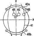
Also have, the control that above-mentioned distortion worsens is shown in Figure 14 A~Figure 14 D and Figure 15 A~Figure 15 D, with on by the roughly the same position of the track correction coil of the track correction means of phosphor screen one side, auxiliary deflection coil 40a, the 40b that constitutes auxiliary deflection means 39 is set, also can be provided with to these deflecting coils 40a, 40b passes to and horizontal yoke current changes auxiliary deflection means roughly the same, that synchronously modulate with vertical deflection.
Wherein, the auxiliary deflection means 39 shown in Figure 14 A~Figure 14 D have the pincushion of magnetic field 41 for horizontal deflection is increased that auxiliary deflection coil 40a, 40b are produced, and become the electric current deformed configurations of passing through greatly along with vertical deflection.Utilize this structure, poor with diagonal angle axle head and horizontal axle head modulated current revised the pincushion distortion of holding about shown in Figure 11, the pincushion distortion of the upper and lower side that the tilt correction of the pincushion field magnetic line of force of usefulness diagonal angle axle head is shown in Figure 11.
Again, the auxiliary deflection means 39 shown in Figure 15 A~Figure 15 D have magnetic field 41 that auxiliary deflection coil 40a, 40b produce for hindering the pincushion of horizontal deflection, become the big structure of passing through greatly of electrorheological along with vertical deflection.Utilize this structure, poor with the modulated current between diagonal angle axle head and the horizontal axle head revised the pincushion distortion of holding about shown in Figure 11, utilizes the inclination of the magnetic line of force of the barrel field of diagonal angle axle head, revises the pincushion distortion of upper and lower side shown in Figure 11.
Also have, such distortion deterioration also can utilize the method that the auxiliary deflection means are set in the position of the track correction means of tube neck one side to be suppressed.
Again, above-mentioned inhibition to the distortion deterioration is not limited to use the track correction means with the effect of vertical deflection synchronization onwards, also can utilize with the track correction means of horizontal deflection synchronization onwards effect and realize.In this case, the electric current by the auxiliary deflection means adopts the electric current of synchronously modulating with horizontal deflection, and the track supplementary means takes to produce basically in vertical direction that the structure in the auxiliary deflection magnetic field of auxiliary deflection gets final product.
Also have, in the superincumbent explanation, two track correction meanss that use stamping forming shadow mask to realize to be provided with in the color cathode-ray tube apparatus of smooth picture are illustrated, and the invention is not restricted to the color cathode-ray tube apparatus of so smooth picture of realization, a track correction means is being set at least, and the focusing or the situation that deterioration takes place that distorts that produce owing to departing from of above-mentioned track correction magnetic field and electron beam orbit are suitable for too.
Describe according to embodiment below.
Figure 16 represents to suppress the structure of the color cathode-ray tube apparatus of focus characteristics deterioration.This color cathode-ray tube apparatus has the panel 43 that is roughly rectangle, be connected in the funnelform glass awl 44 of this panel 43 and be connected in the vacuum casting that the cylindric neck 45 of the minor diameter of this glass awl 44 constitutes.Boring the minor diameter that 44 1 sides play glass awl 44 by glass and partly deflecting coil 47 be installed 46 the outside from this neck 45.At the inner surface of panel 43, be provided with have turn blue, the phosphor screen 13 of the three fluorescence layer of the point-like of green, ruddiness.Keep at a distance with this phosphor screen 13 and disposing on its face in opposite directions the shadow mask 2 (look sorts and uses shadow mask) that in accordance with regulations arrangement pitches forms many electron beam through-holes 48 in opposite directions again.In neck 45, set the central beam 40G and an opposite side bundle 4B, the 4R that launch by same horizontal plane again and become 3 beam electrons bundle 4B of an example configuration, the electron gun arrangements 50 of 4G, 4R.Form the level and the level of frame deflector coil generation and electron beam 4B, 4G, the 4R deflection that vertical deflection magnetic field is launched this electron gun 50 that utilize inclined to one side coil 47 again, carry out level and vertical scanning, the structure of color display by 2 pairs of phosphor screens of shadow mask 13.
Particularly in this color cathode-ray tube apparatus, it is smooth that panel 43 is made display part 51 outer surfaces, and inner surface has the curved surface of some curvature.Relative with this panel 43, the face relative with phosphor screen 13 of shadow mask 2 made the big curved surface of inner surface of the display part 51 of ratio of curvature panel 43.For example, for the diagonal angle effective diameter of phosphor screen 13 about 460 millimeters, the diagonal angle axle head is with respect to the about 10 millimeters panel of the drop of center on tube axial direction of the inner surface of display part 51, shadow mask 2 diagonal angle axle heads are about 16 millimeters with respect to the drop of center on tube axial direction of in opposite directions face, form the big curved surface of interior surface curvature of the display part 51 of ratio panels 43.And the situation of screen characteristics deterioration is taking place because the face curvature in opposite directions of display part 51 inner surfaces of this panel 43 and shadow mask 2 is different in order to prevent, at deflecting coil 47 two track correction meanss are set.
Above-mentioned track correction means as shown in figure 17, no comatic aberration coil 20a by tube neck one side that is arranged at deflecting coil 47, two " コ " font magnetic core 21a of 20b, two groups of track correction coil 22a as the track correction means 14 of tube neck one side of 2 reel respectively on the 21b, 22b and 53a, 53b, and the conduct of supporting the coil rack (not shown go out) of frame deflector coil to go up to reel is by four track correction coil 24a of the track correction means 15 of phosphor screen one side, 24b, 24c, 24d, and to these track correction coils 22a, 22b, 53a, 53b, 24a, 24b, 24c, 24d provides the current supply circuit of electric current to constitute.
As shown in figure 18, the structure of this current supply circuit is, diode 54a, 54b, 54c, 54d are connected in frame deflector coil 23a, 23b by no coma aberration coil 20a, 20b, provide by the parabolic electric current 55 that is roughly shown in Figure 19 A of diode 54a, 54b, 54c, 54d rectification to track correction coil 22a, 22b, 24a, 24b, 24c, 24d, or just to fluoroscopic upside and downside deflection the time, provide electric current 56a, the 56b shown in Figure 19 B and Figure 19 C by diode 54c, 54d to track correction coil 53a, 53b more respectively.Also have, 57a shown in Figure 180,57b are the buffer resistances that makes the high-frequency current bypass that puts on frame deflector coil 23a, 23b.
The track correction means 14 of neck one side utilizes supplies with aforesaid electric current 55,56a, 56b, one opposite side bundle is worked on the direction that excessively focuses on, 15 of track correction meanss by phosphor screen one side work on the direction that focuses on deficiency, and best q value is enlarged 5 millimeter.
And track correction coil 53a, the 53b of the track correction means 14 of tube neck one side are shown in Figure 20 A, have only during to the deflection of phosphor screen upside the track correction coil 53b of downside to produce magnetic field 58 at 3 beam electrons bundle 4B, 4G, 4R, during to the deflection of phosphor screen downside, have only the track correction coil 53a of upside to produce magnetic field 58 at 3 beam electrons bundle 4B, 4G, 4R.Therefore, the summation in the magnetic field of track correction coil 22a, 22b, 53a, 53b generation is identical with the magnetic field 31 shown in Figure 10 A and Figure 10 B.Therefore, utilize said structure can suppress the deterioration of focus characteristics.
Below the color cathode-ray tube apparatus that can suppress distortion performance is illustrated.
The structure of this color cathode-ray tube apparatus color cathode ray tube with shown in Figure 16 basically is identical, venerates the auxiliary deflection means 39 that increase shown in the accompanying drawing 21A thereon.
These auxiliary deflection means 39 provide the current supply circuit of electric current to constitute by two auxiliary deflection coil 40a, 40b of the coil rack that is wound in horizontal deflection coil (not shown go out) and to these two auxiliary deflection coil 40a, 40b shown in Figure 21 B.
This current supply circuit is shown in Figure 21 B, have inductance coil 61a, the 61b of coiling on saturable core 60 and the inductance element 63 that saturated control coil 62 is formed, this inductance coil 61a, 61b and auxiliary deflection coil 40a, 40b are connected in parallel on horizontal deflection coil 64a, the 64b, form structure from vertical yoke current to saturated control coil 62 that supply with.
The load of inductance coil 61a, 61b in the time of can reducing vertical deflection with this reduces the horizontal yoke current that flows to auxiliary deflection coil 40a, 40b, suppresses the distortion performance deterioration shown in Figure 14 A~Figure 14 D.
Below the color cathode-ray tube apparatus that utilizes the means different with embodiment 1 to control the deterioration of focus characteristics is illustrated.
The track correction means of neck one side is taked the structure shown in Figure 22 A in this color cathode-ray tube apparatus, two track correction meanss, and to the auxiliary deflection means 39 shown in its appended drawings 22A and Figure 22 B.
This auxiliary deflection means 39 are shown in Figure 22 A, by being wound in rod core 66a, 66b, be disposed at and two auxiliary deflection coil 67a, 67b not having 3 beam electrons bundle orientation both sides on coma aberration coil 20a, the same tubular axis of 20b and the current supply circuit formation that electric current is provided to these two ancillary coil 67a, 67b.
This current supply circuit takes to insert the structure of auxiliary deflection coil 67a, 67b between no coma aberration coil 22a, the 22b of current supply circuit shown in Figure 180 and diode 54a, 54b shown in Figure 22 B.
Take such structure, auxiliary deflection coil 67a, 67b pass to vertical yoke current, form magnetic pole in 3 electron beam orientation both sides with this, produce 2 pole fields 68 that hinder vertical deflection.Therefore, suitably adjust the intensity in the magnetic field 68 of this auxiliary deflection coil 67a, 67b generation, the 3 beam electrons bundle 4B of track correction means place, 4G, the 4R that can revise tube neck one side depart from vertical direction, suppress the deterioration of focus characteristics.
Adopt aforesaid structure, even use stamping forming shadow mask, the track correction means with high-intensity magnetic field distribution displacement of realizing the inferior uses of situation such as smooth picture is set, also can provide the color cathode-ray tube apparatus of deterioration in characteristics such as not causing focusing or distortion.
Claims (4)
1. color cathode ray tube is characterized in that possessing:
By the panel that is roughly rectangle, be connected with this panel, have the funnelform glass awl of smaller diameter end and the vacuum casting of the neck formation that is connected with the smaller diameter end of this glass awl,
Be arranged at described panel inner surface the phosphor screen with fluorescence coating,
Form on the opposite face of keeping at a distance with this phosphor screen many electron beam through-holes shadow mask,
Be arranged in the above-mentioned neck, have emission comprise the negative electrode of 3 beam electrons bundles of the Cheng Yilie configuration by a conplane central beam and an opposite side bundle and a plurality of electrodes electron gun arrangements,
Be installed on from above-mentioned neck bore the outside that a side plays the minor diameter of above-mentioned glass awl by glass, make above-mentioned 3 beam electrons bundles to as the deflecting coil of the 1st direction of the orientation of this 3 beam electrons bundle and the 2nd direction deflection vertical with the 1st direction and
Be included in a plurality of track correction coils of disposing between the negative electrode of above-mentioned electron gun arrangements and the above-mentioned phosphor screen and the track correction means of revising with the track to described limit bundle of the current supply circuit of the synchronous electric current of the deflection of above-mentioned the 1st direction and/or the 2nd direction is provided to these track correction coils, at least one of this track correction means has the effect that excessively focuses on or focus on deficiency with respect to above-mentioned fluoroscopic center to a described opposite side bundle at described phosphor screen periphery, and betide to exist in the magnetic field of passing through the zone of above-mentioned 3 electron beams above-mentioned 3 beam electrons bundles are not applied the position of active force in above-mentioned the 1st direction and/or the 2nd direction, produce and make the not magnetic field on the face that comprises tubular axis and above-mentioned the 1st direction and/or the 2nd direction, this position.
2. color cathode ray tube is characterized in that possessing:
By the panel that is roughly rectangle, be connected with this panel, have the funnelform glass awl of smaller diameter end and the vacuum casting of the neck formation that is connected with the smaller diameter end of this glass awl,
Be arranged at described panel inner surface the phosphor screen with fluorescence coating,
Form on the opposite face of keeping at a distance with this phosphor screen many electron beam through-holes shadow mask,
Be arranged in the above-mentioned neck, have emission comprise the negative electrode of 3 beam electrons bundles of the Cheng Yilie configuration by a conplane central beam and an opposite side bundle and a plurality of electrodes electron gun arrangements,
Be installed on from above-mentioned neck bore the outside that a side plays the minor diameter of above-mentioned glass awl by glass, make above-mentioned 3 beam electrons bundles to as the deflecting coil of the 1st direction of the orientation of this 3 beam electrons bundle and the 2nd direction deflection vertical with the 1st direction,
Be included in a plurality of track correction coils of disposing between the negative electrode of above-mentioned electron gun arrangements and the above-mentioned phosphor screen and provide current supply circuit with the synchronous electric current of the deflection of above-mentioned the 1st direction and/or the 2nd direction to these track correction coils, to described limit bundle described phosphor screen periphery have with respect to described phosphor screen center excessively focus on or focus on track not enough effect, that revise described limit bundle the track correction means and
Constitute by a plurality of auxiliary deflection coils that between the negative electrode of described electron gun arrangements and described phosphor screen, dispose and current supply circuit from the synchronous electric current of the deflection of described the 1st direction and/or the 2nd direction to these auxiliary deflection coils that supply with, carry out deflection, make described 3 beam electrons bundles in described fluoroscopic periphery at least one auxiliary deflection means to the opposite direction auxiliary deflection of the yawing moment of described deflecting coil.
3. color cathode ray tube is characterized in that possessing:
By the panel that is roughly rectangle, be connected with this panel, have the funnelform glass awl of smaller diameter end and the vacuum casting of the neck formation that is connected with the smaller diameter end of this glass awl,
Be arranged at described panel inner surface the phosphor screen with fluorescence coating,
Form on the opposite face of keeping at a distance with this phosphor screen many electron beam through-holes shadow mask,
Be arranged in the above-mentioned neck, have emission comprise the negative electrode of 3 beam electrons bundles of the Cheng Yilie configuration by a conplane central beam and an opposite side bundle and a plurality of electrodes electron gun arrangements,
Be installed on from above-mentioned neck bore the outside that a side plays the minor diameter of above-mentioned glass awl by glass, make above-mentioned 3 beam electrons bundles to as the deflecting coil of the 1st direction of the orientation of this 3 beam electrons bundle and the 2nd direction deflection vertical with the 1st direction,
Comprise the negative electrode that is disposed at described electron gun and a plurality of track correction coils between the described phosphor screen and be supplied to the current supply circuit of the synchronous electric current of few and the deflection of described the 2nd direction to these track correction coils, to a described opposite side bundle the phosphor screen periphery have with respect to the phosphor screen center excessively focus on or focus on not enough effect at least one track correction means and
Be included in a plurality of auxiliary deflection coils of disposing between the negative electrode of above-mentioned electron gun and the above-mentioned phosphor screen and to these auxiliary deflection coils supply with the deflection of above-mentioned the 1st direction synchronously and with the current supply circuit of the electric current of the deflection synchronous modulation of above-mentioned the 2nd direction, make the auxiliary deflection means of described 3 beam electrons bundles at described fluoroscopic periphery to described the 1st direction auxiliary deflection.
4. color cathode ray tube is characterized in that possessing:
By the panel that is roughly rectangle, be connected with this panel, have the funnelform glass awl of smaller diameter end and the vacuum casting of the neck formation that is connected with the smaller diameter end of this glass awl,
Be arranged at described panel inner surface the phosphor screen with fluorescence coating,
With this phosphor screen keep at a distance the shadow mask that forms many electron beam through-holes on the relative face,
Be arranged in the above-mentioned neck, have emission comprise the negative electrode of 3 beam electrons bundles of the Cheng Yilie configuration by a conplane central beam and an opposite side bundle and a plurality of electrodes electron gun arrangements,
Be installed on from above-mentioned neck bore the outside that a side plays the minor diameter of above-mentioned glass awl by glass, make above-mentioned 3 beam electrons bundles to as the deflecting coil of the 1st direction of the orientation of this 3 beam electrons bundle and the 2nd direction deflection vertical with the 1st direction,
Comprise the negative electrode that is disposed at described electron gun and a plurality of track correction coils between the described phosphor screen and be supplied to the current supply circuit of the synchronous electric current of few and the deflection of described the 1st direction to these track correction coils, to a described opposite side bundle the phosphor screen periphery have with respect to the phosphor screen center excessively focus on or focus on not enough effect at least one track correction means and
Be included in a plurality of auxiliary deflection coils of disposing between the negative electrode of above-mentioned electron gun and the above-mentioned phosphor screen and to these auxiliary deflection coils supply with the deflection of above-mentioned the 2nd direction synchronously and with the current supply circuit of the electric current of the deflection synchronous modulation of above-mentioned the 1st direction, make the auxiliary deflection means of described 3 beam electrons bundles at described fluoroscopic periphery to described the 2nd direction auxiliary deflection.
Applications Claiming Priority (6)
| Application Number | Priority Date | Filing Date | Title |
|---|---|---|---|
| JP37421698 | 1998-12-28 | ||
| JP374216/98 | 1998-12-28 | ||
| JP374216/1998 | 1998-12-28 | ||
| JP37114/99 | 1999-02-16 | ||
| JP11037114A JP2000251761A (en) | 1998-12-28 | 1999-02-16 | Color cathode ray tube device |
| JP37114/1999 | 1999-02-16 |
Publications (2)
| Publication Number | Publication Date |
|---|---|
| CN1299514A true CN1299514A (en) | 2001-06-13 |
| CN1279571C CN1279571C (en) | 2006-10-11 |
Family
ID=26376207
Family Applications (1)
| Application Number | Title | Priority Date | Filing Date |
|---|---|---|---|
| CNB998056588A Expired - Fee Related CN1279571C (en) | 1998-12-28 | 1999-12-28 | Color cathode-ray tube device |
Country Status (7)
| Country | Link |
|---|---|
| US (1) | US6380667B1 (en) |
| EP (1) | EP1063674A4 (en) |
| JP (1) | JP2000251761A (en) |
| KR (1) | KR100432059B1 (en) |
| CN (1) | CN1279571C (en) |
| TW (1) | TW455904B (en) |
| WO (1) | WO2000039833A1 (en) |
Families Citing this family (10)
| Publication number | Priority date | Publication date | Assignee | Title |
|---|---|---|---|---|
| JP2000251761A (en) | 1998-12-28 | 2000-09-14 | Toshiba Corp | Color cathode ray tube device |
| JP2000228156A (en) * | 1999-02-05 | 2000-08-15 | Toshiba Corp | Cathode-ray tube device |
| JP2001035370A (en) * | 1999-07-15 | 2001-02-09 | Mitsubishi Electric Corp | Exposure device for phosphor screen of cathode-ray tube panel |
| JP2001135259A (en) * | 1999-11-02 | 2001-05-18 | Matsushita Electronics Industry Corp | Color cathode-ray tube and apparatus thereof |
| KR100331057B1 (en) * | 1999-12-30 | 2002-04-06 | 구자홍 | DY for Broun tube with auxiliary coil and Method for manufacturing theauxiliary coil |
| US6831400B2 (en) * | 2000-12-27 | 2004-12-14 | Kabushiki Kaisha Toshiba | Color cathode ray tube apparatus having auxiliary magnetic field generator |
| SG114529A1 (en) * | 2001-02-23 | 2005-09-28 | Semiconductor Energy Lab | Method of manufacturing a semiconductor device |
| US6888325B2 (en) * | 2002-07-26 | 2005-05-03 | Samsung Electro-Mechanics Co., Ltd | Method for self correcting inner pin distortion using horizontal deflection coil and deflection yoke thereof |
| US20060043867A1 (en) * | 2004-09-01 | 2006-03-02 | Matsushita Toshiba Picture Display Co., Ltd. | Color picture tube apparatus |
| TWI728999B (en) * | 2016-09-08 | 2021-06-01 | 香港商港大科橋有限公司 | Spatial chirped cavity for temporally stretching/compressing optical pulses |
Family Cites Families (19)
| Publication number | Priority date | Publication date | Assignee | Title |
|---|---|---|---|---|
| US4554488A (en) * | 1981-06-14 | 1985-11-19 | Victor Company Of Japan, Limited | Device for correcting an image on a picture tube having in-line electron guns and a coil assembly for the device |
| JPS60170143A (en) * | 1984-02-14 | 1985-09-03 | Toshiba Corp | Picture tube device |
| JPH0750935B2 (en) * | 1984-05-30 | 1995-05-31 | 株式会社村田製作所 | Deflection-yoke device |
| JPS6218888A (en) * | 1985-07-18 | 1987-01-27 | Victor Co Of Japan Ltd | Convergence correcting device |
| JP2522885Y2 (en) * | 1989-03-28 | 1997-01-16 | 株式会社村田製作所 | Convergence correction device |
| JPH0648736Y2 (en) * | 1989-03-29 | 1994-12-12 | 株式会社村田製作所 | Color deflection yoke |
| JPH0355747A (en) * | 1989-07-24 | 1991-03-11 | Mitsubishi Electric Corp | Deflection yoke |
| US5070280A (en) * | 1989-08-25 | 1991-12-03 | Hitachi, Ltd. | Deflection yoke |
| JPH0392352U (en) * | 1989-12-29 | 1991-09-19 | ||
| US5170097A (en) * | 1991-03-20 | 1992-12-08 | Vincent Montemurro | Intermittent windshield wiper and headlight control |
| JP2964787B2 (en) | 1992-07-31 | 1999-10-18 | トヨタ自動車株式会社 | Bismuth layered compound |
| JP2770710B2 (en) * | 1993-06-30 | 1998-07-02 | 日本ビクター株式会社 | Electromagnetic deflection yoke for color cathode ray tubes |
| US5783901A (en) * | 1994-09-05 | 1998-07-21 | Matsushita Electronics Corporation | Deflection yoke with a core having a higher magnetic reluctance at the top and bottom portions than the sides |
| US6268705B1 (en) * | 1995-01-24 | 2001-07-31 | International Business Machines Corporation | Raster demodulation apparatus and method |
| KR100193576B1 (en) * | 1995-08-28 | 1999-06-15 | 이형도 | Orthogonality Correction Circuit of Deflection Yoke |
| KR970023593A (en) * | 1995-10-26 | 1997-05-30 | 구자홍 | Adjust device of color purity and convergence |
| JP3543900B2 (en) * | 1996-12-27 | 2004-07-21 | 松下電器産業株式会社 | Cathode ray tube device |
| JPH1167123A (en) * | 1997-06-10 | 1999-03-09 | Toshiba Corp | Color picture tube |
| JP2000251761A (en) | 1998-12-28 | 2000-09-14 | Toshiba Corp | Color cathode ray tube device |
-
1999
- 1999-02-16 JP JP11037114A patent/JP2000251761A/en active Pending
- 1999-12-28 KR KR10-2000-7009497A patent/KR100432059B1/en not_active IP Right Cessation
- 1999-12-28 TW TW088123142A patent/TW455904B/en not_active IP Right Cessation
- 1999-12-28 CN CNB998056588A patent/CN1279571C/en not_active Expired - Fee Related
- 1999-12-28 EP EP99961478A patent/EP1063674A4/en not_active Withdrawn
- 1999-12-28 WO PCT/JP1999/007414 patent/WO2000039833A1/en not_active Application Discontinuation
-
2000
- 2000-08-28 US US09/649,836 patent/US6380667B1/en not_active Expired - Fee Related
Also Published As
| Publication number | Publication date |
|---|---|
| KR20010041374A (en) | 2001-05-15 |
| CN1279571C (en) | 2006-10-11 |
| US6380667B1 (en) | 2002-04-30 |
| EP1063674A4 (en) | 2006-11-15 |
| TW455904B (en) | 2001-09-21 |
| EP1063674A1 (en) | 2000-12-27 |
| JP2000251761A (en) | 2000-09-14 |
| KR100432059B1 (en) | 2004-05-20 |
| WO2000039833A1 (en) | 2000-07-06 |
Similar Documents
| Publication | Publication Date | Title |
|---|---|---|
| CN1017204B (en) | Colour display system and tube having electron gun with dual electron modulation | |
| CN1105776A (en) | Cathode ray tube with low dynamic correction voltage | |
| CN1279571C (en) | Color cathode-ray tube device | |
| CN1071936C (en) | Color cathode ray tube | |
| CN1073275C (en) | Color cathode ray tube | |
| US5059858A (en) | Color cathode ray tube apparatus | |
| CN1051870C (en) | Electron gun and cathode-ray tube comprising same | |
| KR100270387B1 (en) | Color cathode ray tube | |
| CN1146007C (en) | Colour cathode-ray tube device | |
| CN1058103C (en) | Color cathode ray tube having improved focus | |
| CN1050442C (en) | Deflection system with controlled beam spot | |
| CN1311506C (en) | Structure of electron gun for cathode ray tube | |
| CN1082715C (en) | Color cathode ray tube with coma reduced | |
| CN1093199A (en) | The electron gun of color cathode ray tube | |
| CN1087487C (en) | Color cathode ray tube | |
| CN1388560A (en) | Colour cathode-ray tube with improved colour purity | |
| CN1320591C (en) | Color cathode ray tube apparatus | |
| CN1130302A (en) | Colour display system by using quadrupole lens | |
| CN1266274A (en) | CRT device | |
| US7471894B2 (en) | Manufacturing method of color cathode ray tube | |
| CN1153249C (en) | Colour Bulao'en tube | |
| CN1133195C (en) | Color cathode-ray tube | |
| CN1233015C (en) | Crt | |
| CN1191603C (en) | Electronic gun and color cathode ray tube therewith | |
| CN1227708C (en) | Coloured cathode ray tube equipment |
Legal Events
| Date | Code | Title | Description |
|---|---|---|---|
| C06 | Publication | ||
| PB01 | Publication | ||
| C10 | Entry into substantive examination | ||
| SE01 | Entry into force of request for substantive examination | ||
| C14 | Grant of patent or utility model | ||
| GR01 | Patent grant | ||
| C19 | Lapse of patent right due to non-payment of the annual fee | ||
| CF01 | Termination of patent right due to non-payment of annual fee |