CN1291763C - Syringe and metod for use thereof - Google Patents
Syringe and metod for use thereof Download PDFInfo
- Publication number
- CN1291763C CN1291763C CNB018218903A CN01821890A CN1291763C CN 1291763 C CN1291763 C CN 1291763C CN B018218903 A CNB018218903 A CN B018218903A CN 01821890 A CN01821890 A CN 01821890A CN 1291763 C CN1291763 C CN 1291763C
- Authority
- CN
- China
- Prior art keywords
- syringe
- main body
- cylinder
- extension
- bar
- Prior art date
- Legal status (The legal status is an assumption and is not a legal conclusion. Google has not performed a legal analysis and makes no representation as to the accuracy of the status listed.)
- Expired - Fee Related
Links
Images

Classifications
-
- A—HUMAN NECESSITIES
- A61—MEDICAL OR VETERINARY SCIENCE; HYGIENE
- A61M—DEVICES FOR INTRODUCING MEDIA INTO, OR ONTO, THE BODY; DEVICES FOR TRANSDUCING BODY MEDIA OR FOR TAKING MEDIA FROM THE BODY; DEVICES FOR PRODUCING OR ENDING SLEEP OR STUPOR
- A61M3/00—Medical syringes, e.g. enemata; Irrigators
- A61M3/02—Enemata; Irrigators
- A61M3/0279—Cannula; Nozzles; Tips; their connection means
-
- A—HUMAN NECESSITIES
- A61—MEDICAL OR VETERINARY SCIENCE; HYGIENE
- A61M—DEVICES FOR INTRODUCING MEDIA INTO, OR ONTO, THE BODY; DEVICES FOR TRANSDUCING BODY MEDIA OR FOR TAKING MEDIA FROM THE BODY; DEVICES FOR PRODUCING OR ENDING SLEEP OR STUPOR
- A61M5/00—Devices for bringing media into the body in a subcutaneous, intra-vascular or intramuscular way; Accessories therefor, e.g. filling or cleaning devices, arm-rests
- A61M5/178—Syringes
-
- A—HUMAN NECESSITIES
- A61—MEDICAL OR VETERINARY SCIENCE; HYGIENE
- A61M—DEVICES FOR INTRODUCING MEDIA INTO, OR ONTO, THE BODY; DEVICES FOR TRANSDUCING BODY MEDIA OR FOR TAKING MEDIA FROM THE BODY; DEVICES FOR PRODUCING OR ENDING SLEEP OR STUPOR
- A61M1/00—Suction or pumping devices for medical purposes; Devices for carrying-off, for treatment of, or for carrying-over, body-liquids; Drainage systems
- A61M1/80—Suction pumps
- A61M1/81—Piston pumps, e.g. syringes
-
- A—HUMAN NECESSITIES
- A61—MEDICAL OR VETERINARY SCIENCE; HYGIENE
- A61M—DEVICES FOR INTRODUCING MEDIA INTO, OR ONTO, THE BODY; DEVICES FOR TRANSDUCING BODY MEDIA OR FOR TAKING MEDIA FROM THE BODY; DEVICES FOR PRODUCING OR ENDING SLEEP OR STUPOR
- A61M3/00—Medical syringes, e.g. enemata; Irrigators
- A61M3/02—Enemata; Irrigators
- A61M3/0233—Enemata; Irrigators characterised by liquid supply means, e.g. from pressurised reservoirs
- A61M3/0254—Enemata; Irrigators characterised by liquid supply means, e.g. from pressurised reservoirs the liquid being pumped
- A61M3/0262—Enemata; Irrigators characterised by liquid supply means, e.g. from pressurised reservoirs the liquid being pumped manually, e.g. by squeezing a bulb
-
- A—HUMAN NECESSITIES
- A61—MEDICAL OR VETERINARY SCIENCE; HYGIENE
- A61M—DEVICES FOR INTRODUCING MEDIA INTO, OR ONTO, THE BODY; DEVICES FOR TRANSDUCING BODY MEDIA OR FOR TAKING MEDIA FROM THE BODY; DEVICES FOR PRODUCING OR ENDING SLEEP OR STUPOR
- A61M5/00—Devices for bringing media into the body in a subcutaneous, intra-vascular or intramuscular way; Accessories therefor, e.g. filling or cleaning devices, arm-rests
- A61M5/178—Syringes
- A61M5/31—Details
- A61M5/3148—Means for causing or aiding aspiration or plunger retraction
-
- A—HUMAN NECESSITIES
- A61—MEDICAL OR VETERINARY SCIENCE; HYGIENE
- A61M—DEVICES FOR INTRODUCING MEDIA INTO, OR ONTO, THE BODY; DEVICES FOR TRANSDUCING BODY MEDIA OR FOR TAKING MEDIA FROM THE BODY; DEVICES FOR PRODUCING OR ENDING SLEEP OR STUPOR
- A61M5/00—Devices for bringing media into the body in a subcutaneous, intra-vascular or intramuscular way; Accessories therefor, e.g. filling or cleaning devices, arm-rests
- A61M5/178—Syringes
- A61M5/31—Details
- A61M5/315—Pistons; Piston-rods; Guiding, blocking or restricting the movement of the rod or piston; Appliances on the rod for facilitating dosing ; Dosing mechanisms
- A61M5/31511—Piston or piston-rod constructions, e.g. connection of piston with piston-rod
Abstract
A syringe and its method of use, comprising two bodies; the first body or cylinder provided with a support surface at its end, and a second body or rod with pusher elements, which is introduced in the prior cylinder. The syringe can be used by means of a single hand and it is possible to perform the two actions of a syringe, sucking and injection, by changing the position of the fingers.
Description
Technical field
The present invention relates to a kind of syringe and using method thereof, this syringe is made by a work implement, except other is used, is mainly used in health field, in order to implement the extraction of medicine injection and blood or body fluid.The present invention can also be used in the laboratory of different purposes, other aspect that needs syringe that liquid is handled in the factory, or is used for veterinary's application.The invention still further relates to a kind of method that can utilize this syringe extraction and drain with a hands.
Background technology
In the prior art, adopt various dissimilar syringes, so that adapt to various needs according to the type of the work of being carried out.According to aspect that is used for and application, have different syringes, but in all spectra, the operation of conventional syringe all is common and consistent.
Because utilizing a syringe to extract a large amount of water and it is assigned to from glass does not need in the less container and stings perforating veins and from an attention and the stability that people's withdraw blood is same, so conventional syringe according to they applied operations, need be operated with either large or small stability.
The major defect of conventional syringe and problem are to use them with two handss simultaneously.
Because the syringe needle that the unpredictable motion on the patient part may cause syringe causes damage to the user of patient or syringe, is dangerous so take two handss simultaneously.
In order to prevent above-mentioned danger, known different syringe or be used for the adapter of conventional syringe, making can be only with a hands use syringe.
United States Patent (USP) 3,819,091 has described a kind of adapter that is used for conventional syringe, and this adapter is made of a handle, and described handle helps only carrying out with a hands extraction operation of syringe.This adapter has only solved in syringe stablizes the problem that extracts with a hands, so but owing to must make syringe and adapter has increased manufacturing cost.Because adapter only is used to extract and be used for this fact of syringe of special diameter, so, then need it is separated and be used for injection or discharge purpose as conventional syringe from adapter in case syringe is filled.
United States Patent (USP) 3,990,446 have described a kind of syringe, and this syringe can only extract with a hands, but the discharge of liquid must be undertaken by two handss.Because need have the fixed surface that supports finger extracting, and this fixed surface is positioned at definite distance, the side support member that is positioned at piston rear end must move along described definite distance, so this syringe is longer than the syringe of transmission.
United States Patent (USP) 5,135,511 have described a kind of adapter that is used for conventional syringe, and it can only be extracted with a hands.Except two members that constitute conventional syringe, this adapter also is made of two parts, therefore makes its assembling complicated.Because number of components is more, so adopt this adapter more fault can in use occur.
United States Patent (USP) 5,582,595 described syringes are different with said syringe or adapter, allow one hand to extract and injection operation.The subject matter of this syringe is that its assembling may in use cause fault.This syringe is made of two major parts: the cylinder of the bar that extends as the rear portion that has matching surface to it and have the piston of two supporting surfaces on its end.Subject matter is, for assembled syringe, piston must be incorporated in the rear portion of cylinder, this means that the surface that is arranged in the cylinder rear end must can be with respect to a pivot of described bar.This makes manufacturing process and product more expensive with assembling.Because pivot surface may be removed in extraction process, so this means that also user must operate dexterousr and carefully.In this syringe, piston type is similar to the piston of conventional syringe, is the unique parts with respect to the cylinder motion, so described bar is maintained fixed owing to being connected on the cylinder.
The disadvantage of the syringe of this pattern is, because required power is applied in than conventional syringe from the farther distance of syringe needle, so in use be difficult to syringe needle is controlled in using.
Syringe as purpose of the present invention, owing to can implement extremely simply to extract and discharge by flexing one's fingers naturally with comfortable, stable and safe power, at any time the motion and the syringe needle of syringe are controlled, so utilize this syringe to solve shortcoming in the aforementioned syringe.In the aforementioned documents, do not have one piece easy like that to following syringe, allow the syringe of manufacturing only to use with a hands, and be provided with two can be easily and the rapid independent subject of assembling.
Summary of the invention
The present invention owing to can implement the extraction of liquid and discharge two kinds of operations with the bending of same pressure effect or finger, so this syringe and the method for utilizing this syringe that liquid is extracted and discharges are provided with a kind of special structure, this structure allows only to use with a hands and can stably operate.If conventional syringe is because only with a hands then can puncture or injure the user or the patient of syringe, so must use two handss when extraction.
In order only to use syringe with a hands, traditional syringe has been carried out different architecture advances, still kept the simplicity of using and making.
This syringe is provided with two main bodys or element, a cylinder that at one end has liquid inlet and/or outlet opening, two sidepiece pods at the opposite end opening, with a center support face that has with respect to the center cavity of cylinder horizontally set, this center support mask has anterior or the 3rd supporting surface in a rear portion or second supporting surface and another.
Second main body is made of a bar and two extensions, and this bar at one end has a piston, and two extensions have link or impeller at the relative other end.On a side of extending to free end (being incorporated into the end in the cylinder), extension or impeller end at the supporting surface (the 4th supporting surface) of two cross-section described extensions or impeller, and on opposite end, extension or impeller all link to each other with another supporting surface (first supporting surface).
According to the diameter of syringe, the thickness of extension or bigger or less.Have at cylinder under the situation of syringe of less diameter, described extension is bigger at the thickness at the place, end that covers described bar, so that make the motion of bar have bigger stability, and allows to make finger to enter wherein metapore broad.In large diameter syringe, the thickness of these extensions is less or basic identical.
The present invention can also provide a kind of syringe, and it has two fins that are connected on the extension end, enters into connector along its groove that moves in order to prevent exterior object.
In order to use this syringe, need be according to the following described finger of placing a hands in special mode.As under the situation of conventional syringe, this syringe has two end positions, and one is used to extract liquid and another is used for drain.In first position, preparation extract and piston near or contact with the hole of cylinder, finger, promptly any finger except that thumb is placed on the 4th supporting surface, and thumb is placed on second supporting surface in the mode in the boundary window between second supporting surface and first supporting surface.In case place finger, then only need exert pressure or flexure operation with finger, therefore, produces two with the piston parallel reverse pressure of moving, cause the relative motion of two main bodys, thus extraction liquid.
In order to discharge the syringe cylinder liquid that after extracting, is positioned on its second position, must change the position of finger, but not need to decontrol syringe, do not need with another hands oneself auxiliary yet., thumb is placed on first supporting surface for this reason, and two other fingers are placed on the 3rd supporting surface.Be positioned under these locational conditions at finger, carry out another pressurization or flexure operation with finger, thereby produce two opposite power that are parallel to the piston direction of motion, make two main body relative motioies, thereby discharge or injecting fluid.
Adopt said structure, need not rotate hands, wrist or syringe in order to use syringe.Three fingers with a hands just are enough to carry out continuously conversion, extract and the operation of drain with safety, stable manner.
Because this syringe is simple to operate, thus can learn at an easy rate, without any need for training.Utilize this syringe, can realize two functions rapidly, safely, prevent user owing to operation injures he or she oneself, and suppress uncontrolled motion.
Because the bar in the direction of utilizing the power that thumb applies and the cylinder and the axis of movement of piston are consistent, so the motion that control is extracted and discharged is always stable, safely and be controlled fully.
Adopt this design, do not need to decontrol syringe, it is auxiliary also not need to carry out the oneself with the another hands, when extracting the position and be transformed into drain position or under opposite situation, need not rotate hands or syringe for the position of two fingers of conversion.
Extract and discharge process in safety, stability and be controlled fully, also be owing to the pressurization of the position that only needs to change finger, finger or flecition are this identical true realization in two actions, therefore only need to change the position of finger, help easily to operate and learn to use this syringe.
Only use with stable and controlled way, can prevent that user is punctured and otch because of carelessness when under the help of syringe needle, extracting liquid, therefore can avoid infection with a hands.
Extracting blood or inserting the liquid under the situation of blood vessel, this syringe has following advantage,, only needs to use a hands that is, and the finger of another hands can be used to keep the invariant position of blood vessel.
The syringe that goes for having one or more purposes as the structure of this syringe of the object of the invention, and can be used to implement medicine injection, blood draw, biological tissue puncture etc.
Description of drawings
In order to help to understand this syringe and utilize this syringe to carry out the method for Liquid extracting and discharge, present patent application provides seven width of cloth figure, its objective is and help understanding better the basis that invention is discussed, and understand the explanation of preferred embodiment better, it is exemplary that accompanying drawing is considered to, but not determinate.
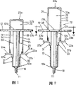
Fig. 1 represents as the front view purpose of present patent application, that prepare the syringe of extraction liquid.
Fig. 2 represents to prepare to discharge the syringe front view of the liquid that extracts in advance.
Fig. 3 represents the upper plane figure of the sub-body or first main body.
Fig. 4 represents the decomposition diagram of two parts of syringe.
Fig. 5 represents the perspective view of syringe.
Fig. 6 is illustrated in the front view of syringe on primary importance that is using in the process that extracts liquid, wherein, can observe the position of the finger of syringe user.
Fig. 7 is illustrated in the front view of syringe on the second position that is using in the process of drain, wherein, can observe the position of the finger of syringe user.
The specific embodiment
Syringe of the present invention and using method are the novel settings to the different elements of conventional syringe.It comprises new element, these new elements allow to carry out and extract out or extraction and discharge the basic operation of these two syringes by only applying same finger pressurization or bending force with a hands of user, while keeps stability in the process of use syringe, and the more easy and safety of therefore feasible use.
This syringe has two main bodys or basic structure independently, and they preferably are being molded as a single-piece, and each has specific composition.First main body 10 is columnar, and has a front end 10a and one second opening or oral area 10b, and the inlet and/or the outlet opening 11 that are used for liquid are arranged on described front end 10a.At the front end place of syringe 10a, except inlet and/or outlet opening 11, also have and be used for hypodermic needle is connected to mechanism 16 on the described front end 10a.
Second main body 20 is made of one first parts or bar 21, and these first parts or bar 21 are inserted in first main body or the cylinder 10 by the oral area 10b of described main body 10.Bar 21 has piston 21a in its end near the hole of syringe 11, and has a brake component 21b in opposite end.Second main body 20 can be moved between the two positions, and described two positions are that the primary importance (Fig. 6) of the front end 10a of the close cylinder 10 of piston 21a and piston 21a are away from the second position (Fig. 7) of the front end 10a of cylinder 10.Like this, in order to extract liquid by hole 11, second main body 20 is moved to the second position from primary importance, and in order to discharge the liquid that is contained in the syringe by hole 11, and second main body 20 is moved to primary importance from the second position.
This syringe has basic supporting surface between four two main bodys 10,20 that are distributed in it, that be used to operate.
Second main body 20 is divided into two parts, and one is the bar 21 on that the front had been said, as to be positioned at described main body 20 end, and another is second portion or impeller 22.Described impeller 22 has two extensions 24,25, these two extensions 24,25 are connected by the first supporting surface 23a at their 22b place, rear portion, exert pressure at the first supporting surface 23a upper edge first axle direction C, so that described second main body 20 is moved to described primary importance from the described second position.
The impeller 22 of second main body 20 has two the 4th stayed surface 27a, 27b that are made of two side flange 24a, 25a in its front end 22a, wherein each side flange lays respectively on the free end of one of extension 24,25, can exert pressure thereon along second axis direction opposite, so that second main body 20 is moved to the second position from primary importance with the first axle direction.
According to the diameter of syringe, the thickness of extension 24,25 is either large or small.Cylinder 10 in syringe has under the situation of minor diameter, and described extension 24,25 is bigger at the thickness at the front end 22a place that covers described bar, so that make the motion stabilization of main body 21, and can make and hole 26 is widened so that point and enter.In the major diameter syringe, these extensions 24,25 have than the little or similar thickness of described extension at front end 22a place.
Can also make syringe be provided with two tongue- like parts 30,31 that link to each other with the end of extension 24,25, enter connector 28,29 along in its groove that moves 13,14 so that prevent exterior object.
For can be along applying power with the piston identical direction of moving in extraction process, syringe has a window or hole 26 in second main body 20.Described hole 26 is enough big, and the thumb with user when being in primary importance with convenient second main body 20 is incorporated into wherein.Before extracting liquid, described hole 26 in this position is limited to the oral area 10b place of cylinder 10 by sidepiece extension 24,25, described sidepiece extension 24,25 is connected on the bar 21 of second main body 20 by connector 28,29, and is connected on the rear end 22b of second main body 20 by the first supporting surface 23a in turn.In extraction process, the size of described hole or window 26 increases, up to it till arriving maximum on the second position.Then, utilize one in the bar 21 brake component 21b, utilize extension 24,25 and utilize the first supporting surface 23a on the described extension 24,25 of rear end 22b place connection to limit described hole 26.
In order to allow second main body 20 with respect to 10 motions of first main body, the latter comprises at least two pods 13,14 at its oral area 10b place, and described pod 13,14 extends to the front end 10a of cylinder from described oral area 10b.Connector 28,29 is arranged in these pods 13,14, and described connector 28,29 links to each other with the extension 24,25 of impeller 22 and the brake component 21b of bar 21.When the piston 21a of bar 21 be arranged in primary importance, when promptly contacting with hole 11, groove 13,14 extends to connector 28,29 position occupied from the oral area 10b of cylinder 10.
When second main body 20 is in primary importance, prepare to extract or pumping liquid, the brake component 21b of bar 21 is positioned at apart from the position of the oral area 10b certain distance of cylinder 10, the degree that this distance is moved between the described primary importance and the described second position corresponding to second main body 20.In case finish and extract and before drain, when promptly second main body 20 is positioned on the second position, be positioned on the level identical with the oral area 10b of cylinder 10 at the brake component 21b of bar 21.
Above-mentioned support component 12 as the center support face has an open pore 15, and the shape of this open pore 15 allows bar 21, the connector 28,29 of the first supporting surface 27a, 27b and the part of extension 24,25 to enter along axis direction.Described open pore 15 has and is used for extension 24,25 is kept localized side supports edge 15a.
In order to change to primary importance, that is, before discharge is contained in liquid in the syringe, finger need be placed on the 3rd supporting surface 23b from the second position.Therefore the distance between this supporting surface 23b and the impeller 22 front end 22a is that user can be placed on a finger distance on each side of syringe.
Syringe has a special purposes when extracting blood, so when needs thrust blood vessel, we can use syringe to extract or suction blood and discharge or introducing medicine with the another hands with a position that finger keeps blood vessel of a hands simultaneously.
In order to use syringe pump liquid, the hole 11 of first main body 10 need be placed in the liquid, contact with liquid, and make bar 21 be arranged in primary importance.In case after doing like this, the finger of this hands must be positioned on the different surfaces of syringe, so that thumb placed the hole 26 that is limited by the first supporting surface 23a at the 22b place, rear end of the brake component 21b of bar 21, extension 24,25 and impeller 22; Simultaneously, two of the same hand fingers must be placed on the 4th supporting surface 27a, the 27b.In order to extract liquid, must utilize the thumb on the second supporting surface 12a to exert pressure along first axle direction C with syringe; And must exert pressure along the second axis direction D opposite simultaneously, so that second main body 22 is moved to the second position from primary importance with two fingers of the same hand on the 4th supporting surface 27a, 27b with first axle direction C.
In this action because when extracting release, brake component 21b with enter hole 26 and be positioned at thumb contact on the second supporting surface 12a, so the brake component 21b of bar 21 helps to make the loading to syringe to be not more than its maximum capacity.
Except preventing from cylinder 10, to extract out this method of bar 21, in the inner surface of cylinder, be provided with the ring 17 of a projection, this ring 17 its objective is to make described bar 21 be difficult to extract out from cylinder 10 near the oral area 10b of cylinder 10.
Discharge for the liquid that will introduce syringe in advance, thumb need be placed on the first supporting surface 23a, and two fingers of the same hand are placed on the 3rd supporting surface 23b.In case be placed on finger on the syringe and hole 11 be arranged on container or the test tube so that receive the material that syringe holds, then exert pressure along the first axle direction with thumb, and exert pressure along second axis direction opposite with described finger, so that make second main body 22 move to primary importance from the second position with the first axle direction.
In order only to carry out aforementioned movement in stable, safe and simple mode with a hands, syringe must have special and specific structure, this structure allows to exert pressure on syringe with finger, so that no matter be on same direction or another direction, all to carry out in the direction of the applied force mode identical with the piston travel direction according to extracting or discharge motion.
In the scope of its substitutive characteristics, the present invention can be only to realize with other different embodiment of the embodiment of way of example explanation in detail with at this.Therefore, so long as within the scope of the claims, can with optimal mode and material and the most easily adnexa, realize the present invention according to Any shape and size, and composed component can replace with the alternate manner of technical equivalence.
Claims (18)
1. syringe comprises:
First main body (10) with drum, described first main body have front end (10a) and second opening or oral area (10b), and liquid inlet and/or outlet opening (11) are arranged in described front end,
By second main body (10) that first parts or bar (21) constitute, second body front end has piston (21a), and the described bar (21) of described second main body (20) is inserted in the cylinder (10) by the oral area (10b) of described cylinder (10); Described second main body (20) can be moved between the primary importance and the second position, in primary importance, the piston (21a) of bar (21) is on the position near the front end (10a) of cylinder (10), in the second position, the described piston (21a) of bar (21) is on the position away from the front end (10a) of cylinder (10), thereby second main body (20) is moved so that by hole (11) pumping liquid to the described second position from described primary importance, and second main body (20) is moved so that by hole (11) drain to described primary importance from the described second position;
Described second main body (20) has second portion or impeller (22), and it has front end (22a) and rear end (22b); The described rear end (22b) of impeller (22) constitutes first stayed surface (23a), can exert pressure on this first stayed surface (23a) along the first axle direction, so that make second main body (20) move to primary importance from the second position;
This cylinder (10) comprises with respect to the cylinder transverse projections in its brake component (10b) and forms the center support face (12) of the integral part of this cylinder (10); Described intermediate support surfaces (12) constitutes second supporting surface (12a) on its rear surface, and on its front surface, constitute the 3rd supporting surface (12b), can exert pressure to described supporting surface along second axis direction opposite, so that second main body (20) is moved to primary importance from the second position with the first axle direction;
It is characterized in that,
The impeller (22) of second main body (20) comprises two extensions (24,25), described extension is connected on the bar (21) of second main body (20) by connector (28,29), and be connected to the rear end (22b) of impeller by first supporting surface (23a), thereby form the hole (26) that brake component (21b), center support face (12), extension (24,25) and first supporting surface (23a) by bar (21) are limited;
Wherein,
The impeller (22) of second main body (20) locates to form the 4th supporting surface (27a, 27b) at its front end (22a), can on described supporting surface, exert pressure along second axis direction opposite, so that second main body (20) is moved to the second position from primary importance with the first axle direction;
Wherein,
Cylinder (10) locates to comprise at least two pods (13,14) at its oral area (10b), described two pods (13,14) extend from the front end (10a) of described oral area (10b) to cylinder (10), so that brake component (21b) position occupied of bar is placed primary importance;
And wherein,
The extension (24,25) of the impeller (22) of second main body (20) is connected to by connector (28,29) on the brake component (21b) of bar (21) of described second main body (20), and described connector (13,14) is installed in the described pod (13,14).
2. syringe as claimed in claim 1 is characterized in that, when second main body (20) when being in primary importance, hole (26) have enough big size so that allow the thumb of user to enter into described hole (26); This hole (26) is limited in this position with first supporting surface of locating at rear end (22b) to link to each other with described extension (24,25) (23a) by the oral area of first main body (10) (10b), center support face (12), extension side member (24,25).
3. the described syringe of any one claim as described above, it is characterized in that, when second main body (20) is in the primary importance, the brake component (21b) of bar (21) is positioned at and the oral area (10b) of cylinder (10) position at a distance of certain distance, and described distance is corresponding with the range of movement of second main body (20) between the primary importance and the second position.
4. syringe as claimed in claim 1 is characterized in that, when second main body (20) was in the second position, the brake component (21b) of the bar (21) of second main body (20) was positioned on the level identical with the oral area (10b) of cylinder (10).
5. syringe as claimed in claim 1, it is characterized in that, support component (12) has open pore (15), open pore (15) forms in the following manner, that is, it allows the part of bar (21), connector (28,29), the 4th stayed surface (27a, 27b) and the extension (24,25) of second main body (20) to enter along axis direction.
6. syringe as claimed in claim 5 is characterized in that, the open pore (15) of support component (12) has side bearing edge (15a), and this side bearing edge (15a) is used for extension (24,25) is kept the location.
7. syringe as claimed in claim 1 is characterized in that, when bar (21) be positioned at hole (11) position contacting on the time, groove (13,14) extends to connecting rod (28,29) position occupied from the oral area (10b) of cylinder (10).
8. syringe as claimed in claim 7, it is characterized in that, have two fins (30,31) on the end (22a) that is connected to extension (24,25), enter in the groove (13,14) in order to prevent any external object, and prevent that connecting rod (28,29) from moving along described groove.
9. syringe as claimed in claim 1, it is characterized in that, when second main body (20) is on its second position, distance between the front end (22a) of the impeller (22) of the 3rd supporting surface (23b) and second main body (20) makes user between the described front end (22a) of the impeller (22) of second main body (20) and described the 3rd supporting surface (23b) finger to be placed on each side of syringe.
10. syringe as claimed in claim 1 is characterized in that, the 4th supporting surface (27a, 27b) is made of two side flanges (24a, 25a), and each of described side flange (24a, 25a) is positioned on the free end of one of extension (24,25).
11. syringe as claimed in claim 1 is characterized in that, only needs a hands to use.
12. syringe as claimed in claim 1 is characterized in that, locates at the front end (10a) of cylinder (10), is provided with to be used for hypodermic needle is connected to mechanism (16) on the described front end (10a) of described cylinder (10).
13. syringe as claimed in claim 1 is characterized in that, first main body (10) is for being molded as the main body of a single-piece.
14. syringe as claimed in claim 1 is characterized in that, second main body (20) is for being molded as the main body of a single-piece.
15. syringe as claimed in claim 1 is characterized in that, according to the diameter of the cylinder (10) of syringe, extension (24,25) is at the thickness at impeller (22a) front end place or bigger or less.
16. syringe as claimed in claim 15, it is characterized in that, for syringe with little drum diameter (10), extension (24,25) is bigger than the thickness of described extension (24,25) at the thickness at impeller (22a) front end place, so that thumb can enter into the hole (26) that is limited width by the interval between the extension (24,25).
17. syringe as claimed in claim 15, it is characterized in that, for syringe with large cylinder diameter (10), extension (24,25) is littler or similar than the thickness of extension (24,25) at the thickness at impeller (22a) front end place, so that thumb can enter into the hole (26) that is limited width by the interval between the extension (24,25).
18. syringe as claimed in claim 1, it is characterized in that, at the ring (17) that syringe described in the inner surface of cylinder (10) has at least one projection, the ring of this projection (17) is extracted out from cylinder (10) in order to anti-stopping bar (21) near the oral area (10b) of cylinder (10).
Applications Claiming Priority (2)
| Application Number | Priority Date | Filing Date | Title |
|---|---|---|---|
| ES200100060A ES2187333B1 (en) | 2001-01-10 | 2001-01-10 | SYRINGE AND METHOD OF USE. |
| ESP200100060 | 2001-01-10 |
Publications (2)
| Publication Number | Publication Date |
|---|---|
| CN1496274A CN1496274A (en) | 2004-05-12 |
| CN1291763C true CN1291763C (en) | 2006-12-27 |
Family
ID=8496370
Family Applications (1)
| Application Number | Title | Priority Date | Filing Date |
|---|---|---|---|
| CNB018218903A Expired - Fee Related CN1291763C (en) | 2001-01-10 | 2001-05-10 | Syringe and metod for use thereof |
Country Status (19)
| Country | Link |
|---|---|
| US (1) | US20040073172A1 (en) |
| EP (1) | EP1360969B1 (en) |
| JP (1) | JP4233325B2 (en) |
| KR (1) | KR20030079943A (en) |
| CN (1) | CN1291763C (en) |
| AT (1) | ATE345830T1 (en) |
| AU (1) | AU2001256373B2 (en) |
| BR (1) | BR0116800A (en) |
| CA (1) | CA2444538C (en) |
| CZ (1) | CZ20032091A3 (en) |
| DE (1) | DE60124773T2 (en) |
| ES (2) | ES2187333B1 (en) |
| IL (1) | IL156881A0 (en) |
| MA (1) | MA26268A1 (en) |
| MX (1) | MXPA03006170A (en) |
| PL (1) | PL365341A1 (en) |
| RU (1) | RU2266756C2 (en) |
| WO (1) | WO2002055141A1 (en) |
| ZA (1) | ZA200306067B (en) |
Cited By (1)
| Publication number | Priority date | Publication date | Assignee | Title |
|---|---|---|---|---|
| CN108982642A (en) * | 2018-05-24 | 2018-12-11 | 清华大学深圳研究生院 | A kind of method and device of jamming pattern signal when removing mass spectrograph sample introduction |
Families Citing this family (20)
| Publication number | Priority date | Publication date | Assignee | Title |
|---|---|---|---|---|
| ES1060690Y (en) | 2005-07-05 | 2006-02-01 | Prieto Carracedo Jose Luis | INJECTOR DEVICE FOR SYRINGES |
| GB0608046D0 (en) * | 2006-04-25 | 2006-05-31 | Star Syringe Ltd | Syringe |
| SE530930C2 (en) * | 2006-07-07 | 2008-10-21 | Insulution Svenska Ab | Syringe and syringe assembly |
| JP2010528789A (en) * | 2007-06-13 | 2010-08-26 | デュオジェクト・メディカル・システムズ・インコーポレイテッド | Device for transferring liquid from cartridge to container |
| GR1007306B (en) * | 2010-01-11 | 2011-06-08 | Αναστασιος Ιωαννη Παπαχριστοδουλου | Blood syringe |
| JP5695484B2 (en) * | 2011-04-28 | 2015-04-08 | 株式会社吉野工業所 | Syringe |
| JP5749084B2 (en) * | 2011-05-31 | 2015-07-15 | 株式会社吉野工業所 | Single-use syringe |
| CN102813979A (en) * | 2011-09-30 | 2012-12-12 | 南通新诚电子有限公司 | Novel medical intramuscular injection device |
| US9067023B2 (en) | 2011-11-21 | 2015-06-30 | University Of Louisville Research Foundation, Inc. | Ergonomic syringe and adaptor |
| CN102759462A (en) * | 2012-06-21 | 2012-10-31 | 李双喜 | Bidirectional injector |
| RU2530667C2 (en) * | 2012-10-11 | 2014-10-10 | Олег Владимирович Печурин | Medical syringe |
| GB201321078D0 (en) * | 2013-11-29 | 2014-01-15 | Smiths Medical Int Ltd | Syringe assemblies |
| IL264858B2 (en) * | 2016-08-17 | 2023-10-01 | Nisha Sawhney | Injection monitoring device and system |
| SA117390001B1 (en) | 2017-09-21 | 2018-09-17 | عبدالرحمن عبدالله السحيباني عبدالعزيز | Single Plunger Withdrawing and injecting Syringe |
| US11589850B2 (en) | 2017-10-05 | 2023-02-28 | Vladislav Alexandrovich ODINTSOV | Aspiration syringe |
| RU2677356C1 (en) * | 2017-10-05 | 2019-01-16 | Владислав Александрович Одинцов | Syringe for aspiration |
| RU177324U1 (en) * | 2017-10-05 | 2018-02-15 | Владислав Александрович Одинцов | ASPIRATION SYRINGE |
| SA118390710B1 (en) | 2018-07-11 | 2019-12-02 | عبدالرحمن عبدالله السحيباني عبدالعزيز | Syringe for One-Handed Injection and Aspiration |
| SA119400915B1 (en) * | 2019-08-06 | 2021-05-30 | عبدالرحمن عبدالله السحيباني عبدالعزيز | Syringe Adapter for Single-handed Operation During Aspiration Operation |
| US11541182B2 (en) | 2020-01-14 | 2023-01-03 | Alsahab Medical Company | Integrated syringe and guidewire system |
Family Cites Families (12)
| Publication number | Priority date | Publication date | Assignee | Title |
|---|---|---|---|---|
| US2842128A (en) * | 1955-05-19 | 1958-07-08 | Becton Dickinson Co | Thumb ring for hypodermic syringe |
| US3814091A (en) * | 1972-01-17 | 1974-06-04 | M Henkin | Anesthesia rebreathing apparatus |
| US3819091A (en) * | 1973-04-16 | 1974-06-25 | Castenfors H | Syringe appliance |
| US3990446A (en) * | 1975-02-18 | 1976-11-09 | Jewel Dean Randolph Taylor | Hypodermic syringe for stabilized aspiration by one hand |
| US4484905A (en) * | 1980-03-31 | 1984-11-27 | Harper & Tunstall Limited | Zig-zag folding machines |
| US4324241A (en) * | 1980-09-09 | 1982-04-13 | Alfred D. Lobo | Hypodermic syringe operable with double-looped ring |
| CH661444A5 (en) * | 1984-12-07 | 1987-07-31 | Jean Denis Schweblin Dr | Syringe |
| DE3806404C2 (en) * | 1988-02-29 | 1994-06-09 | Raymond A Gmbh & Co Kg | Detachable connector for semi-rigid pipes |
| FR2636537A1 (en) * | 1988-09-16 | 1990-03-23 | Garde Claude | Suction and withdrawal syringe |
| US4919657A (en) * | 1988-11-14 | 1990-04-24 | Habley Medical Technology Corporation | Dental syringe having a medication filled carpule and a retractable needle cannula |
| US5582595A (en) * | 1995-09-28 | 1996-12-10 | Habley Medical Technology Corporation | Aspirating syringe having a plunger guide for a reciprocating plunger assembly |
| US5569210A (en) * | 1995-11-06 | 1996-10-29 | Moen; Michael | Multiple draw syringe |
-
2001
- 2001-01-10 ES ES200100060A patent/ES2187333B1/en not_active Expired - Fee Related
- 2001-05-10 KR KR10-2003-7009210A patent/KR20030079943A/en active IP Right Grant
- 2001-05-10 JP JP2002555872A patent/JP4233325B2/en not_active Expired - Fee Related
- 2001-05-10 IL IL15688101A patent/IL156881A0/en unknown
- 2001-05-10 PL PL01365341A patent/PL365341A1/en unknown
- 2001-05-10 WO PCT/ES2001/000182 patent/WO2002055141A1/en active Search and Examination
- 2001-05-10 US US10/250,825 patent/US20040073172A1/en not_active Abandoned
- 2001-05-10 CA CA002444538A patent/CA2444538C/en not_active Expired - Fee Related
- 2001-05-10 CN CNB018218903A patent/CN1291763C/en not_active Expired - Fee Related
- 2001-05-10 MX MXPA03006170A patent/MXPA03006170A/en not_active Application Discontinuation
- 2001-05-10 ES ES01929667T patent/ES2276787T3/en not_active Expired - Lifetime
- 2001-05-10 AU AU2001256373A patent/AU2001256373B2/en not_active Ceased
- 2001-05-10 AT AT01929667T patent/ATE345830T1/en not_active IP Right Cessation
- 2001-05-10 CZ CZ20032091A patent/CZ20032091A3/en unknown
- 2001-05-10 DE DE60124773T patent/DE60124773T2/en not_active Expired - Lifetime
- 2001-05-10 EP EP01929667A patent/EP1360969B1/en not_active Expired - Lifetime
- 2001-05-10 RU RU2003123502/14A patent/RU2266756C2/en not_active IP Right Cessation
- 2001-05-10 BR BR0116800-2A patent/BR0116800A/en not_active IP Right Cessation
-
2003
- 2003-08-06 ZA ZA200306067A patent/ZA200306067B/en unknown
- 2003-08-08 MA MA27271A patent/MA26268A1/en unknown
Cited By (2)
| Publication number | Priority date | Publication date | Assignee | Title |
|---|---|---|---|---|
| CN108982642A (en) * | 2018-05-24 | 2018-12-11 | 清华大学深圳研究生院 | A kind of method and device of jamming pattern signal when removing mass spectrograph sample introduction |
| CN108982642B (en) * | 2018-05-24 | 2020-09-25 | 清华大学深圳研究生院 | Method and device for removing interference background signal during sample injection of mass spectrometer |
Also Published As
| Publication number | Publication date |
|---|---|
| MXPA03006170A (en) | 2003-12-11 |
| ES2187333B1 (en) | 2005-06-16 |
| JP4233325B2 (en) | 2009-03-04 |
| EP1360969A1 (en) | 2003-11-12 |
| US20040073172A1 (en) | 2004-04-15 |
| BR0116800A (en) | 2004-02-03 |
| KR20030079943A (en) | 2003-10-10 |
| DE60124773T2 (en) | 2007-10-11 |
| AU2001256373B2 (en) | 2004-12-16 |
| EP1360969B1 (en) | 2006-11-22 |
| CN1496274A (en) | 2004-05-12 |
| ES2187333A1 (en) | 2003-06-01 |
| WO2002055141A1 (en) | 2002-07-18 |
| ZA200306067B (en) | 2004-08-06 |
| CA2444538C (en) | 2008-01-22 |
| RU2266756C2 (en) | 2005-12-27 |
| IL156881A0 (en) | 2004-02-08 |
| DE60124773D1 (en) | 2007-01-04 |
| RU2003123502A (en) | 2005-02-20 |
| ES2276787T3 (en) | 2007-07-01 |
| MA26268A1 (en) | 2004-09-01 |
| ATE345830T1 (en) | 2006-12-15 |
| CZ20032091A3 (en) | 2003-11-12 |
| CA2444538A1 (en) | 2002-07-18 |
| PL365341A1 (en) | 2004-12-27 |
| JP2004516909A (en) | 2004-06-10 |
Similar Documents
| Publication | Publication Date | Title |
|---|---|---|
| CN1291763C (en) | Syringe and metod for use thereof | |
| CN100337590C (en) | Closed, one-handed blood sampling system | |
| EP2076298A1 (en) | Micropump-operated drug dosing system | |
| CN103654872B (en) | Reusable automatic synchronous negative-pressure formula sampling device for biopsy | |
| CN101080248A (en) | Medical syringe capable of extending automatically drawing back | |
| CN1214635A (en) | Self-destructing injection syringe | |
| CN209092410U (en) | A kind of novel precharging injection syringe of one-hand operation | |
| CN201189335Y (en) | Built-in pollution prevention syringe | |
| DE102015219775A1 (en) | Manually operated suction device for absorbing body fluids, suction attachment for such a suction device and set for absorbing body fluids with a suction device and a suction attachment | |
| CN210963383U (en) | Syringe | |
| CN209378196U (en) | It is a kind of to facilitate the singlehanded push button syringe used | |
| CN206082218U (en) | Device that mixes liquid | |
| CN201022891Y (en) | Syringe | |
| CN202437873U (en) | Needle-free injection pressurizer | |
| CN209378197U (en) | A kind of flexible transmission core bar facilitating the singlehanded push button syringe used | |
| CN213310844U (en) | Injection and suction device for ophthalmology | |
| CN213252109U (en) | Syringe with needle capable of being withdrawn | |
| CN108815638B (en) | Button type injection device convenient for single hand use | |
| CN207692766U (en) | A kind of microzooplankton absorption cylinder | |
| CN213219209U (en) | Auxiliary liquid-transfering gun of hand-held electric injector | |
| CN209123080U (en) | One kind is held and liquid device | |
| CN215308376U (en) | Special portable medicine box for diabetic patients | |
| DE102011075028A1 (en) | Fluid handling device with spring mechanism | |
| CN213217875U (en) | Clamping device and injection device | |
| CN212140481U (en) | High-efficient allergen testing arrangement |
Legal Events
| Date | Code | Title | Description |
|---|---|---|---|
| C06 | Publication | ||
| PB01 | Publication | ||
| C10 | Entry into substantive examination | ||
| SE01 | Entry into force of request for substantive examination | ||
| C14 | Grant of patent or utility model | ||
| GR01 | Patent grant | ||
| C17 | Cessation of patent right | ||
| CF01 | Termination of patent right due to non-payment of annual fee |
Granted publication date: 20061227 Termination date: 20130510 |