CN1288461C - Flexible optic fiber cable with centered, interference fit ferrules - Google Patents
Flexible optic fiber cable with centered, interference fit ferrules Download PDFInfo
- Publication number
- CN1288461C CN1288461C CN03802088.2A CN03802088A CN1288461C CN 1288461 C CN1288461 C CN 1288461C CN 03802088 A CN03802088 A CN 03802088A CN 1288461 C CN1288461 C CN 1288461C
- Authority
- CN
- China
- Prior art keywords
- flexible
- fiber optic
- collar
- optic cable
- protective layer
- Prior art date
- Legal status (The legal status is an assumption and is not a legal conclusion. Google has not performed a legal analysis and makes no representation as to the accuracy of the status listed.)
- Expired - Fee Related
Links
- 239000000835 fiber Substances 0.000 title claims abstract description 70
- 239000013307 optical fiber Substances 0.000 claims abstract description 25
- 239000011241 protective layer Substances 0.000 claims abstract description 21
- 239000013305 flexible fiber Substances 0.000 claims abstract description 18
- 239000000853 adhesive Substances 0.000 claims abstract description 11
- 230000001070 adhesive effect Effects 0.000 claims abstract description 11
- 239000000463 material Substances 0.000 claims abstract description 8
- 238000000034 method Methods 0.000 claims description 12
- 238000000576 coating method Methods 0.000 claims description 10
- 239000011248 coating agent Substances 0.000 claims description 9
- 238000004519 manufacturing process Methods 0.000 claims description 9
- 239000010410 layer Substances 0.000 claims description 7
- 239000012633 leachable Substances 0.000 claims description 6
- 230000001681 protective effect Effects 0.000 claims description 6
- 125000006850 spacer group Chemical group 0.000 claims description 6
- 238000002386 leaching Methods 0.000 claims description 4
- 238000007598 dipping method Methods 0.000 claims description 3
- 239000004593 Epoxy Substances 0.000 claims description 2
- 238000003754 machining Methods 0.000 claims 1
- 239000007769 metal material Substances 0.000 claims 1
- 239000002861 polymer material Substances 0.000 claims 1
- 239000001993 wax Substances 0.000 description 21
- 229920002994 synthetic fiber Polymers 0.000 description 4
- 239000003365 glass fiber Substances 0.000 description 3
- 238000003384 imaging method Methods 0.000 description 3
- 238000012986 modification Methods 0.000 description 2
- 230000004048 modification Effects 0.000 description 2
- 239000012209 synthetic fiber Substances 0.000 description 2
- NIXOWILDQLNWCW-UHFFFAOYSA-N acrylic acid group Chemical group C(C=C)(=O)O NIXOWILDQLNWCW-UHFFFAOYSA-N 0.000 description 1
- 230000007797 corrosion Effects 0.000 description 1
- 238000005260 corrosion Methods 0.000 description 1
- 238000002788 crimping Methods 0.000 description 1
- 238000005530 etching Methods 0.000 description 1
- 239000011521 glass Substances 0.000 description 1
- 238000010438 heat treatment Methods 0.000 description 1
- 238000003780 insertion Methods 0.000 description 1
- 230000037431 insertion Effects 0.000 description 1
- 239000000155 melt Substances 0.000 description 1
- 239000002184 metal Substances 0.000 description 1
- 238000012544 monitoring process Methods 0.000 description 1
- 229920001296 polysiloxane Polymers 0.000 description 1
- 239000011253 protective coating Substances 0.000 description 1
- 230000000717 retained effect Effects 0.000 description 1
- 230000008054 signal transmission Effects 0.000 description 1
Images


Classifications
-
- G—PHYSICS
- G02—OPTICS
- G02B—OPTICAL ELEMENTS, SYSTEMS OR APPARATUS
- G02B6/00—Light guides; Structural details of arrangements comprising light guides and other optical elements, e.g. couplings
- G02B6/04—Light guides; Structural details of arrangements comprising light guides and other optical elements, e.g. couplings formed by bundles of fibres
-
- G—PHYSICS
- G02—OPTICS
- G02B—OPTICAL ELEMENTS, SYSTEMS OR APPARATUS
- G02B6/00—Light guides; Structural details of arrangements comprising light guides and other optical elements, e.g. couplings
- G02B6/24—Coupling light guides
- G02B6/36—Mechanical coupling means
- G02B6/40—Mechanical coupling means having fibre bundle mating means
- G02B6/403—Mechanical coupling means having fibre bundle mating means of the ferrule type, connecting a pair of ferrules
Landscapes
- Physics & Mathematics (AREA)
- General Physics & Mathematics (AREA)
- Optics & Photonics (AREA)
- Mechanical Coupling Of Light Guides (AREA)
- Optical Fibers, Optical Fiber Cores, And Optical Fiber Bundles (AREA)
- Cable Accessories (AREA)
Abstract
本发明提供一种挠性光纤电缆,具有组成一个光纤束的多个光纤,该光纤束具有挠性中心部和两个非挠性的端部,在中心部的光纤可以相对于光纤束内的其他光纤移动。每个非挠性端部包括厚度基本一致的保护层,并且所述保护层从与端部的自由端向内隔开的位置开始在端部外表面上延伸。套环位于保护层内并且与其干涉配合,因此端部位于套环的中心。粘合材料位于套环与非挠性端部之间,从与端部自由端向内隔开的位置到该自由端,以便将套环连接到非挠性端部。

The present invention provides a flexible fiber optic cable having a plurality of optical fibers forming a bundle having a flexible central portion and two inflexible end portions wherein the optical fibers in the central portion can be moved relative to the optical fibers within the bundle. Other fibers move. Each inflexible end includes a protective layer of substantially uniform thickness and extending over the outer surface of the end from a location spaced inwardly from the free end of the end. The collar sits within the protective layer and has an interference fit with it so that the end is centered in the collar. Adhesive material is positioned between the collar and the non-flexible end, from a location spaced inwardly from the free end of the end to the free end, to attach the collar to the non-flexible end.
Description
技术领域technical field
本发明涉及成像光纤,特别涉及一种具有挠性中心部和保持在保护性套环内的非挠性端部的光纤电缆。The present invention relates to imaging optical fibers, and more particularly to an optical fiber cable having a flexible central portion and non-flexible end portions retained within a protective ferrule.
背景技术Background technique
在成像光纤和用于信号传输的光纤领域,已知利用加热和拉拔玻璃纤维来制造光纤束,所述玻璃纤维被可沥滤的隔离物隔开或被其密封以形成熔合的光纤束。光纤束的端部被遮住或保护,然后将光纤束置于沥滤剂内,该沥滤剂将可沥滤隔离物从保护端之间的光纤束中心部沥除。这导致中心部为挠性的。优选光纤束由保护套覆盖,以形成挠性光纤电缆。In the field of imaging fibers and optical fibers for signal transmission, it is known to manufacture fiber optic bundles by heating and drawing glass fibers that are separated or sealed by leachable spacers to form fused fiber bundles. The ends of the fiber bundle are masked or protected, and the fiber bundle is then placed in a leachant that leaches leachable spacers from the center of the fiber bundle between the protected ends. This results in the central portion being flexible. Preferably the fiber optic bundle is covered by a protective sheath to form a flexible fiber optic cable.
通常,为了保护端部免受损坏并使端部连接到连接器内,而将套环或套管连接到非挠性端部。这可在沥滤前或沥滤后进行。当需要将光纤束的端部位于套环内中间时,一般光纤不会正好位于套环内,这是因为光纤会下沉到作为粘合材料的套环的下侧,该套环将光纤束的端部连接到套环芯上。当可以使用具有较小内部尺寸的套环时,其可导致将光纤束端部插入套环内时产生问题,并且光纤束外部纤维会损坏。Typically, a collar or sleeve is attached to the non-flexible end in order to protect the end from damage and to allow the end to connect within the connector. This can be done before or after leaching. When it is necessary to center the end of the fiber bundle within the ferrule, the fibers generally do not sit right inside the ferrule because the fiber sinks to the underside of the ferrule as the adhesive material that holds the fiber bundle into place. The end of the is connected to the collar core. While ferrules with smaller internal dimensions can be used, this can lead to problems when inserting the end of the fiber bundle into the ferrule, and the outer fibers of the fiber bundle can be damaged.
另外,对于由玻璃纤维或合成纤维制成的光纤束,通常套环被卷缩到光纤束端部之外。由于光纤束直径可以随着光纤的尺寸和生产条件的变化而大幅变化,将套环卷缩到光纤束上时,如果光纤束直径很小,则会使二者之间的连接很松,而如果光纤束直径太大时,则会使外部光纤损坏。Additionally, for fiber optic bundles made of glass fibers or synthetic fibers, typically the ferrule is crimped beyond the end of the fiber bundle. Since the diameter of the fiber bundle can vary greatly with the size of the fiber and the production conditions, when crimping the ferrule onto the fiber bundle, if the fiber bundle diameter is small, the connection between the two will be loose, and If the fiber bundle diameter is too large, it will damage the outer fiber.
最好提供一种挠性光纤电缆和制造这种电缆的方法,其不仅具有不压迫光纤束端部上的套环的优点,还使光纤束端部在套环内居中。最好还提供一种光纤电缆组件及其组装方法,使得对电缆内的端部光纤损坏较小。It would be desirable to provide a flexible fiber optic cable and method of making such a cable that not only has the advantage of not compressing the ferrule on the end of the fiber optic bundle, but also centers the fiber optic bundle end within the ferrule. It would also be desirable to provide a fiber optic cable assembly and method of assembling the same that results in less damage to the end optical fibers within the cable.
发明内容Contents of the invention
简言之,本发明提供一种挠性光纤电缆,其具有多个组成光纤束的光纤,该光纤束具有挠性中心部和两个非挠性端部,在中心部的光纤可以相对于光纤束内的相邻光纤移动,在端部的多个光纤以预定的布置接合在一起。每个非挠性端部包括厚度基本一致的保护层,保护层从向内与端部自由端隔开的位置开始在其外表面上延伸。套环位于保护层周围并且与其干涉配合,因此端部位于套环中心。粘合材料位于套环与非挠性端部之间,从向内与端部自由端隔开的位置到其自由端,以将套环与非挠性端部相连。Briefly, the present invention provides a flexible fiber optic cable having a plurality of optical fibers forming a fiber optic bundle having a flexible central portion and two inflexible end portions where the optical fibers can be positioned relative to the Adjacent fibers within the bundle are moved and multiple fibers at the ends are spliced together in a predetermined arrangement. Each inflexible end includes a protective layer of substantially uniform thickness extending over its outer surface from a location inwardly spaced from the free end of the end. A collar is positioned around the protective layer and has an interference fit with it so that the end is centered in the collar. Adhesive material is positioned between the collar and the non-flexible end, from a location spaced inwardly from the free end of the end to its free end, to connect the collar to the non-flexible end.
另一方面,本发明提供一种制造具有挠性中心部和两个非挠性端部的光纤电缆的制造方法。该方法包括如下步骤:In another aspect, the present invention provides a method of manufacturing a fiber optic cable having a flexible central portion and two inflexible end portions. The method comprises the steps of:
向端部涂覆大致均匀的保护层;apply a substantially uniform protective layer to the ends;
从向内与每个端部自由端隔开的位置到其相应的自由端,从每个端部去除一部分保护层;a portion of the protective covering is removed from each end from a position spaced inwardly from the free end of each end to its corresponding free end;
将每个端部插入套环内,所述套环与保护层具有干涉配合,使端部在相应套环内位于中心;和inserting each end into a collar having an interference fit with the protective layer so that the end is centered within the respective collar; and
将每个套环粘结到相应的端部,粘合材料位于每个套环与相应端部之间,从向内与每个相应端部自由端隔开的位置到其相应的自由端。Bonding each collar to a respective end with adhesive material positioned between each collar and the respective end from a location spaced inwardly from the free end of each respective end to its respective free end.
附图说明Description of drawings
结合附图会更好地理解本发明上述简述以及下列对优选实施例的详细说明。为示意目的,在附图中示出优选实施例。应当理解,本发明不局限于所示的准确布置。The foregoing brief description and the following detailed description of the preferred embodiments of the invention will be better understood when read in conjunction with the accompanying drawings. For illustrative purposes, preferred embodiments are shown in the drawings. It should be understood that the invention is not limited to the precise arrangements shown.
图1为根据本发明的挠性光纤电缆的视图;Figure 1 is a view of a flexible fiber optic cable according to the present invention;
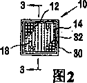
图2为示出图1中挠性光纤电缆端部套环的端视图;Figure 2 is an end view showing the ferrule at the end of the flexible fiber optic cable of Figure 1;
图3为穿过图1中光纤电缆端部的剖面图;Figure 3 is a cross-sectional view through the end of the fiber optic cable in Figure 1;
图4为本发明另一实施例的挠性光纤电缆端部的横向剖视图;4 is a transverse cross-sectional view of an end portion of a flexible optical fiber cable according to another embodiment of the present invention;
图5根据本发明的挠性光纤电缆端部的又一实施例的横向剖视图;Figure 5 is a transverse cross-sectional view of yet another embodiment of a flexible fiber optic cable end according to the present invention;
图6为示出涂层粘度与涂层厚度之间关系的曲线图。Figure 6 is a graph showing the relationship between coating viscosity and coating thickness.
具体实施方式Detailed ways
在下述说明中,为方便起见,使用特定术语并且不应该认为是对本发明的限定。术语“一个”定义为包括一个或多个参照项,除非特别说明。术语“阵列”这里包括任何类型的有序、二维光纤端部布置,例如挠性成像光纤束。In the following description, specific terms are used for convenience and should not be construed as limiting the present invention. The term "a" is defined to include one or more of the referenced item unless specifically stated otherwise. The term "array" here includes any type of ordered, two-dimensional arrangement of fiber ends, such as flexible imaging fiber bundles.
现在参照图1,示出挠性光纤电缆10。电缆10包括多个组在一起形成光纤束14的光纤12,光纤束14具有挠性中心部15和两个非挠性端部16、18,挠性中心部15内的光纤12可以相对于光纤束14内的相邻光纤12移动,非挠性端部16、18内的多个光纤12以预定的布置接合在一起,例如图2所示的布置。Referring now to FIG. 1 , a flexible fiber
如图3所示,每个非挠性端部16、18包括厚度基本一致的保护层20,其从向内与端部16、18的自由端24隔开的位置22开始在光纤束的外表面上延伸。优选保护层20为可以进行机加工的蜡,并且在一个优选实施例中为德国Offenbach的Loeffler GMBH公司生产的ISOLOX-TG。此类型的蜡一般用作防腐的保护蜡,但是发现它在本发明中非常有用。该蜡在80℃-90℃下融化,该温度高于在光纤束刻蚀工艺中通常使用的温度。尽管优选使用这种类型的蜡,根据本发明也可以使用其他类型的保护涂层或保护蜡。As shown in FIG. 3, each
优选利用浸蘸光纤束14的非挠性端部16、18的方式施加蜡。蜡涂层的厚度受到浸蘸工艺的影响。蜡越热,其粘度越低,蜡涂层越薄。涂层厚度与优选蜡的粘度之间的关系示于图6中。因此,可以在相当程度上控制蜡的厚度,使得涂层厚度大概为0.15mm成为可能。优选地,光纤束14上的蜡涂层的厚度大概为0.25mm至约5mm。更优选地,厚度在1mm-3mm范围内,更优选为1mm左右。施加保护层20后,去除或机加工去除端部16、18的自由端24与点22之间的保护层端部。The wax is preferably applied by dipping the
仍然参照图2和图3,套环30位于保护层20周围并与其干涉配合,使得端部16、18在套环30内居中。优选保护层20的外部横截面面积略大于套环30的内部横截面面积,因此二者间存在着干涉配合,并且需要施力来使光纤束14的端部16、18压入到相应的套环30内。在插入过程中将多余的蜡(或其他涂层材料)磨掉。优选地,套环30由金属制成。但是,它也可由合成材料制成,并且可以具有不同的内外截面,以便与光纤电缆端部16、18的几何形状相匹配。Still referring to FIGS. 2 and 3 , the
也可以利用具有的内部横截面不同于光纤束端部外部横截面的套环,如图4所示。图4中,使用圆形的套环40与方形横截面的光纤束14相连。由于横截面几何形状不同,只有光纤束14的涂蜡的角部与套环40的内表面接触。但是,这足以使光纤束14的端部16、18在套环40内居中。在以这种方式制造的示例中,制造方形横截面的光纤束14,其边缘长度约3mm。其居中安装在内径为4mm的圆形横截面的套环40内,套环的外径为6mm长度为2.5cm。A ferrule having an inner cross-section different from the outer cross-section at the end of the fiber bundle, as shown in FIG. 4, may also be used. In FIG. 4, a
再次参照图3,粘合剂32位于套环30与非挠性端部16、18之间,从向内与端部16、18隔开的位置到其自由端24。优选地,粘合剂为两种成分的环氧树脂,其具有在凝固时收缩最小的性质,以便防止从套环30内表面脱离。也可使用其他粘合剂,如丙烯酸或硅树脂。Referring again to FIG. 3 , adhesive 32 is located between
优选地,套环30的长度大于端部16、18的横向截面尺寸。例如,对于具有圆形横截面的光纤束,套环30的内径应该大于光纤束的直径。对于方形横截面或其他形状横截面的光纤束,套环的内部尺寸优选大于横穿其横截面的最大横向尺寸。这有助于确保光纤束端部16、18在套环30内居中。Preferably, the length of the
现在参照图5,示出光纤电缆10’另一个优选实施例,其中,光纤束端部16’、18’具有圆形横截面。套环40也为圆形横截面。蜡层20’具有足够的厚度,使得在安装套环40到光纤束端部16’、18’之上时,在蜡层20’与套环40的内表面之间产生干涉配合。Referring now to FIG. 5, another preferred embodiment of a fiber optic cable 10' is shown in which the fiber optic bundle ends 16', 18' have a circular cross-section. The
为了制造具有挠性中心部14和非挠性端部16、18的光纤电缆10,光纤束的端部16、18涂覆由厚度基本一致的蜡20。然后将一部分蜡层20从每个端部16、18从向内与每个端部16、18的自由端24隔开的位置22到其相应的自由端24之间去除。然后将每个端部16、18插入套环30、40内。套环与蜡层20的干涉配合导致端部16、18在安装时在相应的套环内居中。套环30、40粘结到相应的端部16、18,粘合剂32位于套环和相应的端部之间,从向内与每个端部16、18的自由端24隔开的位置22到其自由端24之间。To manufacture a
当光纤电缆10由玻璃光纤12的熔合束14形成时,所述光纤由可沥滤的隔离物隔开,在此情况下,沥滤电缆10的中心部14,以便溶解可沥滤的隔离物,使得中心部15内的光纤12可以彼此相对自由移动。为此,光纤电缆10由玻璃纤维或合成纤维制成时,端部16、18通过粘结工艺而保持在一起,并且不需要沥滤中心部。然而,在此情形下,由于消除了由于现有已知的利用合成纤维的卷缩壳体所导致的损坏,将套环30、40安装在端部16、18上也是有利的。When the
根据本发明的光纤电缆10、10’及其制造方法具有的优点是,不必挤压光纤束14的端部16、18周围的套环30、40。而且,涂层过程消除了光纤束10的横截面几何形状的微小不规则,并且产生了用于安装套环的光滑表面。通过监控施加蜡和蜡层20的外径,可以消除由于光纤束横截面变化导致的困难,并且可以实现光纤束14的端部16、18在套环30、40内的精度极高的准确定位,在生产中该精度可提供大约1%以内的对齐。
本发明基本说明了方形和圆形横截面的光纤束和套环,本领域技术人员将认识到光纤束端部可以具有多种横截面形状,也可以使用具有适当形状的套环。While the present invention generally describes square and circular cross-section fiber optic bundles and ferrules, those skilled in the art will recognize that a variety of cross-sectional shapes can be used at the end of the fiber bundle and that ferrules of appropriate shape can be used.
尽管详细说明了本发明的优选实施例,本发明但不局限于上述特定实施例,应当认为这只是示例性的。可以开发本发明的其他修改和延拓,所有这些修改都应当被认为是在由本发明后附权利要求所限定的范围内。While preferred embodiments of the invention have been described in detail, the invention is not limited to the particular embodiments described above, which should be considered as illustrative only. Other modifications and extensions of the invention may be developed, and all such modifications should be considered within the scope of the invention as defined by the appended claims.
Claims (15)
Applications Claiming Priority (2)
| Application Number | Priority Date | Filing Date | Title |
|---|---|---|---|
| US10/119,056 | 2002-04-09 | ||
| US10/119,056 US6775446B2 (en) | 2002-04-09 | 2002-04-09 | Flexible optic fiber cable with centered, interference fit ferrules |
Publications (2)
| Publication Number | Publication Date |
|---|---|
| CN1615447A CN1615447A (en) | 2005-05-11 |
| CN1288461C true CN1288461C (en) | 2006-12-06 |
Family
ID=29248236
Family Applications (1)
| Application Number | Title | Priority Date | Filing Date |
|---|---|---|---|
| CN03802088.2A Expired - Fee Related CN1288461C (en) | 2002-04-09 | 2003-03-10 | Flexible optic fiber cable with centered, interference fit ferrules |
Country Status (8)
| Country | Link |
|---|---|
| US (1) | US6775446B2 (en) |
| EP (1) | EP1493046B1 (en) |
| CN (1) | CN1288461C (en) |
| AT (1) | ATE364855T1 (en) |
| AU (1) | AU2003228292A1 (en) |
| DE (1) | DE60314386T2 (en) |
| RU (1) | RU2289832C2 (en) |
| WO (1) | WO2003087892A2 (en) |
Families Citing this family (3)
| Publication number | Priority date | Publication date | Assignee | Title |
|---|---|---|---|---|
| US7729582B2 (en) * | 2006-12-08 | 2010-06-01 | Wallac Oy | Fibre optic cable and method for producing the same |
| KR101091462B1 (en) * | 2009-01-16 | 2011-12-07 | 엘지이노텍 주식회사 | Optical module, optical printed circuit board and manufacturing method thereof |
| DE102011007878A1 (en) * | 2011-04-21 | 2012-10-25 | Karl Storz Gmbh & Co. Kg | Optical fiber device for an endoscope |
Family Cites Families (10)
| Publication number | Priority date | Publication date | Assignee | Title |
|---|---|---|---|---|
| US3624816A (en) | 1970-01-28 | 1971-11-30 | American Optical Corp | Flexible fiber optic conduit |
| US3830667A (en) | 1970-12-14 | 1974-08-20 | American Optical Corp | Method of making flexible fiberoptic bundles |
| GB1460548A (en) | 1975-11-20 | 1977-01-06 | Standard Telephones Cables Ltd | Optical fibre terminations and connectors |
| JPS59172605A (en) * | 1983-03-23 | 1984-09-29 | Olympus Optical Co Ltd | Terminal part reinforcing device for flexible optical fiber bundle |
| JPS60143307A (en) * | 1983-12-29 | 1985-07-29 | Sumitomo Electric Ind Ltd | Ferrule for optical connector |
| DE3620368A1 (en) | 1986-06-18 | 1987-12-23 | Schott Glaswerke | FIBER OPTICAL LIGHT GUIDE, HIGH-TEMPERATURE-RESISTANT IN ITS FACE AREA, AND METHOD FOR THE PRODUCTION THEREOF |
| US4984865A (en) * | 1989-11-17 | 1991-01-15 | Minnesota Mining And Manufacturing Company | Thermoplastic adhesive mounting apparatus and method for an optical fiber connector |
| US5013128A (en) | 1990-06-07 | 1991-05-07 | General Dynamics Corporation, Convair Division | Fiber optic light guide with improved end-to-end efficiency |
| US5386489A (en) * | 1993-01-05 | 1995-01-31 | Christine E. Munson | Deformable shape-retaining fiberoptic device |
| US6415085B1 (en) | 1995-08-01 | 2002-07-02 | At&T Corp. | Sub-miniature optical fiber cables, and apparatuses and methods for making the sub-miniature optical fiber cables |
-
2002
- 2002-04-09 US US10/119,056 patent/US6775446B2/en not_active Expired - Lifetime
-
2003
- 2003-03-10 WO PCT/US2003/007054 patent/WO2003087892A2/en active IP Right Grant
- 2003-03-10 DE DE60314386T patent/DE60314386T2/en not_active Expired - Lifetime
- 2003-03-10 AU AU2003228292A patent/AU2003228292A1/en not_active Abandoned
- 2003-03-10 EP EP03726040A patent/EP1493046B1/en not_active Expired - Lifetime
- 2003-03-10 AT AT03726040T patent/ATE364855T1/en not_active IP Right Cessation
- 2003-03-10 RU RU2004121672/28A patent/RU2289832C2/en active
- 2003-03-10 CN CN03802088.2A patent/CN1288461C/en not_active Expired - Fee Related
Also Published As
| Publication number | Publication date |
|---|---|
| DE60314386D1 (en) | 2007-07-26 |
| AU2003228292A1 (en) | 2003-10-27 |
| ATE364855T1 (en) | 2007-07-15 |
| EP1493046B1 (en) | 2007-06-13 |
| US20030202760A1 (en) | 2003-10-30 |
| DE60314386T2 (en) | 2008-02-14 |
| US6775446B2 (en) | 2004-08-10 |
| EP1493046A4 (en) | 2005-04-06 |
| WO2003087892A3 (en) | 2003-12-24 |
| CN1615447A (en) | 2005-05-11 |
| EP1493046A2 (en) | 2005-01-05 |
| WO2003087892A2 (en) | 2003-10-23 |
| AU2003228292A8 (en) | 2003-10-27 |
| RU2004121672A (en) | 2005-06-27 |
| RU2289832C2 (en) | 2006-12-20 |
Similar Documents
| Publication | Publication Date | Title |
|---|---|---|
| US11209594B2 (en) | Cable with overcoated non-coplanar groups of fusion spliced optical fibers, and fabrication method | |
| KR20070011330A (en) | Compact Optical Connectors with Thermoplastic Adhesive | |
| US5621835A (en) | Optical fiber assembly and manufacturing method for the same | |
| US20030099453A1 (en) | Hermetic fiber ferrule and feedthrough | |
| GB2193342A (en) | Connecting optical fibers | |
| US20160011373A1 (en) | Dual-polymer fiber optic interface with melt-bond adhesive | |
| CN1288461C (en) | Flexible optic fiber cable with centered, interference fit ferrules | |
| US11754786B2 (en) | Multi-fiber splice protector and cable assembly with intra-connector splices, and fabrication method | |
| CN1867847A (en) | Optical interconnect device | |
| EP2549315B1 (en) | Method, device and kit of parts for attaching an optical fiber in an optical fiber connector | |
| KR100970853B1 (en) | Fiber optic cable connector system | |
| JP2921462B2 (en) | Optical connector | |
| US20030190135A1 (en) | Hermetic waveguide seals and method of making them | |
| JP3191797B2 (en) | Optical fiber connector and method of manufacturing the same | |
| JP5281072B2 (en) | Optical connector and manufacturing method thereof | |
| JPS58216216A (en) | Method for assembling optical fiber connector | |
| EP0735391B1 (en) | Optical fiber assembly and manufacturing method for the same | |
| JP3795469B2 (en) | Optical connector | |
| JP2706908B2 (en) | Optical fiber assembly and method of manufacturing the same | |
| JPS60149015A (en) | optical connector | |
| JPH02153308A (en) | Optical fiber | |
| CN220171299U (en) | Optical fiber array | |
| JP2024101994A (en) | Fiber-optic splice and method for producing fiber-optic splice | |
| JPH0664213U (en) | Optical connector ferrule | |
| JP2012103311A (en) | Optical fiber with glass ferrule |
Legal Events
| Date | Code | Title | Description |
|---|---|---|---|
| C06 | Publication | ||
| PB01 | Publication | ||
| C10 | Entry into substantive examination | ||
| SE01 | Entry into force of request for substantive examination | ||
| ASS | Succession or assignment of patent right |
Owner name: SHORT PUBLIC CO., LTD. Free format text: FORMER OWNER: SCHOTT GLAS Effective date: 20050930 |
|
| C41 | Transfer of patent application or patent right or utility model | ||
| TA01 | Transfer of patent application right |
Effective date of registration: 20050930 Address after: Germany Mainz Applicant after: Schott AG Address before: Germany Mainz Applicant before: Schott Glas |
|
| C14 | Grant of patent or utility model | ||
| GR01 | Patent grant | ||
| CF01 | Termination of patent right due to non-payment of annual fee | ||
| CF01 | Termination of patent right due to non-payment of annual fee |
Granted publication date: 20061206 |