CN1286141C - Deflection coil with improved vertical deflection field - Google Patents
Deflection coil with improved vertical deflection field Download PDFInfo
- Publication number
- CN1286141C CN1286141C CNB001268961A CN00126896A CN1286141C CN 1286141 C CN1286141 C CN 1286141C CN B001268961 A CNB001268961 A CN B001268961A CN 00126896 A CN00126896 A CN 00126896A CN 1286141 C CN1286141 C CN 1286141C
- Authority
- CN
- China
- Prior art keywords
- coil
- window
- cathode ray
- ray tube
- deflection
- Prior art date
- Legal status (The legal status is an assumption and is not a legal conclusion. Google has not performed a legal analysis and makes no representation as to the accuracy of the status listed.)
- Expired - Fee Related
Links
Images

Classifications
-
- H—ELECTRICITY
- H01—ELECTRIC ELEMENTS
- H01J—ELECTRIC DISCHARGE TUBES OR DISCHARGE LAMPS
- H01J29/00—Details of cathode-ray tubes or of electron-beam tubes of the types covered by group H01J31/00
- H01J29/46—Arrangements of electrodes and associated parts for generating or controlling the ray or beam, e.g. electron-optical arrangement
- H01J29/70—Arrangements for deflecting ray or beam
- H01J29/72—Arrangements for deflecting ray or beam along one straight line or along two perpendicular straight lines
- H01J29/76—Deflecting by magnetic fields only
-
- H—ELECTRICITY
- H01—ELECTRIC ELEMENTS
- H01J—ELECTRIC DISCHARGE TUBES OR DISCHARGE LAMPS
- H01J29/00—Details of cathode-ray tubes or of electron-beam tubes of the types covered by group H01J31/00
- H01J29/46—Arrangements of electrodes and associated parts for generating or controlling the ray or beam, e.g. electron-optical arrangement
- H01J29/70—Arrangements for deflecting ray or beam
- H01J29/701—Systems for correcting deviation or convergence of a plurality of beams by means of magnetic fields at least
- H01J29/707—Arrangements intimately associated with parts of the gun and co-operating with external magnetic excitation devices
-
- H—ELECTRICITY
- H01—ELECTRIC ELEMENTS
- H01J—ELECTRIC DISCHARGE TUBES OR DISCHARGE LAMPS
- H01J29/00—Details of cathode-ray tubes or of electron-beam tubes of the types covered by group H01J31/00
- H01J29/46—Arrangements of electrodes and associated parts for generating or controlling the ray or beam, e.g. electron-optical arrangement
- H01J29/70—Arrangements for deflecting ray or beam
- H01J29/72—Arrangements for deflecting ray or beam along one straight line or along two perpendicular straight lines
- H01J29/76—Deflecting by magnetic fields only
- H01J29/762—Deflecting by magnetic fields only using saddle coils or printed windings
Abstract
The present invention relates to a electromagnetic deflection unit for colour cathode-ray tubes, comprising a pair of horizontal deflection coils and a pair of vertical deflection coils, the saddle-shaped vertical deflection coils having a rear bundle on the electron-gun side and a front bundle located on the screen side, lateral conductor harnesses connecting the two bundles so as to produce a main window in the intermediate region lying between these said bundles, the conductor harnesses being arranged so that, at the front end of the main window, on the screen side, the window extends over a radial angular aperture of greater than 38 DEG. This arrangement of the conductors in the rear part of the window makes it possible to minimize the vertical convergence errors between the red and blue beams, so as to avoid the use of additional field shapers to correct the said errors.
Description
Technical field
The present invention relates to a kind of arrangement for deflecting that is used for cathode ray tube, this arrangement for deflecting also is called deflector, comprises a pair of horizontal deflection coil and a pair of frame deflector coil, and two pairs of coils all are saddle type, and this special shape can reduce the coma error to greatest extent.
Background technology
Design to such an extent that make its cathode ray tube that produces chromatic image generally include an electron gun of launching three beams copline electron beam, each electron beam is intended to excite red, the green or blue corresponding fluorescent material of all kinds of a rule on the tube panel.
Electron beam scans tube panel under the influence of the deflection field that the level of the deflector that is fixed on neck and frame deflector coil produce.Usually be surrounded with the ring that a ferromagnetic material is made around the deflecting coil, its effect is that deflection field is focused on suitable position.
The three-beam electron-beam that electron gun produces must be focused at all the time on the tube panel otherwise will attract so-called convergence errors, and the concrete effect of this error is the representation process that upsets three looks.For making three beams copline electron-beam convergence, can adopt the deflection field that is called auto-convergence astigmatism deflection field as everybody knows.In automatic converged deflecting coil, the intensity of horizontal deflecting field distributes by pincushion, and the intensity of vertical deflection field is then by barrel-shaped distribution.
To be a kind of influence come out into the aberration of the electron beam on the both sides the three-beam electron-beam that delegation arranges from electron gun to coma, irrelevant with the curvature on the astigmatism of deflection field and tube panel surface.The electron beam on these both sides becomes low-angle to enter the deflection position with tube's axis, and also is subjected to another deflecting action except that the deflecting action that is subjected to electron beams.Coma normally enters at electron beam by revising deflection field that the distribution at deflector place is corrected, thereby the coma compensation of generation is distributed as draw the desired astigmatism of auto-convergence and needs to produce coma.Therefore, with regard to horizontal deflecting field, the deflection field at deflector rear portion is barrel-shaped, and anterior deflection field is pincushion.
Above-mentioned those shape can cause that error appears in the convergence of both sides electron beam, and this can find out that wherein red image has a skew along the test pattern vertical edge with respect to blue image from the test rectangle pattern that tube panel demonstrates.Change if linear mode is pressed in skew, might remedy by known method; On the contrary, if red/blue convergence errors value is non-linear along the variation of test pattern vertical edge, then also can remedy the phenomenon that this is called " vertical blue ripple " so far without any simple method.
In addition, these image geometry problems, coma problem and convergence problem are relevant with fluoroscopic plane performance and size.Generally make, adopt the cathode ray tube radius of curvature of spherical face little several years ago.In view of current trend is that only the suitable deflection field that produces by means of deflecting coil is controlled the problems referred to above and just become more and more difficult to the phosphor screen development greater than 70 centimetres of larger radius of curvature or flat fully, catercorner length.
The common practice is the position that deflection system is divided into three continuous actions along tube's axis: the more special difference coma that influences in rear of close electron gun, the more special astigmatism that affects deflection field in middle part, thereby influence is red and the convergence of blue beam, at last, the front of close tube panel influences the geometrical condition of the image that forms on the tube panel.
Summary of the invention
The objective of the invention is to solve the problem of " vertical blue ripple " and need not to set up any parts, more for example dispose to such an extent that make the sheet metal in the magnetic field that they can the one or more permanent magnets of local correction.This solution also provides further control measure and other performance of unlikely harm arrangement for deflecting, and a kind of correction of performance normally can make one or more other performance depreciations.
For achieving the above object, according to a kind of electro-magnetic deflection unit that is used for cathode ray tube of the present invention, comprise a pair of horizontal deflection coil and a pair of frame deflector coil, frame deflector coil is saddle type, frame deflector coil comprises forward part that is in the tube panel side and the rear section that is in electron gun side, these front and back two parts are joined to one another by the horizontal wire bundle, front and rear part and horizontal wire bundle form the window of no lead, this arrangement for deflecting is characterised in that, at the position near described rear section, window extends with the radially angular aperture Φ greater than 38 °.
Description of drawings
From following explanation and accompanying drawing other characteristics of the present invention as can be seen and advantage.In the accompanying drawing:
Fig. 1 shows the cathode ray tube that is equipped with according to deflector of the present invention;
Fig. 2 has schematically illustrated 1/4 part of color cathode ray tube screen, and can see has the aberration that is called " vertical blue ripple " on this part;
Fig. 3 is the end view according to coil of the present invention;
Fig. 4 shows an embodiment according to frame deflector coil of the present invention, can see the surface on it;
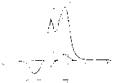
All harmonic waves that Fig. 5 shows the vertical deflection current potential that produces according to coil of the present invention are along the influence to described each coefficient of the particular arrangement of the situation of change of cathode ray tube main shaft and horizontal wire bundle lead.
Embodiment
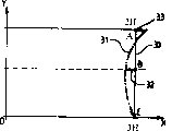
As shown in Figure 1, the cathode ray tube of auto-convergence colour display device is equipped with a glass bulb 6, and an end of glass bulb 6 disposes versicolor fluorescent material array, constitutes display screen 9, and the other end of glass bulb 6 disposes a cover electron gun 7.This cover electron gun disposes to such an extent that the three-beam electron-beam 12 of its generation is arranged in the horizontal direction, thereby encourages the wherein a kind of of shades of colour fluorescent material respectively.Electron beam is scanning fluoroscopic whole surface by means of arrangement for deflecting (or deflector) 1.Arrangement for deflecting is located on the neck 8 of cathode ray tube, form by a pair of horizontal deflection coil 3, a pair of frame deflector coil 4 and an iron core 5, each coil is isolated from each other with partition 2 and comes, and unshakable in one's determination 5 are made by ferromagnetic material, are intended to deflection field is focused on the site of action of design.
Within the scope of the invention, each frame deflector coil of deflector 1 is saddle type, and its part 19 that is called rear end part is near electron gun 7, and preferably open perpendicular to the direction extension of z axis on the edge.Another part 29 of coil 10 is called fore-end, and near display screen 9, and the deviation in driction z axis of the common crosscut z axis in edge curves inwardly.The fore-end 29 of saddle coil 10 is coupled together itself and rear end part 19 by horizontal wire 120 in groups.Each several part 19 and 29 and horizontal wire in groups 120 usually with respect to XZ plane symmetry configuration, form main window 18.Flow direction with the electronics that forms the three-beam electron-beam that comes out from electron gun 7 is a benchmark, the position of window 18 extended spots below is called middle part 24, each lead that forms forward part becomes the position of below, fan-shaped diffusing shape place to be called outlet position 23, and coil forms the rear section at window 18 rear portions position is called the position 25 that enters the mouth.
Fig. 2 shows the present invention and wants " vertical blue ripple " aberration of reducing.Demonstrate test pattern on fluoroscopic 1/4 part, can see the pattern drift phenomenon that red beam 30 and blue beam 31 produce.With first approximation, " vertical blue ripple " can be represented by following formula:
VBW=(ΔC+ΔA)/2-ΔB,
Wherein Δ A is the red/blue convergence errors at 3 o'clock, and Δ C is the convergence errors at 2 o'clock, and Δ B is 2 o'clock and 3 a Δs halfhour convergence errors between o'clock.
Fig. 3 shows the saddle coil of the implementing one aspect of the invention end view to one of them coil of 10.Each wire turn is formed by a lead frame that is saddle type usually.
Saddle coil above-mentioned and shown in Figure 4 can be used the fine copper wire coiling, and copper cash is wrapped with insulating material and thermosetting adhesive.Coiling is carried out on coil winding machine, with coil winding machine saddle coil is turned to its net shape basically, forms gap 21,21 ' etc. in the process of coiling.The shape in these gaps and position are determined by retractile pin 22 or plug-in unit 28.After the coiling, each saddle coil is fix in position in anchor clamps, it is exerted pressure, thereby draw desired mechanical dimension.This seasonal electric current lead of flowing through makes the thermosetting lead softening, again through supercooling, each lead is bonded together, and forms the self supporting type saddle coil.
Because each loop construction symmetry, thereby the deployable one-tenth the Fourier series of the number of ampere turns density of coil:
N (θ)=A
KCos (K θ), K=1,3,5,7, etc.
A wherein
K=(4/ π) ∫
Pi/2 0N (θ) cos (K θ) d θ
Ak is the coil harmonic wave.Current potential can be with the showing with numerical table of the number of ampere turns of axis till the θ, promptly
Φ(R,θ)=∫i·N(θ)·dθ
Coordinate R, the scalar potential of a some M can be represented by the formula among the θ:
Φ (R, θ)=Φ
K(R) sin (K θ), K=1,3,5,7, etc.
Wherein thereby R covers deflecting coil to make deflection field concentrate the radius of the ferromagnetic magnetic circuit that improves the arrangement for deflecting energy efficiency.
The wave amplitude Φ of K subharmonic
k(R)=(A
K/ K).
The intensity of the vertical deflection field of these auto-convergence deflectors is barrel-shaped distribution.And as everybody knows, the position that the convergence errors between redness and the blue beam can be by changing each lead of horizontal wire bundle is so that revise three times and/or five current potential harmonic waves are proofreaied and correct in the middle part 24 of frame deflector coil.These reasons make so far and frame deflector coil might be designed to such an extent that make its main window as far as possible little, this design is specially adapted to " vertical blue ripple " and equals or near zero occasion, but this loop construction can not solve red/blue convergence errors is along the situation of the vertical edge variation at visual 2 o'clock and 3 o'clock.
The present invention is intended to revise main window 18 near 7 times and 9 current potential harmonic waves in the front at outlet position 23.Thereby can only revise red/blue converged state by the configuration that changes each lead that constitutes horizontal wire bundle 120 and eliminate " vertical blue ripple " phenomenon.
Fig. 4 shows one embodiment of the present of invention, wherein shows the front view of frame deflector coil.
Therefore, here the front of the main window 18 of frame deflector coil is amplified compared with the prior art, thereby each lead near the intermediate location horizontal wire bundle between the part 24 and 24 of coil have at least 98% be in less than 71 ° radially angular aperture θ in, wherein θ is with respect to the separation plane YZ mensuration of two frame deflector coils.
Under the situation of phosphor screen diagonal greater than 70 centimetres large-scale cathode ray tube, empirical evidence θ preferably chooses the scope between 60 ° and 71 °, this as much as to say, near the position of fore-end, the radially angular aperture Φ extension of window (18) between 38 ° and 60 °.
For example, the diagonal of cathode ray tube is that 97 centimetres, phosphor screen form are 16/9 o'clock, and its frame deflector coil is that of Fig. 4 is a kind of, and the lead of horizontal wire bundle is in the front portion of main window 18 is in 67.5 ° radially angular aperture.
For controlling other parameter, no matter be the convergence situation or the geometrical condition of the image that forms on the phosphor screen, main window can its forward part contain the horizontal wire of fraction and unlikely influence red/the blue performance of assembling along visual vertical edge.Accomplish this point, the numbers of turn that are in the main window 18 must be little, is about 270 of total number of wire turns of constituting coil at most.
Below each table compared 1/4 phosphor screen with the result who is equipped with the deflector of looking technology frame deflector coil (being that the horizontal wire bundle disposes to such an extent that make main window 18 at the frame deflector coil that extends with 37 ° radially angular aperture near the position of fore-end) to measure to draw with the deflector that is equipped with frame deflector coil of the present invention (this cathode ray tube that refers to above-mentioned 97 cm diagonal lines is measured the result who draws).
The vertical coil of prior art is (red/the blue vertical coil of assembling by correction of the present invention
Error is represented with millimeter :)

As can be seen, the value of " vertical blue ripple " has reduced widely, is reduced to 0.62 millimeter from 1.16 millimeters.This correction is to carry out under the situation of comatic aberration that does not change image or geometrical condition.
Fig. 5 shows this and revises the influence that vertical magnetic field is produced.
Among Fig. 5,3 times, 5 times, 7 times of prior art coil deflection field vertical deflection current potential and 9 subharmonic are respectively with 41,51, and 61 and 71 mark, and 3 times, 5 times, 7 times of the above embodiment of the present invention frame deflector coil and 9 subharmonic are respectively with 40,50, and 60 and 70 mark.As can be seen, near the front at position 23, greater than 9 subharmonic, reduced widely afterwards when 7 subharmonic begin at main window, thus at the same level even smaller haply with 9 subharmonic on wave amplitude, described 7 times still opposite with 9 subharmonic symbols.
Consider other parameter in the design, certainly will carry out some correction near the rear section of intermediate location between the coil each several part 24 and 25 main window 18.When cathode ray tube is large-scale at least, empirical evidence, described window 18 in the radially aperture of its rear section still roughly greater than with the radially aperture that equals its forward part at least, thereby unlikely harm draw to " vertical blue ripple " and effect.
Therefore, in the embodiment of the cathode ray tube of 97 cm diagonal lines, optimum efficiency is that the radially aperture under window 18 following situations draws, promptly the horizontal wire bundle go the coil rear portion near each conductor configurations at outlet position in 65 ° angular aperture.
Claims (4)
1. electro-magnetic deflection unit (1) that is used for cathode ray tube, comprise a pair of horizontal deflection coil (3) and a pair of frame deflector coil (4), frame deflector coil (4) is saddle type, each frame deflector coil (4) comprises forward part (29) that is in the tube panel side and the rear section (19) that is in electron gun side, the horizontal wire bundle (120) that described front and back two parts extend with the direction that is parallel to cathode ray tube main shaft Z links together, front and rear part and horizontal wire bundle form the window (18) of no lead, it is characterized in that, at the position near described rear section, window (18) extends with the radially angular aperture Ф greater than 38 °.
2. according to the described electro-magnetic deflection unit of claim 1, it is characterized in that at the position near described forward part, described window (18) extends with the radially angular aperture Ф between 38 ° and 60 °.
3. the wherein arbitrary described electro-magnetic deflection unit that requires according to aforesaid right is characterized in that, at the position near described rear section, horizontal wire bundle (120) has at least 95% to be in less than in 80 ° the angular aperture Θ m.
4. cathode ray tube, its spy is characterised in that it comprises a wherein arbitrary described arrangement for deflecting according to the aforesaid right requirement.
Applications Claiming Priority (2)
| Application Number | Priority Date | Filing Date | Title |
|---|---|---|---|
| FR9910897A FR2797994B1 (en) | 1999-08-30 | 1999-08-30 | DEFLECTION UNIT FOR SELF-CONVERGING CATHODE RAY TUBE HAVING SEAT-SHAPED VERTICAL DEFLECTION COILS |
| FR99/10897 | 1999-08-30 |
Publications (2)
| Publication Number | Publication Date |
|---|---|
| CN1312580A CN1312580A (en) | 2001-09-12 |
| CN1286141C true CN1286141C (en) | 2006-11-22 |
Family
ID=9549417
Family Applications (1)
| Application Number | Title | Priority Date | Filing Date |
|---|---|---|---|
| CNB001268961A Expired - Fee Related CN1286141C (en) | 1999-08-30 | 2000-08-30 | Deflection coil with improved vertical deflection field |
Country Status (9)
| Country | Link |
|---|---|
| US (1) | US6577053B1 (en) |
| EP (1) | EP1081737B1 (en) |
| JP (1) | JP2001126639A (en) |
| KR (1) | KR100825144B1 (en) |
| CN (1) | CN1286141C (en) |
| DE (1) | DE60020312T2 (en) |
| FR (1) | FR2797994B1 (en) |
| MX (1) | MXPA00008464A (en) |
| MY (1) | MY119964A (en) |
Families Citing this family (3)
| Publication number | Priority date | Publication date | Assignee | Title |
|---|---|---|---|---|
| FR2791468B1 (en) * | 1999-03-24 | 2001-05-11 | Thomson Tubes & Displays | DEVIATION UNIT FOR SELF-CONVERGING CATHODE RAY TUBE WITH REDUCED TRAPEZE DIFFERENTIAL |
| US20040000858A1 (en) * | 2002-06-28 | 2004-01-01 | Samsung Electro Mechanics Co., Ltd. | Deflection yoke |
| US7838596B2 (en) | 2005-09-16 | 2010-11-23 | Eastman Chemical Company | Late addition to effect compositional modifications in condensation polymers |
Family Cites Families (10)
| Publication number | Priority date | Publication date | Assignee | Title |
|---|---|---|---|---|
| DE976695C (en) * | 1943-09-08 | 1964-03-05 | Philips Nv | Deflection coil arrangement for cathode ray tubes |
| US2562395A (en) * | 1949-02-23 | 1951-07-31 | Motorola Inc | Anastigmatic deflection yoke |
| GB1329412A (en) * | 1969-09-18 | 1973-09-05 | Science Res Council | Electrical coils for generating magnetic fields |
| US4039988A (en) * | 1973-07-23 | 1977-08-02 | U.S. Philips Corporation | Deflection coil having sections with minimum winding density portions and spaces |
| NL8802641A (en) * | 1988-10-27 | 1990-05-16 | Philips Nv | METHOD FOR MANUFACTURING A SADDLE DEFLECTION COIL FOR IMAGE DISPLAY AND DEFLECTION SYSTEM WITH SADDLE DEFLECTION COILS |
| SG93772A1 (en) * | 1989-10-31 | 2003-01-21 | Thomson Tubes & Displays | Color picture tube display device |
| FR2689679A1 (en) * | 1992-04-07 | 1993-10-08 | Thomson Tubes & Displays | Device for deflecting electron beams for self-converging cathode ray tubes and corrected in geometry. |
| FR2757681B1 (en) * | 1996-12-20 | 1999-01-29 | Thomson Tubes & Displays | DEFLECTION SYSTEM FOR CATHODE RAY TUBE SUITABLE FOR NORTH / SOUTH IMAGE GEOMETRY CONTROL |
| FR2757678B1 (en) * | 1996-12-20 | 1999-01-29 | Thomson Tubes & Displays | DEVIATION UNIT FOR AUTOCONVERGENT CATHODIC RAY TUBE WITH SADDLE-SHAPED DEVIATION COILS |
| KR100242172B1 (en) * | 1997-08-30 | 2000-02-01 | 김영남 | A film- and saddle-type deflection material of cathod ray tube and a method of manufacturing a saddle-type deflection coil using the same |
-
1999
- 1999-08-30 FR FR9910897A patent/FR2797994B1/en not_active Expired - Fee Related
-
2000
- 2000-08-18 US US09/641,602 patent/US6577053B1/en not_active Expired - Fee Related
- 2000-08-23 DE DE60020312T patent/DE60020312T2/en not_active Expired - Fee Related
- 2000-08-23 EP EP00402339A patent/EP1081737B1/en not_active Expired - Lifetime
- 2000-08-28 KR KR1020000050024A patent/KR100825144B1/en not_active IP Right Cessation
- 2000-08-29 MY MYPI20003964A patent/MY119964A/en unknown
- 2000-08-29 JP JP2000258364A patent/JP2001126639A/en active Pending
- 2000-08-29 MX MXPA00008464A patent/MXPA00008464A/en unknown
- 2000-08-30 CN CNB001268961A patent/CN1286141C/en not_active Expired - Fee Related
Also Published As
| Publication number | Publication date |
|---|---|
| MXPA00008464A (en) | 2002-07-22 |
| DE60020312T2 (en) | 2006-05-04 |
| EP1081737A1 (en) | 2001-03-07 |
| FR2797994A1 (en) | 2001-03-02 |
| KR20010021440A (en) | 2001-03-15 |
| JP2001126639A (en) | 2001-05-11 |
| FR2797994B1 (en) | 2001-12-07 |
| MY119964A (en) | 2005-08-30 |
| US6577053B1 (en) | 2003-06-10 |
| DE60020312D1 (en) | 2005-06-30 |
| KR100825144B1 (en) | 2008-04-24 |
| EP1081737B1 (en) | 2005-05-25 |
| CN1312580A (en) | 2001-09-12 |
Similar Documents
| Publication | Publication Date | Title |
|---|---|---|
| US6069546A (en) | Saddle shaped deflection winding having a winding space | |
| US6150910A (en) | Deflection yoke with geometry distortion correction | |
| CN1286141C (en) | Deflection coil with improved vertical deflection field | |
| CN1227707C (en) | Deflection device comprising saddle-shape vertical deflection coil for cathode-ray tube | |
| CN1263075C (en) | Delfection unit for self-conveying cathode-ray tubes with reduced trapezoid differential | |
| EP0569079B1 (en) | Combination of display tube and deflection unit comprising line deflection coils of the semi-saddle type with a gun-sided extension | |
| US7005788B2 (en) | Magnetic device for correcting image geometry defects for cathode-ray tubes | |
| KR100482942B1 (en) | A saddle shaped deflection winding spaces in the rear |
Legal Events
| Date | Code | Title | Description |
|---|---|---|---|
| C06 | Publication | ||
| PB01 | Publication | ||
| C10 | Entry into substantive examination | ||
| SE01 | Entry into force of request for substantive examination | ||
| C10 | Entry into substantive examination | ||
| SE01 | Entry into force of request for substantive examination | ||
| C14 | Grant of patent or utility model | ||
| GR01 | Patent grant | ||
| C17 | Cessation of patent right | ||
| CF01 | Termination of patent right due to non-payment of annual fee |
Granted publication date: 20061122 Termination date: 20100830 |