CN1281530C - Method and apparatus for blowing and taking out glass container - Google Patents
Method and apparatus for blowing and taking out glass container Download PDFInfo
- Publication number
- CN1281530C CN1281530C CNB031412874A CN03141287A CN1281530C CN 1281530 C CN1281530 C CN 1281530C CN B031412874 A CNB031412874 A CN B031412874A CN 03141287 A CN03141287 A CN 03141287A CN 1281530 C CN1281530 C CN 1281530C
- Authority
- CN
- China
- Prior art keywords
- built
- container
- shower head
- head mechanism
- type
- Prior art date
- Legal status (The legal status is an assumption and is not a legal conclusion. Google has not performed a legal analysis and makes no representation as to the accuracy of the status listed.)
- Expired - Fee Related
Links
Images


Classifications
-
- C—CHEMISTRY; METALLURGY
- C03—GLASS; MINERAL OR SLAG WOOL
- C03B—MANUFACTURE, SHAPING, OR SUPPLEMENTARY PROCESSES
- C03B9/00—Blowing glass; Production of hollow glass articles
- C03B9/30—Details of blowing glass; Use of materials for the moulds
- C03B9/36—Blow heads; Supplying, ejecting or controlling the air
- C03B9/3663—Details thereof relating to internal blowing of the hollow glass
- C03B9/3672—Details thereof relating to internal blowing of the hollow glass using a tube
-
- C—CHEMISTRY; METALLURGY
- C03—GLASS; MINERAL OR SLAG WOOL
- C03B—MANUFACTURE, SHAPING, OR SUPPLEMENTARY PROCESSES
- C03B9/00—Blowing glass; Production of hollow glass articles
- C03B9/30—Details of blowing glass; Use of materials for the moulds
- C03B9/36—Blow heads; Supplying, ejecting or controlling the air
- C03B9/3618—Means for holding or transferring the blow head
-
- C—CHEMISTRY; METALLURGY
- C03—GLASS; MINERAL OR SLAG WOOL
- C03B—MANUFACTURE, SHAPING, OR SUPPLEMENTARY PROCESSES
- C03B9/00—Blowing glass; Production of hollow glass articles
- C03B9/30—Details of blowing glass; Use of materials for the moulds
- C03B9/44—Means for discharging combined with glass-blowing machines, e.g. take-outs
- C03B9/447—Means for the removal of glass articles from the blow-mould, e.g. take-outs
Landscapes
- Engineering & Computer Science (AREA)
- Chemical & Material Sciences (AREA)
- Manufacturing & Machinery (AREA)
- Materials Engineering (AREA)
- Organic Chemistry (AREA)
- Blow-Moulding Or Thermoforming Of Plastics Or The Like (AREA)
- Containers Having Bodies Formed In One Piece (AREA)
- Specific Conveyance Elements (AREA)
Abstract
Vertically aligned first and second combined blowhead and takeout mechanisms are provided to sequentially blow glass parisons into containers in a mold set and to transfer blown containers to a deadplate of a glass containing forming machine. Each of the combined mechanisms is pivotally suspended about an axis A from a carrier arm that is pivotally attached to an end of an oscillating arm, an opposed end of which is pivoted about an axis. The axis of each combined blowhead and takeout mechanism is periodically raised and lowered to permit the other combined blowhead and takeout mechanism to oscillate therebeneath, to thereby permit overlapping cycles between the blowhead and takeout mechanisms. Each blowhead and takeout mechanism is provided with a chuck or tong assembly to engage or release each container by its finish. Each tong assembly has a plurality of tong elements that are simultaneously moved radially in or out by oscillation of a cam that has a non-circular slot in which a pin carried by each tong element rides.
Description
Technical field
The present invention relates to a kind ofly be used at the mould blow-molded glass container of glass ware formation machine and from this mould, take out the method and apparatus of blown container.More particularly, the present invention relates to a kind of method and apparatus, it is used for the blowing mould blow-molded glass container at I.S. (determinant) glass ware formation machine, from then on take out in the mould afterwards blown container and blown container be sent on the dead plate of machine so that cool off and finally take out to be for further processing.
Background technology
The United States Patent (USP) 3472639 (Mumford) and 4427431 (people such as Mumford) that transfers the predecessor of present assignee has generally been introduced by the known machine of I.S. machine type and has been made Glass Containers, and the disclosure of these patents is all incorporated herein by reference.As that introduce by these documents or otherwise known, the I.S. facility have a plurality of stations side by side, be generally six, eight, ten or even 12 stations, on each station by two the step operations come container molding.In first operation, come the preformed member that moulding is one or more, be generally three or four containers by blowing or press working, it is commonly referred to parison or blank.The moulding on inverted direction of these preformed members, promptly its opening end down, they have the main part of moulding in being commonly referred to the assembling die of blank mould.The mouth of the held lid of threaded or other appropriate configuration of this preformed member is in independent die for molding, and this mould is commonly referred to eck mould or neck ring, its in the molding process of parison, be positioned at the combination blank mould near.
After the molding process of parison is finished, open assembling die, after the parison by the eck mould clamping, and by its camber line upset along 180 ° is sent on the combination blowing mould, so that parison is blow molded into container.The upset operation realizes by rotating the trip shaft of having fixed the eck mould arm it on sliding type, thus make parison in the blowing process uprightly, promptly its opening end is up.Parison or the blank roughly introduced Glass Containers in common United States Patent (USP) of transferring the possession of 5893942 people such as () Nickey and 6098427 (Kirkman) are sent to the blowing mould of I.S. machine as described above from blank mould, and the disclosure of these patents is all incorporated herein by reference.
Say traditionally, as explaining in the predecessor's who transfers present assignee the United States Patent (USP) 3630709 (Irwin), in the blowing mould of I.S. machine, come blown container by shower nozzle, shower nozzle move to be in given I.S. machine station on blowing mould in parison form blowing and engage, move to then not therewith that the blown container at blowing mould place engages, the disclosure of this patent is incorporated herein by reference.The container that to blow by unloading device after opening assembling die takes out from blowing mould, and unloading device is equipped with a plurality of clamps, and each is organized clamp and is respectively applied for each blowing mould on the I.S. machine station relevant with unloading device.The common United States Patent (USP) 6241448B1 (Nicholas) that transfers the possession of has introduced roughly aforesaid unloading device, and it is used for taking out blown container from the mould of I.S. machine station, and the disclosure of this patent is incorporated herein by reference.United States Patent (USP) 5807419 (people such as Rodriquez-Wong) has been introduced the I.S. machine of function combinations in a mechanism of a kind of shower nozzle and unloading device.Yet, mechanism in the documents of ' 419 has described and has used traditional pivotable clamp (part 72,73) below ball, engage with each container, ball is called the transmission pearl, it is positioned under the closing in of threaded or other structure of container, and this just requires to clamp blown container so that should open the combination blowing mould before taking out at clamp.For above-mentioned ' reason described in the 488B1 patent, the requirement that should open blowing mould before clamp clamps blown container is the temporal shortcoming of machining.
Summary of the invention
According to the present invention, a kind of built-up type shower nozzle/unloading device of the I.S. of being used for glass ware formation machine is provided, and a kind of method of from this mould, taking out at the blowing mould blow-molded glass container of this glass ware formation machine and the container that will blow of being used for.This device comprises the container closing in splice chucks of each container that is used on the station of I.S. machine moulding simultaneously, and that each chuck comprises is a plurality of, the part of three circumferentially spaceds preferably, and it is shift-in and shifting out so that close up and engage with container by container uniformly.Like this, container can engage with chuck, simultaneously wherein the assembling die of blown container still remain closed, thereby allow when opening container, can take out container immediately in the assembling die of the blow molding machine of moulding wherein so that be sent on the dead plate of I.S. machine.The cycling time of the loss that exists in this has just eliminated at the withdrawing device of some prior aries such as the above-mentioned described device of ' 419 patent, in these devices, the container that has the transmission pearl with need to open assembling die before withdrawing device engages.
In a preferred embodiment of the invention, on each station of I.S. machine, all be provided with a pair of built-up type shower nozzle/unloading device.This combined mechanism is carried out timing alternately to be operated making it, therefore a combined mechanism can be arranged in blown container in the blowing mould of machine, and another combined mechanism is arranged in and turns back to the blowing mould place immediately after leaving in blown container on the dead plate of machine, thereby begins to repeat the blowing circulation.This has just eliminated the cycling time of caused loss in the I.S. machine that only has a shower nozzle on each machine station, because blowing circulation must place on the dead plate of machine and after returning and could begin at shower nozzle blown container.Bump in operating process for fear of independent combined mechanism, the pivot of the pivot swivel arm of each combined mechanism is movable on a vertical plane, thus can with enter combined mechanism be positioned at leave combined mechanism its will be blown container be sent to from blowing mould on the height that can reach the pivot rotation process on the dead plate of machine.Use a pair of built-up type shower nozzle/unloading device to improve the cycling time of moulding by this way, this be because it guaranteed when mould around the parison that is sent to the mould place during closure, exist a built-up type shower nozzle/unloading device to be positioned at the blowing mould place, and do not need to wait for that shower nozzle returns from dead plate after the container that will before blow is placed on the dead plate of machine.
Therefore, an object of the present invention is to provide a kind of improved apparatus and method, be used for the parison of plastic glass being blow molded into container, and blown container is sent to the different positions so that further handle from blowing mould at the blowing mould of glass ware formation machine.More particularly, the purpose of this invention is to provide a kind of improved method and apparatus with above-mentioned feature, wherein parison is blown in the blowing mould of I.S. formula glass ware formation machine, is sent to then on the dead plate of I.S. machine, so that cool off and finally be further processed.
In order further to understand the present invention and purpose thereof, should read accompanying drawing and following cutline, embodiment and claims.
Description of drawings
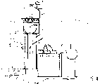
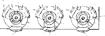
Fig. 1-the 6th has shown the schematic elevational view when device according to the present invention is in different positions during its operation cycle;
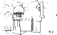
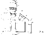
Fig. 7 is the front view of magnification ratio of the part of Fig. 1-6 shown device;
Fig. 8 is the sectional view along Fig. 7 center line 8-8;
Fig. 9 is the sectional view along Fig. 7 center line 9-9;
Figure 10 is the sectional view along Fig. 7 center line 10-10;
Figure 11 A, 11B have constituted jointly along the upper view and the lower view of the magnification ratio of Fig. 7 center line 11-11;
Figure 12 is the sectional view along Fig. 7 center line 12-12;
Figure 13 is the decomposition diagram of the part of Fig. 7-12 shown device; With
Figure 14 is the decomposition diagram of magnification ratio of another part of Fig. 1-6 shown device.
Embodiment
As being schematically shown among Fig. 1-6, the station 20 of the I.S. machine that partly illustrates is provided with one group of blowing mould 22, but the blank or the parison P of the glass composition of blow molding under suitable high temperature can be blow molded into container C therein.Fig. 1-6 has shown three containers of moulding in each group blowing mould, is designed to make simultaneously four containers of as many as (" four bottles " machine) or even few I.S machine to a container yet should be appreciated that the present invention also is applicable on each machine station.Under any circumstance, as understanding in the art, each is organized blowing mould 22 and is made of one group of relative assembling die, and assembling die is periodically opened each other by anti-swing or anti-translational motion or be closed, thereby has formed the die cavity that is used for each container C moulding when closure.
As special demonstration the among Fig. 5, the parison P that will be shaped to container C in mould 22 is sent on the mould 22 by the blank molding side of eck mould 24 from the machine station.Eck mould 24 is carried by upset or eck mould arm component 26, and it is connected in the upset or eck mould axle 28 that can swing, and axle 28 is commonly referred to weighshaft, its can be between position shown in Figure 1 and position shown in Figure 5 along 180 ° circular swing motion.After being sent to parison P in the mould 22, invert arm assembly 26 and the eck mould 24 that carries thereof are just got back to Fig. 5 position from Fig. 1 position, so that therefrom take out after the blown container C, begin to repeat the Glass Containers manufacturing processed in mould 22.
I.S. the station 20 of machine is provided with a pair of built-up type shower nozzle/ unloading device 30,32 side by side, and each mechanism all has 34, one this shower nozzles 34 of a plurality of independent shower nozzles and is used in container C of mould 22 moulding.In Fig. 7-13, shown the shower head mechanism 30 that is positioned at position shown in Figure 6 in detail, yet should be appreciated that shower nozzle 32 has the structure identical with shower nozzle 30.Under any circumstance, each shower head mechanism 30,32 is formed by load bearing arm 36 and swing arm 38, and shower nozzle 34 overhangs out from load bearing arm 36, and load bearing arm 36 is suspended on the swing arm 38, thereby can be pivotable with respect to swing arm 38 around axle A.Each load bearing arm 36 can rotate with respect to swing arm 38 pivots of shower head mechanism 30 or 32, its main points are that the equivalent structure by parallel connection mechanism or other known way guarantees when swing arm 38 swings, when for example swinging to its position among Fig. 6, can not change by the position, angle of the entrained shower nozzle 34 of load bearing arm 36 from the position of shower head mechanism shown in Figure 1 30.
The position that Fig. 1 has shown shower head mechanism 32 thereby can be placed on it blown container C just on the dead plate 40 of I.S. machine station 20.Under this state of device, shower head mechanism 30 is positioned to vertically align with pylon 42, and shower head mechanism 30 is fixed on the pylon 42 and rotates so that carry out pivot around axle B.Equally, shower head mechanism 32 is fixed on the second pylon (not shown) so that carrying out pivot around axle B rotates, and second pylon is right after and also forms mirror image with it pylon 42 after.About this point, each shower head mechanism 30,32 pivot B can be in low level, for example Fig. 1 vertically moves between the shower head mechanism 32 residing high positions among shower head mechanism 32 residing positions and Fig. 4 by the structure that will be explained in greater detail below, thereby allow shower head mechanism 30,32 swing between position shown in Figure 1 and position shown in Figure 4, and can not disturb the contact between the shower head mechanism 30 and 32 that aligns in same vertical plane.Like this, when shower head mechanism 30 in the stroke that container C is placed on the dead plate 40, the shower nozzle 34 of shower head mechanism 32 just will be positioned to engage with parison P in the mould 22, this for example can find out from the comparison between Fig. 4 and 6.Compare with the installation situation of only using a shower nozzle/unloading device, this can allow to exist the minimizing that about 13% substance calculates the cycling time container C to take next group away from mould 22 taking one group of container C away from mould 22, and, can not reduce the cooling time of the container C on the dead plate 40 taking out part refrigerative container C from dead plate 40 to hold new container molding C before the transmission of dead plate 40.Perhaps, can reduce to act on mass force on the blown container C by mobile shower nozzle 30,32 more lentamente, thereby reduce the raising of cycling time to a certain extent.In any case, if each can engage with blown container C by closing up built-up type shower nozzle/unloading device before the split mold of opening mould 22, the minimizing of cycling time can improve about 4% so, that is to say, can reduce about 17% altogether, need not joint with container C simultaneously and be deferred to and open till the assembling die, it is necessary that this delay engages under the situation that transmits blown container from mould 22 that is realized on the transmission pearl of the clamp by traditional unloading device.Introduced this phenomenon above-mentioned in the B1 patent of ' 488.In addition, use shower nozzle blown container C be sent to and allow on the dead plate 40 to come partly cooling vessel C in shower nozzle 30 or 32 by in transmitting operation, air being blown into.
As shown in Figure 7, shower head mechanism 30 has the roughly trapezoid framework 44 that has carried shower nozzle 34, and each shower nozzle 34 can pass through separation member 35 (Figure 11 B) and break away from apace with framework 44.Framework 44 is provided with the circular groups component 46 that extends through from framework 44, it is parallel to the orientation of the entrained container C of shower nozzle 30 and is positioned at its top.Be provided with the oppositely pneumatic cylinder 48 of bidirectional-movement between the end of annular element 46, pneumatic cylinder 48 can drive the assembled rack 50 (Fig. 8) that extends through annular element 46 from opposed end.But to-and-fro movement but non-rotatable tooth bar 50 engage with the screw rod 52 relevant with each shower nozzle 34 in the mode of right angle drive, so that open or close the container relevant with each shower nozzle 34 close up joint clamp or chuck assembly 54 (Fig. 9,10) simultaneously.
As Fig. 7, shown in the 11A, framework 44 is made of the upper-part 56 that is fixed on the general triangular on the lower member 58 with screw thread or other adjustable mode, is provided with strongback 57 between them, is used to guarantee wherein have the upper-part 56 of aligning opening and the correct aligning between the lower member 58.Upper-part 56 is fixed on the swing arm 38, so that swing between position shown in Fig. 3 and 4 and position shown in Figure 6 with swing arm 38, lower member 58 has the parts relevant with each shower nozzle 34.As shown in figure 12, the cooling air that is used for cooling off each shower nozzle 34 circulates by the passage 60 of lower member 58, and be used at Fig. 3, the blowing air that in the position of shower head mechanism shown in 4 30 parison P is blow molded into container C is then introduced by the passage in the lower member 58 62.The air that is used to operate the pneumatic cylinder 48 of the cylinder body that is shown as the setting of pair of end opposite end is in the drawings introduced by entering pipeline 64, enters pipeline 64 and receives from the passage 64a in the lower member 58, the air among the 64b.Blowing air from passage 62 is blown among the parison P that just is being blown to container C downwards by transfer tube 66, the upper end of transfer tube 66 is compressed spring 68 downward fexible bias pressures, and is provided with O-ring seals 70 to allow on the expansion of transfer tube 66 and the sliding motion that realization seals between the passage of the upper end that accommodates transfer tube 66 in the lower member 58.The lower end of transfer tube 66 is placed in the upper end of blowing air admission pipe 72 (Figure 11 B), enters pipe 72 and extends among the parison P or container C that engages with the shower nozzle 34 relevant with air admission pipe 72, and this decides as the case may be.
Each grip module 54 have circumferentially isolated a plurality of, as shown be three clamp member 74, they can be driven simultaneously, or radial inward moves the closing in F (Figure 11 B) with grip containers C, or move outwardly to discharge the closing in F of container C.Have a closing in F who is used for applying top cover on container C though container C is shown as, yet it is contemplated that, the junction surface of the closing in F of clamp member 74 can be constructed to be permeable to come operation vessel C by screw thread closing in F.About this point, each clamp member 74 is clamped in the clamp seat 75, and has upwardly extending pin 76, and it is contained in the ring cam set follower 77, and pin 76 is cross-placed in the non-circular slot 78 of salient angle of swing cam 80.The swing of the cam 80 that is caused by the flexible of assembled rack 50 can be effectively moves to the clamp member 74 of each grip module 54 simultaneously to form with the closing in (F) of container (C) and engages or be disengaged.The assembly that comprises clamp member 74 and clamp body 76 can slide in annular clamp shell 79, and can limit the backward travel of this assembly by its position along the adjustable pin 81 of its longitudinal center's axis.
The screw rod 52 of each shower nozzle 34 is fixed on the annular element 82 of transfer tube 66, in the cavity 86 of shower head mechanism 30, be provided with lining 84, it is positioned at the place, opposite end of transfer tube 82, and is moving around the vertical central axis string pendulum of transfer tube 66 together to allow itself and screw rod 52 and transfer tube 66.The bottom of transmission pipeline 66 is provided with externally threaded connector 86, has can be fixed on the outside of connector 86 by screw thread at the cam 80 of the upright annular section 80a of lining 88 internal rotation, thereby can rotate therewith.Cam 80 also can be fixed on the extension of top 72a of air admission pipe 72 by screw thread, thereby can rotate therewith; Like this, the to-and-fro movement of assembled rack 50 can make screw rod 52 swings effectively, thereby makes cam 80 swings, so that clamp member 74 moves in or out as required.Yet, also be provided with round the annular stop assembly 90 of a part of upstanding portion 80a of cam 80, thereby can stop the swing of cam 80 when needed.
Figure 14 has shown the device that is used to lift or reduce the axle of shower head mechanism 30,32, and it is called as lower shaft A hereinbefore.Figure 14 has shown especially this device about shower head mechanism 30, and this device pylon 42 pivotally fixed thereon, yet should be appreciated that the device that is used to lift or reduces shower head mechanism 32 is identical with the used device of shower head mechanism 30 on design and structure.Cam 38 is driven by tooth bar 92 around the swing of axle B, and the translational motion of tooth bar 92 is driven by reversible motor 94, and it preferably is used to realize the AC servo motor of best controllability.The gear assembly 95 that the swing of electric motor 94 causes sliding up and down on ball spline 99 produces swing, and ball spline 99 extends to gear assembly 95 from electric motor 94.Tooth bar 92 drivings are fixed on the spurn wheel 96 on the axle 98, and an axle B extends through axle 98, and arm 38 is connected on the axle 98 to rotate with axle 98.
Though shown hereinbefore and introduced applicant's design till the applying date for realizing optimal mode of the present invention, yet for a person skilled in the art should be clear, without departing from the scope of the invention, can carry out suitable modification, variation and equivalent process to the present invention, scope of the present invention is only limited by the clause and the legal equivalents thereof of following claim.
Claims (9)
1. a built-up type that is used for glass ware formation machine takes out and nozzle component, and described built-up type takes out and nozzle component comprises:
First built-up type takes out and shower head mechanism, and it is used for blowing gas is injected in first group of Glass Containers that the mould of described shaper is blown, and clamps described first group of container then;
The first pivot swivel arm, described first built-up type takes out and shower head mechanism is mounted close to the free end of the described first pivot swivel arm, and away from the pivot of the described first pivot swivel arm;
Be used to make the device of described first pivot swivel arm swing, its described first built-up type is taken out and shower head mechanism and the mould of described shaper in Glass Containers aligned position and and the dead plate aligned position of described shaper between move;
Be used to promote and reduce the device of the pivot of the described first pivot swivel arm;
Second built-up type takes out and shower head mechanism, and it is used for blowing gas is injected in second group of Glass Containers that the mould of described shaper is blown, and clamps described second group of container then;
The second pivot swivel arm, described second built-up type takes out and shower head mechanism is mounted close to the free end of the described first pivot swivel arm, and away from the pivot of the described second pivot swivel arm;
Be used to make the device of described second pivot swivel arm swing, its described second built-up type is taken out and shower head mechanism and the mould of described shaper in second group of Glass Containers aligned position and and the dead plate aligned position of described shaper between move;
Be used to promote and reduce the device of the pivot of the described second pivot swivel arm;
It is characterized in that, when the Glass Containers aligned position in one in described first pivot swivel arm and the described second pivot swivel arm mould that moves to described shaper, described one in the pivot of the pivot of the described first pivot swivel arm and the described second pivot swivel arm is lifted with respect in the pivot of the pivot of the described first pivot swivel arm and the described second pivot swivel arm another, with avoid in the swing process of the swing process of the described first pivot swivel arm and the described second pivot swivel arm described first built-up type taking-up and shower head mechanism and described second built-up type takes out and shower head mechanism between come in contact.
2. device according to claim 1 is characterized in that, described first built-up type takes out and shower head mechanism comprises:
Chuck, it has the circumferential isolated a plurality of chuck spares that are provided with annular array, described chuck spare only on the horizontal plane around the closing in of Glass Containers but the first location that does not contact with described Glass Containers and and the contacted second position of closing in of described Glass Containers between mobile simultaneously; With
The device that is used to make described chuck spare between the described first location and the second position, to move simultaneously.
3. device according to claim 2 is characterized in that, the described device that is used to described chuck spare is moved between the described first location and the second position simultaneously comprises:
Ring cam set has the circumferentially non-circular slot of isolated a plurality of double ends in the described ring cam set, a described non-circular slot is corresponding to a described chuck spare;
Wherein, each described clamp member all has pin, and it is contained in the non-circular slot of described cam; With
Be used to make the device of described cam swing, its pin that makes each described clamp member is contained in a position in wherein the non-circular slot from it and moves to it and be contained in the second position in wherein the non-circular slot.
4. device according to claim 3 is characterized in that, is used to make the described device of described cam swing to comprise:
Tooth bar;
Move the device of described tooth bar with linear fashion; With
Relevant with each described cam member and with described tooth bar meshed gears, be used on the common circumferential direction, making simultaneously each described gearing.
One kind be used for the mould blow-molded glass container of glass ware formation machine and blown container be sent to method on the dead plate of described glass ware formation machine from described mould, described method comprises:
Provide first built-up type to take out and shower head mechanism;
When first group of container is in the described mould, air is injected in described first group of container, so that the preformed member of described container is blow molded into container by described first built-up type taking-up and shower head mechanism;
Take out and shower head mechanism clamps described first group of blown container by described first built-up type;
Will by described first built-up type take out and the shower head mechanism clamping described first group the blow-molded glass container be sent on the dead plate, and with described first group the blow-molded glass container be released on the described dead plate;
Provide second built-up type to take out and shower head mechanism;
When second group of Glass Containers is in the described mould, air is injected in described second group of container of in the mould of described shaper, blowing, by described second built-up type taking-up and shower head mechanism so that the preformed member of described container is blow molded into container;
Take out and shower head mechanism clamps described second group of blown container by described second built-up type; With
It is characterized in that:
A) described first built-up type is taken out and shower head mechanism remains in the same vertical plane with described second built-up type taking-up and shower head mechanism;
B) described first built-up type is being taken out and shower head mechanism is sent to from described blowing mould the process on the described dead plate, described second built-up type is taken out and shower head mechanism is sent on the described blowing mould from described dead plate, and can not cause the described first built-up type taking-up and shower head mechanism and the taking-up of described second built-up type and shower head mechanism to come in contact.
6. method according to claim 5 is characterized in that, described method also comprises:
Reversibly lift in taking-up of described first built-up type taking-up and shower head mechanism and described second built-up type and the shower head mechanism, another in described first built-up type taking-up and shower head mechanism and taking-up of described second built-up type and the shower head mechanism then is sent to container on the described dead plate.
7. method according to claim 5 is characterized in that, described method also comprises:
When being sent to described container on the described dead plate, air is injected constantly the container that is transmitted by described first built-up type taking-up and shower head mechanism; With
When being sent to described container on the described dead plate, air is injected constantly the container that is transmitted by described second built-up type taking-up and shower head mechanism.
8. clamp mechanism, the Glass Containers that stands vertically that its mould that is used for being clamped in glass ware formation machine is blown, described clamp mechanism comprises:
Chuck, it has a plurality of chuck spares that make progress in week with the annular array setting, described chuck spare only on the horizontal plane around the closing in of Glass Containers but the first location that contact with described Glass Containers and and the contacted second position of closing in of described Glass Containers between mobile simultaneously; With
The device that is used to make described chuck spare between the described first location and the second position, to move simultaneously.
9. one kind is used for having the method for the container of blow-molded glass that stands vertically of closing in from the blowing mould taking-up of glass ware formation machine, described closing in is positioned on the described blowing mould, described blowing mould comprises a pair of discerptible half module, described half module is closed each other in the molding process of Glass Containers, and after molded the finishing of described Glass Containers, open each other, to allow taking out blown glass container from described blowing mould, described method comprises:
Chuck is provided, and described chuck has the chuck spare of a plurality of circumferential settings, and described chuck spare is only moving between the first location of outermost radially and the radially interior second position on the horizontal plane simultaneously;
Described chuck is positioned to the closing in of the Glass Containers in the described blowing mould, and the closed and described chuck spare of described half module this moment is in its first location place;
When described half module is closed, make described chuck spare move to its second position place simultaneously, thereby engage with the closing in of Glass Containers in the described blowing mould; With
Open the half module of described blowing mould afterwards, and described chuck is moved with respect to described blowing mould, thereby from described blowing mould, take out described Glass Containers.
Applications Claiming Priority (2)
| Application Number | Priority Date | Filing Date | Title |
|---|---|---|---|
| US10/161966 | 2002-06-03 | ||
| US10/161,966 US6848273B2 (en) | 2002-06-03 | 2002-06-03 | Apparatus for blowing and removing glass containers |
Publications (2)
| Publication Number | Publication Date |
|---|---|
| CN1468820A CN1468820A (en) | 2004-01-21 |
| CN1281530C true CN1281530C (en) | 2006-10-25 |
Family
ID=29583525
Family Applications (1)
| Application Number | Title | Priority Date | Filing Date |
|---|---|---|---|
| CNB031412874A Expired - Fee Related CN1281530C (en) | 2002-06-03 | 2003-06-03 | Method and apparatus for blowing and taking out glass container |
Country Status (13)
| Country | Link |
|---|---|
| US (3) | US6848273B2 (en) |
| EP (1) | EP1380546A3 (en) |
| JP (1) | JP2004026642A (en) |
| CN (1) | CN1281530C (en) |
| AR (1) | AR040103A1 (en) |
| AU (1) | AU2003204447A1 (en) |
| BR (1) | BR0302016A (en) |
| CA (1) | CA2428756C (en) |
| CO (1) | CO5450252A1 (en) |
| MX (1) | MXPA03004778A (en) |
| PE (1) | PE20040034A1 (en) |
| PL (1) | PL360400A1 (en) |
| ZA (1) | ZA200304299B (en) |
Families Citing this family (18)
| Publication number | Priority date | Publication date | Assignee | Title |
|---|---|---|---|---|
| US7073352B2 (en) * | 2002-03-07 | 2006-07-11 | Vitro Global, S.A. | Method and a machine for the production of hollow glassware articles |
| US6722488B2 (en) * | 2002-09-04 | 2004-04-20 | Owens-Brockway Glass Container Inc. | Method and apparatus for transferring articles in unison |
| US7185515B2 (en) * | 2003-06-27 | 2007-03-06 | Owens-Brockway Glass Container Inc. | Invert arm assembly for glassware forming machine |
| US20050186060A1 (en) * | 2004-02-09 | 2005-08-25 | Mcdaniel Vaughn L.Iii | Lift-and-place apparatus |
| US7685842B2 (en) * | 2006-12-15 | 2010-03-30 | Owens-Brockway Glass Container Inc. | Invert mechanism for a glassware forming machine |
| DE102007013096A1 (en) * | 2007-03-14 | 2008-09-18 | Krones Ag | Device for treating containers |
| US7831682B2 (en) * | 2008-08-08 | 2010-11-09 | Amazon Technologies, Inc. | Providing a reliable backing store for block data storage |
| US8019732B2 (en) | 2008-08-08 | 2011-09-13 | Amazon Technologies, Inc. | Managing access of multiple executing programs to non-local block data storage |
| US8725967B2 (en) | 2008-08-08 | 2014-05-13 | Amazon Technologies, Inc. | Providing executing programs with access to stored block data of others |
| US8015343B2 (en) * | 2008-08-08 | 2011-09-06 | Amazon Technologies, Inc. | Providing executing programs with reliable access to non-local block data storage |
| US8117870B2 (en) * | 2009-09-24 | 2012-02-21 | Emhart Glass S.A. | Long stroke blow head mechanism |
| US9676647B2 (en) | 2013-12-19 | 2017-06-13 | Owens-Brockway Glass Container Inc. | Neck ring system and glassware forming process |
| WO2017003393A1 (en) * | 2015-06-29 | 2017-01-05 | Oktaykan Emrah | Combining blow head mechanism and take out mechanism and adding a new take out mechanism for i.s. machines |
| KR101968250B1 (en) | 2016-12-12 | 2019-04-11 | 주식회사 세파테크놀로지 | A computer-readable recording medium with needle error detection program for weaving loom |
| KR101968252B1 (en) | 2016-12-12 | 2019-08-13 | 주식회사 세파테크놀로지 | A needle error detection appratus for weaving loom |
| AR107961A1 (en) | 2017-03-23 | 2018-07-04 | Vitro Sab De Cv | DRYING MECHANISM FOR GLASS ITEMS MACHINES |
| AR107960A1 (en) | 2017-03-23 | 2018-07-04 | Vitro Sab De Cv | MECHANISM OF INVESTING FOR A GLASS ITEMS MACHINE |
| CN112715864B (en) * | 2020-12-30 | 2023-10-13 | 浙江焦氏食品开发有限公司 | Meat product processingequipment |
Family Cites Families (33)
| Publication number | Priority date | Publication date | Assignee | Title |
|---|---|---|---|---|
| US1783939A (en) * | 1927-10-13 | 1930-12-02 | Hartford Empire Co | Apparatus for handling glassware |
| US3107161A (en) * | 1958-03-03 | 1963-10-15 | Owens Illinois Glass Co | Method of fire finishing glass tumblers |
| US3175702A (en) * | 1962-01-04 | 1965-03-30 | Owens Illinois Glass Co | Article transfer apparatus |
| US3472639A (en) * | 1966-09-26 | 1969-10-14 | Owens Illinois Inc | Glass molding apparatus with mold element aligning means |
| US3630709A (en) * | 1969-07-14 | 1971-12-28 | Owens Illinois Inc | Blowhead-operating mechanism |
| US3787197A (en) * | 1971-09-02 | 1974-01-22 | Brockway Glass Co Inc | Apparatus for introducing measured volumes of gases to interiors of glass containers |
| US4009019A (en) * | 1973-11-23 | 1977-02-22 | Emhart Industries, Inc. | Blowhead assembly for high speed press and blow individual section glassware forming machine |
| US4058388A (en) * | 1976-08-30 | 1977-11-15 | Ball Packaging Products, Inc. | Apparatus for forming glassware with shifting invert and revert mechanism |
| GB1598539A (en) * | 1978-05-31 | 1981-09-23 | Emhart Ind | Glassware handling systems and methods of operating such systems |
| US4351663A (en) * | 1980-01-30 | 1982-09-28 | Ball Corporation | Glass container rejector |
| US4379581A (en) * | 1980-11-14 | 1983-04-12 | Owens-Illinois, Inc. | Take-out tong assembly |
| GB2093826B (en) * | 1981-02-27 | 1984-05-16 | Emhart Uk Ltd | Take-out mechanism for a glassware forming machine |
| US4427431A (en) * | 1981-03-30 | 1984-01-24 | Owens-Illinois, Inc. | Electronic control of a glass forming machine |
| US4531961A (en) * | 1983-07-29 | 1985-07-30 | Lynch Machinery | Modular section molding press and mold clamping and article removal mechanism therefor |
| US4480984A (en) * | 1983-09-09 | 1984-11-06 | Owens-Illinois, Inc. | Apparatus for heat-shrinking thermoplastic sleeves about glass containers |
| GB2162484A (en) * | 1984-08-03 | 1986-02-05 | Emhart Ind | Transferring articles of glassware from a blow station to conveyor means |
| US4892183A (en) * | 1988-08-25 | 1990-01-09 | Emhart Industries, Inc. | Take-out mechanism for a glass container forming machine |
| GB9124211D0 (en) * | 1991-11-14 | 1992-01-08 | Emhart Glass Mach Invest | Takeout mechanism |
| GB9201401D0 (en) * | 1992-01-23 | 1992-03-11 | Emhart Glass Mach Invest | Take out device |
| US5807419A (en) * | 1992-12-14 | 1998-09-15 | Vidriera Monterrey, S.A. De C.V. | Apparatus for the shaping and transferring of glass articles or other materials |
| US5429651A (en) * | 1992-12-30 | 1995-07-04 | I.M.T.E.C. Enterprises, Inc. | Apparatus for transferring glass articles from an is to a high speed transfer conveyor |
| GB9325748D0 (en) * | 1993-12-16 | 1994-02-16 | Emhart Glass Mach Invest | Takeout mechanism |
| GB9603183D0 (en) * | 1996-02-15 | 1996-04-17 | Emhart Glass Mach Invest | Transfer mechanism |
| US5893942A (en) * | 1997-10-29 | 1999-04-13 | Owens-Brockway Glass Container Inc. | Quick change invert arm assembly |
| US5895513A (en) * | 1997-11-06 | 1999-04-20 | Emhart Glass Machinery Investments Inc. | Takeout mechanism for an I.S. machine |
| US6098427A (en) * | 1998-10-29 | 2000-08-08 | Owens-Brockway Glass Container Inc. | Neck ring mechanism for glass forming machine |
| US6241448B1 (en) * | 1998-11-25 | 2001-06-05 | Owens-Brockway Glass Container Inc. | Glass container takeout mechanism |
| US6367287B1 (en) * | 1999-04-13 | 2002-04-09 | Owens-Brockway Glass Container Inc. | Two-axis motion of take-out tongs in an individual section glassware forming machine |
| US6345518B1 (en) * | 1999-12-14 | 2002-02-12 | Emhart Glass S.A. | Take out mechanism with preheat cycle for I.S. machine |
| IT1320797B1 (en) * | 2000-08-08 | 2003-12-10 | Bottero Spa | HEIGHT ADJUSTMENT GROUP FOR A MECHANISM FOR TAKING A GLASS FORMING MACHINE. |
| US6865910B2 (en) * | 2001-12-05 | 2005-03-15 | Emhart Glass S.A. | Glass container forming machine |
| US6854292B2 (en) * | 2001-12-05 | 2005-02-15 | Emhart Glass S.A. | Glass container forming machine |
| US6722488B2 (en) * | 2002-09-04 | 2004-04-20 | Owens-Brockway Glass Container Inc. | Method and apparatus for transferring articles in unison |
-
2002
- 2002-06-03 US US10/161,966 patent/US6848273B2/en not_active Expired - Fee Related
-
2003
- 2003-05-14 CA CA002428756A patent/CA2428756C/en not_active Expired - Fee Related
- 2003-05-26 AR ARP030101827A patent/AR040103A1/en unknown
- 2003-05-27 AU AU2003204447A patent/AU2003204447A1/en not_active Abandoned
- 2003-05-29 PE PE2003000520A patent/PE20040034A1/en not_active Application Discontinuation
- 2003-05-29 MX MXPA03004778A patent/MXPA03004778A/en unknown
- 2003-05-29 PL PL03360400A patent/PL360400A1/en unknown
- 2003-06-02 BR BR0302016-9A patent/BR0302016A/en not_active IP Right Cessation
- 2003-06-02 ZA ZA200304299A patent/ZA200304299B/en unknown
- 2003-06-03 CO CO03046606A patent/CO5450252A1/en not_active Application Discontinuation
- 2003-06-03 JP JP2003158069A patent/JP2004026642A/en active Pending
- 2003-06-03 CN CNB031412874A patent/CN1281530C/en not_active Expired - Fee Related
- 2003-06-03 EP EP03012560A patent/EP1380546A3/en not_active Withdrawn
-
2005
- 2005-01-14 US US11/036,265 patent/US6993935B2/en not_active Expired - Fee Related
- 2005-11-22 US US11/287,018 patent/US20060081007A1/en not_active Abandoned
Also Published As
| Publication number | Publication date |
|---|---|
| MXPA03004778A (en) | 2004-10-29 |
| CN1468820A (en) | 2004-01-21 |
| AU2003204447A1 (en) | 2003-12-18 |
| US6993935B2 (en) | 2006-02-07 |
| CA2428756A1 (en) | 2003-12-03 |
| CA2428756C (en) | 2008-04-08 |
| AR040103A1 (en) | 2005-03-16 |
| US20060081007A1 (en) | 2006-04-20 |
| PE20040034A1 (en) | 2004-01-24 |
| BR0302016A (en) | 2004-08-24 |
| US20030221456A1 (en) | 2003-12-04 |
| EP1380546A2 (en) | 2004-01-14 |
| JP2004026642A (en) | 2004-01-29 |
| PL360400A1 (en) | 2003-12-15 |
| US6848273B2 (en) | 2005-02-01 |
| CO5450252A1 (en) | 2004-10-29 |
| ZA200304299B (en) | 2004-04-23 |
| US20050120750A1 (en) | 2005-06-09 |
| EP1380546A3 (en) | 2006-06-07 |
Similar Documents
| Publication | Publication Date | Title |
|---|---|---|
| CN1281530C (en) | Method and apparatus for blowing and taking out glass container | |
| RU2004129735A (en) | METHOD AND MACHINE FOR THE PRODUCTION OF HOLLOW GLASSWARE | |
| CN110546111A (en) | Takeout mechanism of machine for forming glass articles | |
| CN209307213U (en) | A kind of frame-type disk bottle-making machine | |
| US4137061A (en) | Apparatus for forming glass containers | |
| US3329492A (en) | Apparatus for forming hollow glassware | |
| US5649991A (en) | Individual section glass container forming machine | |
| US5649989A (en) | Method of manufacture glass containers in a section of an IS. machine | |
| US4152132A (en) | Method of forming glassware in a sector of a circle | |
| US4343644A (en) | Apparatus for making hollow glassware and method of operating the apparatus | |
| CN107031028B (en) | A kind of folding mould device of bottle blowing machine | |
| US5685888A (en) | Machine for the production of glassware articles by the press and blow process | |
| US4094656A (en) | Method for forming glass containers | |
| EP0245800B1 (en) | Method and apparatus for molding an article of glassware with unitary axis molding | |
| JPH09227134A (en) | Transfer mechanism | |
| JPH01133715A (en) | Transfer device in plastic hollow vessel manufacturing machine | |
| US5547485A (en) | Parison transfer mechanism | |
| CA2570063A1 (en) | Method and apparatus for blowing and removing glass containers | |
| EP0771312B1 (en) | Formation of glass articles | |
| GB2290785A (en) | Press-and-blow glass forming apparatus | |
| JPH07223825A (en) | Speed controlling apparatus of actuator |
Legal Events
| Date | Code | Title | Description |
|---|---|---|---|
| C06 | Publication | ||
| PB01 | Publication | ||
| C10 | Entry into substantive examination | ||
| SE01 | Entry into force of request for substantive examination | ||
| C14 | Grant of patent or utility model | ||
| GR01 | Patent grant | ||
| C19 | Lapse of patent right due to non-payment of the annual fee | ||
| CF01 | Termination of patent right due to non-payment of annual fee |