CN1273721C - Device and method for drive control of engine valve - Google Patents
Device and method for drive control of engine valve Download PDFInfo
- Publication number
- CN1273721C CN1273721C CNB011437901A CN01143790A CN1273721C CN 1273721 C CN1273721 C CN 1273721C CN B011437901 A CNB011437901 A CN B011437901A CN 01143790 A CN01143790 A CN 01143790A CN 1273721 C CN1273721 C CN 1273721C
- Authority
- CN
- China
- Prior art keywords
- engine valve
- displacement
- current
- external force
- targets
- Prior art date
- Legal status (The legal status is an assumption and is not a legal conclusion. Google has not performed a legal analysis and makes no representation as to the accuracy of the status listed.)
- Expired - Fee Related
Links
- 238000000034 method Methods 0.000 title claims abstract description 18
- 238000002485 combustion reaction Methods 0.000 claims abstract description 10
- 238000006073 displacement reaction Methods 0.000 claims description 129
- 230000033001 locomotion Effects 0.000 claims description 14
- 230000036962 time dependent Effects 0.000 claims 2
- XEEYBQQBJWHFJM-UHFFFAOYSA-N Iron Chemical group [Fe] XEEYBQQBJWHFJM-UHFFFAOYSA-N 0.000 description 16
- 238000010304 firing Methods 0.000 description 13
- 230000008859 change Effects 0.000 description 5
- 238000012423 maintenance Methods 0.000 description 4
- 238000013507 mapping Methods 0.000 description 3
- 230000008569 process Effects 0.000 description 3
- 230000009471 action Effects 0.000 description 2
- 230000008901 benefit Effects 0.000 description 2
- 238000001514 detection method Methods 0.000 description 2
- 239000000463 material Substances 0.000 description 2
- 230000007935 neutral effect Effects 0.000 description 2
- 230000009467 reduction Effects 0.000 description 2
- 244000227633 Ocotea pretiosa Species 0.000 description 1
- 235000004263 Ocotea pretiosa Nutrition 0.000 description 1
- 230000002411 adverse Effects 0.000 description 1
- 230000005540 biological transmission Effects 0.000 description 1
- 230000015572 biosynthetic process Effects 0.000 description 1
- 230000015556 catabolic process Effects 0.000 description 1
- 238000006243 chemical reaction Methods 0.000 description 1
- 230000007812 deficiency Effects 0.000 description 1
- 230000006866 deterioration Effects 0.000 description 1
- 238000005259 measurement Methods 0.000 description 1
- 230000003068 static effect Effects 0.000 description 1
- 238000012546 transfer Methods 0.000 description 1
Images


Classifications
-
- F—MECHANICAL ENGINEERING; LIGHTING; HEATING; WEAPONS; BLASTING
- F01—MACHINES OR ENGINES IN GENERAL; ENGINE PLANTS IN GENERAL; STEAM ENGINES
- F01L—CYCLICALLY OPERATING VALVES FOR MACHINES OR ENGINES
- F01L9/00—Valve-gear or valve arrangements actuated non-mechanically
- F01L9/20—Valve-gear or valve arrangements actuated non-mechanically by electric means
Abstract
A drive control apparatus and a control method are provided for controlling driving of an engine valve (10) of an internal combustion engine, utilizing an electromagnetic force generated by an electromagnet or electromagnets (61, 62). A magnitude of an external force applied to the engine valve is estimated, and a target operating state of the engine valve is set in view of the estimated magnitude of the external force. Then, a current applied to the electromagnet(s) is controlled in accordance with an actual operating state and the target operating state of the engine valve, so that the actual operating state substantially coincides with the target operating state.
Description
Technical field
The present invention relates to engine valve actuation control gear and method, be used for the driving of the engine valve of the electromagnetic force controlling combustion engine that produces according to electromagnet.
Background technique
Become known for driving engine valve, for example be used to drive the suction valve of internal-combustion engine of the electromagnetic force of utilizing electromagnet and the valve actuator of outlet valve.Wish that such valve actuator guarantees high stability of operation when driving engine valve.In addition, the electric power that hope will be used to drive engine valve minimizes, and when engine valve reaches arbitrary end in the opposite end (or a section its displacement) of its stroke, when full close position or fully open position, suppresses the generation of noise.
In the open communique No.9 217859 disclosed known devices of Japan Patent, the actual operating state of detecting engine valve, and like this electromagnetic force that produces by a selected electromagnet of control, make actual operating state meet the target operational state of valve.With such pattern, the electromagnetic force of electromagnet is controlled at the value that satisfies aforesaid various requirement.
When controlling the electromagnetic force that produces by electromagnet, the disclosed device operation of above-mentioned communique is so that determine, for example, offset deviation between the actual displacement of engine valve and their displacement of targets, and will control that electric current is applied on the selected electromagnet so that the electromagnetic force that produces has the value that the actual displacement that is suitable for making engine valve equals their displacement of targets.If offset deviation is big, then for example increase puts on the exciting current of electromagnet so that the electromagnetic force that the engine valve utilization correspondingly increases is opened or closed.
But, should be noted that engine valve is subjected to the external force that produces according to internal pressure, suction pressure or exhaust pressure in the firing chamber of the correspondence of motor or the like.If the relation between external force and target operational state such as the displacement of targets is inappropriate, if promptly displacement of targets is not considered the currency of external force and is determined, the exciting current that then puts on electromagnet may exceedingly increase, and causes power consumption to increase or makes a noise when the closure or openness engine valve.In other cases, the electromagnetic force that is used to drive engine valve may not reach and is used to drive the power that engine valve need be used, and causes the engine valve operational stability to reduce.
If the displacement of targets pattern with respect to the time of being provided with like this is so that satisfy above-mentioned various requirement under the relatively little state of the external force that puts on engine valve, so, because the velocity of displacement (transmission speed) of engine valve increases with external force and reduces, so when the external force that puts on engine valve was big relatively, the displacement of targets pattern was not followed in actual displacement.In this case, excessive electric current may put on selected electromagnet, causes power consumpiton to increase and take place the noise of opening and closing valve.If the displacement of targets pattern with respect to the time of being provided with like this is so that satisfy above-mentioned various requirement under the big relatively state of the external force that puts on engine valve, so, on the contrary, when relative hour of the external force that puts on engine valve, the velocity of displacement of engine valve increases, and the exciting current that therefore puts on electromagnet reduces so that reduce or the displacement of limiting engine valve.As a result, the electromagnetic force that is produced by electromagnet may not reach and is used to drive the power that engine valve need be used, and causes the deterioration of engine valve operational stability.
Summary of the invention
Therefore first purpose of the present invention provides a kind of control gear, be used to control the driving of engine valve, this device allows engine valve to operate with sufficiently high operational stability, irrelevant with the external force that puts on engine valve, avoid increasing the driving electric power that valve consumed simultaneously and/or noise when the opening and closing valve, occurs.
Driving-controlling device for the driving that reaches above-mentioned and/or other purposes, provide according to an aspect of the present invention the engine valve that is used to utilize the electromagnetic force controlling combustion engine that produces by two electromagnets.The controller estimation of device puts on the value of the external force of engine valve, and the displacement of targets of the estimated value of considering external force is set.Then, control the electric current that puts on electromagnet according to the actual displacement and the displacement of targets of engine valve, so that actual displacement meets displacement of targets substantially.
The driving-controlling device of structure can suitably be provided with the displacement of targets of engine valve according to putting on the external force of valve as mentioned above, so that realize desirable unlatching of engine valve or closing motion.Put on the electric current of selected electromagnet so that make the engine valve actual displacement meet displacement of targets by control, therefore, this control gear allows to drive engine valve with the suitable electromagnetic force that changes with external force.Therefore, engine valve is operated with sufficiently high operational stability, is not driven the hypodynamic infringement of the needed electromagnetism of engine valve.In addition, prevent that engine valve from driving with excessive electromagnetic force, that will cause power consumption to increase and/or noise and vibration will occur when the opening and closing valve.
Here, the serviceability of engine valve can be represented with the actuating speed or the displacement of engine valve.
In a most preferred embodiment of the present invention, control unit calculates its current value with the actual displacement feedback current that the deviation of displacement becomes that departs from objectives, and puts on the electric current of electromagnet according to the calculated feedback Current Control.
Use above-mentioned configuration, calculate like this and be used for exciting the feedback current of control that selected being used to is driven the electromagnet of engine valve, make the actual displacement of engine valve meet displacement of targets substantially, described displacement of targets considers that the external force that puts on engine valve is provided with.By put on the electric current of selected electromagnet according to the calculated feedback Current Control, driving-controlling device can be used corresponding to the electromagnetic force of the suitable control of external force and drive engine valve, thereby suppresses or avoid and will be caused various problems by too small or excessive electromagnetic force.
In above-mentioned most preferred embodiment of the present invention, control unit can be provided with the feedback gain that uses when calculating feedback current like this, makes feedback gain increase along with the increase of air gap between engine valve and the selected electromagnet.
The electromagnetic force that puts on engine valve is with the size variation of the air gap between engine valve and the selected electromagnet.That is, suppose that identical exciting current puts on this electromagnet, the electromagnetic force that acts on engine valve descends with the increase of air gap.Is in the above-mentioned configuration of higher value increasing along with air gap with feedback gain setting, the electromagnetism physical efficiency produces the electromagnetic force with the value that is suitable for size of gaps, so that can be highly reliably the actual displacement of engine valve enough be adjusted to displacement of targets in short-term.
In another most preferred embodiment of the present invention, control unit is provided with its current value and is added to preceding supply current on the feedback current, so that make actual displacement equal displacement of targets substantially, and puts on the electric current of two electromagnets according to preceding supply current and feedback current control.
In the foregoing description, put on feedforward control and the above-mentioned feedback control carried out during the electric current of selected electromagnet according to preceding supply current in control, so that the actual displacement of engine valve meets their displacement of targets.Therefore, can realize putting on the control of non-time delay of the electric current of electromagnet.
In another most preferred embodiment of the present invention, estimation unit estimates that according to the actual displacement of engine valve the value of external force, described actual displacement are to remain on when wherein not having electric current to be added to nonexcited state on the engine valve detected when two electromagnets.
Use above-mentioned configuration, needn't dispose the new sensor that is used to estimate act on the external force of engine valve.
Description of drawings
Aforementioned and/or other features, purpose and advantage of the present invention will become clear by following description with reference to the accompanying drawings, and wherein same numeral is used to represent same element, in the accompanying drawing:
Fig. 1 is the structure of graphical illustration outlet valve and the view of control gear thereof;
Fig. 2 is graphical illustration when working as exhaust valve opening, the displacement of targets of the outlet valve of Fig. 1 and actual displacement, feedback current, preceding supply current and command current sequential chart over time;
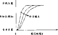
Fig. 3 shows that the displacement of targets of outlet valve is with respect to a plurality of patterns of the variation of elapsed time when exhaust valve opening, and wherein each pattern is corresponding to the external force of each different value;
Fig. 4 is that supply current is with respect to a plurality of patterns of the variation of elapsed time before showing, wherein each pattern is corresponding to the external force of each different value;
Fig. 5 is graphical illustration when working as exhaust valve closure, the displacement of targets of the outlet valve of Fig. 1 and actual displacement, feedback current, preceding supply current and command current sequential chart over time;
Fig. 6 shows that the displacement of targets of outlet valve is with respect to a plurality of patterns of the variation of elapsed time when exhaust valve closure, and wherein each pattern is corresponding to the external force of each different value;
Fig. 7 is the flow chart of a part of control routine of driving of the outlet valve of graphical illustration control graph 1;
Fig. 8 is the flow chart of another part control routine of driving of the outlet valve of graphical illustration control graph 1; And
Fig. 9 is the mapping that relates to when determining feedback gain.
Concrete Implementation Modes
Below will describe in detail and use the present invention, the most preferred embodiment of the driving-controlling device of the suction valve of controlling combustion engine and the driving of outlet valve.
In the present embodiment, all suction valves and outlet valve are configured to the Electromagnetic Drive valve with the electromagnetic force opening and closing that apply electromagnet thereon.Suction valve is structurally identical substantially with outlet valve, and controls with identical substantially pattern when they drive.Therefore hereinafter, the structure and the operation of outlet valve will be described in detail.
With reference to figure 1, outlet valve 10 comprises valve shaft 20, be configured in valve shaft 20 one of axial relative two ends valve body 16 and be used in the Electromagnetic Drive part 21 that axially drives valve shaft 20 in the other direction.Valve shaft 20 supports like this, makes that by cylinder head 18 axle 20 can pass through 21 to-and-fro motion of Electromagnetic Drive part.Cylinder head 18 has the relief opening 14 that is communicated with the firing chamber 12 of motor.Valve seat 15 forms near the opening of relief openings 14.Along with valve shaft 20 to-and-fro motion, valve body 16 lean against or near valve seat 15 so that close relief opening 14, and lift off a seat 15 so that open relief opening 14.
Following stopper 22 is configured in the end away from valve body 16 of valve shaft 20.Lower spring 24 is arranged on down between stopper 22 and the cylinder head 18, be in compressive state.Elastic force by lower spring 24 promotes valve body 16 and valve shaft 20 in valve closes direction (being that Fig. 1 makes progress).
In the shell (not shown) of Electromagnetic Drive part 21, upper iron core 32 is fixed between stopper 30 and the armature 28, and unshakable in one's determination 34 is fixed between armature 28 and the following stopper 22 down.Upper iron core 32 and following unshakable in one's determination 34 is made of high-permeability material, takes circular shape.Armature shaft 26 runs through the central part of each annular core 32,34 like this, feasible axle 26 can be with respect to 32,34 to-and-fro motion unshakable in one's determination.
Its circular groove 40 that is centered close on the axle of armature shaft 26 is formed at the bottom surface towards armature 28 of upper iron core 32.Last coil 42 is installed in the circular groove 40.Last coil 42 and upper iron core 32 constitute electromagnet 61, are used for driving outlet valve 10 to the valve closes direction.
Its circular groove 44 that is centered close on the axle of armature shaft 26 is formed at down iron core 34 the end face towards armature 28.Lower coil 46 is installed in the circular groove 44. Lower coil 46 and 34 formation electromagnets 62 unshakable in one's determination down are used for driving outlet valve 10 to the valve opening direction.
In the operation, under the control of the electronic controller 50 of the various control operations of handling internal-combustion engine, electric current puts on the coil 42,46 of electromagnet 61,62.Electronic controller 50 comprises CPU, storage and is used to supply the exciting circuit of exciting current to the coil 42,46 of electromagnet 61,62.Electronic controller 50 also comprises: the input circlult (not shown) is used to receive detected signal and other signals from displacement transducer 52; The A/D converter (not shown) becomes detected signal suitable digital signal or the like as analog signal conversion.
Fig. 1 shows the following state of outlet valve 10: upwards coil 42 and lower coil 46 do not provide exciting current, so electromagnet 61,62 does not produce electromagnetic force.Under this state, armature 28 is by any one electromagnetic attracting force in the electromagnet 61,62, but is still in the neutral position between unshakable in one's determination 32,34, in this position, and the mutual balance of elastic force of spring 24,38.Keep at outlet valve 10 under the situation of state of Fig. 1, valve body 16 separates, makes relief opening 14 to be in semi-open state with valve seat 15.Hereinafter the position of the outlet valve in the state of Fig. 1 10 is called " neutral position ".
The operation of the outlet valve 10 that the control of the electric current by putting on coil 42,46 drives below will be described.
Before beginning to drive outlet valve 10 on the opening and closing direction, implement a process (being called " initial driving process ") so as with outlet valve 10 from middle position transfer or move to full close position corresponding to an end of the stroke of valve shaft 20, and keep outlet valve 10 static or be stabilized in this position.In the initial driving process, alternately be applied on the coil 42,46 with predetermined time interval from the exciting current of the exciting circuit of electronic controller 50.Put under the situation of the electric current of coil 42,46 armature 28, armature shaft 26, valve shaft 20 or the like forced vibration under the influence of the electromagnetic force that the elastic force and the electromagnet 61,62 of spring 24,38 alternately produces in such control.Thereby the amplitude of armature 28 vibrations little by little increases, and becomes and upper iron core 32 adjacency up to armature 28.When armature 28 during against upper iron core 32, electric current stops to put on lower coil 46, and continuously upwards coil 42 supply with constant exciting current.As a result, armature 28 attracted to upper iron core 32 by the electromagnetic force that is produced by electromagnet 61, and maintains this state, and in this case, armature 28 leans against on the upper iron core 32.Thereby outlet valve 10 keeps full close position, and promptly the initial operation state makes that valve 10 follow-up opening and closing actions are carried out.
For with the operation of internal-combustion engine synchronously opening and closing be placed in the outlet valve 10 of full close position at first, the exciting current of being made up of feedforward current component (hereinafter to be referred as " FF electric current I f ") and feedback current component (hereinafter to be referred as " FB current Ib ") (hereinafter to be referred as " command current I ") is fed to the coil 42,46 of electromagnet 61,62 selectively from the exciting circuit of electronic controller 50.
The driving force that is used for opening and closing outlet valve 10 is determined by quality of the elastic force of spring 24,38, valve body 16, valve shaft 20, armature 28, armature shaft 26 or the like basically.Driving force also changes with the value at the surface friction drag of each sliding parts, for example, and the junction point between armature shaft 26 and unshakable in one's determination 32,34 and the sassafras resistance that rubs of the junction point between valve shaft 20 and the cylinder head 18.In addition, because valve body 16 bears the external force based on firing chamber 12 and relief opening 14 internal pressures, under the influence of external force, change so act on the driving force of outlet valve 10.
Sufficiently high operational stability in order to ensure outlet valve 10, the value of the electromagnetic force that is produced by electromagnet 61,62 must be set, in other words, the exciting current that offers coil 42,46 is set to suitable value, makes the surface friction drag of the sliding parts that the driving force reflection that produced is different and the external force that caused by firing chamber 12 pressure inside or the like.
Though that the value of the surface friction drag of each sliding parts is considered to is constant substantially, irrelevant with engine load,, the value of the external force that is caused by the pressure in the firing chamber 12 etc. may greatly change according to engine load.For example, owing to the increase of firing pressure with engine load increases, therefore firing chamber 12 pressure inside when outlet valve 10 is opened and the exhaust pressure of relief opening 14 also increase, and cause the increase by the external force of above-mentioned pressure generation.Therefore, if do not consider external force when determining to put on the exciting current of coil 42,46, the electromagnetic force that is used to drive outlet valve 10 may become not enough, causes the reduction of the operational stability of outlet valve 10.In other cases, outlet valve 10 may be driven by excessive electromagnetic force, cause power consumption to increase and/or the vibration when outlet valve 10 opening and closing and noise (for example, comprising the noise that produces between the contact of armature 28 and iron core 32,34 and the collision between valve seat 15 and the valve body 16).
Therefore, according to embodiments of the invention, FF electric current I f and FB current Ib suitably are set so that external force and the surface friction drag that reflection is produced by the pressure of firing chamber 12 etc., make outlet valve 10 with sufficiently high stability operation, and can not run into the problems referred to above, increase and noise and vibration when occurring in opening and closing as power consumption.
The control operation of the driving when below with reference to the sequential chart of Fig. 2 outlet valve 10 being opened is described, and the control operation of the driving will close it with reference to the sequential chart of figure 5 time is described.
Among Fig. 2, (a) the displacement of targets Xt of expression outlet valve 10 when outlet valve 10 is opened and actual displacement X over time, (b), (c) and (d) represent FB current Ib, FF electric current I f and command current I over time.
As shown in Figure 2, between time t0 and t1, the value of FF electric current I f is arranged to If2 (maintenance electric current), is made armature 29 keep attracteding to upper iron core 32 and keeping this initial position.During this period, the FB current Ib is arranged to zero.Thereby the command current that offers coil 42 equals to keep electric current I f2, and outlet valve 10 remains on full close position.
For initial position is thus opened outlet valve 10, FF electric current I f make to stop upwards coil 42 provision commands electric current I, and outlet valve 10 discharges from full close position at first at time t1 set to zero.Because command current I just equals zero after full close position discharges at outlet valve 10, so the moveable part of outlet valve shifts or moves to fully open position under the bias force of upper spring 38.Between time t1 and t2, when the air gap G between armature 28 and following unshakable in one's determination 34 reached predetermined value G1, FF electric current I f and FB current Ib all kept equalling zero.
Calculate the FB current Ib, make outlet valve equal corresponding displacement of targets Xt constantly at each actual displacement X constantly.Thereby FB current Ib and FF electric current I f consider external force and are provided with.
More precisely, FF electric current I f calculates according to external force of estimating and elapsed time T, thereby a current value is set, this current value makes actual displacement X follow the pattern of the displacement of targets Xt that selects according to external force.The FF electric current I f that Fig. 4 shows calculating like this is a plurality of patterns of the variation of (elapsed time T) in time, and each pattern is corresponding to the external force value of each different estimation.Can find out obviously that from Fig. 4 the moment that the FF electric current becomes greater than zero increases and shifts to an earlier date along with external force, and the value of FF electric current increases with the increase of external force.
At moment t2 (in Fig. 2) and thereafter, air gap G becomes and equals predetermined value G1, and the deviation delta X that departs from the displacement of targets Xt that changes with external force according to actual displacement X calculates the FB current Ib.That is, determine the FB current Ib so that reduce or eliminate offset deviation Δ X.Greater than zero moment t2 with in the period between the t3, bid value I is arranged to equal the FB current Ib at FF electric current I f, only carries out feedback control according to the FB current Ib so that control puts on the electric current of lower coil 46.
In case elapsed time T reaches FF electric current I f greater than zero moment t3, FF electric current I f is arranged to the value (greater than zero) that the external force with elapsed time T and estimation becomes.Thereby, calculation command value I, as FF electric current I f and FB current Ib and, and, except that above-mentioned feedback control, carry out feedforward control so that control the electric current that puts on lower coil 46 according to FF electric current I f.
When outlet valve 10 when in fact t4 constantly reaches fully open position, offset deviation Δ X equals zero, and the FB current Ib is arranged to zero.Simultaneously, FE electric current I f is arranged to above-mentioned maintenance electric current I f2, thereby outlet valve 10 keeps fully open position.
The control operation of the driving of outlet valve 10 when outlet valve 10 is closed is described below with reference to the sequential chart of Fig. 5.Among Fig. 5, (a) expression when outlet valve 10 is closed the displacement of targets Xt of outlet valve 10 and actual displacement X over time, (b), (c) and (d) represent FB current Ib, FF electric current I f and command current I over time.
As shown in Figure 5, in the period between moment t5 and t6, the value of FF electric current I f is arranged to keep electric current I f2, and the FB current Ib is arranged to zero.Thereby make the command current that offers lower coil 46 equal to keep electric current I f2, thereby outlet valve 10 remain on fully open position.
For initial position is thus closed outlet valve 10, FF electric current I f is set to zero at time t6 at first, make to stop to lower coil 46 provision commands electric current I, thereby outlet valve 10 discharges from fully open position.Because command current I just equals zero after fully open position discharges at outlet valve 10, so the moveable part of outlet valve shifts or moves to full close position under the bias force of lower spring 24.Reach at the air gap G between armature 28 and the upper iron core 32 between the moment t6 and t7 of predetermined value G1, FF electric current I f and FB current Ib all keep equalling zero.
Then, calculate FF electric current I f and FB current Ib so that the actual displacement X of outlet valve 10 (shown in the solid line of Fig. 5) equals corresponding displacement of targets Xt constantly constantly at each.Like this, FB current Ib and FF electric current I f consider external force and are provided with.
More precisely, calculate FF electric current I f, thereby such current value is set, it makes actual displacement X follow the pattern of the displacement of targets Xt that selects according to external force according to the external force and the elapsed time T that estimate.The FF electric current I f of the calculating like this that Fig. 4 shows a plurality of patterns of the variation of the value of (elapsed time T) and different estimation external force in time also is applicable to the situation that outlet valve 10 is closed.
Equal the moment t7 (among Fig. 5) of predetermined value G1 and thereafter at air gap G, the deviation delta X that departs from the displacement of targets Xt that changes with external force according to actual displacement X calculates the FB current Ib.That is, determine the FB current Ib like this so that reduce or eliminate offset deviation Δ X.In period between moment t7 and t8, FF electric current I f is greater than zero, and bid value I equals the FB current Ib, only carries out feedback control so that control puts on the electric current of coil 42 according to the FB current Ib.
In case elapsed time T reaches FF electric current I f greater than zero moment t8, FF electric current I f is configured to the value (greater than zero) that the external force with elapsed time T and estimation becomes.Thereby, calculation command value I, as FF electric current I f and FB current Ib and, except that above-mentioned FB feedback control, carry out feedforward control so that control the electric current that puts on coil 42 according to FF electric current I f.
When outlet valve 10 when in fact t9 constantly reaches full close position, offset deviation Δ X equals zero, and the FB current Ib is configured to zero.Simultaneously, FE electric current I f is configured to above-mentioned maintenance electric current I f2, thereby outlet valve 10 keeps full close position.
Control flow below with reference to the driving of Fig. 7 and Fig. 8 figure description control outlet valve 10.Control routine shown in the flow chart is by electronic controller 50 section execution repeatedly at a time.
At first, determine at the step S101 of Fig. 7 whether outlet valve 10 just discharges from full cut-off or fully open position.If obtain sure judgement (being) at step S101, the timer that then will be used to measure from outlet valve 10 releases constantly beginning elapsed time T resets at step S102.At step S103, determine whether elapsed time T equals above-mentioned period Δ t.If obtain sure judgement (being) at step S103, then execution in step S104 is so that equal the value that actual displacement X that Δ t measures constantly estimates to act on the external force that stops outlet valve 10 motions according to outlet valve 10 at elapsed time T.
At the step S105 of Fig. 8, determine that whether elapsed time T is greater than period Δ t.If obtain sure judgement (being), then according to estimating that external force and elapsed time T calculate FF electric current I f at step S106 at step S105.Fig. 4 has obviously shown the variation of FF electric current I f according to external force and elapsed time T, and FF electric current I f increases with external force, so that be arranged to be suitable for compensating the value of external force influence.
When in the judgement (deny) that above-mentioned steps S105 to negate, that is, and when definite elapsed time T equals or during deficiency period Δ t, FF electric current I f is arranged to zero.
At next step S108, determine whether the air gap G between armature 29 and each electromagnet 61,62 is equal to or less than predetermined value G1.Air gap G is defined as armature 28 and current armature 28 towards its upper iron core that moves 32 and one distance in unshakable in one's determination 34 down.That is, when outlet valve 10 was opened, air gap G represented the distance between armature 28 and following unshakable in one's determination 34, and when outlet valve 10 was closed, air gap G represented the distance between armature 28 and the upper iron core 32.
Carry out above-mentioned steps S108, so that determine whether to begin feedback control based on the FB current Ib according to the size of air gap G.Because the moment that following reason, feedback control begin is determined according to the value of air gap G.
Suppose that the level of identical exciting current offers electromagnet 61 or 62 substantially, the electromagnetic force that acts on armature 28 reduces with the increase of air gap G.In other words, along with air gap G increases, the increase part that offers the electric energy of electromagnet 61 or 62 may be wasted, and does not promote the attraction of armature 28 towards the direction of the iron core of correspondence.Therefore, in above-mentioned control routine, has only the feedback control of when determining that air gap G is equal to or less than predetermined value G1, just carrying out based on according to the FB electric current of offset deviation Δ X.If air gap G is greater than predetermined value G1, mean by electromagnet 61 or 62 armatures 28 that drive and attracted to corresponding iron core 32 or 34 with low electrical efficiency, be set to zero by the FB current Ib, stop feedback control substantially, so that the increment of power consumption is minimized.
If obtain sure judgement (being), calculate FF electric current I f at step S109 according to external force of estimating and elapsed time T at step S108., when outlet valve 10 was opened, so the displacement of targets that calculates changed with external force and elapsed time T as shown in Figure 3, and when outlet valve 10 was closed, so the displacement of targets that calculates changed with external force and elapsed time T as shown in Figure 6.
Subsequently, at step S110 according to following formula (1) displacement calculating deviation delta X:
ΔX=Xt-X (1)
Then at step S111 based on offset deviation Δ X, calculate the FB current Ib according to following formula (2):
Ib=KΔX (2)
In the above-mentioned representation, " K " is feedback gain, and is arranged to steady state value in this embodiment.
Here, calculate the displacement of targets Xt that is used to displacement calculating deviation delta X, so that along with acting on the increase that outlet valve 10 stops the external force of its motion, outlet valve 10 shifts more slow or moves.Thereby the FB current Ib is arranged to be suitable for compensating the current value of external force influence.
On the other hand, if obtain negative judgement (denying) in above-mentioned steps S108, then the FB current Ib is arranged to zero in step S112.
After step S111 or step S112 determine the FB current Ib, calculate according to following formula (3) at step S113 and will be added to one the last command current of selecting in the electromagnet 61,62 " I ":
I=Ib+If (3)
At step S114, so the command current I that determines is added to one that selects in the electromagnet 61,62.More precisely, when outlet valve 10 was opened, command current I was provided for lower coil 46, and when outlet valve 10 was closed, command current I was provided for coil 42.With such pattern, the electric current that puts on corresponding electromagnet 61,62 by control is controlled the value of the electromagnetic force that each electromagnet 61,62 produces.The control routine of Fig. 7 and Fig. 8 stops after execution in step S114.
Though described the structure of outlet valve 10 in detail and to the control mode of the driving of this valve 10,, can as outlet valve 10, construct suction valve, and with the driving of same substantially pattern control suction valve.
The embodiment of graphical illustration produces following advantage.
(1) the displacement of targets Xt of engine valve such as suction valve or outlet valve 10 is according to the patterns of change of selecting, make engine valve slower or mildly move or shift along with the increase of the external force that stops valve motion.X calculates the FB current Ib according to the offset deviation Δ, makes the actual displacement X of engine valve meet displacement of targets Xt, and so adjusts to optimum value so that the influence of compensation external force.By according to the command current I that calculates by FB electric current or the like, control the electric current that puts on electromagnet 61 or 62, drive engine valve with the suitable electromagnetic force value consistent with external force.This configuration can be avoided this situation: owing to causing engine valve to drive with low operational stability with respect to the hypodynamic electromagnetic force of required usefulness that drives engine valve.Above-mentioned configuration can avoid engine valve to drive with excessive electromagnetic force simultaneously, and that may cause the increase of power consumption and/or noise and vibration take place when the opening and closing valve.
(2) putting on electromagnet 61,62, be used under the control of electric current of opening and closing engine valve, FF electric current I f is arranged to make the actual displacement X of engine valve to equal the current value of displacement of targets Xt according to external force and elapsed time T.Then, according to the control of carrying out by the command current of FF electric current I f and feedback current Ib calculating the electric current that puts on electromagnet 61,62.Thereby, put on control that electromagnet 61,62 is used for the electric current of opening and closing engine valve and comprise feedforward control according to FF electric current I f, therefore can carry out the control of the not free electric current that postpones.
(3) the actual displacement X that begins the engine valve measured behind the transit time Δ t according to the moment of being arranged to zero (moment t1 of Fig. 2 and the moment t6 of Fig. 5) from the command current I that will once keep equaling keeping electric current I f2 estimates to act on the external force of engine valve.Time Δ t is arranged in and makes the period that once keeps null command current I to stop before greater than moment (t3) of zero, that is, air gap G become feedback control greater than predetermined value G1 based on the FB current Ib begin before period of termination.Thereby, in the moment of transit time Δ t, before the electromagnet that once is placed in de-energized state (after maintenance electric current I f2 is provided) encourages once more with the FB current Ib, according to the actual displacement X estimation external force of engine valve.The actual displacement X of the engine valve of time measurement at this moment is not subjected to the influence by the electromagnetic force of electromagnet generation, therefore gets suitable value so that accurately consider to act on the external force of engine valve.Therefore, can suitably estimate external force, and not need to be used to estimate to act on the new sensor of the external force of engine valve according to actual displacement X.
Can the embodiments of the invention of graphical illustration be modified as follows.
Be used for to change for example reference mapping as shown in Figure 9 along with the size of air gap G and the value of offset deviation Δ X according to the feedback gain " K " of offset deviation Δ X calculating FB electric current Tb.In this case, feedback gain " K " is arranged to predetermined value K0, k1, k2 and the k3 corresponding to separately regional A, B, C and the D of Fig. 9, determines or definition according to air gap G and offset deviation Δ X.To k5, set up the relation of following formula (4) expression about predetermined value k1 in advance.
K0<K1<K2<K3 ... (4) wherein K0 equals zero.
When offset deviation Δ X was minimum, the feedback gain " K " that can be arranged to aforesaid variable was configured to zero, and when offset deviation Δ X during greater than a certain value step by step along with air gap G increase and increase.Because when applying a certain command current I to the electromagnet of selecting, the electromagnetic force that acts on engine valve increases along with air gap G and descends, so feedback gain " K " increases with the increase of air gap G.Suppose that identical exciting current I offers this electromagnet, the electromagnetic force that then acts on engine valve descends with the increase of air gap.Along with the increase of above-mentioned air gap G, be set to bigger value by feedback gain K, thereby can produce the electromagnetic force of the value that is suitable for air gap G size at the electromagnet of selecting.Thereby the actual displacement X of engine valve can be adjusted to displacement of targets Xt in the short relatively time, follows the pattern that displacement of targets Xt selects with highi degree of accuracy and reliability simultaneously.With the aforesaid feedback gain K that becomes variable, only the command current I of the necessity that will be provided with according to air gap G offers the electromagnet of selection, thereby on displacement transducer 52, reduce or suppress adverse influences such as noise, promptly may be by the caused influence of excessive electric current of the electromagnet that offers selection.
Can feedback gain " K " be set to variable according to needed mode.For example, feedback gain " K " can determine to make feedback gain " K " step by step along with air gap G increases according to air gap G individually.Perhaps, feedback gain K can change continuously according to air gap G, represents relationship expression between air gap and the feedback gain (5) below utilizing, and does not use mapping etc.
K=KaG+Kb (5)
G: air gap
Ka, Kb: constant
In the embodiment of graphical illustration, the command current I that uses when not putting the electric current that control puts on each electromagnet 61,62 according to FB current Ib and FF electric current I f is so that carry out feedback control and feedforward control simultaneously.But, can only carry out feedback control, for example, by only controlling the electric current that puts on each electromagnet 61,62 according to the FB current Ib.
In the embodiment of graphical illustration,, calculate the FB current Ib according to offset deviation Δ X by only calculating the P item (proportional) of PID control (proportional-integral-differential control).But except that P item (proportional), also can calculate I item (integral) and D item (differential term).
In the embodiment of graphical illustration, the actual displacement X that begins the engine valve measured behind the transit time Δ t according to the moment when the command current I that will once keep equaling keeping electric current I f2 is arranged to zero estimates to act on the external force of engine valve.But the present invention is not limited to the pattern of this estimation.For example, can estimate to act on the value of the external force of engine valve according to the pressure of firing chamber 12 and/or relevant suction port or relief opening pressure inside.More particularly, can be provided for detecting the in-cylinder pressure sensor and the suction port pressure transducer that is used to detect the pressure in the suction port of the pressure in the firing chamber 12, and act on the value of the external force of suction valve according to the pressure difference estimation of pressure in the firing chamber 12 and the pressure in the suction port.Equally, can be provided for detecting the in-cylinder pressure sensor and the exhaust port pressure sensor that is used to detect the pressure in the relief opening of the pressure in the firing chamber 12, and act on the value of the external force of outlet valve according to the pressure difference estimation of pressure in the firing chamber 12 and the pressure in the relief opening.
In addition, as mentioned above, the value that acts on the external force of engine valve becomes with the load of motor.The load of motor can be calculated according to the output (or reduction amount of accelerator pedal) of the accelerator position sensor that is used to detect accelerator pedal position and the output that is used for the engine speed sensor of detection of engine speed.The load of motor also can or be used to detect the output of Air flow meter of the amount (or flow rate) of the suction gas that is drawn into internal-combustion engine according to the output of the throttle valve turn on sensor that is used to detect the throttle valve opening angle, replaces the output of accelerator position sensor to calculate.
In addition, the value that acts on the external force of engine valve becomes with the valve sequential that engine valve opens and closes.Thereby the value of the external force of estimating according to the load of motor that acts on engine valve can be revised by modulating valve sequential suitably.
Claims (20)
1. the driving-controlling device of the driving of the engine valve (10) of the electromagnetic force controlling combustion engine that produces by two electromagnets (61,62) of a utilization, it comprises:
Estimation unit is used to estimate put on the value of the external force of described engine valve;
Setting device is used to be provided with the displacement of targets of the described engine valve of the estimated value of considering external force; And
Control gear is used for controlling the electric current that puts on described two electromagnets according to the actual displacement and the described displacement of targets of described engine valve, makes described actual displacement meet the described displacement of targets that described setting device is provided with substantially.
2. the driving-controlling device of claim 1, it is characterized in that: described control gear calculates the feedback current with current value that the deviation with described actual displacement and described displacement of targets becomes, and controls the electric current that puts on described two electromagnets according to the described feedback current that calculates.
3. the driving-controlling device of claim 2, it is characterized in that: described control gear is provided with the feedback gain that uses when calculating described feedback current, makes described feedback gain increase along with the increase of air gap between the electromagnet of selecting in described engine valve and described two electromagnets.
4. claim 2 or 3 driving-controlling device, it is characterized in that: described control gear setting has the preceding supply current of the current value that is added to described feedback current, so that make described actual displacement equal described displacement of targets substantially, and put on the electric current of described two electromagnets according to supply current before described and the control of described feedback current.
5. the driving-controlling device of claim 4 is characterized in that: along with acting on the increase that described engine valve stops the external force of its motion, described before supply current application time in advance, and the current value of supply current increases before described.
6. any one driving-controlling device among the claim 1-3, it is characterized in that: described estimation unit estimates that according to the described actual displacement of described engine valve the value of external force, described actual displacement are to remain on when wherein not having electric current to be added to nonexcited state on the engine valve detected when two electromagnets.
7. the driving-controlling device of claim 6, it is characterized in that: described estimation unit is according to the value of the described actual displacement estimation external force of described engine valve, and described actual displacement is detected in the predetermined periods that described engine valve begins when one of full close position and fully open position discharge.
8. any one driving-controlling device among the claim 1-3, it is characterized in that: at described engine valve during the electromagnet of selecting moves, when the air gap between the electromagnet of selecting in described engine valve and described two electromagnets was equal to or less than predetermined value, described control gear began to apply electric current to described two electromagnets.
9. any one driving-controlling device among the claim 1-3, it is characterized in that: the control of described control gear puts on the electric current of described two electromagnets, make described engine valve from one of full close position and fully open position move to the required time of other positions along with act on described engine valve stop its motion external force increase and increase.
10. any one driving-controlling device among the claim 1-3, it is characterized in that: described setting device stores the time dependent a plurality of displacement of targets patterns of expression displacement of targets, and select one of them pattern according to acting on the external force that described engine valve stops its motion, so that described control gear puts on the electric current of described two electromagnets according to the displacement of targets pattern control of selecting.
11. the method for driving of the engine valve (10) of the electromagnetic force controlling combustion engine that a utilization is produced by two electromagnets (61,62), it may further comprise the steps:
Estimation puts on the value of the external force of described engine valve;
The displacement of targets of described engine valve of the described estimated value of described external force is considered in setting; And
Actual displacement and described displacement of targets according to described engine valve are controlled the electric current that puts on described two electromagnets, make described actual displacement meet described displacement of targets substantially.
12. the method for claim 11 is characterized in that: calculate its current value and depart from the feedback current that the deviation of described displacement of targets becomes, and put on the electric current of described two electromagnets according to the described feedback current control of calculating with described actual displacement.
13. the method for claim 12 is characterized in that: the feedback gain that uses when determine calculating described feedback current makes described feedback gain increase along with the increase of air gap between the electromagnet of selecting in described engine valve and described two electromagnets.
14. the method for claim 12 or 13, it is characterized in that: its current value is set is added to described feedback current, and put on the electric current of described two electromagnets according to supply current before described and the control of described feedback current so that make described actual displacement equal the preceding supply current of described displacement of targets substantially.
15. the method for claim 14 is characterized in that: along with acting on the increase that described engine valve stops the external force of its motion, the application time of described preceding supply current shifts to an earlier date, and the current value of supply current increases before described.
16. any one method among the claim 11-13, it is characterized in that: estimate that according to the described actual displacement of described engine valve the value of external force, described actual displacement are to remain on when wherein not having electric current to be added to nonexcited state on the described engine valve detected when described two electromagnets.
17. the method for claim 16, it is characterized in that: estimate that according to the described actual displacement of described engine valve the value of described external force, described actual displacement are detected in the predetermined periods that described engine valve begins when one of full close position and fully open position discharge.
18. any one method among the claim 11-13, it is characterized in that: at described engine valve during the electromagnet of selecting moves, when the air gap between the electromagnet of selecting in described engine valve and described two electromagnets was equal to or less than predetermined value, beginning applied electric current to described two electromagnets.
19. any one method among the claim 11-13, it is characterized in that: control puts on the electric current of described two electromagnets, make described engine valve from one of full close position and fully open position move to the required time of other positions along with act on described engine valve stop its motion external force increase and increase.
20. any one method among the claim 11-13, it is characterized in that: the time dependent a plurality of displacement of targets patterns of storage representation displacement of targets, and select one of them pattern according to acting on the external force that described engine valve stops its motion, so that put on the described electric current of described two electromagnets according to the displacement of targets pattern control of described selection.
Applications Claiming Priority (2)
| Application Number | Priority Date | Filing Date | Title |
|---|---|---|---|
| JP388740/00 | 2000-12-21 | ||
| JP2000388740A JP4281246B2 (en) | 2000-12-21 | 2000-12-21 | Engine valve drive control device |
Publications (2)
| Publication Number | Publication Date |
|---|---|
| CN1360137A CN1360137A (en) | 2002-07-24 |
| CN1273721C true CN1273721C (en) | 2006-09-06 |
Family
ID=18855428
Family Applications (1)
| Application Number | Title | Priority Date | Filing Date |
|---|---|---|---|
| CNB011437901A Expired - Fee Related CN1273721C (en) | 2000-12-21 | 2001-12-21 | Device and method for drive control of engine valve |
Country Status (5)
| Country | Link |
|---|---|
| US (1) | US6588385B2 (en) |
| EP (2) | EP1217177A3 (en) |
| JP (1) | JP4281246B2 (en) |
| KR (1) | KR100484053B1 (en) |
| CN (1) | CN1273721C (en) |
Families Citing this family (22)
| Publication number | Priority date | Publication date | Assignee | Title |
|---|---|---|---|---|
| JP2002242708A (en) * | 2001-02-14 | 2002-08-28 | Mikuni Corp | Drive of direct-acting valve for internal combustion engine |
| JP3976131B2 (en) * | 2002-06-10 | 2007-09-12 | 株式会社小松製作所 | Valve stroke sensor |
| JP3743396B2 (en) * | 2002-06-10 | 2006-02-08 | トヨタ自動車株式会社 | Control device for electromagnetically driven valve |
| US6698408B2 (en) * | 2002-07-10 | 2004-03-02 | Eaton Corporation | Position control strategy EGR valve actuator |
| DE10261022A1 (en) * | 2002-12-24 | 2004-07-08 | Robert Bosch Gmbh | Method and control device for actuating solenoid valves associated with gas exchange valves |
| US6810841B1 (en) | 2003-08-16 | 2004-11-02 | Ford Global Technologies, Llc | Electronic valve actuator control system and method |
| US6871617B1 (en) * | 2004-01-09 | 2005-03-29 | Ford Global Technologies, Llc | Method of correcting valve timing in engine having electromechanical valve actuation |
| JP2006057715A (en) * | 2004-08-19 | 2006-03-02 | Toyota Motor Corp | Electromagnetic drive valve |
| US7089895B2 (en) * | 2005-01-13 | 2006-08-15 | Motorola, Inc. | Valve operation in an internal combustion engine |
| JP4577171B2 (en) * | 2005-09-22 | 2010-11-10 | トヨタ自動車株式会社 | Sliding mode controller |
| US7516940B2 (en) * | 2006-05-26 | 2009-04-14 | General Electric Company | Electromagnetic actuators |
| US7651069B2 (en) * | 2006-05-26 | 2010-01-26 | General Electric Company | Electromagnetic actuators |
| US8049147B2 (en) | 2008-03-28 | 2011-11-01 | United Technologies Corporation | Engine inlet ice protection system with power control by zone |
| DE102008024086A1 (en) | 2008-05-17 | 2009-11-19 | Daimler Ag | Valve drive device |
| US7673616B2 (en) * | 2008-07-21 | 2010-03-09 | Ford Global Technologies, Llc | Engine control including knock compensation |
| US20100140519A1 (en) * | 2008-12-04 | 2010-06-10 | General Electric Company | Electromagnetic actuators |
| US8150605B2 (en) * | 2009-02-17 | 2012-04-03 | Ford Global Technologies, Llc | Coordination of variable cam timing and variable displacement engine systems |
| US7835848B1 (en) * | 2009-05-01 | 2010-11-16 | Ford Global Technologies, Llc | Coordination of variable cam timing and variable displacement engine systems |
| EP2363622B1 (en) | 2010-02-25 | 2018-04-18 | Honeywell Technologies Sarl | Method for operating a valve having a stepper motor as actuator |
| JP5358621B2 (en) * | 2011-06-20 | 2013-12-04 | 日立オートモティブシステムズ株式会社 | Fuel injection device |
| US8786455B2 (en) * | 2011-06-23 | 2014-07-22 | Ford Motor Company | Tool lubrication delivery monitoring system and method |
| DE102015217955A1 (en) * | 2014-10-21 | 2016-04-21 | Robert Bosch Gmbh | Device for controlling at least one switchable valve |
Family Cites Families (17)
| Publication number | Priority date | Publication date | Assignee | Title |
|---|---|---|---|---|
| US5636601A (en) * | 1994-06-15 | 1997-06-10 | Honda Giken Kogyo Kabushiki Kaisha | Energization control method, and electromagnetic control system in electromagnetic driving device |
| DE19518056B4 (en) * | 1995-05-17 | 2005-04-07 | Fev Motorentechnik Gmbh | Device for controlling the armature movement of an electromagnetic switching device and method for driving |
| JPH09217859A (en) | 1996-02-09 | 1997-08-19 | Toyota Motor Corp | Operation state detecting device for valve device |
| US5647311A (en) * | 1996-11-12 | 1997-07-15 | Ford Global Technologies, Inc. | Electromechanically actuated valve with multiple lifts and soft landing |
| JPH10205314A (en) * | 1996-12-13 | 1998-08-04 | Fev Motorentechnik Gmbh & Co Kg | Method for controlling solenoid valve driving part of gas exchange valve |
| US6208497B1 (en) * | 1997-06-26 | 2001-03-27 | Venture Scientifics, Llc | System and method for servo control of nonlinear electromagnetic actuators |
| DE19733140A1 (en) * | 1997-07-31 | 1999-02-04 | Fev Motorentech Gmbh & Co Kg | Operating method for electromagnetic actuator on piston engine |
| DE19739840C2 (en) * | 1997-09-11 | 2002-11-28 | Daimler Chrysler Ag | Method for controlling an electromagnetically actuated actuating device, in particular a valve for internal combustion engines |
| JP3433788B2 (en) * | 1997-10-24 | 2003-08-04 | トヨタ自動車株式会社 | Control device for electromagnetically driven valve |
| WO1999034378A1 (en) * | 1997-12-23 | 1999-07-08 | Siemens Aktiengesellschaft | Device for controlling an electromechanical regulator |
| JP3695118B2 (en) * | 1998-01-12 | 2005-09-14 | トヨタ自動車株式会社 | Control device for electromagnetically driven valve |
| JP3465568B2 (en) * | 1998-01-19 | 2003-11-10 | トヨタ自動車株式会社 | Electromagnetic drive valve control device for internal combustion engine |
| AU1467600A (en) * | 1998-11-06 | 2000-05-29 | Perry Robert Czimmek | Method of compensation for flux control of an electromechanical actuator |
| DE19852655B4 (en) | 1998-11-16 | 2005-05-19 | Daimlerchrysler Ag | Method for operating an electromagnetic actuator for actuating a gas exchange valve |
| US6158403A (en) * | 1999-03-30 | 2000-12-12 | Aura Systems, Inc. | Servo control system for an electromagnetic valve actuator used in an internal combustion engine |
| JP3487216B2 (en) * | 1999-05-11 | 2004-01-13 | トヨタ自動車株式会社 | Solenoid driven valve |
| JP4281257B2 (en) * | 2000-06-29 | 2009-06-17 | トヨタ自動車株式会社 | Engine valve drive control device |
-
2000
- 2000-12-21 JP JP2000388740A patent/JP4281246B2/en not_active Expired - Fee Related
-
2001
- 2001-12-19 EP EP01130196A patent/EP1217177A3/en not_active Ceased
- 2001-12-19 US US10/020,912 patent/US6588385B2/en not_active Expired - Fee Related
- 2001-12-19 EP EP09157760A patent/EP2108789B1/en not_active Expired - Lifetime
- 2001-12-20 KR KR10-2001-0081638A patent/KR100484053B1/en not_active IP Right Cessation
- 2001-12-21 CN CNB011437901A patent/CN1273721C/en not_active Expired - Fee Related
Also Published As
| Publication number | Publication date |
|---|---|
| JP2002188470A (en) | 2002-07-05 |
| EP1217177A2 (en) | 2002-06-26 |
| EP1217177A3 (en) | 2007-11-28 |
| JP4281246B2 (en) | 2009-06-17 |
| EP2108789B1 (en) | 2012-08-29 |
| CN1360137A (en) | 2002-07-24 |
| KR100484053B1 (en) | 2005-04-18 |
| EP2108789A2 (en) | 2009-10-14 |
| US20020078910A1 (en) | 2002-06-27 |
| EP2108789A3 (en) | 2010-03-31 |
| KR20020050723A (en) | 2002-06-27 |
| US6588385B2 (en) | 2003-07-08 |
Similar Documents
| Publication | Publication Date | Title |
|---|---|---|
| CN1273721C (en) | Device and method for drive control of engine valve | |
| EP1298307B1 (en) | Control device of common rail fuel injection system of an engine | |
| CN1317495C (en) | Air-valve driving system and apparatus thereof for IC engine | |
| JP4281257B2 (en) | Engine valve drive control device | |
| KR100271903B1 (en) | Method of detecting malfunctions of the electronic-driving valve for air intake and exhaust | |
| JP4868554B2 (en) | Injection valve drive method | |
| JP2002266667A (en) | Control device for solenoid drive valve | |
| EP2245286A1 (en) | Control apparatus and control method for variable valve operating mechanism | |
| CN1730917A (en) | Cam phase control system for internal combustion engine | |
| CN1308182A (en) | Volume controlling device and method for displacement compressor | |
| CN1292158C (en) | General engine control system | |
| KR20160010331A (en) | Method for controlling clutch and automatic clutch control device | |
| JP2007023800A (en) | Valve characteristic control device for internal combustion engine | |
| JP2008175165A (en) | Hydraulic actuator control device | |
| CN1710258A (en) | Exhaust valve drive control method and device | |
| JP5614141B2 (en) | Variable valve operating device for internal combustion engine | |
| CN1842660A (en) | Engine lag down suppressing device of construction machinery | |
| US20010002586A1 (en) | Control system for electromagnetic actuator | |
| JP2009092077A (en) | Hydraulic actuator control device | |
| JP2006183603A (en) | Electric actuator control method for variable valve mechanism | |
| JP4089614B2 (en) | Variable feedback gain energization control method for electromagnetically driven valve | |
| US6920848B2 (en) | Driver or direct acting valve for internal combustion engine | |
| JP2004360853A (en) | Hydraulic control device of automatic transmission for vehicle | |
| JP2007085318A (en) | Control device of electromagnetic-drive valve | |
| JP2005016658A (en) | Control device of solenoid actuated valve |
Legal Events
| Date | Code | Title | Description |
|---|---|---|---|
| C06 | Publication | ||
| PB01 | Publication | ||
| C10 | Entry into substantive examination | ||
| SE01 | Entry into force of request for substantive examination | ||
| C14 | Grant of patent or utility model | ||
| GR01 | Patent grant | ||
| C17 | Cessation of patent right | ||
| CF01 | Termination of patent right due to non-payment of annual fee |
Granted publication date: 20060906 Termination date: 20101221 |