CN1272829A - Fire extinguisher - Google Patents
Fire extinguisher Download PDFInfo
- Publication number
- CN1272829A CN1272829A CN98809778.8A CN98809778A CN1272829A CN 1272829 A CN1272829 A CN 1272829A CN 98809778 A CN98809778 A CN 98809778A CN 1272829 A CN1272829 A CN 1272829A
- Authority
- CN
- China
- Prior art keywords
- described device
- container
- plunger
- fire
- guide rail
- Prior art date
- Legal status (The legal status is an assumption and is not a legal conclusion. Google has not performed a legal analysis and makes no representation as to the accuracy of the status listed.)
- Granted
Links
Images


Classifications
-
- A—HUMAN NECESSITIES
- A62—LIFE-SAVING; FIRE-FIGHTING
- A62C—FIRE-FIGHTING
- A62C13/00—Portable extinguishers which are permanently pressurised or pressurised immediately before use
Landscapes
- Health & Medical Sciences (AREA)
- Public Health (AREA)
- Business, Economics & Management (AREA)
- Emergency Management (AREA)
- Fire-Extinguishing By Fire Departments, And Fire-Extinguishing Equipment And Control Thereof (AREA)
- Fire Alarms (AREA)
- Containers And Packaging Bodies Having A Special Means To Remove Contents (AREA)
- Loading And Unloading Of Fuel Tanks Or Ships (AREA)
Abstract
A fire extinguisher including a spraying biased plunger (50) controlled by a trigger mechanism (44) wherein the plunger is mounted in a flame retardant compound container (12) and the spring (42) and plunger cooperate, when the trigger mechanism is activated, to discharge flame retardant compound from the container toward a fire. The extinguisher has a handle end (18) and an outlet end at opposite ends of its length such that a user can hold the outlet end in a remote location away from the user when compound is discharged. The extinguisher can also be mounted and provided with a heat sensor (302) for automatic activation.
Description
The present invention relates generally to fire extinguisher, particularly relate to a kind of simple spring load tubulose fire extinguisher, it both can manually-operatedly be operated, and again the temperature-sensitive fuse link can be installed so that operation automatically.
There are a lot of dissimilar hand-held fire extinguisher systems to can be used for the M/C fire extinguishing.Great majority manually fire extinguisher comprise a kind of dry type or wet type fire extinguishing chemical compound that is under the pressure, this cmpd is contained in the cylindrical oil tank, and this storage tank comprises an opening in its bottom, also comprise a siphon, the one end links to each other with above-mentioned opening, and the other end links to each other with the valve of sealing outlet; A starter gear that is used for switch valve; And a nozzle or the nozzle in hose end, be used for directly cmpd being sprayed to the flame fire extinguishing.
In operation, in order to put out a fire, the user directly points to the nozzle end of flexible pipe the bottom of flame, and triggers starter gear and open valve.This fire extinguisher comprises a flexible pipe, and cmpd passes flexible pipe from nozzle end ejection fire extinguishing.Usually, because cmpd must pass the flexible pipe operation before ejection, the length of flexible pipe is restricted, and makes reduce run up time, makes cmpd pass the required pressure minimum of flexible pipe, and minimum cmpd consumption is in flexible pipe.
Such fire extinguisher is just worked when only the pressure in storage tank remains on higher level.In order to ensure enough pressure, except above-mentioned hardware, most of such fire extinguishers comprise one be installed on the valve pressure gauge so that visually indicate pressure of storage tank.When pressure of storage tank drops to threshold level when following, must be to storage tank filler again before using.
Though such fire extinguisher is quite cheap, their shortcoming is a lot.For example, although these fire extinguishers can put out less fire effectively, be not suitable for putting out big fire usually.In order to put out a fire, these fire extinguishers require the user nearer by fire.Although the user can be near little fire and can not be subjected to hot smoking, the temperature that big fire produces will have burned people's danger, though the people not with fiery actual contact.Because the user must catch the nozzle near fire during putting out a fire, so especially dangerous when fire extinguisher is not furnished with the prolongation flexible pipe that links to each other with nozzle.As mentioned above, even be equipped with flexible pipe, in order to reduce run up time, less required pressure of storage tank and make the cmpd of consumption minimum, most of fire extinguishers are shorter relatively, this means that the user has to when fire extinguishing near fire.
Another problem that the fire extinguisher of these types exists is that required element is very expensive.For example, pressure gauge is just very expensive.Another relatively costly element is a storage tank, storage tank must can be under very high pressure the long preservation cmpd.Under normal operation, except satisfying the pressure requirement, storage tank also must satisfy the requirement that the pressure based on ambient temperature changes, and this ambient temperature can change between below zero to 100.And because the chemical compound of a lot of fire extinguishers has corrosive property, the material that this storage tank must not degenerate by contacting with corrosive chemical is made.These all restrictions all require ad hoc to make storage tank, and it is quite expensive to make storage tank specially.
When requiring the shape of special storage tank, the work that a kind of suitable storage tank is provided is with relevant cost even more be a problem.For example, space constraint may limit the degree of depth of storage tank, even a space can hold bigger width.In this case, having the storage tank of an ellipse or rectangular cross section may be the most favourable.But it's a pity that although this shape is possible, their cost is very high usually.
In addition, having to bear high-voltage storage tank will be very heavy.Usually use and under pressure, keep the heavy metal of its shape to form storage tank.For example, for the storage tank that provides under pressure, can bear 10 pounds fire extinguisher material for a long time, the fire extinguisher hardware 15-20 pound that weighs usually, total storage tank that the is full of 25-30 pound that weighs.
Another relevant problem is to be difficult to the heavy fire extinguisher of operation.For example, place that big fire takes place or fire occur in eminence (such as liftoff 6 feet or more than) time, the user must be lifted to the head that is higher than the user to fire extinguisher, so that a fire extinguishing cmpd is sprayed on the fire.Make cmpd on the direction of needs, discharge owing to must control the position of fire extinguisher, more increased the weight of to promote the task of heavy fire extinguisher.
In addition, owing to must keep these fire extinguishers upright for correctly operating, the task of fire extinguisher being pointed to fire is difficult more.When upright, the fire extinguishing cmpd is positioned at above the storage tank opening, and high pressure generates gas, and the position is thereon as mentioned above.When opening valve, this gas makes cmpd ejection opening.
It's a pity that when storage tank was not upright, cmpd wherein moved, and will enter the nethermost possible position of tank inside under the effect of gravity.For example, if reversing, this storage tank make opening be in the top of storage tank.This cmpd will be relative with opening.In this case, when valve was opened, gas rather than cmpd were discharged, and fire extinguisher is invalid.When fire extinguisher is vertically placed, also be this situation.
In order to overcome the weight limits relevant with these fire extinguishers, these fire extinguisher pressure inside and designs of nozzles should make cmpd penetrate with high speed, make cmpd at a good pace to advance several feet.It's a pity that the high-pressure trend compound may often cause " prevailing " and spread." prevailing " is a buzzword of herein using, and is meant when the combustible material situation that fire can spread out from its initial position during from the outburst of its position to take place.For example, spray fire extinguisher when putting out the big fire of grease class when making, the impulsive force of the cmpd of the ejection grease that may cause burning is splashed to all adjacent domains at a high speed, rather than puts out big fire, can make fire spreading arrive adjacent domain.
Another problem of these fire extinguishers is need carry out regular servicing so that still can use.Bottom line must check the pressure meter once every some months, is in more than the threshold level of requirement to guarantee pressure of storage tank.If pressure is not enough, must carry out filler again before use.
Having to these fire extinguishers is their et out of orders under zero gravity with another problem that correctly operation is relevant uprightly.For example, do not have at the outer space under the situation of gravity, even be positioned at stand up position, make the storage tank opening be in the bottom, but because there is not gravity on cmpd, cmpd is easy to float in storage tank, cmpd in the storage tank and gas mix, when opening valve, compound ejection, rather than the ejection of pure cmpd.
Except the hand-held fire extinguisher, but also has the fixed extinguishing system of a lot of dissimilar self-extinguishings.For example, a kind of shower head system is arranged, when detecting heat or cigarette, can be transported to water in the building in one or more zones, by plumbing system to put out the fire that senses.Although these systems are very effective, the system that they are normally the most expensive is because require the plumbing system hardware distribution within a large range, especially in big building.
The exercise question that licenses to the inventor in December 25 nineteen ninety is for having described another example of fixed fire extinguisher in the US Patent 4,979,572 of " extinguishing equipment ".This system design compactness, wherein the fire extinguisher storage tank is fixed in the bonnet by two bolt supports, and its exit end links to each other with baroque pipeline, also comprises cable and one or more temperature-sensitive fuse link.This fuse link is positioned at stove top, makes on the stove and near the fire the stove will melt a fuse link at least.When fuse link melted, cable and trigger mechanism matched and open the exit end of storage tank.When opening storage tank, thing wherein (cmpd of promptly putting out a fire) sprays to stove downwards to put out fire by opening and pipeline configuration.
Stove fixed type system this and other type is extremely important near the fire that great majority occur on the stove and it.By promptly putting out the fire of stove, most of fire damages can drop to minimum, also can avoid a lot of casualties relevant with fire.
The system of the furnace roof fire extinguisher of prior art has lot of advantages, comprises the outward appearance that size is less, more not eye-catching, and be easy to install etc.But in use, there are a lot of shortcomings in this system.
The first, when requiring element littler and still less the time than prior art, this system is still complicated, thereby manufactures very expensive.For example, at least two interconnected pipes of this system requirements are used to spray extinguish material; Several cut cables that are positioned at tube exterior and link to each other by fuse link; And connected system that storage tank is connected to the complexity of pipe.In addition, gas requires a lot of different mechanical element that stand to puncture with power cut mechanism.
The second, this system still is difficult to install.When installing, storage tank is positioned at the top and the rear portion of bonnet.For this system is installed, support has to be fixed on the Background Region of lower surface in the bonnet.Enough help deeply installing under the approaching situation at bonnet, be difficult to arrive the Background Region of bonnet.In addition, because storage tank must become specific angle with respect to plumbing system, must adjust support, and adjust by test and error when mounted.
The 3rd, in case install, this system may not have the outward appearance of requirement.For example, when the inside of bonnet is enough not dark, the pipeline and the construction of cable may be easy to see in the front portion of bonnet, in addition, also storage tank can be seen.But can not arrive under the situation of containment bracket and storage tank especially true deeply at bonnet.
The 4th, this system has the certain operations restriction.For example, fuse link and cut cable are not protected usually, and ejection storage tank material by accident can rupture.
The 5th, after the fuse link fracture, must change whole cable and fuse link assembly, so that reset trigger mechanism.
The 6th, the part trigger mechanism is positioned at the outside of screened housing (being pipeline or other outer rigid housing).In this case, if this system is installed in the less zone, mobile trigger mechanism can partly be placed near bonnet, and this bonnet part may hinder trigger action, so make system invalid when fuse link ruptures.
The 7th, these systems have a lot of shortcomings relevant with above-mentioned hand-held fire extinguisher.For example, it is very expensive to be used for the high pressure storage tank and the pressure gauge of these systems.In addition, storage tank is very heavy usually, and like this, it is very expensive that hardware is installed, and has to maintain these systems.
Therefore, preferably make the hand-held fire extinguisher in light weight, manufacturing cost is lower, and size is little, is applicable to put out big fire and little fire.In addition, preferably make fixed type and automatic system weight also light, cheap, miniaturization, and overcome other restriction relevant with above-mentioned fixed type system.
The present invention includes a fire extinguisher, it comprises a storage tank with first end and second end, and outlet is positioned at second end; A plunger that is installed in the storage tank is used for moving to second end from first end; A bias box that is generally form of springs is used for plunger is pressed to second end; And a trigger mechanism, it makes plunger and bias box be in the state of carrying at first end, starts up to trigger mechanism.When trigger mechanism started, this bias box trailed and makes plunger press to second end, and the cmpd in the storage tank is put out a fire from the outlet ejection.
So, an object of the present invention is to provide a kind of fire extinguisher, wherein during preservation pressure of storage tank is zero.Under this situation, mechanism bears because all spring pressures are triggered, and in fact, pressure of storage tank does not exist.
Another purpose provides a kind of fire extinguisher, and it can spray comprising on vertical, reverse, vertical or the like any direction, and is not subjected to gravity effect.For this reason, because plunger passes through spring rather than high pressure gas promote, the always close outlet of fire extinguishing cmpd, and do not mix with gas.Therefore, when opening valve, the ejection cmpd.
Another purpose of the present invention provides a kind of fire extinguisher, and it can use under high temperature environment.Use fire extinguisher of the present invention, because during preservation in fact cmpd is under the zero pressure, can successfully operation under the temperature that is as low as zero between following 65 to 210.
Best, this storage tank is made by rigid plastic.Another purpose provides a kind of lighter fire extinguisher relatively.For this reason, because storage tank need not remain under the high pressure for a long time, storage tank can be made with other light material of plastics or some, has reduced the total weight of fire extinguisher thus.
And best, container is a partially transparent.Another purpose is a working pressure meter not, reduces the fire extinguisher cost thus.For this reason, because fire extinguisher operation not relevant with pressure of storage tank (that is, only being the function of spring position) does not need pressure gauge.Detect fire extinguisher visibly to confirm full state for making, perhaps storage tank can be made by opaque plastics, and perhaps a part of storage tank is opaque, makes the user as seen to determine whether storage tank is full of, part is full of or has sprayed fully cmpd thus.
Best, fire extinguisher comprises a container, and this container forms a usable material chamber, and it has first and second ends, and forms an outlet at least at second end; The plunger that in this container, can between first and second ends, move; A pusher is used for optionally by usable material chamber from first end to the second end mobile plunger; And a sealing arrangement that is used to export, can operate the sealing device and make extinguish material through outlet.
In one aspect, this pusher comprises a bias box, be used for plunger is pressed to second end, and binary pair that links to each other with plunger, it can move between trigger position and non-trigger position at least, and at non-trigger position, binary pair remains in the usable material chamber plunger, at trigger position, binary pair makes bias box shift to second end to plunger.Best, this bias box is a spring.
In one embodiment, this binary pair comprises an elongated joggle piece, it operationally links to each other with in the spring at least one with plunger, this joggle piece has a plurality of openings, but this binary pair also comprises a shift-in opening or the ratchet that shifts out from opening, optionally meshing joggle piece, and prevent the motion of spring and plunger.
So another purpose provides a kind of cmpd fire extinguisher that part sprays from storage container that helps putting out a fire.This can realize by ratchet and ratchet.
In yet another aspect, this fire extinguisher comprises a handle that is fixed on the container, and this handle forms handle chamber, joggle piece and spring to small part is arranged in handle chamber, ratchet extends by handle, so as by user's finger manipulation from the engagement of joggle piece shift out ratchet, discharge plunger.Best, this ratchet is pressed with joggle piece and meshes.
Aspect another, joggle piece to small part is wound in the handle chamber.
On the other hand, this fire extinguisher comprises a nozzle insert, and cmpd is nebulized when spraying from container.The fire extinguisher that another purpose provides a kind of " soft contact ", when it started, fire extinguisher nebulized the fire extinguishing of ejection cmpd and can not make fiery sending out.This nozzle insert can achieve this end.
On the other hand, this fire extinguisher comprises and is used for container is installed in the device above the monitored zone, but this equipment also comprises the heat sensitive sensor of a sense ambient temperature, when ambient temperature exceeds maxim, makes binary pair to trigger position.
Aspect another, this fire extinguisher is installed near the guarded region, and comprise an independent guide rail with certain-length and an inwall, this inwall forms the guide rail chamber with first and second ends, second end forms an opening, the guide rail chamber of this opening and formation is used for receiving vessel, after container is positioned in the guide rail chamber, second end of this container is in abutting connection with second end of guide rail chamber, an end plug is housed in second end of guide rail chamber, this end plug forms has the plug channels of first and second ends, and first end of formation is used for the opening of airtight container, and second end is used in reference to guarded region.
Best, this guide rail also forms a fire extinguishing agent guide channel that is in the guide wall, and at least one guide rail outlet, and guarded region is pointed in this guide rail outlet, and second end opening of plug channels is in the fire extinguishing agent guide channel.
Best, this guide channel is formed on the inside face of guide rail inwall, and the outer wall of this guide channel and container forms the fire extinguishing agent guide channel together.
Therefore, another object of the present invention provides a kind of fire extinguisher that simply is used for fixing formula and automatic sprinkler.For this reason, the fixed fire extinguisher of invention as above-mentioned and below that the hand-held fire extinguisher of describing in detail is the same, comprises a container that is used for cmpd, during preservation is not under the pressure, but provides enough pressure with fire extinguishing by spring.In addition, this fire extinguisher can mainly be made of plastics, and needs element seldom, can comprise a complete in-to-in binary pair, and cooresponding attractive in appearance.In order to increase aesthetic feeling, except cylindrical, this fire extinguisher can be rectangle, triangle or other shape of cross section.These shapes also can be placed fixed fire extinguisher better.
Of the present invention other or further aspect and purpose will become clearer in the description taken together with the accompanying drawings below.
Fig. 1 is the transparent view of the hand-held fire extinguisher of invention;
Fig. 2 is the cross sectional drawing that the line 2-2 along Fig. 1 cuts open, and fire extinguisher is in full state;
Fig. 3 is similar to Fig. 2, and fire extinguisher is in the part release position;
Fig. 4 is the planar view of the nozzle insert of Fig. 2;
Fig. 5 is the transparent view of hand-held fire extinguisher second embodiment;
Fig. 6 is the cross sectional drawing of the fire extinguisher of Fig. 5, is in complete full state;
Fig. 7 is similar to Fig. 6, and fire extinguisher is in the part release position;
Fig. 8 is the partial exploded view of the fire extinguisher of Fig. 5;
Fig. 9 is the transparent view of the third embodiment of the present invention;
Figure 10 is the cross sectional drawing that the line 10-10 along Fig. 9 cuts open;
Figure 11 is similar to Figure 10, and just it is a partial view;
Figure 12 is the cross sectional drawing that the line 12-12 along Figure 10 cuts open;
Figure 13 is the transparent view of the fourth embodiment of the present invention;
Figure 14 is the cross sectional drawing that the line 14-14 along Figure 13 cuts open;
Figure 15 is the cross sectional drawing that the line 15-15 along Figure 13 cuts open.
With reference now to accompanying drawing,, wherein in several accompanying drawings, identical label is represented corresponding element, more particularly, with reference to figure 1-Fig. 4, illustrate of the present invention manually and the embodiment of hand-held fire extinguisher 10.This fire extinguisher 10 generally includes a tubulose, elongated fire extinguishing cmpd container 12 and a handle/trigger assembly 18.
This container 12 has first and second opposite ends 14,16 respectively.First end 14 is openings, forms the flange 25 that extends radially outwardly, around its circumference adjacent end edge 27.Second end 16 seals basically, forms an independent outlet 20, and this outlet 20 is at cylindrical spout extendible portion 31 split sheds.Extendible portion 31 has a far-end radius and reduces terminal 30.In outlet 20, a frangible rubber seal 29 is set.Sealing 29 is usually in hour sealing of container 12 internal pressures, and opens when container pressure increases.This container 12 forms an extinguish material chamber 22.
With reference to figure 2, Fig. 3 and Fig. 4, an outlet insert 24 of being made by plastics, metal or other hard material usually is set in outlet 20.Insert 24 is formed by a single piece of material, and it comprises two arm shape spares 26 and 28, and its structure curl is easy to increase the speed of extinguish material from wherein spraying, and will describe in detail below.End 30 and insert 24 match cmpd are nebulized by exporting 20 ejections, are sprayed by the high speed rotating shown in the label 32 to form.
A simple plastic cap 34 can not make the 10 o'clock close encapsulation ends 30 that spray fire extinguisher.Best, cap 34 comprises a bars 36, even cap 34 does not insert in terminal 30, also can be connected to cap 34 on the container 12,
Referring now to Fig. 2 and 3, handle/trigger mechanism 18 comprises a plunger 38, a handle casing 40 and a pusher, and this pusher is used for optionally plunger 38 is moved through chamber 22 from first end, 14 to second ends 16 of container 12.This pusher comprises a biasing device, is generally the form of spring 12; A binary pair 44; And elongated joggle piece or extendible portion 46.
Plunger 38 adopts the forms of pistons usually, and it comprises a diapire 48 and a domed wall 50, and its radius is slightly less than the radius of chamber 22, makes plunger 38 closely install in chamber 22.On the surface of the diapire 48 relative with wall 50 a ring-type extendible portion 77 is set, its size can be contained in the end of spring 42.Plunger 38 should be formed by rubber or elastoplast, makes it form sealing at the inwall of its external surface peripheral and chamber 22.But, plunger 38 should by and the material that forms the friction coefficient minimum between the material of chamber 2 form, make plunger 38 not hindered by contacting between plunger 38 and the chamber 22.Handle casing 40 is around comprising a spring shell part 52 and an extendible portion housing parts 54.Part 52 is essentially columniform, has a radial wall 56, and this radial wall 56 has one first and second end 58,60 respectively.At second end, 60 places, form one radially to inward flange 62, it constitutes a hole 64, and the diameter in hole 64 is slightly greater than the diameter of the outside face of container 12, but less than the diameter of the flange 25 of extend through container 12.At first end, 58 places, form another radially to inward flange 66.But, flange 66 than flange 62 extend internally more, form an opening 68 that diameter reduces, opening 68 is concentric with opening 64.
An interior cylinder 70 is arranged on opening 68 places, and extends to second end 60 basically to form an interior cylindrical channel 72 concentric with opening 64 from first end 58.Cylinder 70 at both ends openings.Be in independent hole 74 of formation in the cylinder 70 in its length of the binary pair sidepiece 70a upper edge of cylinder 70 about 1/3rd or half.Except cylinder 70, ring flange 76 extends to second end 60 from flange 66.Flange 76 has and flange 77 about identical sizes, makes it be suitable for receiving an end of spring 42.
Form a hole 78 in the flange 66 between flange 76 and cylinder 70, it aims at (promptly being in same radial position) with hole 74.
Two walls 84 (only illustrating one) extend to part 54a from flange 66, and form a trigger channel therebetween.A pillar 86 is set between two walls 84, and it supports binary pair 44, will be described below.
Binary pair 44 comprises a button part 88 and an extendible portion 90, and this extendible portion 90 has a ratchet 91 at its end.Binary pair 44 also forms a ring-type extendible portion 92, and it is substantially similar to ring-type extendible portion 82.Second spring 94 that manys littler than spring 42 is set.
When assembling, binary pair 44 is installed on the pillar 86, spring 94 be in extendible portion 82 and 92 with ratchet 91 that hole 74 is aimed between.When part 88 was not depressed, this spring forced part 88 outwards and force ratchet 91 by hole 74.Extendible portion 46 is connected on the diapire 48 of plunger 38 with any known mode center in the prior art.Spring 42 is placed like this, and promptly an end is around flange 76, and the length of spring is around cylinder 70.Extendible portion 46 is placed by passage 72, makes the free end of spring 42 receive flange 77.This spring 42 is compressed, and forces plunger 38 towards shell 40 simultaneously.When spring 42 is compressed, in the part 46b inlet chamber 80, and be wound on wherein as described.In addition, when spring 42 is compressed, extendible portion 46 will force ratchet 91 to come out from passage 72, unless ratchet 91 is aimed at a recess 96.When 96 pairs of ratchet 91 and recesses punctual, ratchet 91 put in the recess and effectively extendible portion 46 " lock " in its instantaneous position, unless the user is autotelic by pushing away on part 88 or forcing plunger 38 further compression springs 42 that ratchet 91 is taken out from recess 96.Plunger 38 is pressed towards shell 40, aims at and stretches into wherein with the recess 96 of the most close plunger 38 up to ratchet 91.
For container 12 and shell 40 are coupled together, container 12 is made into such structure, and promptly container 12 extends through hole 64, and flange 25 and 62 locks together.In this structure, outlet 20 is in an end of fire extinguisher, and handle casing 54 (i.e. handle) is in a relative end (see figure 1).
With mounted fire extinguisher as mentioned above, cap 34 is taken off from exporting terminal 30, be full of the fire extinguishing cmpd by exporting in 22 chambers 22.In case be full of, cover cap 34 closed end 30.
In operation, spray fire extinguisher 10 when putting out a fire when making, the user picks up fire extinguisher 10 by handle portion 54, and thumb or finger are placed on the part 88.Take off cap 34 from terminal 30.Move on near the zone of fire, the user stretches out its arm the bottom of terminal 30 sensing fire.User's pushing and pressing part 88 makes spring 94 retractions.When spring 94 retractions, ratchet 91 is deviate from (see figure 3) from recess 96.When ratchet 91 was deviate from from recess 96, ratchet 91 no longer contracted extendible portion 46 in its instantaneous position.Spring 42 expansions make plunger 38 press to second end 16 from first end 14 in the direction shown in the arrow 100.When plunger 38 moved, chamber 22 pressure inside increased immediately, made sealing 29 open (see figure 3), like this, forced the fire extinguishing cmpd to pass through opening.This cmpd forms spraying from terminal 30 ejections then by insert 48.
When the user only thought that the fire extinguishing cmpd of very few number sprays from chamber 22, user's short time splenium simply divided 88.When part 88 was depressed by the short time, spring 94 retractions, ratchet 91 is deviate from from recess 96, and spring 42, plunger 38 and extendible portion 46 beginnings are moved as shown in Figure 3.But, in case unclamp part 88, force ratchet 91 by hole 74, to get back in the passage 72 by spring 94 once more, next recess 96 is aligned.Therefore, by depressing and unclamping part 88 immediately, will only allow spring 42 to be expanded to next recess 96 and aim at ratchet 91.
When the user wanted to spray cmpds all in the chamber 22, can be the simply long-time pressure part 88 of user made spring 42 expansions, arrives terminal 16 up to plunger 38.
Importantly, when the fire extinguishing cmpd was placed in the chamber 22, in fact cmpd was not under pressure, up to starting fire extinguisher 10.All spring pressures are born by extendible portion 46 and ratchet 91.Therefore, container 12 can be made by more cheap and lightweight material, such as plastics.In addition, because container 12 can be formed by plastics, this container can be made by transparent plastic material, makes the user determines immediately visibly whether fire extinguisher 10 is full of fully, part is full of or release fully.For this reason, this fire extinguisher does not need pressure gauge to differentiate whether it is filled.
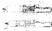
Referring now to Fig. 5-Fig. 8, second M/C and hand-held fire extinguisher 11 are described.This embodiment is similar to the embodiment shown in Fig. 1-4, and with opposite with high pressure extrusion extinguish material, its relies on spring pressure and a plunger ejection fire extinguishing cmpd.This fire extinguisher 110 comprises a shell 112, material storage tank 114, handle/trigger assembly 116, plunger, exhaust hose 120 and various other element, below with more detailed description.
This shell 112 comprises first and second part 112a and the 112b.The 112a of first comprises a semicolumn body wall 123 and a round bottom bottom part 122.Form a passage 124 in part 112a, it has first end 126 concentric with parts 122, and one second end 127, the second ends 127 are at mural margin 128 places.Ring- type connecting element 132 and 134 are set, have one respectively at each first and second ends, 126,127 place.Second portion 112b comprises a wall that is substantially similar to wall 123, and just it does not form passage and form elongated flexible tube along its length and preserves recess 137.Part 112a and 112b also form bindiny mechanism's (not having the label indication), allow two part 112a and 112b to be fixed together and form a shell cylinder, as shown in FIG..
With reference to Fig. 6 and Fig. 7, plunger 118 in the present embodiment comprises an independent wall that so forms, and promptly when plunger 118 is put in the storage tank 114, forms sealing between the inside face of side margins 146 and storage tank 114.As first embodiment, in this embodiment, plunger 118 should be formed by rubber or elastoplast, by and the friction coefficient materials with smaller that forms between the material of storage tank 114 form, make plunger 118 between first and second ends 143 and 144 of storage tank 114, to move, not hindered by contact therebetween.
Handle/trigger assembly 116 comprises a housing parts 148, binary pair 150, extendible portion 152, a spring 154 and a relatively large spring 156.Shell 148 has the top and the bottom that forms extendible portion shell 160 that form handle 158, and this bottom has a tangent line passage 171 and a bottom circular bottom wall 162.In addition, shell 148 forms a pillar 164, and binary pair 150 is installed on it, and ring-type extendible portion 166 is used to receive spring 154, extends axially ring flange 168 and is used to receive spring 156 from wall 162 extension downwards.
A hole 170 is formed on the center of wall 162, and is forming a path between passage 171 and chamber 172.Hole 174 is formed in the passage 171.
With reference to Fig. 5,6 and 7, binary pair 150 comprise a triggering part 178, extendible portion 180, one be used to receive and the ring-type extendible portion 182 of support spring 154 and the ratchet 184 of an end that is in extendible portion 180.Binary pair 150 is installed on the pillar 164, makes part 178 in abutting connection with handle 158 and be easy to depress.In addition, when pressure part 178 not, ratchet 184 by spring 154 by in 174 access passages 171 of hole.
In this embodiment, extendible portion 152 comprises an independent deformable resilient member, and shown in Fig. 6 and 7, when spring 156 was compressed, this element was crimped onto in the chamber 160, and when spring 156 expansions, it also can be the structure of an elongation.Extendible portion 152 comprises a plurality of along the equidistant recess that is provided with of its length direction, totally by label 186 expressions.The first end 152a on the extendible portion 152 is not connected with plunger 118, and the second end 152b is connected with plunger 118.
When installing, binary pair 150 is installed on the pillar 164, and spring 154 is between extendible portion 166 and 182, makes ratchet 184 pass through in 174 access passages 171 of hole by the elastic force of spring 154.Terminal 154b links to each other with plunger 118.Spring 156 is received by flange 168, makes an end of spring 156 lean against on the wall 162.Extendible portion 152 inserts by spring 156 and passage 171.Extendible portion 152 and plunger 118 shells 148, elongated end 152a is crimped onto shell 160 inside simultaneously by compression spring 156.Because elongated end 152a enters in the shell 160, ratchet 184 periodically is received in the recess 186, and extendible portion 152 is locked in transition condition.Finally, the recess 186 of the most close plunger 118 is aimed at ratchet 184, and ratchet 184 is housed in and wherein locks plunger 118, and spring 156 and extendible portion 152 are in carrying and do not trigger state.
Then, be full of fire extinguishing cmpd (supposing that spring 156 and plunger 118 need the space of 1/5th in about storage tank 114) in 4/5ths the chamber 172.If be ready, storage tank 114 is overfilled a bit, so that when assembly 116 was pressed on first end 143 of storage tank, some cmpds entered in the flexible pipe 120, in this case, when starting fire extinguisher 10, will spray immediately.Assembly 116 is fixed on first end 143 of storage tank 114, and plunger 118 is near first end and the top of cmpd chamber 172.
Be fixedly connected on the storage tank 114 by assembly 116, this storage tank can be placed on the connecting element 132, and sealing 142 forms liquid sealing at connecting element 132 with between exporting 138.Then, wall 112b links to each other with part 112a, makes shell 112 surround storage tank 114 fully.
Connecting element 192 links to each other with connecting element 134, by forced installation etc. excellent 120b is fixed on (see figure 6) in the passage 137.With reference to Fig. 5 and Fig. 8, a pin 194 is set, and on handle 158 and binary pair 150, forms the hole.When binary pair 150 is in when not triggering state, these alignment of a holes, insert pin 194 with guarantee binary pair 150 when the transportation not by accidental triggering.
In operation, when fire took place, the user picked up fire extinguisher 10 by handle 158, and fire extinguisher 10 is moved on near the zone of fire.When near fire, the user takes out pin 194 from handle 158, discharges binary pair 10 so that pressure part 178.The user takes out excellent 120b from passage 137.The excellent 120b at an end 196 places that hand-held and nozzle end 190 are relative, the user is the fiery bottom of nozzle end 190 sensings.When pressure part 178, the elastic force of binary pair 150 resistance springs 154 rotates around pillar 164, and ratchet 184 is deviate from from recess 186 and passage 171.When ratchet 184 was deviate from from recess 186, spring 156 and plunger 118 no longer were locked in an independent state.At this moment, spring 156 begins expansion, makes plunger 118 press to second end 144 of storage tank 114.172 inside are pressed into passage 124 to plunger 118 from the chamber the fire extinguishing cmpd successively, and spray to fire by flexible pipe 120 and nozzle end 190.
In addition, if when the user only thinks that the fire extinguishing cmpd of very few number sprays from chamber 172, but user's short time splenium divides 178.In this case, ratchet 184 is deviate from from recess 186, and spring 156 begins expansion extends extendible portion 152, makes ratchet 184 no longer aim at a recess 186.But, when unclamping part 178, force ratchet 184 to lean against on the extendible portion 152, punctual when 184 pairs on next recess 186 and ratchet, ratchet 184 enters recess 186, locks extendible portion 152 once more, spring 156 and plunger 118 are in unique state, up to pressure part 178 once more.
In addition, as first embodiment, use this embodiment, if when the user wants to spray cmpds all in the chamber 172, the user can long-time simply pressure part 178, makes spring 156 expansions, arrives terminal 144 up to plunger 118.
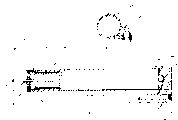
Referring now to Fig. 9-12, the fire extinguishing system 250 of an alternative embodiment of the invention is described.Two embodiment of this embodiment and front are different, and it will be installed in top ceiling, bonnet or the similar structures.In addition, this embodiment difference is that it is an automatic rather than manually operated fire extinguisher.In this embodiment 250, do not provide one independent must with guide rail 14 bonded assembly storage tanks 12, but in the guide rail of extruding, provide two storage tanks.This embodiment comprises a guide rail 252 and two storage tanks 254 and 256 except other element, will describe in detail below.
With reference to Figure 10,11 and 12, this guide rail 252 is an elongated extruder member, and is preferably made of aluminum, and it has the first end 252a and the second end 252b.This guide rail 252 forms three passages, comprises a storage tank passage 258, a fire extinguishing agent guide channel 26 and a cable lead-through 262.The radius of passage 258 is relatively large, make it can hold storage tank 254 and 256, middle part at guide rail 252, guide rail 252 forms an opening 264 (seeing Figure 17) between passage 258 and 262, in addition, guide rail 252 forms two openings 266,268 between passage 258 and 260, opening 266 is formed on end 252a, and opening 268 is formed on end 252b.
The 26S Proteasome Structure and Function of two storage tanks 254,256 is substantially the same, therefore only describes a storage tank 256 in detail.With reference to Figure 18, storage tank 256 comprises a housing 278, and it has an exit end 280 and a spring load end 282.Screw cap 284 sealing spring load ends also form a central opening 286.Plunger 290 and spring 288 are positioned at housing 278 inside, near cap 284.Plunger extension 292 is stretched out from opening 286 by the core extension of spring 288.This extendible portion forms a hole 294 perpendicular to its length direction.
Before ejection, plunger 280 is in the position that spring 288 is compressed fully, and extendible portion 292 stretches out opening 286.In this position, can there be a large amount of zones can store extinguish material.Before ejection, extendible portion 292 remains on the compressed state of spring with the plunger 290 that links to each other by pin 296 and cable 298.These pin 296 compressions are by hole 294, and cable 298 links to each other with extendible portion 292 by aperture 300 simultaneously.
With reference to Fig. 9-12, cable 298 extends into passage 262 by opening 264, stretches out passage 262 (see figure 9)s and links to each other with half fuse link 302.Another cable of second half of fuse link 302 304 links to each other, and this cable 304 extends to the opposite end of passage 262, and access passage 262 also extends to opening 264 along it, is connected to extendible portion 306 (see figure 10)s that link to each other with storage tank 254.
With reference to Figure 10 and 11, two end plug 308 and 310 are set, each end of end plug 308 of separating or 310 closed channels 258.Two end plug are substantially the same, only describe 310 in two end plug below.Plug 310 comprises the inner 314, an outer end 316 and an outside face 318, when plug 310 is housed in the end of passage 258, forms a tightening seal between the inside face of this outside face and passage 258.Plug 310 also forms a passage 312, and it has the arrival end and the outlet 318 that is arranged in perimeter surface 318 (being that passage 312 bends towards its exit end from its inlet) that are centered close to end 314.The inside face of passage 312 forms a peripheral notches 318 near its arrival end.When assembling, elastic seal 320 is arranged in the recess 318, and the arrival end of passage 312 receives the exit end 280 of storage tank 256.In addition, when assembling, the exit end of passage 312 should be aimed at outlet 268.Plug 308 and 310 can any prior art known mode be fixed on (comprising spiral, gluing or some other mechanical device) end of passage 258.
Except above-mentioned element, this embodiment should comprise that the installing mechanism (not shown) of some types remains on guide rail/reservoir component 250 with on the monitored zone.This system also comprises two thread head plugs 322,324, and they fixedly are housed in the screw channel end 274,276; And a plurality of bolt/nozzle assemblies 326 (seeing Figure 12), an assembly is used for each discharge orifice 272.
With reference to Fig. 9 and 10, when this embodiment was installed, the position shown in pin 296 should remain on made storage tank 254,256 not spray by accident.After go up in other zone that assembly 250 has been installed on the stove or some are monitored, can take out pin 296, making has fuse link 302 by all tension force (with other spring in the storage tank 254) stretching cable 298 and 304 in the spring 288 between cable.
In operation, when presence of fire, will make fuse link 302 fusing, discharge the tension force on the cable 298 and 304 from the excessive heat of big fire.At this moment, the spring in the storage tank 254 and 256 (being the spring 288 among Figure 11) expansion makes continuous plunger 290 leave cap 284.Then, the extinguish material in the storage tank 254,256 passes through outlet 280 and passage 312 access passages 260, and from exporting 272 ejection fire extinguishings.
Importantly, with the embodiment shown in Fig. 9-12, if guide rail 292 is made by relatively cheap extruded material, total system can be disposable use, can change this system simply after the ejection.This will not need the user to determine to load and reinstall how again this system.
Referring now to Figure 13,14 and 15, the fourth embodiment of the present invention 197 is described.This fire extinguisher 197 is similar with the 3rd above-mentioned embodiment, and it will be installed in top ceiling or the bonnet, and it is an automatic rather than manually operated fire extinguisher.This fire extinguisher 197 comprises 230,231, one temperature-sensitive Fuse assemblies 203 of 198,199, two end plug of 200, two storage tanks of a guide rail and a C clamp tool 224. Storage tank 198 and 199 inner member are substantially similar to the inner member of the storage tank among the 3rd embodiment, therefore are described no longer in detail.
In addition, with reference to Figure 15, inside face 206 also limits two fire extinguishing agent guide channels 204 and 205.Each passage 204 and 205 extending to the other end of guide rail along rail length than the end of short part (for example three to five inches) from guide rail.In an illustrated embodiment, in each passage 204 and 205, form two holes, four holes altogether by guide rail 200.These holes are generally by label 208 expressions.And, best, identical nozzle as shown in Figure 12 is set, a nozzle is used for whenever=each independent hole 208, makes the material of flowing through wherein can point to specific direction.
With reference to Figure 13 and 14, Fuse assembly 203 comprises a temperature-sensitive fuse link 209 that is installed in the fuse link shell 210.When ambient temperature arrives predetermined threshold value, fuse link 209 fusing.Shell 210 has two sidewalls (being pillar) 211,212 and upper and lower wall 213,214 respectively.The inside face 215 of wall 213 forms a pressure load-bearing surface, and it is a centralized positioning recess 216.Main element or attaching parts 217 whole being connected on the shell 210 that below wall 214, extends.(for example, by spiral, clasp, welding, crimping or other method well known in the prior art) in the hole 207 can be fixed and be housed in tightly to the structure of this attaching parts 217.Attaching parts 217 forms a passage 218, and this passage 218 extends downwards by attaching parts 217 from the inside face of lower wall 214.
The adaptor union of binary pair bar 219 forms is positioned in the passage 218, and has a near-end and a far-end 220,221 respectively.Near-end 220 forms the second fuse link receiving surface of recess 222 forms, and this recess 222 is similar to recess 215.Fuse link 209 is housed between recess 216 and 222, and is in when mounted under the great pressure.When accommodating like this, far-end 221 extends below attaching parts 217.
C clamp tool 224 comprise two parallel legs and one the leg end is linked together and cross therebetween distance back member.Recess 225 is formed on the middle part of back member.
Wide from storage tank 198 and 199 extendible portion 226 and the extendible portions 292 227 to the three embodiment that extend.In addition, these extendible portions 226 and 227 respectively form a recess 228,229 respectively.
With reference to Figure 15, end cap 230 is identical with the end cap shown in Figure 10 with 231, and each forms a passage 232,233 respectively, and when assembling, this passage receives the storage tank 198 of a vicinity or 199 outlet at one end.Crooked usually 90 degree of each passage 232,233 or wide-angle more make the opposite end radially rather than axially open.When normal mounting, when end plug 230 and 231 was fixed in the opposite end of guide rail 200, passage 232 and 233 should be at passage 204 and 205 split sheds.
When assembling, storage tank 198 and 199 is positioned at passage 201 inside, and their extendible portion 226 and 227 extends below flange 202.To pressing down C clamp tool 224, make in its end of hanging down each be housed in the independent recess 228,229.In this position, when the C clamp tool 224 in recess 225 was exerted pressure, C clamp tool 224 made extendible portion 226 and 227 remain on latched position.With the C clamp tool 224 of such location, make the end of hanging down 221 of bar 219 be housed in the recess 225, and exert pressure thereon.Then, end cap 230 and 231 is fixed in the end of guide rail 200 in any known mode in the prior art, makes the storage tank outlet be housed in passage 232 and 233, the opposite end of these passages is at passage 204 and 205 split sheds.
After assembling fire extinguisher 197 as mentioned above, this fire extinguisher can any known mode of the prior art be installed on the monitored zone, if be provided with nozzle in outlet 208, this nozzle can arrange like this that promptly they can point to specific easy fire area.When so located, Fuse assembly 203 should substantial horizontal (seeing Figure 13), makes the heat that rises from the monitoring area surround fuse link 209.
When presence of fire, rise and surround fuse link 209 from the big fire heat.When heat made fuse link 209 fusing above threshold level, fuse link 209 was destroyed.At this moment, bar 219 no longer presses downward in the recess 225, enters in the fuse link shell 210 so bar 219 rises.Corresponding to moving of bar 219, C clamp tool 224 also gets loose, and makes extendible portion 226 and 227 move into storage tank 198 and 199 inside by the spring (not shown).Force the fire extinguishing cmpd in storage tank 198 and 199 to export access passage 232 and 233 by storage tank by plunger, access passage 204 and 205 sprays through exporting 208 from guide rail 200 again.
Therefore, it should be noted that, simple, reliable, a cheap fire extinguisher has been described, it is in light weight, can form a lot of different shapes, does not need pressure gauge, can any direction and be independent of gravity operated, can partly spray, one " soft contact " spraying is provided, but and automatic or manual operation.
Should be appreciated that above-mentioned device only is an example, do not limit the scope of the invention that the various modifications that those skilled in the art carried out all fall within the scope of the invention.For example, has an extension that a plurality of recesses are arranged when being described to the handheld manual fire extinguisher, so that when not spraying all fire extinguishing cmpds as required, very clear, the present invention will comprise a system, wherein the quantity of these meterings can not be ejected, and all tankages must spray immediately.In addition, the present invention also comprises such system, and wherein the ratchet extension will comprise an independent rigid material spare.And although not shown, automatic fire extinguisher system can comprise a mechanism, and when detecting fire, this system also can start an alarm, and the indication fire takes place.In addition, although described all most preferred embodiments, as circular plunger and cylindrical oil tank or container that the fire extinguishing cmpd is housed, very clear, the present invention is not limited to this, on the contrary, the present invention includes plunger with difformity and size and all embodiment of storage tank.For example, but this plunger and storage tank rectangle, leg-of-mutton, polygonal or the like.In fact, in many application, can be the fire extinguisher (for example, in the cover of stove, on the top ceiling in room or the like) of a non-cylindrical shape.And although toply described two trigger mechanisms, very clear, the automatic trigger mechanism of any kind can be used in the present invention.In addition, fire extinguisher of the present invention can be enough big to spray the fire that enough fire extinguishing cmpds put out big room.For this reason, this fire extinguisher can be installed in the top ceiling, in the wall or the floor, have fuse link and one or more outlet of an exposure.And although the fixed fire extinguisher of explanation is full automatic, this fire extinguisher can comprise a manual release mechanism, is used for the manual triggers fire extinguisher when detecting fire.
Claims (27)
1, a kind of device by the extinguish material fire extinguishing, this device comprises:
A container, this container forms a usable material chamber, and it has first and second ends, and forms an outlet at least at second end;
The plunger that in this container, can between first and second ends, move;
A pusher is used for optionally by usable material chamber from first end to the second end mobile plunger; And
A sealing arrangement that is used to export can be operated the sealing device and make extinguish material through outlet.
2, according to the described device of claim 1, it is characterized in that, this pusher comprises a bias box, be used for plunger is pressed to second end, and a binary pair that links to each other with plunger, it can move between trigger position and non-trigger position at least, at non-trigger position, binary pair remains in the usable material chamber plunger, and at trigger position, binary pair makes bias box shift to second end to plunger.
According to the described device of claim 2, it is characterized in that 3, this bias box is a spring.
4, according to the described device of claim 3, it is characterized in that, this binary pair comprises an elongated joggle piece, it operationally links to each other with in the spring at least one with plunger, this joggle piece has a plurality of openings, but this binary pair also comprises a shift-in opening or the ratchet that shifts out from opening, optionally meshing joggle piece, and prevents the motion of spring and plunger.
According to the described device of claim 4, it is characterized in that 5, this joggle piece is an elongated ratchet members.
6, according to the described device of claim 4, it is characterized in that, also comprise a handle that is fixed on the container, this handle forms handle chamber, joggle piece and spring to small part is arranged in handle chamber, ratchet extends by handle, so as by user's finger manipulation from the engagement of joggle piece shift out ratchet, discharge plunger.
According to the described device of claim 6, it is characterized in that 7, this ratchet is pressed with joggle piece and meshes.
According to the described device of claim 7, it is characterized in that 8, this joggle piece to small part is wound in the handle chamber.
9, according to the described device of claim 1, it is characterized in that, also comprise the liquid fire extinguishing material in the container.
10, according to the described device of claim 1, it is characterized in that, also comprise a liquid discharge nozzle in described exit.
According to the described device of claim 1, it is characterized in that 11, the sealing device is opened corresponding to the pressure in the container.
According to the described device of claim 11, it is characterized in that 12, the sealing device is frangible, plunger movement makes material production pressure.
According to the described device of claim 1, it is characterized in that 13, this plunger is a piston, this container is columniform, and the sidepiece of this piston packing container leaks by piston to prevent material.
14, according to the described device of claim 1, it is characterized in that, also comprise a cap that is used to export that can re-cover tightly after opening.
15, according to the described device of claim 2, it is characterized in that, also comprise being used for this container is installed in the erecting device above the monitored zone, but this equipment also comprises the heat sensitive sensor of a sense ambient temperature, when ambient temperature exceeds maxim, make binary pair to trigger position.
16, according near the described device that is installed in the monitoring area of claim 1, it is characterized in that this device also comprises:
Independent guide rail with certain-length and an inwall, this inwall forms the guide rail chamber with first and second ends, and second end forms an opening, and the guide rail chamber of this opening and formation is used for receiving vessel, and second end of this container is in abutting connection with second end of guide rail chamber; And
An end plug, it is housed in after container is positioned in the guide rail chamber interior in second end of guide rail chamber, this end plug forms has the plug channels of first and second ends, and first end of formation is used for the opening of airtight container, and second end is used in reference to guarded region.
17, according to the described device of claim 16, it is characterized in that, this guide rail also forms a fire extinguishing agent guide channel that is in the guide wall, and at least one is in the guide rail outlet in this passage, guarded region is pointed in this guide rail outlet, and second end opening of this plug channels is in the fire extinguishing agent guide channel.
According to the described device of claim 17, it is characterized in that 18, this guide channel is formed in the inside face of guide rail inwall, the outer wall of this guide channel and container forms the fire extinguishing agent guide channel together.
According to the described device of claim 1, it is characterized in that 19, this container to small part is transparent.
According to the described device of claim 1, it is characterized in that 20, this container is made of plastics.
According to the described device of claim 1, it is characterized in that 21, this container is elongated.
According to the described device of claim 21, it is characterized in that 22, at least two feet in this container is long.
According to the described device of claim 1, it is characterized in that 23, the shape of this container and plunger is a rectangle.
According to the described device of claim 1, it is characterized in that 24, the shape of this container and plunger is leg-of-mutton.
According to the described device of claim 1, it is characterized in that 25, the shape of this container and plunger is oval-shaped.
26, according to the described device of claim 1, it is characterized in that, also comprise two material discharge nozzles at opening part.
According to the described device of claim 1, it is characterized in that 27, this extinguish material comprises a kind of liquid fire extinguishing material.
Applications Claiming Priority (2)
| Application Number | Priority Date | Filing Date | Title |
|---|---|---|---|
| US08/922,177 US5992531A (en) | 1997-09-02 | 1997-09-02 | Fire extinguisher |
| US08/922,177 | 1997-09-02 |
Publications (2)
| Publication Number | Publication Date |
|---|---|
| CN1272829A true CN1272829A (en) | 2000-11-08 |
| CN1141996C CN1141996C (en) | 2004-03-17 |
Family
ID=25446637
Family Applications (1)
| Application Number | Title | Priority Date | Filing Date |
|---|---|---|---|
| CNB988097788A Expired - Fee Related CN1141996C (en) | 1997-09-02 | 1998-09-02 | Fire extinguisher |
Country Status (9)
| Country | Link |
|---|---|
| US (1) | US5992531A (en) |
| EP (1) | EP1032539A4 (en) |
| JP (1) | JP2001514059A (en) |
| CN (1) | CN1141996C (en) |
| AU (1) | AU757387B2 (en) |
| BR (1) | BR9812165A (en) |
| CA (1) | CA2302373C (en) |
| IL (1) | IL134846A (en) |
| WO (1) | WO1999011568A1 (en) |
Cited By (2)
| Publication number | Priority date | Publication date | Assignee | Title |
|---|---|---|---|---|
| CN105597252A (en) * | 2016-03-08 | 2016-05-25 | 王晓勇 | Portable high-pressure water mist fire extinguisher |
| CN110507929A (en) * | 2019-08-30 | 2019-11-29 | 北京吉时开启智能科技有限公司 | The double startup spraying fire extinguisher of electric automobile battery box |
Families Citing this family (17)
| Publication number | Priority date | Publication date | Assignee | Title |
|---|---|---|---|---|
| US6340058B1 (en) | 2000-05-30 | 2002-01-22 | Stephen M. Dominick | Heat triggering fire suppressant device |
| GB0017153D0 (en) | 2000-07-12 | 2000-08-30 | Powell Robert | Extinguishing apparatus |
| US6360825B1 (en) | 2000-08-08 | 2002-03-26 | Randall Padgett | Automatic fire extinguisher system for use on cookstoves and ranges |
| US20020189824A1 (en) * | 2001-05-04 | 2002-12-19 | Ezekiel Joseph | System for fire extinguishing |
| SE519852C2 (en) * | 2002-02-14 | 2003-04-15 | Dafo Brand Ab | Extinguishing media and systems with containers |
| US20050109793A1 (en) * | 2003-11-25 | 2005-05-26 | Thomas John E. | Low product indicator for use with a tablet chlorinator |
| US7147061B2 (en) * | 2005-05-13 | 2006-12-12 | Future Innovation Trading, Inc. | Fire extinguisher kit, device and method of using same |
| WO2008103282A1 (en) | 2007-02-16 | 2008-08-28 | Nusbaum Michael J | Self-contained automatic fire extinguisher |
| CN202236979U (en) | 2011-09-28 | 2012-05-30 | 陕西坚瑞消防股份有限公司 | Portable fire extinguishing apparatus |
| CN202236978U (en) | 2011-09-28 | 2012-05-30 | 陕西坚瑞消防股份有限公司 | Portable fire extinguisher |
| CN202236980U (en) | 2011-09-28 | 2012-05-30 | 陕西坚瑞消防股份有限公司 | Portable fire extinguishing apparatus |
| US9010313B2 (en) | 2011-10-11 | 2015-04-21 | Conrad S. Mikulec | Cookery air purification and exhaust system |
| US9255714B2 (en) | 2011-10-11 | 2016-02-09 | Conrad S. Mikulec | Cookery air purification and exhaust system |
| US8517117B2 (en) | 2011-10-13 | 2013-08-27 | Conrad S. Mikulec | Range hood fire suppression system with visible status indication |
| CN103845830B (en) * | 2014-03-31 | 2016-02-10 | 徐鹏 | A kind of automatic fire extinguisher for self-burning of vehicle |
| CA2993241C (en) * | 2015-07-28 | 2023-12-12 | Globe Fire Sprinkler Corporation | Preaction sprinkler valve assemblies, related dry sprinkler devices and fire protection sprinkler systems |
| US10470554B2 (en) * | 2017-05-11 | 2019-11-12 | Creative Law Enforcement Resoures, Inc. | Portable hydration system with integrated circulatory and heating system |
Family Cites Families (9)
| Publication number | Priority date | Publication date | Assignee | Title |
|---|---|---|---|---|
| US984481A (en) * | 1910-07-25 | 1911-02-14 | Robert Hickish | Grease-cup. |
| US1233290A (en) * | 1915-10-29 | 1917-07-10 | Jardine Mfg Corp | Fire-extinguishing device. |
| US1366873A (en) * | 1920-05-28 | 1921-01-25 | Robert G Carpenter | Fire-extinguishing device |
| US1463518A (en) * | 1922-10-21 | 1923-07-31 | Emory M Thomas | Gasoline gun |
| US4083477A (en) * | 1976-08-09 | 1978-04-11 | Zetterberg Niklas F | Baiting tool for storing and dispensing fish bait |
| US4218013A (en) * | 1978-08-11 | 1980-08-19 | Davison Charles A | Shower head fluid dispenser |
| US4733799A (en) * | 1986-02-24 | 1988-03-29 | Wiskur Darrell D | Water cannon toy or like device |
| US4979572A (en) | 1987-01-20 | 1990-12-25 | Mikulec Conrad S | Fire extinguisher installation |
| US5199614A (en) * | 1991-08-08 | 1993-04-06 | Lincoln | Grease gun auto-pull follower apparatus |
-
1997
- 1997-09-02 US US08/922,177 patent/US5992531A/en not_active Expired - Lifetime
-
1998
- 1998-09-02 CN CNB988097788A patent/CN1141996C/en not_active Expired - Fee Related
- 1998-09-02 BR BR9812165-0A patent/BR9812165A/en not_active Application Discontinuation
- 1998-09-02 WO PCT/US1998/018258 patent/WO1999011568A1/en active IP Right Grant
- 1998-09-02 EP EP98943525A patent/EP1032539A4/en not_active Withdrawn
- 1998-09-02 CA CA002302373A patent/CA2302373C/en not_active Expired - Fee Related
- 1998-09-02 JP JP2000508618A patent/JP2001514059A/en active Pending
- 1998-09-02 AU AU91295/98A patent/AU757387B2/en not_active Ceased
- 1998-09-02 IL IL13484698A patent/IL134846A/en not_active IP Right Cessation
Cited By (2)
| Publication number | Priority date | Publication date | Assignee | Title |
|---|---|---|---|---|
| CN105597252A (en) * | 2016-03-08 | 2016-05-25 | 王晓勇 | Portable high-pressure water mist fire extinguisher |
| CN110507929A (en) * | 2019-08-30 | 2019-11-29 | 北京吉时开启智能科技有限公司 | The double startup spraying fire extinguisher of electric automobile battery box |
Also Published As
| Publication number | Publication date |
|---|---|
| CA2302373C (en) | 2007-11-13 |
| US5992531A (en) | 1999-11-30 |
| WO1999011568A1 (en) | 1999-03-11 |
| BR9812165A (en) | 2001-12-18 |
| IL134846A (en) | 2004-01-04 |
| AU9129598A (en) | 1999-03-22 |
| WO1999011568A9 (en) | 1999-05-20 |
| EP1032539A1 (en) | 2000-09-06 |
| CA2302373A1 (en) | 1999-03-11 |
| JP2001514059A (en) | 2001-09-11 |
| EP1032539A4 (en) | 2002-07-03 |
| AU757387B2 (en) | 2003-02-20 |
| IL134846A0 (en) | 2001-05-20 |
| CN1141996C (en) | 2004-03-17 |
Similar Documents
| Publication | Publication Date | Title |
|---|---|---|
| CN1141996C (en) | Fire extinguisher | |
| US8955609B2 (en) | Storage tank fire supression system | |
| US9155927B2 (en) | Self-contained self-actuated modular fire suppression unit | |
| US5881819A (en) | Fire extinguisher | |
| CN101965302B (en) | Apparatus for control of distance between aerosol dispenser and target at which it may be directed | |
| JP4866316B2 (en) | Residential fire extinguisher | |
| KR102050140B1 (en) | Hybrid extinguishing system for fire suppression of bus engine room | |
| US20090050339A1 (en) | System and method for extinguishing a fire | |
| JP2006288688A (en) | Automatic fire extinguishing device | |
| KR102082342B1 (en) | Hand-Operated Type Fire Extinguisher | |
| CN210250959U (en) | Induction type automatic spraying fire-fighting system applied to indoor security field | |
| US20110114644A1 (en) | Pressure release button and tool for propane cylinders | |
| CN218607830U (en) | Extinguishing device convenient to install fast | |
| MXPA00002205A (en) | Fire extinguisher | |
| KR102288618B1 (en) | Education apparatus for experiencing dust explosion | |
| JPWO2003043700A1 (en) | Automatic fire extinguisher | |
| CN216536652U (en) | Fire engineering is with preventing firing fire extinguisher | |
| EP0814211B1 (en) | Flame extinguisher for a free-head sewer | |
| KR200321508Y1 (en) | Automatic fire extinguisher activated by detonator | |
| KR200204646Y1 (en) | A fire extinguisher | |
| KR20110104643A (en) | Powder type automatic fire extinguisher | |
| CN201101843Y (en) | Powerful automatic fire extinguisher capable of self-checking | |
| GB2599419A (en) | ASAFEAS- A Self-Activating Fire Extinguisher and Alarm System for appliances | |
| JP6350844B2 (en) | Conveyor roller with jetting function | |
| EP3530325A1 (en) | Fire extinguisher |
Legal Events
| Date | Code | Title | Description |
|---|---|---|---|
| C06 | Publication | ||
| PB01 | Publication | ||
| C10 | Entry into substantive examination | ||
| SE01 | Entry into force of request for substantive examination | ||
| C14 | Grant of patent or utility model | ||
| GR01 | Patent grant | ||
| C19 | Lapse of patent right due to non-payment of the annual fee | ||
| CF01 | Termination of patent right due to non-payment of annual fee |