CN1269267C - Card connector assembly with improved ejection device - Google Patents
Card connector assembly with improved ejection device Download PDFInfo
- Publication number
- CN1269267C CN1269267C CNB018080014A CN01808001A CN1269267C CN 1269267 C CN1269267 C CN 1269267C CN B018080014 A CNB018080014 A CN B018080014A CN 01808001 A CN01808001 A CN 01808001A CN 1269267 C CN1269267 C CN 1269267C
- Authority
- CN
- China
- Prior art keywords
- card
- cam path
- support
- sliding members
- ejecting
- Prior art date
- Legal status (The legal status is an assumption and is not a legal conclusion. Google has not performed a legal analysis and makes no representation as to the accuracy of the status listed.)
- Expired - Fee Related
Links
Images


Classifications
-
- H—ELECTRICITY
- H01—ELECTRIC ELEMENTS
- H01R—ELECTRICALLY-CONDUCTIVE CONNECTIONS; STRUCTURAL ASSOCIATIONS OF A PLURALITY OF MUTUALLY-INSULATED ELECTRICAL CONNECTING ELEMENTS; COUPLING DEVICES; CURRENT COLLECTORS
- H01R12/00—Structural associations of a plurality of mutually-insulated electrical connecting elements, specially adapted for printed circuits, e.g. printed circuit boards [PCB], flat or ribbon cables, or like generally planar structures, e.g. terminal strips, terminal blocks; Coupling devices specially adapted for printed circuits, flat or ribbon cables, or like generally planar structures; Terminals specially adapted for contact with, or insertion into, printed circuits, flat or ribbon cables, or like generally planar structures
- H01R12/70—Coupling devices
-
- G—PHYSICS
- G06—COMPUTING; CALCULATING OR COUNTING
- G06K—GRAPHICAL DATA READING; PRESENTATION OF DATA; RECORD CARRIERS; HANDLING RECORD CARRIERS
- G06K13/00—Conveying record carriers from one station to another, e.g. from stack to punching mechanism
- G06K13/02—Conveying record carriers from one station to another, e.g. from stack to punching mechanism the record carrier having longitudinal dimension comparable with transverse dimension, e.g. punched card
- G06K13/08—Feeding or discharging cards
- G06K13/0806—Feeding or discharging cards using an arrangement for ejection of an inserted card
-
- G—PHYSICS
- G06—COMPUTING; CALCULATING OR COUNTING
- G06K—GRAPHICAL DATA READING; PRESENTATION OF DATA; RECORD CARRIERS; HANDLING RECORD CARRIERS
- G06K7/00—Methods or arrangements for sensing record carriers, e.g. for reading patterns
- G06K7/0013—Methods or arrangements for sensing record carriers, e.g. for reading patterns by galvanic contacts, e.g. card connectors for ISO-7816 compliant smart cards or memory cards, e.g. SD card readers
- G06K7/0034—Methods or arrangements for sensing record carriers, e.g. for reading patterns by galvanic contacts, e.g. card connectors for ISO-7816 compliant smart cards or memory cards, e.g. SD card readers the connector being capable of simultaneously receiving a plurality of cards in the same insertion slot
-
- H—ELECTRICITY
- H01—ELECTRIC ELEMENTS
- H01R—ELECTRICALLY-CONDUCTIVE CONNECTIONS; STRUCTURAL ASSOCIATIONS OF A PLURALITY OF MUTUALLY-INSULATED ELECTRICAL CONNECTING ELEMENTS; COUPLING DEVICES; CURRENT COLLECTORS
- H01R13/00—Details of coupling devices of the kinds covered by groups H01R12/70 or H01R24/00 - H01R33/00
- H01R13/62—Means for facilitating engagement or disengagement of coupling parts or for holding them in engagement
- H01R13/629—Additional means for facilitating engagement or disengagement of coupling parts, e.g. aligning or guiding means, levers, gas pressure electrical locking indicators, manufacturing tolerances
- H01R13/633—Additional means for facilitating engagement or disengagement of coupling parts, e.g. aligning or guiding means, levers, gas pressure electrical locking indicators, manufacturing tolerances for disengagement only
Landscapes
- Engineering & Computer Science (AREA)
- Physics & Mathematics (AREA)
- General Physics & Mathematics (AREA)
- Theoretical Computer Science (AREA)
- Artificial Intelligence (AREA)
- Computer Vision & Pattern Recognition (AREA)
- Coupling Device And Connection With Printed Circuit (AREA)
- Details Of Connecting Devices For Male And Female Coupling (AREA)
Abstract
A card connector assembly for receiving a card member is provided with an eject device wherein the eject device is assembled directly onto the support frame of the card connector assembly to thereby reduce the number of components, the number of assembly steps and the resultant manufacturing costs of the connector assembly. The card connector assembly comprises a card guide portion (5a), a connector portion (9) to be connected to the card member, a support frame (3) continuous with both the card guide portion and the connector portion and an eject device (2). The eject device (2) comprises a slide member (22) slidably movable along the support frame (3), a movable lever (35) operating in accordance with movement of the slide member (22) for moving the card in a direction away from the card connector (7), and a cam mechanism (10) for defining the sliding range of the slide member (22). A part of the cam mechanism (10) is provided directly in the support frame (3).
Description
Technical field
The present invention relates to for example card connector assembly of PC card of receiving card device, relate more specifically to have the card connector assembly of device for ejecting, it is characterized in that device for ejecting directly is contained in the support of connector assembly, thereby reduce the number of spare parts of connector assembly and synthetic assembly and reduce manufacturing cost.
Background technology
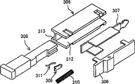
The card connector that device for ejecting is housed is known, and one of them example is referring to the flat 11-219756 of Japanese patent application communique.In this card connector, as shown in figure 10, card 300 is packed into and is drawn off along the direction shown in the arrow.Device for ejecting 302 startings that when needing ejecting card, are connected with release lever 301.Figure 11 is the perspective view of this connector, represents scanning of device for ejecting 302.Figure 12 is the decomposition diagram of device for ejecting 302.Can clearly be seen that from these figure device for ejecting 302 forms a tube, therefore after device for ejecting 302 is assembled into tube, is fixed on the support 304 of connector.As shown in figure 12, device for ejecting 302 comprises shell 305, lid 306, ejection rod 307, button 308, helical spring 310, spring 311 and contact chip 309.Have the receiving slit 312 of button 308 in the shell 305 and shell 305 is fixed to holddown groove 313 on the support 304.Other part comprises button 308, is contained on the shell 302.After the assembling, utilize holddown groove 313 that device for ejecting 305 is fixed on the support 304.
In this legacy card connector, because device for ejecting 302 is tubulars, therefore can in an independent step, assemble device for ejecting, become an independent assembling process.Like this, during device for ejecting and when the needs device for ejecting, just device for ejecting 302 can be installed on the support 304 or with it improvement if desired.
On the other hand, because the structure of this known device for ejecting 302 is independent tube,, has increased the manufacturing cost of this structure and part has been fitted together required workman so used a lot (seven) parts.
Summary of the invention
General objects of the present invention provides card connector assembly, and wherein device for ejecting can directly be contained on the support, thereby reduces the quantity of part, correspondingly by reducing the integrated cost that manufacturing, stock and assembly cost reduce connector assembly.
The invention provides a kind of two card connector assemblies of the card element of plane earth insertion generally that receive and eject, comprising: a U-shaped support, have two arm portions that are positioned on the relative both sides of support, be used for the guide card element and cooperate with card connector assembly; And a connector part, have the contact that is used for the contact contact corresponding with the card element; And two device for ejecting, be used for the ejecting card element, each device for ejecting is contained on the part of an arm portion of support, and comprise a sliding members that moves slidably along described support, a button that is integrated on sliding members one end, hingedly be contained in the support upper edge and leave the carriage release lever that the card connector direction moves described card, and limit the cam mechanism that sliding members slides in support, wherein the part of cam mechanism is formed directly on the described support, it is characterized in that: described cam mechanism comprise one with integrally formed first cam path of one of two arm portions, pin plate with first pin that can in described cam path, move, one is used for towards first spring element of cam path clamping pin plate, first helical spring of the position bias slide element that is used to draw back, and first retained part that is used for described pin plate is clamped in cam path that in the groove of sliding members, forms, wherein, the muscle part on two parallel surfaces with the card element that is parallel to insertion is protruding from a side surface of described arm portion, and described first cam path is formed in the surface of muscle part, makes the cam path of winning be parallel to the plane that the card element inserts.
According to the present invention, the receiving card element for example card connector assembly of PC card comprises: the card targeting part, comprise card connector and matrix connector connector part, with block support and the device for ejecting that targeting part and connector part all are connected, it is characterized in that device for ejecting comprises: sliding members, can move along support; Carriage release lever moves along with moving of sliding members, is used for moving card along the direction of leaving connector; Cam mechanism is used to limit the sliding scale of sliding members, it is characterized in that the part of cam mechanism directly is contained on the support.
Support has along the sliding members gathering sill of sliding members moving direction extension and along blocking the card targeting part that moving direction extends.This structure effectively utilizes support as the integrated part in the device for ejecting.
Cam mechanism comprises the cam path that is located immediately in the support, has the pin plate of the pin that moves in cam path, to the flexible member of cam path bias voltage pin plate and the helical spring of the position bias slide plate of drawing back.Under this structure, can simplify the structure of cam mechanism.
Retained part clamping pin plate moves pin plate along certain angle in limited range in cam path.This structure has been saved being connected between pin plate and the sliding members, thereby has further simplified the structure of cam mechanism.
Receive helical spring reception groove and be arranged in sliding members.This structure is convenient to helical spring is loaded in the sliding members, and device for ejecting is integrally formed in the compact structure as one.
At the bracket side mask muscle part is arranged, one surface is parallel to the surface of inserting card fully, has cam path on the surface of muscle part.Cam path is positioned at the surface of muscle part, makes card connector assembly not only reduce the quantity of part, also can do thinlyyer.
During the device for ejecting action, pin plate is along with sliding members retreats with preceding and then mobile, and cam path comprises first cam path that limits the pin plate progressive position, the 3rd cam path that limits second cam path of pin plate going-back position and connect first and second cam paths qualification pin plate lock position.The lock position of pin plate has ejected the back at card and has mispluged into being provided with for stoping ejection back card.
Preferably, support is made by molded resin, thereby the targeting part of the gathering sill of sliding members and card forms the part of support in forming process.And because support is formed from a resin, the conducting terminal of coupling part can directly be contained on the support.This structure has also improved manufacturing efficient and has finally reduced manufacturing cost.
Therefore, according to the present invention, device for ejecting directly is contained in the arm portion of support, can save irrelevant part like this, for example formerly uses in the device for ejecting of technology.As a result, reduce the number of spare parts of connector assembly, thereby correspondingly reduced the step of assembling, caused the reduction of connector assembly manufacturing cost.
To the description of card connector assembly according to the preferred embodiment of the invention, can understand other purpose of the present invention and advantage from following.These preferred embodiments are represented in the accompanying drawings.
Description of drawings
Feature of the present invention believes it is novel, embodies in the appended claims with particularity.Can be expressly understood the present invention and purpose and advantage in conjunction with the accompanying drawings and with reference to following detailed, same reference number is represented same part in the accompanying drawing, in the accompanying drawing:
Fig. 1 is the perspective view of the card connector of one embodiment of the invention;
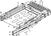
Fig. 2 is the partial, exploded perspective view of card connector assembly of the present invention;
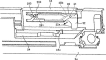
Fig. 3 is the enlarged perspective of the cam path that uses in the card connector assembly of the present invention;
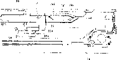
Fig. 4 is the plane graph of device for ejecting of the present invention;
Fig. 5 is the work sheet of cam mechanism of the present invention;
Fig. 6 is the work sheet of cam mechanism of the present invention;
Fig. 7 is the work sheet of cam mechanism of the present invention;
Fig. 8 is the work sheet of cam mechanism of the present invention;
Fig. 9 is the work sheet of cam mechanism of the present invention;
Figure 10 is the perspective view of the known card connector assembly of expression;
Figure 11 is scanning of the device for ejecting that uses in known card connector assembly;
Figure 12 is the decomposition diagram of device for ejecting in the known card connector assembly of Figure 10.
Embodiment
One embodiment of the present of invention are shown among Fig. 1, and two-layer PC card connector assembly of expression is used for receiving card among the figure, PC card for example, and card device for ejecting 2 is housed.Fig. 2 is the enlarged perspective of card connector assembly 1 basic structure.
As shown in Figure 1, card connector assembly 1 is rectangle substantially.Connector assembly 1 is two-layer or the dual-port type, and therefore two card device for ejecting 2 similarly are contained in levels or upper and lower port.Connector body comprises the support 3 of basic U-shaped, as shown in Figure 2.Metal-back 4 (only having one in Fig. 1) is used to cover the top and the bottom of support 3.Support 3 is preferably made by molded plastic resin.
Device for ejecting 2 directly is contained in the outside of 3 one arm portion 3a of support.Device for ejecting 2 comprises: sliding members 22 is contained in the gathering sill 23 and 24 of support arm part 3a slidably; Button 21 is integrated on the end of sliding members; Movable bar 35 hingedly is contained on the support, moves card in response to the starting of sliding members 22 and mobile ejecting card and along the direction of leaving card connector 7; Cam mechanism 10 is used to limit the sliding scale of sliding members 22.Along the moving direction of sliding members with divide gathering sill 23 and 24 that muscle 25 extends between them, as shown in Figure 2.The part of cam mechanism 10 is located immediately on the arm portion 3a.
For the sake of clarity, a device for ejecting 2 will be described below.Sliding members 22 is rectangular element, has an integrated button 21 above, can move forward and backward in gathering sill 23 along the direction shown in the arrow A (Fig. 1).Prevent that device that sliding members 22 side direction separate with gathering sill 23 is between the side part and sliding members 22 of arm portion 3a, be to extend and be formed on rail shape bossing 25a and 25b on branch muscle 25 upper and lower surfaces, and on sliding members 22, have a protrusion tab 22a and cooperate with bossing 25a along the length direction of gathering sill.
The helical spring 26 of bias slide element 22 is contained between sliding members 22 and the arm portion 3a.Helical spring 26 is inserted among the reception groove 22b of sliding members 22.One end of helical spring 26 is in abutting connection with the wall surface that receives groove 22b, and the other end stops 27 on the arm portion 3a.Like this, when pushing sliding members 22, compression helical spring 26, thus produce reaction force in opposite direction.
Referring to Fig. 3-9 and Fig. 2, cam mechanism 10 comprises: the cam path 28 among the support 3 arm portion 3a; Pin plate 30 with pin 31, pin 31 is suitable for inserting in the cam path 28 and can moves therein; Be arranged in the clamping or the groove part 22c of sliding members 22, be used for clamping pin plate 30 and in limited range, move along certain angle; Be contained in the sheet spring 29 among the retained part 22c, be used for pushing pin plate 30 to cam path 28.End at pin plate 30 close pins 31 has head part 32.Be exposed at the front that opening 22d in pin plate 30 head part 32 is positioned at retained part.
The size of retained part 22c and shape can make the pin 31 of pin plate 30 move in cam path 28.Also can form the sliding members that integrates with sliding panel.
The whole thin profile of the position influence card connector assembly of cam path 28.Just, have muscle part 33 in the side of arm portion 3a, muscle part 33 has a plane surface and is parallel to the surface of inserting card fully, and cam path 28 is positioned at the surface of muscle part 33.In Fig. 2, show upper strata cam path 28.Lower surface in muscle part 33 also has cam path 28 (Fig. 3).
Cam path 28 comprises first cam path 281 that limits pin plate 30 progressive positions, the 3rd cam path 283 that limits second cam path 282 of pin plate 30 going-back positions and be connected the interim lock position that is used to limit pin plate 30 with first and second cam paths.The 3rd cam path allows card to eject the lock position that pin plate 30 is set in the back.
As shown in Figure 3, first cam path 281 and second cam path, 282 respectively corresponding " advancing " route L1 and " returning " route L2.The pin 31 of setting pin plate 30 makes it remain on starting end 28a at progressive position, the part of first cam path 281 on the sliding panel going-back position.
Because pin plate 30 is clamped among the retained part 22c of sliding members 22, pin plate 30 retreats together along with sliding members and advances.As shown in Figure 4, the rod 34 of operation carriage release lever 35 is arranged in arm portion 3a, can move along with moving of pin plate 30.One end 34b of rod 34 is connected on the carriage release lever 35 by hinged mode.Bar 35 is contained on the support 3, therefore can rotate around pivot section 35a.When progressive position at cam path 28 of the pin 31 of pin plate 30, the other end 34a of rod 34 and the claw portion 32a of head part 32 join.The slippage that is driven by sliding members 22 is pointed out from joining and is begun now to determine.But, in moving process, provide some loose, when sliding members 22 during at going-back position (position shown in Figure 1), between the end 34a of the claw portion 32a of head part 32 and rod 34 a spot of gap appears.
The operation of device for ejecting 2 ejecting cards is described below.The connection of Fig. 5-9 expression card ejection operation cam mechanism 10 is moved.
The initial position of the corresponding sliding members 22 of Fig. 5, wherein card does not also insert or blocks and just insert.In this case, sliding members 22 is moved to going-back position by helical spring 26, as shown in Figure 1.
After card inserts, the electric contact of terminal 9a of the contact of card and card connector 7.Under this condition, to press and sliding members 22 when advancing when button 21, pin plate 30 correspondingly advances along with moving of sliding members 22.This moment, helical spring 26 was compressed.And the pin 31 of pin plate 30 is prevented from moving to second cam path 282, because there is ledge surface 28b.As a result, pin 31 moves along first cam path 281 (being advance route L1), and the pawl 32a of head part 32 is in abutting connection with the end 34a of rod 34, as shown in Figure 6.
When sliding members 22 moves forward and helical spring 26 when being compressed, the pin 31 of pin plate 30 moves along first cam path 281 and promotes rod 34, as shown in Figure 7.As a result, carriage release lever 35 rotates by the direction shown in the arrow B around pivot section 35a, and the end of card is promoted by free end 35b, ejecting card.At this point, pin 3 stops returning of pin through ledge surface 28c.And under this condition, the contact of card disconnects electronics with the terminal 9a of card connector 7 and contacts ejecting card.
When mobile the stopping of sliding members 22, under the active force of the helical spring 26 of compression, sliding members 22 moves backward with pin plate 30.Ledge surface 28c stops returning of pin 31 and makes pin 31 move to the 3rd cam path 283 (Fig. 8) from first cam path 281.At this moment, cooperating between the claw portion 32a of pin plate 30 head part 32 and rod 34 the end 34a separates.Therefore, ejection or release condition that Here it is blocks.
When sliding members 22 turns back to its home position (shown in Figure 1), sliding members 22 is promoted once more and is advanced.This makes sliding members 22 and pin 31 return step part 28d through the prevention of the 3rd cam path 283 and moves to second cam path 282.Under this condition, when mobile the stopping of sliding members 22, sliding members 22 moves in the reaction force or the motive force effect lower edge direction of retreat of helical spring 26.Therefore, pin 31 is retracted its home position (Fig. 5) through second cam path 282 (being return route L2).
Therefore the invention provides simplification, but effective card connector assembly mechanically, be used for from ejecting card wherein.Just, device for ejecting 2 directly is contained on the arm portion 3a of support 3, makes sliding members 22 itself also as lid.Therefore, saved the part of picture shell or lid and so on, and needed in this cartridge type device for ejecting formerly.As a result, in the present invention, reduce the quantity of part and the step of assembling, correspondingly reduced manufacturing cost.And the cam path 28 of cam mechanism 10 is formed directly among the arm portion 3a of support 3, has further reduced the number of spare parts of cam mechanism and the quantity of number of assembling steps.And, gathering sill 23 and 24 and the targeting part 5 and 6 of card on support 3, so support is fully used, and saved the cost of device for ejecting.Cam mechanism 10 also comprise cam path 28, the pin plate 30 on the support 3 and be suitable for inserting pin 31 in the cam path 28, to cam path 28 promote the flat spring 29 (flexible member) of pin plates 30, along the helical spring 26 that turns back to the direction bias slide element 22 of going-back position.And support 3 is made by molded resin, thus gathering sill 23 and 24 and the card targeting part 5 and 6 can in the forming process of support, form.And because support 3 is formed from a resin, the conducting terminal 9a of connector part 9 comprises card connector 7 and matrix connector 8, can directly be contained in the support 3.
In a word, in card connector assembly of the present invention, device for ejecting directly is contained in the support, thereby can reduce the quantity of part and the quantity of number of assembling steps, and the manufacturing cost and the cost of inventory of corresponding reduction trimming connector assembly.
It should be understood that the present invention can be embodied in other the concrete form, and do not depart from spirit of the present invention or principal character.Therefore, it is illustrative that example of the present invention and embodiment are considered in all respects, rather than restrictive, and the present invention is not subjected to the restriction of details given here.
Claims (3)
1. one kind receives and ejects two card connector assemblies (1) of the card element of plane earth insertion generally, comprising:
A U-shaped support (3) has two arm portions (3a) that are positioned on the relative both sides of support, is used for the guide card element and cooperates with card connector assembly; And
A connector part (9) has the contact (9a) that is used for the contact contact corresponding with the card element; And two device for ejecting (2), be used for the ejecting card element, each device for ejecting is contained on the part of an arm portion of support, and comprise a sliding members (22) that moves slidably along described support, a button (21) that is integrated on sliding members one end, hingedly be contained in the support upper edge and leave the carriage release lever (35) that the card connector direction moves described card, and limit the cam mechanism (10) that sliding members slides in support, wherein the part of cam mechanism is formed directly on the described support
It is characterized in that:
Described cam mechanism comprise one with one of two arm portions integrally formed first cam path (28), pin plate (30) with first pin (31) that can in described cam path, move, first spring element (29) that is used for towards cam path clamping pin plate, first helical spring (26) of the position bias slide element that is used to draw back, and first retained part (22c) that is used for described pin plate is clamped in cam path that in the groove of sliding members, forms, wherein, the muscle part (33) on two parallel surfaces with the card element that is parallel to insertion is protruding from a side surface of described arm portion, and described first cam path is formed in the surface of muscle part, makes the cam path of winning be parallel to the plane that the card element inserts.
2. card connector assembly as claimed in claim 1 is characterized in that, described sliding members also comprises a reception groove (22b) in the groove that is formed on sliding members, is used for receiving and encasing described helical spring.
3. card connector assembly as claimed in claim 1 is characterized in that, second cam path is formed in another surface of muscle part, makes itself and first cam path form abreast and extend.
Applications Claiming Priority (3)
| Application Number | Priority Date | Filing Date | Title |
|---|---|---|---|
| JP110703/00 | 2000-04-12 | ||
| JP2000110703A JP2001307825A (en) | 2000-04-12 | 2000-04-12 | Connector for card |
| JP110703/2000 | 2000-04-12 |
Publications (2)
| Publication Number | Publication Date |
|---|---|
| CN1423851A CN1423851A (en) | 2003-06-11 |
| CN1269267C true CN1269267C (en) | 2006-08-09 |
Family
ID=18623172
Family Applications (1)
| Application Number | Title | Priority Date | Filing Date |
|---|---|---|---|
| CNB018080014A Expired - Fee Related CN1269267C (en) | 2000-04-12 | 2001-04-12 | Card connector assembly with improved ejection device |
Country Status (6)
| Country | Link |
|---|---|
| JP (1) | JP2001307825A (en) |
| KR (1) | KR100474019B1 (en) |
| CN (1) | CN1269267C (en) |
| AU (1) | AU2001253433A1 (en) |
| TW (1) | TW492587U (en) |
| WO (1) | WO2001080373A2 (en) |
Families Citing this family (2)
| Publication number | Priority date | Publication date | Assignee | Title |
|---|---|---|---|---|
| JP4404545B2 (en) * | 2002-12-27 | 2010-01-27 | ホシデン株式会社 | Card connector |
| TWI283500B (en) * | 2005-11-14 | 2007-07-01 | Fci Asia Technology Pte Ltd | Mechanism for ejecting a card |
Family Cites Families (3)
| Publication number | Priority date | Publication date | Assignee | Title |
|---|---|---|---|---|
| JP3368458B2 (en) * | 1997-06-03 | 2003-01-20 | 日本航空電子工業株式会社 | Card connector |
| CN1146083C (en) * | 1997-10-15 | 2004-04-14 | 姚立和 | Memory card cartridge socket |
| JP3701792B2 (en) * | 1998-04-10 | 2005-10-05 | アルプス電気株式会社 | Connector device |
-
2000
- 2000-04-12 JP JP2000110703A patent/JP2001307825A/en active Pending
-
2001
- 2001-04-12 CN CNB018080014A patent/CN1269267C/en not_active Expired - Fee Related
- 2001-04-12 AU AU2001253433A patent/AU2001253433A1/en not_active Abandoned
- 2001-04-12 WO PCT/US2001/012015 patent/WO2001080373A2/en not_active Application Discontinuation
- 2001-04-12 KR KR10-2002-7013714A patent/KR100474019B1/en not_active IP Right Cessation
- 2001-06-22 TW TW090205620U patent/TW492587U/en not_active IP Right Cessation
Also Published As
| Publication number | Publication date |
|---|---|
| TW492587U (en) | 2002-06-21 |
| KR20020087976A (en) | 2002-11-23 |
| AU2001253433A1 (en) | 2001-10-30 |
| JP2001307825A (en) | 2001-11-02 |
| CN1423851A (en) | 2003-06-11 |
| KR100474019B1 (en) | 2005-03-10 |
| WO2001080373A3 (en) | 2002-03-21 |
| WO2001080373A2 (en) | 2001-10-25 |
Similar Documents
| Publication | Publication Date | Title |
|---|---|---|
| CN1934579A (en) | Memory card connector | |
| CN1215609C (en) | Connector for card | |
| CN1226812C (en) | Connector for card | |
| CN1645673A (en) | Buckle connector for electronic apparatus and contactor therefor | |
| US7118395B2 (en) | Card connector locking member arrangement | |
| CN1947128A (en) | Memory card connector | |
| CN1407662A (en) | Connector of storage card | |
| CN1428898A (en) | Trip mechanism of card-used connector | |
| US20060166533A1 (en) | Card connector | |
| US20060003617A1 (en) | Card connector | |
| CN101030685A (en) | Ic card connector | |
| CN1411110A (en) | Card connector device | |
| US6948956B2 (en) | Electrical connector with module ejection system | |
| CN1882955A (en) | Memory card connector with card eject mechanism | |
| CN1585202A (en) | Memory card connector | |
| US6071135A (en) | Electrical card connector | |
| CN1269267C (en) | Card connector assembly with improved ejection device | |
| US6074227A (en) | Ejecting mechanism and a connector using the same | |
| KR100344504B1 (en) | Information processing medium connector with locking means | |
| CN1471048A (en) | Card slot assembly with electric-controllable ejection mechanism | |
| CN1638206A (en) | Card connector that can prevent both leaping-out and ejection failure of a card | |
| CN1310383C (en) | Plug connector assembly | |
| CN1947129A (en) | Low profile memory card connector | |
| CN1299398C (en) | Card connector allowing easy removal of a card after the card is ejected | |
| US6923665B2 (en) | Card connector |
Legal Events
| Date | Code | Title | Description |
|---|---|---|---|
| C06 | Publication | ||
| PB01 | Publication | ||
| C10 | Entry into substantive examination | ||
| SE01 | Entry into force of request for substantive examination | ||
| C14 | Grant of patent or utility model | ||
| GR01 | Patent grant | ||
| C17 | Cessation of patent right | ||
| CF01 | Termination of patent right due to non-payment of annual fee |
Granted publication date: 20060809 Termination date: 20110412 |