CN1268983A - Separating member for separating the tank bottom part from the rest of the tank - Google Patents
Separating member for separating the tank bottom part from the rest of the tank Download PDFInfo
- Publication number
- CN1268983A CN1268983A CN98808729A CN98808729A CN1268983A CN 1268983 A CN1268983 A CN 1268983A CN 98808729 A CN98808729 A CN 98808729A CN 98808729 A CN98808729 A CN 98808729A CN 1268983 A CN1268983 A CN 1268983A
- Authority
- CN
- China
- Prior art keywords
- separating member
- electrolyzer
- space
- separating
- solid
- Prior art date
- Legal status (The legal status is an assumption and is not a legal conclusion. Google has not performed a legal analysis and makes no representation as to the accuracy of the status listed.)
- Pending
Links
Images


Classifications
-
- C—CHEMISTRY; METALLURGY
- C25—ELECTROLYTIC OR ELECTROPHORETIC PROCESSES; APPARATUS THEREFOR
- C25C—PROCESSES FOR THE ELECTROLYTIC PRODUCTION, RECOVERY OR REFINING OF METALS; APPARATUS THEREFOR
- C25C7/00—Constructional parts, or assemblies thereof, of cells; Servicing or operating of cells
- C25C7/06—Operating or servicing
-
- C—CHEMISTRY; METALLURGY
- C25—ELECTROLYTIC OR ELECTROPHORETIC PROCESSES; APPARATUS THEREFOR
- C25C—PROCESSES FOR THE ELECTROLYTIC PRODUCTION, RECOVERY OR REFINING OF METALS; APPARATUS THEREFOR
- C25C7/00—Constructional parts, or assemblies thereof, of cells; Servicing or operating of cells
Abstract
The invention relates to a separating member for separating the bottom part of an electrolytic tank from the rest of the tank space in connection with the removal of solids (6) settled onto the bottom of the electrolytic tank (1). According to the invention, in the electrolytic tank (1) there are installed support and control members (10), which form the trajectory of the separating member (11, 21, 31), so that the separating member (11, 21, 31) can be inserted in the electrolytic tank (1) and removed therefrom via a space left in between at least one rear wall (7, 32) of the electrolytic tank (1) and the electrode (2) located nearest to said rear wall (7, 32).
Description
The present invention relates to a kind of separating member of removing the solid that produces in the electrolyzer, the other parts of bottom of electrolytic tank and groove being separated.
In electrolytic process, producing for example precipitating metals such as copper, nickel and zinc on the negative electrode that can be in being arranged at electrolyzer, they both can be from the metal anode that is dissolved in the electrolyzer, also can be from the metal ion that is dissolved in the electrolytic solution.Yet not all solid all precipitate on the cathode surface, for example the solid impurity that comprises in precious metal and the electrolytic solution.Therefore, be accompanied by the refining of metal process, various solids have been accumulated in the bottom of electrolyzer, must at any time they be removed away from groove, reason for example can be owing to contain valuable composition in the solid, precious metal for example, or because thicker solid accumulation is harmful to the obtained negative electrode purity of electrolytic process.
Usually, the solid that is accumulated in the electrolyzer is that part is very fine isolating at least, and only heavy slightly than electrolytic solution, thereby is difficult to these solids are separated from electrolytic solution.In electrolytic process, be very deleterious if solid begins circulation from bottom of electrolytic tank, because the chance that ends on the negative electrode of these solids is big especially subsequently, and this will cause the purity of the metal preparing to produce significantly to descend.
Usually, remove the solid that is accumulated in bottom of electrolytic tank and need interrupt whole electrolytic process, this has reduced the efficient of unit time, that is, and and the productivity of electrolysis plant.Therefore, removing solid must be at electrolytic solution, that is, the replacing procedure division of anode and negative electrode carries out, and this feasible replacing is complicated, slow, and restriction removal solid can only be by being undertaken by the described determined cycle of replacing alternation procedure.In addition, must at first remove a large amount of electrolytic solution from groove, and then it is backed in the groove, this plays deleterious effects to the quality of electrolytic solution usually, and brings many overworks.In solids management system, also to handle a large amount of electrolytic solution, these electrolytic solution must change into new, and may further handle harmful to solid.In addition, the manual electrolyzer that cleans makes this process increase labour intensity significantly, and for example because the splash effect of groove and the employee is caused infringement on the health owing to be contained in the composition in the spittle.And, almost be impossible handle automatically to electrolytic solution, because manual quantity of cleaning the required employee of electrolyzer, further increased in the electrolysis plant demand to the labor force.
The objective of the invention is to avoid the shortcoming of prior art, and realize a kind of advanced person's the separating member that is applicable to electrolyzer, so that the bottom of electrolyzer and the other parts of groove are kept apart, just solid can be removed from bottom of electrolytic tank thereby need not to upset electrolytic process basically.These main new features of the present invention are with clearly visible in the appended from behind claim.
Member the present invention in an electrolyzer, is preferably on the cell wall, and bracing member is installed, and they also lead to the path that is installed in the separating member in the electrolyzer except providing support.Described separating member is placed in wherein along the whole length of electrolyzer basically, approach the bottom of groove substantially, when being formed at solid on the bottom land, removal uses, so that separating member separates the electrolytic solution of liquid state with the solid that is deposited to bottom of electrolytic tank, prepare to remove.
Separating member according to the present invention is made by the flexible connecting structure parts, and these parts form the surface of basic sealing, can also be crooked mutually.Therefore, need not on groove to make any special opening, only simply by on the surface of liquid electrolyte and and then under the surface substantially near the back wall guided separating member of electrolyzer, in the electrolyzer of just separating member can being packed into.
When needs are removed the solid that is accumulated on the bottom of electrolytic tank, at first separating member of the present invention is guided on the electrolyzer, enter in electrolyzer rear wall and the space between the electrode of close described rear wall, so that an end of separating member is advantageously substantially near electrolyte surface.When separating member begins from a transfer member introducing electrolyzer, enter under the electrolyte surface, utilize to be added in the electrolyzer, preferably be added in the support and the path of control member control separating member in electrolytic solution on the cell wall.Described support and control member form the path of separating member in electrolyzer.Being added in bottom of electrolytic tank neighbouring support and control member is installed in the electrolyzer, it with respect to the height of bottom of electrolytic tank is, when the speed of determining with transfer member moves separating member, the solid that is formed at bottom of electrolytic tank can not cause circulation owing to the motion of separating member, thereby can prevent that solid from sneaking in the liquid electrolyte once more.
Because the structure unit of separating member is bending mutually, so when in the groove that separating member is packed into, the direct of travel of separating member can be near the direction transformation of the perpendicular the electrolyzer rear wall near the substantially horizontal direction the cell sidewall.Therefore, the support of separating member and control member can be set at basically near near two rear walls of electrolyzer, so that can advantageously separating member be inserted electrolyzer, and it be removed by near the space another rear wall by near the space the rear wall.
When separating member according to the present invention was placed in the electrolyzer, separating member will be positioned at the part of trench bottom to be separated with the other parts of groove, and the required electrolytic solution of the solid that will be formed at bottom of electrolytic tank simultaneously and electrolytic process separates.Thereby, can carry out the solid cleaning to staying space between separating member and the bottom of electrolytic tank, and not make SOLID ORGANIC can sneak into liquid electrolyte in the other parts of groove.Therefore, can when electrolytic process carries out, remove solid, and separate fully with the electrode treatment step.After solid is removed from bottom of electrolytic tank, utilize the support and the control object that are added in the electrolyzer that separating member is removed from groove, and move on on the separating member handling machinery that is arranged on outside the groove mobile; Described handling machinery sends separating member to another must carry out the identical electrolyzer from the operation of bottom of electrolytic tank removal solid.
Can be arranged in the electrolyzer according to separating member of the present invention, so that between separating member and relative rear wall, reserve enough spaces, so that solid and position electrolytic solution thereon that separating member will not be positioned at below the separating member are separated.In this case, separating member can be out of shape by the weight of thereon electrode solution, and is therefore linked to each other with the space that holds electrolytic solution by the space that separating member separates.Also can be placed in the electrolyzer according to separating member of the present invention, include the solid space under the separating member separately so that dividing member will be stayed in a kind of mode of sealing basically.In this case, separating member preferably can be provided with for example sealing media that is filled with some liquid state or gaseous substance, and the sealing media is used for the hermetic separation member, and described separating member is packed in the electrolyzer and be in place against cell wall.
Except the space that is positioned at trench bottom, separating member also can be isolated other space from electrolyzer, and near the separable at least space that goes out to be positioned at one of rear wall so that for example when the removal solid, can utilize described near the isolated space rear wall easily.
When adopting according to separating member of the present invention, the support and the control member of separating member can be installed in electrolyzer, during with the mobile separating member of box lunch, only utilize to be positioned at one of rear wall neighbouring support and control member, separating member is done forward and backward motion in this case; Perhaps support and control member are installed near two rear walls of electrolyzer, so that insert in the electrolyzer in electrode and the space between the described rear wall that separating member passes near a rear wall, and from electrolyzer, shift out separating member motion in the same direction always in this case by the space between relative rear wall and near the electrode this rear wall.
In separating member, also can be connected to small part bottom of electrolytic tank brushing apparatus, in this case, brushing apparatus enters electrolyzer with separating member.The brushing apparatus that links to each other with separating member can comprise for example washing nozzle or mechanical solids removal unit, in this case, can add some for example liquid state or gasiform solid washing composition at bottom of electrolytic tank.
Below with reference to the accompanying drawings the present invention is done more detailed description, wherein,
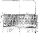
Fig. 1 represents the side partial cross-sectional of first preferred embodiment of the present invention,
Fig. 2 represents the embodiment from Fig. 1 that the A-A direction is observed,
Fig. 3 represents the side partial cross-sectional of another preferred embodiment of the present invention,
Fig. 4 represents the side partial cross-sectional of the 3rd preferred embodiment of the present invention.
According to Fig. 1 and Fig. 2, in an electrolyzer 1, be provided with electrode and comprise anode 2 and the negative electrode of arranging with alternately 3, the electrolyte solution 4 that metal utilization to be produced is located in the electrolyzer 1 in electrolytic process precipitate on the negative electrode 3.In electrolytic process, precipitation has solid 6 on the bottom 5 of electrolyzer, and these solids 6 must be removed from groove 1 at any time.According to the present invention, on the sidewall 8 and 9 of electrolyzer 1, be equipped with and support and control member 10.When separating member 11 is inserted electrolyzer 1 and be introduced in the groove 1, support by described support and control member 10, thereby member 10 forms the path of separating member 11.The bottom of electrolytic tank 12 that will contain solid 6 is made of the structure unit 13 that flexibly connects mutually with the separating member 11 that the rest part of groove 1 separates, in the time of when separating member 11 advances to electrolytic solution bottom 5 near rear wall 7 near, these parts 13 are flex apart member 11 well.
In the embodiment according to Fig. 1 and Fig. 2, separating member 11 is provided with nozzle 14, and liquid or gas are from wherein introducing bottom 12, so that promote the cleaning to solid 6.Solid 6 and the liquid of staying in the bottom 12 are cleared out of electrolyzer 1 with liquid that feeds by nozzle 14 or gas through the outlet 15 that is located on the bottom of electrolytic tank 5.
The embodiment of Fig. 3 is unlike the embodiment of FIG. 1, and wherein, separating member 21 is packed in the electrolyzer 1 hermetically.Therefore, by separating member 21 isolated bottom 22 from electrolyzer, and the space of staying between separating member 21 and the electrolyzer rear wall 7 23 forms the space of base closed together, so that by space 23 liquid in solid 24 and space 22 and 23 is discharged from electrolyzer.
In Fig. 4, a separating member 11 as shown in Figure 1 is placed in the electrolyzer 1, and support and control member 10 are loaded into cell sidewall 8 and 9, so that guarantee that separating member 11 is for example near rear wall 7, insert in the electrolyzer, and near second rear wall 32, from electrolyzer, shift out.
Claims (8)
1. a removal is deposited to the separating member that the solid (6) on electrolyzer (1) bottom separates the bottom of electrolytic tank and the other parts of groove, it is characterized in that, in electrolyzer (1), be equipped with and form separating member (11,21,31) support of path and control member (10), make the separating member (11,21,31) can be by staying at least one rear wall (7 of electrolyzer, 32) and the space between the electrode (2) of close described rear wall is inserted in the electrolyzer (1), and can be from wherein removing.
2. separating member as claimed in claim 1 is characterized in that, separating member (11,21,31) is made by structure unit (13), and they interconnect, so that described parts (13) can be crooked mutually.
3. separating member as claimed in claim 1 or 2 is characterized in that, separated member (11,21,31) separates the space (12) of space bottom of electrolytic tank and is positioned near space (23) formation of the rear wall space of sealing basically.
4. separating member as claimed in claim 3 is characterized in that, (separating member 11,21,31) form sealing, surperficial uniformly in electrolyzer (1).
5. separating member as claimed in claim 1 or 2 is characterized in that, the space (12,23) that separated member (11,21,31) separates links to each other with the space that electrolyzer contains electrolytic solution (4).
6. the described separating member of one of claim as described above is characterized in that, is installed in the separating member (11,21,31) to small part solid brushing apparatus (14), so that supply with washing composition to the bottom (12) of electrolyzer.
7. separating member as claimed in claim 6 is characterized in that, described washing composition is a liquid.
8. separating member as claimed in claim 6 is characterized in that, described washing composition is a gas.
Applications Claiming Priority (2)
| Application Number | Priority Date | Filing Date | Title |
|---|---|---|---|
| FI973565 | 1997-08-29 | ||
| FI973565A FI103673B (en) | 1997-08-29 | 1997-08-29 | A separating member for separating the bottom of the basin from the rest of the basin |
Publications (1)
| Publication Number | Publication Date |
|---|---|
| CN1268983A true CN1268983A (en) | 2000-10-04 |
Family
ID=8549457
Family Applications (1)
| Application Number | Title | Priority Date | Filing Date |
|---|---|---|---|
| CN98808729A Pending CN1268983A (en) | 1997-08-29 | 1998-08-26 | Separating member for separating the tank bottom part from the rest of the tank |
Country Status (18)
| Country | Link |
|---|---|
| US (1) | US6299756B1 (en) |
| EP (1) | EP1025285B1 (en) |
| JP (1) | JP2001515142A (en) |
| KR (1) | KR100567170B1 (en) |
| CN (1) | CN1268983A (en) |
| AT (1) | ATE255174T1 (en) |
| AU (1) | AU735042B2 (en) |
| BG (1) | BG63755B1 (en) |
| BR (1) | BR9811419A (en) |
| CA (1) | CA2301632A1 (en) |
| DE (1) | DE69820104T2 (en) |
| EA (1) | EA001244B1 (en) |
| ES (1) | ES2210804T3 (en) |
| FI (1) | FI103673B (en) |
| PE (1) | PE131199A1 (en) |
| PL (1) | PL191468B1 (en) |
| WO (1) | WO1999011841A1 (en) |
| ZA (1) | ZA987298B (en) |
Cited By (2)
| Publication number | Priority date | Publication date | Assignee | Title |
|---|---|---|---|---|
| CN105696022A (en) * | 2014-11-27 | 2016-06-22 | 江苏永昌新能源科技有限公司 | Auxiliary material fetching apparatus for lithium electrolysis tank |
| CN107398102A (en) * | 2016-03-25 | 2017-11-28 | 何磊 | A kind of sewage pre-treatment device |
Families Citing this family (5)
| Publication number | Priority date | Publication date | Assignee | Title |
|---|---|---|---|---|
| FI103673B (en) * | 1997-08-29 | 1999-08-13 | Outokumpu Oy | A separating member for separating the bottom of the basin from the rest of the basin |
| FI107813B (en) * | 1999-06-17 | 2001-10-15 | Outokumpu Oy | Separation means for separating the bottom portion of a basin from the rest of the basin |
| FI107812B (en) * | 1999-06-17 | 2001-10-15 | Outokumpu Oy | Apparatus for treating solids deposited at the bottom of an electrolysis pool |
| US6274011B1 (en) | 1999-10-08 | 2001-08-14 | Corrosion Technology International, Inc. | Track assembly and container for electrolytic process |
| CN108505072B (en) * | 2018-04-03 | 2020-04-21 | 金川集团股份有限公司 | Annular totally-enclosed buckle type electrodeposition tank |
Family Cites Families (5)
| Publication number | Priority date | Publication date | Assignee | Title |
|---|---|---|---|---|
| US3708415A (en) | 1971-05-24 | 1973-01-02 | W Hubbard | Rapid action electrolytic cell |
| US4214964A (en) * | 1978-03-15 | 1980-07-29 | Cannell John F | Electrolytic process and apparatus for the recovery of metal values |
| IT1111103B (en) * | 1979-02-27 | 1986-01-13 | Montedison Spa | BOTTOM CLEANING EQUIPMENT FOR MERCURY CATHODE AND SIMILAR ELECTROLYTIC CELLS |
| ES2069496B1 (en) * | 1993-08-10 | 1995-11-01 | Asturiana De Zinc Sa | TUB FOR ELECTROLYSIS FACILITIES. |
| FI103673B (en) * | 1997-08-29 | 1999-08-13 | Outokumpu Oy | A separating member for separating the bottom of the basin from the rest of the basin |
-
1997
- 1997-08-29 FI FI973565A patent/FI103673B/en active
-
1998
- 1998-08-25 PE PE1998000780A patent/PE131199A1/en not_active Application Discontinuation
- 1998-08-26 ES ES98941433T patent/ES2210804T3/en not_active Expired - Lifetime
- 1998-08-26 DE DE69820104T patent/DE69820104T2/en not_active Expired - Fee Related
- 1998-08-26 EA EA200000268A patent/EA001244B1/en not_active IP Right Cessation
- 1998-08-26 CN CN98808729A patent/CN1268983A/en active Pending
- 1998-08-26 EP EP98941433A patent/EP1025285B1/en not_active Expired - Lifetime
- 1998-08-26 AT AT98941433T patent/ATE255174T1/en not_active IP Right Cessation
- 1998-08-26 KR KR1020007002170A patent/KR100567170B1/en not_active IP Right Cessation
- 1998-08-26 JP JP2000508839A patent/JP2001515142A/en active Pending
- 1998-08-26 CA CA002301632A patent/CA2301632A1/en not_active Abandoned
- 1998-08-26 AU AU89803/98A patent/AU735042B2/en not_active Ceased
- 1998-08-26 WO PCT/FI1998/000655 patent/WO1999011841A1/en active IP Right Grant
- 1998-08-26 US US09/486,015 patent/US6299756B1/en not_active Expired - Fee Related
- 1998-08-26 BR BR9811419-0A patent/BR9811419A/en not_active Application Discontinuation
- 1998-08-26 PL PL338898A patent/PL191468B1/en unknown
- 1998-08-29 ZA ZA987298A patent/ZA987298B/en unknown
-
2000
- 2000-02-21 BG BG104168A patent/BG63755B1/en unknown
Cited By (2)
| Publication number | Priority date | Publication date | Assignee | Title |
|---|---|---|---|---|
| CN105696022A (en) * | 2014-11-27 | 2016-06-22 | 江苏永昌新能源科技有限公司 | Auxiliary material fetching apparatus for lithium electrolysis tank |
| CN107398102A (en) * | 2016-03-25 | 2017-11-28 | 何磊 | A kind of sewage pre-treatment device |
Also Published As
| Publication number | Publication date |
|---|---|
| US6299756B1 (en) | 2001-10-09 |
| ATE255174T1 (en) | 2003-12-15 |
| JP2001515142A (en) | 2001-09-18 |
| ZA987298B (en) | 1999-02-16 |
| AU735042B2 (en) | 2001-06-28 |
| CA2301632A1 (en) | 1999-03-11 |
| BG63755B1 (en) | 2002-11-29 |
| AU8980398A (en) | 1999-03-22 |
| DE69820104T2 (en) | 2004-05-27 |
| FI973565A (en) | 1999-03-01 |
| EP1025285B1 (en) | 2003-11-26 |
| ES2210804T3 (en) | 2004-07-01 |
| PE131199A1 (en) | 1999-12-21 |
| FI103673B1 (en) | 1999-08-13 |
| FI973565A0 (en) | 1997-08-29 |
| EP1025285A1 (en) | 2000-08-09 |
| BG104168A (en) | 2000-08-31 |
| KR100567170B1 (en) | 2006-04-03 |
| WO1999011841A1 (en) | 1999-03-11 |
| BR9811419A (en) | 2000-08-22 |
| KR20010023524A (en) | 2001-03-26 |
| EA200000268A1 (en) | 2000-08-28 |
| FI103673B (en) | 1999-08-13 |
| PL338898A1 (en) | 2000-11-20 |
| PL191468B1 (en) | 2006-05-31 |
| EA001244B1 (en) | 2000-12-25 |
| DE69820104D1 (en) | 2004-01-08 |
Similar Documents
| Publication | Publication Date | Title |
|---|---|---|
| CA2229661C (en) | Intense yet energy-efficient process for electrowinning of zinc in mobile particle beds | |
| CN1268983A (en) | Separating member for separating the tank bottom part from the rest of the tank | |
| CN102021609B (en) | Electrolytic cell with large contact specific surface area for valuable metal recovery | |
| US4517064A (en) | Electrolytic cell | |
| US4196059A (en) | Method for electrolysis of non-ferrous metal | |
| EP0391028A1 (en) | Continuous silver refining cell | |
| WO2013103407A2 (en) | Continuous recovery system for electrorefiner system | |
| CN1195903C (en) | Arrangement for treating solids settled on bottom of electrolytic tank | |
| US4273640A (en) | Zinc extraction apparatus | |
| AU2011354650B2 (en) | Continuous electrowinning process and system thereof | |
| DE2105038C3 (en) | Method and device for direct electrodeposition of metals | |
| US4183794A (en) | Zinc extraction method | |
| US3808117A (en) | Continuous leaching-precipitation method and apparatus | |
| JPH08176877A (en) | Method for continuously electrolyzing metal and continuous electrolyzer | |
| CA1051820A (en) | Zinc extraction method and apparatus | |
| JPH09263983A (en) | Treatment of iron chloride solution containing nickel and device for executing this method | |
| JP3055821B2 (en) | Method and apparatus for high current density electrolysis | |
| MXPA00002047A (en) | Separating member for separating the tank bottom part from the rest of the tank | |
| JPH08209375A (en) | Silver electrolyzer | |
| JP2003502508A (en) | Separation element that separates the bottom of the cell from the rest of the cell |
Legal Events
| Date | Code | Title | Description |
|---|---|---|---|
| C06 | Publication | ||
| PB01 | Publication | ||
| C10 | Entry into substantive examination | ||
| SE01 | Entry into force of request for substantive examination | ||
| REG | Reference to a national code |
Ref country code: HK Ref legal event code: GR Ref document number: 1051837 Country of ref document: HK |
|
| C02 | Deemed withdrawal of patent application after publication (patent law 2001) | ||
| WD01 | Invention patent application deemed withdrawn after publication |