CN1265183A - Shifting device in variable speed gearbox with pressure regulating valves for working and feed pressure - Google Patents
Shifting device in variable speed gearbox with pressure regulating valves for working and feed pressure Download PDFInfo
- Publication number
- CN1265183A CN1265183A CN98807486A CN98807486A CN1265183A CN 1265183 A CN1265183 A CN 1265183A CN 98807486 A CN98807486 A CN 98807486A CN 98807486 A CN98807486 A CN 98807486A CN 1265183 A CN1265183 A CN 1265183A
- Authority
- CN
- China
- Prior art keywords
- pressure
- pilot pressure
- piston
- valve
- working
- Prior art date
- Legal status (The legal status is an assumption and is not a legal conclusion. Google has not performed a legal analysis and makes no representation as to the accuracy of the status listed.)
- Pending
Links
Images

Classifications
-
- F—MECHANICAL ENGINEERING; LIGHTING; HEATING; WEAPONS; BLASTING
- F16—ENGINEERING ELEMENTS AND UNITS; GENERAL MEASURES FOR PRODUCING AND MAINTAINING EFFECTIVE FUNCTIONING OF MACHINES OR INSTALLATIONS; THERMAL INSULATION IN GENERAL
- F16H—GEARING
- F16H61/00—Control functions within control units of change-speed- or reversing-gearings for conveying rotary motion ; Control of exclusively fluid gearing, friction gearing, gearings with endless flexible members or other particular types of gearing
- F16H61/0021—Generation or control of line pressure
-
- F—MECHANICAL ENGINEERING; LIGHTING; HEATING; WEAPONS; BLASTING
- F16—ENGINEERING ELEMENTS AND UNITS; GENERAL MEASURES FOR PRODUCING AND MAINTAINING EFFECTIVE FUNCTIONING OF MACHINES OR INSTALLATIONS; THERMAL INSULATION IN GENERAL
- F16H—GEARING
- F16H61/00—Control functions within control units of change-speed- or reversing-gearings for conveying rotary motion ; Control of exclusively fluid gearing, friction gearing, gearings with endless flexible members or other particular types of gearing
- F16H61/02—Control functions within control units of change-speed- or reversing-gearings for conveying rotary motion ; Control of exclusively fluid gearing, friction gearing, gearings with endless flexible members or other particular types of gearing characterised by the signals used
- F16H61/0202—Control functions within control units of change-speed- or reversing-gearings for conveying rotary motion ; Control of exclusively fluid gearing, friction gearing, gearings with endless flexible members or other particular types of gearing characterised by the signals used the signals being electric
- F16H61/0251—Elements specially adapted for electric control units, e.g. valves for converting electrical signals to fluid signals
- F16H2061/0253—Details of electro hydraulic valves, e.g. lands, ports, spools or springs
-
- F—MECHANICAL ENGINEERING; LIGHTING; HEATING; WEAPONS; BLASTING
- F16—ENGINEERING ELEMENTS AND UNITS; GENERAL MEASURES FOR PRODUCING AND MAINTAINING EFFECTIVE FUNCTIONING OF MACHINES OR INSTALLATIONS; THERMAL INSULATION IN GENERAL
- F16H—GEARING
- F16H61/00—Control functions within control units of change-speed- or reversing-gearings for conveying rotary motion ; Control of exclusively fluid gearing, friction gearing, gearings with endless flexible members or other particular types of gearing
- F16H61/04—Smoothing ratio shift
- F16H61/0437—Smoothing ratio shift by using electrical signals
Abstract
The invention relates to a shifting device in a variable speed gear box with a frictional connection, whose meshing by means of a hydraulic actuator activates an associated transmission ratio. A control pressure, derived from the working pressure of the actuator, is used to influence the working of a pressure control valve intended for a feed pressure. Said control pressure occurs in a pressure regulating valve which adjusts the working pressure by means of an electronic control unit.
Description
The present invention relates to a kind of by claim 1 shifting of transmission device as described in the preamble.In the gearshift of known the above-mentioned type (DE 4124385 C1), the inlet pressure pressure regulator valve carries out work according to a modulated pressure that depends on load, need an independently adjust system in order to produce modulated pressure, it has improved the cost of liquid electric control and need take valuable installing space at normally used gear shift intralamellar part in transmission case.
By the known a kind of device of DE 4241593 A1, it is used for the vehicle planetary gear-shift transmission automatically from an old so far gear, the sealed connection set of first frictional force (clutch or break) engages by the pressure medium gearshift mechanism of attaching troops to a unit under this gear, be transformed into a new gear, the sealed connection set of second frictional force separates by the working pressure that the pressure medium gearshift mechanism of attaching troops to a unit engages the gearshift mechanism of attaching troops to a unit by cut-out with the sealed connection set of first frictional force under this gear, in this device, used the device of measuring new gear gearshift mechanism working pressure, and when the working pressure of new gear gearshift mechanism meet or exceed one by with reference to amount relatively the back determine important force value the time cut off the working pressure of old gear gearshift mechanism.For the gearshift mechanism that makes current shift also can be thrown off under the situation in gearshift working life of looking after the gear shift travelling comfort and relating to when the gear shift, wherein gear shift travelling comfort may be subjected to the influence of the sliding wear time of the influence of the shifting shock that perhaps takes place and the face length that may be rubbed working life, in this known devices, stipulate, the reference amount is according to the torque load of prime mover and consider that in case of necessity the conversion ratio of fluid dynamic torque converter changes, and important force value relates to of the transferable moment of the sealed connection set of new gear frictional force and the corresponding moment values of moment actual value of loading.In this known devices, the working pressure of gearshift mechanism can be adjusted by the electromagnetic type pressure regulator valve of electronic controller controls by means of one, to inlet pressure relevant with load of pressure regulator valve input.Relevantly generate or produce the problem of this inlet pressure hereof without any explanation.
At last, by the also known a kind of dissimilar device of DE 3630792 A1, depend on that in order to produce one the principal pressure of automobile working state is used to handle the gearshift mechanism of automatic gearbox, it is provided with a table adjustable transfer pump, transfer pump is adjusted principal pressure and has been used a control valve by changing quantity delivered, is used to supply a pump that is the adjustment quantity delivered acts on the transfer pump flow adjuster and adjusts pressure.For guaranteeing principal pressure to be adjusted all the time best corresponding to the automobile working state by means of simple as far as possible device, in this known devices, be designed to, control valve has a generation pump to adjust the adjustment piston of pressure, and the pump that is returned in a side adjusting piston is adjusted the effect of pressure and loaded with the pressure of working state change and the control piston of principal pressure effect by one in reciprocal side.
Purpose of the present invention mainly is the low required expense of inlet pressure maintenance that depends on load for the gearshift of the described type of a kind of preface for generation.The purpose that is proposed reaches by the described feature of claim 1 characteristic in an advantageous manner by the present invention.
Be characterised in that by gearshift of the present invention, only engage a sealed connection set of frictional force and be subjected to the effect of working pressure at each gear.Working pressure is directly by pre-control valve of electromagnetic type and the pressure regulator valve adjustment of attaching troops to a unit.Working pressure can freely be adjusted, and it doesn't matter each other for they.Feature by gearshift of the present invention also is, for example needed six sealed connection sets of frictional force or their control mechanism only infeed working pressure by means of the effect of three the pre-control valves and the pressure regulator valve of attaching troops to a unit thereof altogether in 6 gear gearboxes.Give control mechanism and can be undertaken by guiding valve and two shift valves of manual selection adjusting working pressure, they are handled by a valve position control.In pressing gearshift of the present invention, control mechanism only is subjected to the effect from the pressure of working pressure pressure regulator valve.Be not converted to inlet pressure.
Be characterised in that by gearshift of the present invention that in addition just the working pressure of the sealed connection set of frictional force of delivering power or the control mechanism under it just determines necessary at that time inlet pressure (by the priority control device of claim 2).
By in the gearshift of the present invention, when speed changer is not in the state of transmitted power, determine the basic value (claim 6) of inlet pressure by the valve spring of related pressure regulator valve.
On the one hand claim 3 and on the other hand claim 4,5 respectively have a kind of by the content of the favourable priority control device form of implementation in the gearshift of the present invention as invention.
At reliably working, take this measure by the described measure of claim 7, when the pressure regulator valve of working pressure is stuck in crossover position, avoid the pressure regulator valve of inlet pressure to access too high pressure by gearshift of the present invention.
Further specify the present invention by means of the form of implementation that schematically illustrates in the accompanying drawings below.Accompanying drawing is represented:
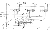
Fig. 1 is expressed as the form of the hydraulic pressure network structure of circuit block diagram and employed valve by first kind of design of gearshift of the present invention.
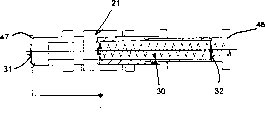
The detail drawing of a pressure regulator valve in Fig. 1 a Fig. 1 gearshift;
Fig. 2 is expressed as the form of the hydraulic pressure network structure of circuit block diagram and employed valve by second kind of design of gearshift of the present invention; And
Fig. 3 is by the valve characteristic figure of the pressure regulator valve of inlet pressure in the gearshift of the present invention.
At first according to Fig. 1, the inlet pressure PV of gearshift produces by the pressure pump 33 by prime mover Continuous Drive, pressure pump is extracted pressure medium incoming pressure pipe 35 out from storage tank 34, and the latter is connected on the pressure regulator valve 7 to 9 that relates separately to a working pressure pA and is connected on the pressure regulator valve 10 of inlet pressure PV.
Pressure regulator valve 7 is according to a pilot pressure pA who depends on the pre-control valve 37 of electromagnetic type of load
*Adjust the working pressure pA of working pressure pipe 11, working pressure pipe 11 is attached troops to a unit in the gearshift mechanism of handling the frictional force sealed connection set relevant with " 4 " with forward gears " 1 " by kickdown valve and picking valve, and pre-control valve 37 can be by electronic controller controls.
Pressure regulator valve 8 is according to a pilot pressure pA who depends on the pre-control valve 38 of electromagnetic type of load
*Adjust the working pressure pA of working pressure pipe 12, working pressure pipe 12 is attached troops to a unit in the gearshift mechanism of handling the frictional force sealed connection set relevant with forward gears " 3 " by kickdown valve and picking valve, and pre-control valve 38 can be by electronic controller controls.
Pressure regulator valve 9 is according to a pilot pressure pA who depends on the pre-control valve 39 of electromagnetic type of load
*Adjust the working pressure pA of working pressure pipe 13, working pressure pipe 13 is attached troops to a unit in the gearshift mechanism of handling the frictional force sealed connection set relevant with forward gear " 2 " and " 5 " and reverse gear " R " by kickdown valve and picking valve, and control valve 39 can be by electronic controller controls in advance.
Pressure regulator valve 7 to 9 also is connected on the pilot pressure pipe 14 or 15 or 16 of telling from their working pressure pipe 11 or 12 or 13, and they are connected with the pressure regulator valve 10 (being 10a among Fig. 2) of inlet pressure pV by priority control device 17 (being 18 among Fig. 2).
Pressure regulator valve 10 (10a) has one to adjust piston 21, and it is divided into two pilot pressure chamber 4 and 25 (Fig. 2 is 26), another pilot pressure chamber 5 and three valve chambers 5,6 and 36 that are in front and back position that are arranged in its end face with valve chamber 24 (being 24a among Fig. 2).Pilot pressure chamber 4 is connected from pressure tube 35 on the pilot pressure pipe 41 that flow controller is told, so adjust piston 21 can be subjected to depending on inlet pressure pV at its related end face with efficient pressure face 31 pilot pressure pV
*Effect, valve spring 30 is then adjusted on the piston 21 along acting in the other direction.Adjusting on the piston 21 one of effect and valve spring 30 pilot pressure in the same way, it based on the effect of priority control device 17 (18) by the working pressure pipe 11 or 12 or 13 derivation that were at that time under the maximum service pressure pA control.
Adjust piston 21 and be in the diameter 47 of the end face 31 in the pilot pressure chamber 4 greater than adjusting the diameter 48 that piston 21 is in the end face 32 in the pilot pressure chamber 25 (26).Because this area difference, adjusting valve 10 (10a) has valve characteristic drawn among Fig. 3, and its feature is, the power pAF32 of the pilot pressure relevant with end face 32 is with the change curve 49 of the Valve travel S power pV than the pilot pressure of being correlated with end face 31
*The change curve 50 of F31 is steeper.Therefore, when one of them pressure regulator valve 7 to 9 may be stuck in crossover position inlet pressure pV be limited in one with maximum value 51 value accordingly, so do not need to establish safety valve.
In thus much illustrated device and the gearshift of design at Fig. 1 and 2 is consistent.
The difference of these two kinds of forms of implementation is the type of their priority control device 17 (18).
In the priority control device 17 of Fig. 1, pressure regulator valve 7 is connected with pilot pressure intervalve 52 by 3/2 logical conversion stop valve 19 in such a way with 8 pilot pressure pipe 14 and 15, that is, make this intervalve 52 all the time be in elevated pressures control under pilot pressure pipe 14 or 15 be communicated with.The pilot pressure pipe 16 of pilot pressure intervalve 52 and pressure regulator valve 9 is connected with the pilot pressure outer pipe 52 that feeds pilot pressure chamber 25 in such a way by means of 3/2 logical conversion stop valve 20, promptly, make pilot pressure chamber 25 all the time be in elevated pressures control pipe 16 or 52 down, that is be in the pilot pressure pipe 14 or 15 or 16 of elevated pressures under controlling and be communicated with.
To change to " 3 " shelves from " 2 " shelves is example explanation working method.
At " 2 " shelves, pre-control valve 39 and the pressure regulator valve 9 that is connected are adjusted the working pressure pA of the affiliated sealed connection set control mechanism of frictional force.The pilot pressure pA16 that is derived by working pressure pA leads to pressure regulator valve 10 through conversion stop valve 20, and determines the size of inlet pressure pV there.In gearshift procedure, the working pressure pA in the working pressure pipe 12 that leads to " 3 " shelves control gear improves with the pressure regulator valve 8 that is connected by pre-control valve 38, and the working pressure pA in " 2 " shelves working pressure pipe 13 reduces by pre-control valve 39.Conversion stop valve 20 conversion when working pressure pipe 12 and 13 internal pressure balances is so the working pressure pA of working pressure pipe 12 acts on the adjustment piston 21 of pressure regulator valve 10 so that adjust in accordance with regulations with valve spring 30 now.
In the priority control device 18 of Fig. 2, the pilot pressure pipe 14 of pressure regulator valve 7 is connected with the pilot pressure chamber 26 of pressure regulator valve 10a, and the pilot pressure pipe 15 of pressure regulator valve 8 is connected with 29 with another pilot pressure chamber 27 of pressure regulator valve 10a respectively with 16.The pilot pressure chamber 26 of pressure regulator valve 10a and 27 spaced-apart by a preferential control piston 23 of can be in valve chamber 24a installing, the latter supports with respect to adjusting piston 21 rigidly by means of depression bar 22 with moving axially. Pilot pressure chamber 27 and 29 spaced-apart by another preferential control piston 28 of can be in valve chamber 24a installing, the latter can be by means of control piston 23 and depression bar 22 equally also rigidly with respect to adjusting piston 21 supportings with moving axially.If pilot pressure pipe 14 is under the pressure maximum, control piston 23 is bearing on the control piston 28 along the direction of leaving from adjustment piston 21 rigidly with respect to valve casing.If pilot pressure pipe 15 is under the pressure maximum, control piston 23 is with respect to adjustment piston 21 rigid supports, and control piston 28 edges are in the other direction with respect to the valve casing rigid support.When pilot pressure pipe 16 is under the maximum pressure, control piston 28 by control piston 23 with respect to adjusting piston 21 rigid supports.Therefore, adjust that piston 21 is adjusted to that pressure regulator valve 7 of maximum service pressure pA all the time or 8 or 9 pilot pressure is handled.
To change to " 3 " shelves from " 2 " shelves is example explanation working method.
At " 2 " shelves, the working pressure pA of working pressure pipe 13 acts on the control piston 28 by the pilot pressure pA16 of the pilot pressure pipe 16 of derivation.Its piston force acts on valve spring 30 via control piston 23 and depression bar 22 and adjusts on the piston 21, with the pilot pressure pV of antagonism by inlet pressure pV derivation
*When gear shift, the working pressure pA of the working pressure pipe 13 of " 2 " shelves improves with the pressure regulator valve 8 that is connected by pre-control valve 38, and the working pressure of the working pressure pipe 13 of " 2 " shelves reduces by pre-control valve 39.In case the working pressure pA of working pressure pipe 12 surpasses the working pressure pA of working pressure pipe 13, control piston 23 and opening in 28 minutes is so the working pressure pA of working pressure pipe 12 acts on the adjustment piston 21 of the pressure regulator valve 10 that is used for inlet pressure pV so that adjust in accordance with regulations with valve spring 30 by means of control piston 23 and depression bar 22 by the pilot pressure pA15 that derives.
Claims (7)
1. the shifting of transmission device that the sealed connection set of frictional force is arranged, make a kind of relevant transmission gear ratio effective by engaging the sealed connection set of frictional force, this gearshift comprises the pressure medium control mechanism and the pressure regulator valve of adjusting this control mechanism working pressure according to electronic controller that are used to handle the sealed connection set of frictional force, the inlet pressure of pressure regulator valve by a pressure regulator valve of attaching troops to a unit according to a ratio adjustment of depending on the control signal of load, it is characterized by: depend on the control signal of load for this, use a pilot pressure (pA14 to pA16) of deriving by working pressure (pA).
2. according to the described gearshift of claim 1, it is characterized by: the pressure regulator valve of inlet pressure (pV) (10,10a) is connected with pilot pressure pipe (14 to 16) by the priority control device (17 or 18) of the mode work of a pressing force balance, and the pilot pressure pipe is carried a pilot pressure (pA14 to pA16) by working pressure (pA) derivation of the control mechanism of at least two that the relate to sealed connection sets of frictional force that are used for respectively handling a transmission gear ratio (gear " 1 " and " 4 " or " 3 " or " 2 " and " 5 " and " R ") of giving a regulation respectively.
3. according to the described gearshift of claim 1, it is characterized by: use one 3/2 logical conversion stop valve (19 and 20) at least for priority control device (17).
4. according to the described gearshift of claim 2, it is characterized by: the adjustment piston (21) of inlet pressure (pV) pressure regulator valve (10a) and preferential control piston (23) are contained in the valve chamber (24a) by tandem arrangement and can move axially relative to one another and with respect to valve chamber (24a), and comprise the first pilot pressure chamber (26) between them; Preferential control piston (23) has sealed the second pilot pressure chamber (27) in valve chamber (24a) with it back to end of adjusting piston (22); Attach troops to a unit and be connected in the pilot pressure pipe (14 and 15) of the sealed connection set of frictional force with one respectively in two pilot pressure chambers (26 and 27); And preferential control piston (23) is along supporting rigidly with respect to adjusting piston towards the direction of adjusting piston (22).
5. according to the described gearshift of claim 4, it is characterized by: the second pilot pressure chamber (27) separates with respect to the 3rd pilot pressure chamber (29) of valve chamber (24a) by second a preferential control piston (28) that is contained in movably vertically in the valve chamber (24a), and the latter is connected with the 3rd pilot pressure pipe (16) of attaching troops to a unit in a sealed connection set of frictional force; And the second preferential control piston (28) is along supporting rigidly with respect to the first preferential control piston (23) towards the direction of adjusting piston (22).
6. according to the described gearshift of one of claim 1 to 5, it is characterized by: the pressure regulator valve of inlet pressure (pV) (10,10a) is subjected to spring mechanism (30) and the influence of the pilot pressure (pA14 to pA16) that is subjected to derive from relevant working pressure (pA) towards the direction that improves inlet pressure (pV), otherwise, be subjected to a pilot pressure (pV who depends on inlet pressure (pV)
*) towards the influence that reduces the direction of inlet pressure (pV).
7. according to the described gearshift of claim 6, it is characterized by: adjust piston (21) at inlet pressure (pV) pressure regulator valve (10,10a) and go up for the pilot pressure (pV that depends on inlet pressure (pV)
*) effective pilot pressure face (31), greater than on this same adjustment piston for the effective pilot pressure face (32) of the pilot pressure (pA14 to pA16) of deriving from relevant working pressure (pA).
Applications Claiming Priority (2)
| Application Number | Priority Date | Filing Date | Title |
|---|---|---|---|
| DE19735820.9 | 1997-08-18 | ||
| DE19735820A DE19735820B4 (en) | 1997-08-18 | 1997-08-18 | Switching device of a change gear with pressure control valves for the working pressure and a supply pressure |
Publications (1)
| Publication Number | Publication Date |
|---|---|
| CN1265183A true CN1265183A (en) | 2000-08-30 |
Family
ID=7839352
Family Applications (1)
| Application Number | Title | Priority Date | Filing Date |
|---|---|---|---|
| CN98807486A Pending CN1265183A (en) | 1997-08-18 | 1998-08-05 | Shifting device in variable speed gearbox with pressure regulating valves for working and feed pressure |
Country Status (8)
| Country | Link |
|---|---|
| US (1) | US6358185B1 (en) |
| EP (1) | EP1003986B1 (en) |
| JP (1) | JP3479911B2 (en) |
| KR (1) | KR20010022867A (en) |
| CN (1) | CN1265183A (en) |
| BR (1) | BR9811211A (en) |
| DE (2) | DE19735820B4 (en) |
| WO (1) | WO1999009338A1 (en) |
Cited By (3)
| Publication number | Priority date | Publication date | Assignee | Title |
|---|---|---|---|---|
| CN102792070A (en) * | 2010-03-11 | 2012-11-21 | Zf腓德烈斯哈芬股份公司 | Hydraulic system for actuating an interlocking switching element of a gearing device |
| CN104358862A (en) * | 2014-10-27 | 2015-02-18 | 哈尔滨东安汽车发动机制造有限公司 | Hydraulic oil circuit for reversing control of automatic transmission |
| CN107810334A (en) * | 2015-06-23 | 2018-03-16 | Zf 腓德烈斯哈芬股份公司 | Valve |
Families Citing this family (3)
| Publication number | Priority date | Publication date | Assignee | Title |
|---|---|---|---|---|
| JP4158033B2 (en) * | 2003-10-24 | 2008-10-01 | 株式会社デンソー | Automatic transmission control device |
| DE102005012590A1 (en) * | 2005-03-18 | 2006-09-21 | Zf Friedrichshafen Ag | Control device for a transmission |
| US7976419B2 (en) * | 2008-12-11 | 2011-07-12 | Ford Global Technologies, Llc | Control of the flow rate in a transmission oil cooler |
Family Cites Families (22)
| Publication number | Priority date | Publication date | Assignee | Title |
|---|---|---|---|---|
| US3641845A (en) * | 1968-07-23 | 1972-02-15 | Toyota Motor Co Ltd | Oil pressure control device for fluid-type automatic transmission |
| JPS4926210B1 (en) * | 1970-01-28 | 1974-07-06 | ||
| US3885476A (en) * | 1971-07-21 | 1975-05-27 | Renault | Pressure regulation control valve for an hydraulic control system of an automatic power transmission |
| DE2537006C2 (en) * | 1975-08-20 | 1983-11-03 | Robert Bosch Gmbh, 7000 Stuttgart | Change gears for automobiles |
| DE2901051A1 (en) * | 1979-01-12 | 1980-07-24 | Bosch Gmbh Robert | HYDRAULIC CONTROL DEVICE FOR THE SWITCHING ELEMENTS OF POWERTRAIN TRANSMISSION |
| JPS5834258A (en) * | 1981-08-19 | 1983-02-28 | Toyota Motor Corp | Switching controller of automatic speed change gear for car |
| US4633737A (en) * | 1982-12-06 | 1987-01-06 | Honda Giken Kogyo Kabushiki Kaisha | Method and apparatus for minimizing pressurized fluid flow in an automatic transmission |
| US4611285A (en) * | 1984-04-05 | 1986-09-09 | Ford Motor Company | Method of controlling automatic transmission shift pressure |
| US4660442A (en) * | 1984-05-14 | 1987-04-28 | Honda Giken Kogyo K.K. | Creep-inhibiting device for an automotive vehicle equipped with an automatic transmission |
| DE3630792C2 (en) * | 1985-09-19 | 1994-10-13 | Volkswagen Ag | Pressure generating device |
| JPS6383442A (en) * | 1986-09-24 | 1988-04-14 | Aisin Seiki Co Ltd | Speed change control device for automatic transmission |
| JP2741023B2 (en) | 1987-04-13 | 1998-04-15 | 富士重工業株式会社 | Hydraulic control device for automatic transmission |
| JPH028551A (en) * | 1988-06-27 | 1990-01-12 | Daikin Mfg Co Ltd | Hydraulic speed change shift control device for automatic transmission |
| DE4036076C2 (en) | 1989-11-15 | 1994-12-01 | Mazda Motor | Hydraulic control for an automatic transmission |
| DE4124385C1 (en) * | 1991-07-23 | 1993-01-07 | Mercedes-Benz Aktiengesellschaft, 7000 Stuttgart, De | |
| FR2691516B1 (en) | 1992-05-19 | 1994-07-01 | Renault | AUTOMATIC TRANSMISSION CONTROL DEVICE WITH STAGE REPORTS. |
| US5443427A (en) | 1992-06-23 | 1995-08-22 | Honda Giken Kogyo Kabushiki Kaisha | Apparatus for controlling automatic transmission |
| DE4241593C2 (en) * | 1992-12-10 | 1996-03-28 | Daimler Benz Ag | Arrangement for automatic reversing of a planetary gear change transmission |
| DE69518249T2 (en) * | 1995-05-06 | 2001-03-08 | Hyundai Motor Co Ltd | AUTOMATIC TRANSMISSION FOR A MOTOR VEHICLE |
| US5913747A (en) * | 1996-06-10 | 1999-06-22 | Hitachi, Ltd. | Hydraulic control apparatus for an automatic transmission of a vehicle |
| JP3496410B2 (en) * | 1996-10-30 | 2004-02-09 | 日産自動車株式会社 | Automatic transmission lock-up line pressure control device |
| JP3026257B2 (en) * | 1998-07-21 | 2000-03-27 | 本田技研工業株式会社 | Control device for hydraulically operated transmission for vehicles |
-
1997
- 1997-08-18 DE DE19735820A patent/DE19735820B4/en not_active Expired - Fee Related
-
1998
- 1998-08-05 KR KR1020007001469A patent/KR20010022867A/en active IP Right Grant
- 1998-08-05 DE DE59802806T patent/DE59802806D1/en not_active Expired - Fee Related
- 1998-08-05 CN CN98807486A patent/CN1265183A/en active Pending
- 1998-08-05 US US09/486,113 patent/US6358185B1/en not_active Expired - Fee Related
- 1998-08-05 WO PCT/EP1998/004870 patent/WO1999009338A1/en active IP Right Grant
- 1998-08-05 JP JP2000509965A patent/JP3479911B2/en not_active Expired - Fee Related
- 1998-08-05 EP EP98943844A patent/EP1003986B1/en not_active Expired - Lifetime
- 1998-08-05 BR BR9811211-2A patent/BR9811211A/en not_active IP Right Cessation
Cited By (4)
| Publication number | Priority date | Publication date | Assignee | Title |
|---|---|---|---|---|
| CN102792070A (en) * | 2010-03-11 | 2012-11-21 | Zf腓德烈斯哈芬股份公司 | Hydraulic system for actuating an interlocking switching element of a gearing device |
| CN102792070B (en) * | 2010-03-11 | 2015-04-22 | Zf腓德烈斯哈芬股份公司 | Hydraulic system for actuating an interlocking switching element of a gearing device |
| CN104358862A (en) * | 2014-10-27 | 2015-02-18 | 哈尔滨东安汽车发动机制造有限公司 | Hydraulic oil circuit for reversing control of automatic transmission |
| CN107810334A (en) * | 2015-06-23 | 2018-03-16 | Zf 腓德烈斯哈芬股份公司 | Valve |
Also Published As
| Publication number | Publication date |
|---|---|
| DE19735820B4 (en) | 2005-08-18 |
| EP1003986B1 (en) | 2002-01-02 |
| KR20010022867A (en) | 2001-03-26 |
| EP1003986A1 (en) | 2000-05-31 |
| BR9811211A (en) | 2000-07-25 |
| JP3479911B2 (en) | 2003-12-15 |
| DE59802806D1 (en) | 2002-02-28 |
| WO1999009338A1 (en) | 1999-02-25 |
| US6358185B1 (en) | 2002-03-19 |
| DE19735820A1 (en) | 1999-03-04 |
| JP2003517536A (en) | 2003-05-27 |
Similar Documents
| Publication | Publication Date | Title |
|---|---|---|
| US5683322A (en) | Continuous hydrostatic-mechanical branch power split transmission particularly for power vehicles | |
| EP0104033B1 (en) | Hydraulic control system for continuously variable transmission | |
| DE102007003923B4 (en) | Method for controlling an automatic transmission of a vehicle | |
| US20050247153A1 (en) | Hydraulic control device for vehicular automatic transmission | |
| CN100578046C (en) | Gear control device | |
| WO2007101467A1 (en) | Method of controlling a hydrostatic drive | |
| CN101907165A (en) | The hydraulic supply unit of automatic transmission | |
| EP0274080A2 (en) | Forward and reverse clutch actuation system for a belt-driven continually variable transmission | |
| US4880090A (en) | Hydraulic controlling system for lockup clutches | |
| DE10303206A1 (en) | Hydrostatic gear for a vehicle, e.g. a construction machine, such as a bucket wheel extractor, is configured so that the intake volume to a hydraulic motor is controlled so that measured and desired vehicle velocities match | |
| CN1329995A (en) | Pipeline pressure control system of automatic speed-transformation | |
| US8849524B2 (en) | Vehicular shift control apparatus | |
| US6350215B1 (en) | Hydraulic control system for pressure control of a CVT variator with limp home mode | |
| CN1265183A (en) | Shifting device in variable speed gearbox with pressure regulating valves for working and feed pressure | |
| US5417626A (en) | Electronic-hydraulic control device for transmission systems of vehicles with automatic gear change | |
| US4712453A (en) | Hydraulic control system for continuously variable transmission | |
| CN103403400B (en) | Hydraulic control device | |
| US4677878A (en) | Hydraulic transmission control system having different state corresponding to different octane fuels | |
| CN109237017B (en) | CVT hydraulic control system | |
| DE4417335A1 (en) | Continuously variable hydrostatic/mechanical split-torque transmission | |
| GB2310012A (en) | Electronic control of gear-engaging hydraulic pressure in an automatic motor vehicle gearbox | |
| DE4339864A1 (en) | Continuously variable hydrostatic-mechanical transmission for automobile | |
| DE19856544A1 (en) | Continuous transmission with hydrostatic power branching with several couplings and control and regulation arrangement | |
| US6030317A (en) | Hydraulic control for operating an automatic gearbox, especially a continuosly variable transmission | |
| US20020173405A1 (en) | Gear actuator for engaging and/or disengaging gears of a transmission |
Legal Events
| Date | Code | Title | Description |
|---|---|---|---|
| C06 | Publication | ||
| PB01 | Publication | ||
| C10 | Entry into substantive examination | ||
| SE01 | Entry into force of request for substantive examination | ||
| C02 | Deemed withdrawal of patent application after publication (patent law 2001) | ||
| WD01 | Invention patent application deemed withdrawn after publication |