CN1264656C - Electric power tool - Google Patents
Electric power tool Download PDFInfo
- Publication number
- CN1264656C CN1264656C CNB031586783A CN03158678A CN1264656C CN 1264656 C CN1264656 C CN 1264656C CN B031586783 A CNB031586783 A CN B031586783A CN 03158678 A CN03158678 A CN 03158678A CN 1264656 C CN1264656 C CN 1264656C
- Authority
- CN
- China
- Prior art keywords
- fan
- motor
- drive transmission
- rotation drive
- transmission member
- Prior art date
- Legal status (The legal status is an assumption and is not a legal conclusion. Google has not performed a legal analysis and makes no representation as to the accuracy of the status listed.)
- Expired - Fee Related
Links
Images


Classifications
-
- H—ELECTRICITY
- H02—GENERATION; CONVERSION OR DISTRIBUTION OF ELECTRIC POWER
- H02K—DYNAMO-ELECTRIC MACHINES
- H02K7/00—Arrangements for handling mechanical energy structurally associated with dynamo-electric machines, e.g. structural association with mechanical driving motors or auxiliary dynamo-electric machines
- H02K7/14—Structural association with mechanical loads, e.g. with hand-held machine tools or fans
- H02K7/145—Hand-held machine tool
-
- B—PERFORMING OPERATIONS; TRANSPORTING
- B25—HAND TOOLS; PORTABLE POWER-DRIVEN TOOLS; MANIPULATORS
- B25F—COMBINATION OR MULTI-PURPOSE TOOLS NOT OTHERWISE PROVIDED FOR; DETAILS OR COMPONENTS OF PORTABLE POWER-DRIVEN TOOLS NOT PARTICULARLY RELATED TO THE OPERATIONS PERFORMED AND NOT OTHERWISE PROVIDED FOR
- B25F5/00—Details or components of portable power-driven tools not particularly related to the operations performed and not otherwise provided for
- B25F5/008—Cooling means
-
- H—ELECTRICITY
- H02—GENERATION; CONVERSION OR DISTRIBUTION OF ELECTRIC POWER
- H02K—DYNAMO-ELECTRIC MACHINES
- H02K7/00—Arrangements for handling mechanical energy structurally associated with dynamo-electric machines, e.g. structural association with mechanical driving motors or auxiliary dynamo-electric machines
- H02K7/10—Structural association with clutches, brakes, gears, pulleys or mechanical starters
- H02K7/116—Structural association with clutches, brakes, gears, pulleys or mechanical starters with gears
-
- H—ELECTRICITY
- H02—GENERATION; CONVERSION OR DISTRIBUTION OF ELECTRIC POWER
- H02K—DYNAMO-ELECTRIC MACHINES
- H02K9/00—Arrangements for cooling or ventilating
- H02K9/02—Arrangements for cooling or ventilating by ambient air flowing through the machine
- H02K9/04—Arrangements for cooling or ventilating by ambient air flowing through the machine having means for generating a flow of cooling medium
- H02K9/06—Arrangements for cooling or ventilating by ambient air flowing through the machine having means for generating a flow of cooling medium with fans or impellers driven by the machine shaft
Abstract
The rotation drive transmission block 5 including an decelerator is provided between a chuck 2 at the tip of which a tool is mounted, and a motor 4 built in a housing 3. Outdoor air introduced from inlets 6 formed in the housing 3 by movement of a built-in fan 8 cools the the motor 4 and the rotation drive transmission block 5. Outlets 7 for discharging the outdoor air after cooling are formed in the housing 3. A power tool is configured as above. The fan 8 is arranged between the motor 4 and the rotation drive transmission block 5. The fan 8 is constituted so as to suction air from two directions, namely a direction of the motor, and that of the rotation drive transmission block. The inlets 6a and 6b are arranged on a motor side and a rotation drive transmission block 5 side. The outlets 7 are formed near the fan. To efficiently cool a motor and a rotation drive transmission block with a fan of simple structure, and to save on a space, while reducing cost.
Description
Technical field
The present invention relates to a kind of electric tool, specifically, relate to a kind of electric tool that utilizes a fan that the high motor of the heat generation in the electric tool and rotation drive transmission member are cooled off effectively.
Background technology
Usually, in electric tool, fan is installed on the output shaft of motor, motor upstream side at shell is provided with air entry, in the motor downstream exhaust outlet is set, and form cooling duct in the enclosure by motor, utilization is accompanied by the fan rotation that motor drives, and produces air stream in the cooling duct, and the heating of motor is cooled off.
But, in the cooling structure of above-mentioned electric tool, can not cool off rotation at a high speed and the heating that produces the rotation drive transmission member of frictional heat, and the durability of rotation drive transmission member is reduced.
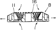
Therefore, as shown in figure 14, existing electric tool forms air entry 6 and exhaust outlet 7 on shell 3, around the rotation drive transmission member 5 or near be provided with ventilating duct 20, utilize the rotation of the cooling fan 19 on the output shaft 15 be installed in motor 4, the air conductance behind the cooling motor 4 is gone in the ventilating duct 20, by rotation drive transmission member 5 is forced cooling, dispel the heat, can improve the durability (for example, with reference to patent document 1) of rotation drive transmission member 5.
In addition, as shown in figure 15, as other device, except that adding cooling fan 19, also be included in air entry 6 and exhaust outlet 7 are set on the shell 3, front end at shell 3 is provided with chuck 2, supporting on this chuck 2 and the revolvable rotating shaft 21, the fan 22 of cooling usefulness is installed, rotation drive transmission member 5 is forced cooling, distribute heat improves the durability (for example, with reference to patent document 2) of rotating drive transmission member 5.
But, in above-mentioned patent document 1 disclosed device, the cooling air that the heating of rotation drive transmission member 5 is cooled off is motor 4 to be cooled off also thereby just arriving at rotation drive transmission member 5 after being heated, therefore greatly reducing the cooling effectiveness of rotation drive transmission member 5.
In addition, in above-mentioned patent document 2 disclosed devices, must be provided for two cooling fans 19,22 of cooling motor and cooling rotation drive transmission member, complex structure, cost improves, and, owing to need necessary space, electric tool is increased.
Wherein, patent document 1: the spy opens flat 9-11158 (referring to illustrations 14).
Patent document 2: the spy opens flat 9-11157 (referring to illustrations 15)
Summary of the invention
The present invention makes in view of the above problems, the purpose of this invention is to provide a kind of when motor is cooled off with the rotation drive transmission member, can utilize fan simple in structure efficiently to cool off, reduce cost, and can save the electric tool in space, the size of caloric value realizes the adjustment to distinguished and admirable size during wherein respectively according to the motor of electric tool and the work of rotation drive transmission member.
The technical scheme that realizes the object of the invention is:
A kind of electric tool, be the chuck of front end erecting tools and be built between the interior motor of shell to be provided with the rotation drive transmission member that comprises reductor, running by built-in fans, and import extraneous gas by the air entry that is formed on the shell, motor and rotation drive transmission member are cooled off, and the exhaust outlet that will discharge cooled extraneous gas is formed on the shell, between motor and rotation drive transmission member, dispose fan, fan is air-breathing from motor direction and rotation drive transmission member direction two directions, and put air entry and air entry is set in rotation drive transmission member side at motor Ce Let, described exhaust outlet is arranged near the fan, it is characterized in that, fan is arranged on the substrate, substrate is provided with through hole, wherein the blade face of the air-breathing usefulness of fan to the through hole of motor one side and substrate towards rotation drive transmission member one side, thereby make the inspiratory force of the inspiratory force of motor-side greater than the rotary driving part side.
In the 1st invention, a kind of electric tool, be the chuck 2 of front end erecting tools and be built between the motor 4 in the shell 3 to be provided with the rotation drive transmission member 5 that comprises reductor, running by built-in fans 8, and import extraneous gas by the air entry 6 that is formed on the shell 3, motor 2 and rotation drive transmission member 5 are cooled off, and the exhaust outlet 7 that will discharge cooled extraneous gas is formed on the shell 3, it is characterized in that: between motor 4 and rotation drive transmission member 5, dispose fan 8, fan 8 is air-breathing from two directions of motor direction and rotation drive transmission member direction, and air entry 6a is set in motor-side and rotation drive transmission member side, 6b is provided with exhaust outlet 7 near fan 8.
According to this structure, utilize the running of fan 8, can be air-breathing from two directions of the air entry 6a, the 6b that are formed on motor-side and rotation drive transmission member side, can cool off separately respectively motor 4 and rotation drive transmission member 5, implement cooling and heated extraneous gas can be discharged by near the exhaust outlets 7 that are formed on the fan 8, use a fan 8, just can improve the cooling effectiveness of motor 4 and rotation drive transmission member 5, simplified structure reduces cost, and saves the space.
In the 2nd invention, it is characterized in that: fan 8 is big in the inspiratory force of rotation drive transmission member side at the inspiratory force ratio of motor-side.According to this formation, use a fan 8, just can compare, import more extraneous gas with rotation drive transmission member side in motor-side, can contrast the high motor 4 of rotation drive transmission member 5 caloric values effectively cools off, in view of the above, fan 8 miniaturizations can be made, the load of motor 4 can be reduced.
Simultaneously, the identical situation of caloric value of motor 4 sides and the generation of rotation drive transmission member 5 sides seldom appears, and the rising more of the power of electric tool self, it is uneven that both caloric values become more.In this case, if when adopting the radial fan 8X of existing normal use as shown in figure 16, because the soakage of fan both sides is identical, must cooperate the many sides (motor 4) of caloric value to set the fan mode, and consider from the low side of caloric value (rotation drive transmission member 5), fan maximizes, and it is big that the load of motor 4 becomes.
But, in fan 8, the setting or the setting of the area of the air entry 6b of air entry 6a by carrying out motor-side and rotation drive transmission member side from each air entry 6a, 6b to the resistance of each air supply path of fan 8, and can realize obtaining structure corresponding to the inspiratory capacity of caloric value.
In the 3rd invention, it is characterized in that: fan 8 substrates 9 are provided with through hole 10, are formed with the blade 11 of air-breathing usefulness in motor-side.If adopt this structure, then self-evident, having an air-breathing side with blade 11 can be air-breathing from opposition side through the through hole 10 of substrate, can make a side draught tolerance become big with blade 11, thereby, by in the face of blade 11 fan 8 being set, rotate the broad-minded structure of drive transmission member side draught and obtain the motor-side ratio easily in motor-side.
In the 4th invention, it is characterized in that: at pivot be with fan 8 center the concentric circles equal intervals a plurality of through holes 10 are set.According to this structure, can improve the spin balancing of fan 8, can realize rotating stably.
In the 5th invention, it is characterized in that: the introduction part 13 that on the enhancing wall 12 between the through hole 10,10, is formed with taper.According to this structure, can improve from the gettering efficiency of through hole 10, reduce the load of motor 4.
In the 6th invention, it is characterized in that: fan 8 is formed with the blade 11,14 of air-breathing usefulness in substrate 9 both sides.According to this structure, can be air-breathing fully from the both sides of fan 8.
In the 7th invention, it is characterized in that: connect the cylindrical shell of fixing on the axle 15 be inserted in motor 4 16 being formed with on the fan 8, the external diameter of described cylindrical shell 16 diminishes along the direction of leaving substrate from substrate 9 beginnings of fan 8.According to this structure, the air that is produced by the air-breathing of fan 8 is flowed steadily, improve gettering efficiency, reduce the load of motor 4.
In the 8th invention, it is characterized in that: form substrate 9 by the good conductor of heat at least in the fan 8.According to this structure, utilize the axle 15 of motor 4 that the heating of motor 4 with rotation drive transmission member 5 is sent on the substrate 9 of fan 8.Can improve cooling effectiveness by the surperficial distribute heat of the substrate 9 of hot good conductor.
In the 9th invention, it is characterized in that: the cover 17 with the good conductor of heat coats rotation drive transmission member 5, in the passage of the cooling air of the fan 8 of the outside of cover 17, forms heat radiation projection 18.According to this structure, can increase from the heat dissipation capacity on cover 17 surfaces that coat rotation drive transmission member 5, thereby, can reduce the inspiratory capacity of rotation drive transmission member side, and reduce the load of motor 4.
Description of drawings
Fig. 1 is the front view of expression one embodiment of the invention.
Fig. 2 is the front view with shell partly cut-away of the embodiment of the invention.
Fig. 3 is the cutaway view of the internal structure of the expression embodiment of the invention.
Fig. 4 is the fan of the expression embodiment of the invention and the stereogram of cowling panel.
Fig. 5 is the fan of the expression embodiment of the invention and the exploded perspective view of cowling panel.
Fig. 6 (a) is the fan of the expression embodiment of the invention and the side view of cowling panel, (b) is the front view of this fan of expression and cowling panel.
Fig. 7 is the stereogram of the fan of the expression embodiment of the invention.
Fig. 8 is the cutaway view of the fan of the expression embodiment of the invention.
Fig. 9 is the side view of the fan of the expression embodiment of the invention.
Figure 10 is the partial sectional view of the fan of the expression embodiment of the invention.
Figure 11 (a) is the front view of the fan of embodiments of the invention, (b) is the side view of this fan, (c) is the rearview of this fan.
Figure 12 (a) is the front view of another embodiment of expression fan of the present invention, (b) is the side view of this fan, (c) is the rearview of this fan.
Figure 13 (a) is the front view of an embodiment again of expression fan of the present invention, (b) is the side view of this fan, (c) is the rearview of this fan.
Figure 14 is the front view of major part of the partly cut-away of existing example.
Figure 15 is the front view of major part of the partly cut-away of another existing example of expression.
Figure 16 (a) is the front view of the fan of the existing example of expression, (b) is the side view of this fan of expression.
Among the figure: the 1-instrument, the 2-chuck, the 3-shell, the 4-motor, 5-rotates drive transmission member, 6-air entry, 7-exhaust outlet, 8-fan.
The specific embodiment
Below, embodiments of the invention are described.Fig. 1 is a front view.Fig. 2 is the front view with shell partly cut-away.Fig. 3 is the cutaway view of expression internal structure.
Electric tool A, rear, inside at shell 3 is built-in with motor 4, dispose rotation drive transmission member 5 in the place ahead of motor 4, it includes the reductor of the output that can transmit motor 4, the leading section of shell 3 in the place ahead of this rotation drive transmission member 5, be provided with the chuck 2 of erecting tools, the rotary driving force of the drive transmission member of spinning in the future 5 is delivered to the output rotating shaft 23 of chuck 2, and this electric tool A is the electric tool such as hammer drill, auger boring instrument etc.
Be built in the motor 4 in the electric tool A, cause heating by power consumption, in rotation drive transmission member 5, also cause heating by friction between the mechanical organ etc., thereby on the output shaft 15 of the motor 4 between motor 4 and the rotation drive transmission member 5, fan 8 is installed, be used for the heating of motor 4 and rotation drive transmission member 5 is cooled off.
In electric tool A of the present invention, utilize the heating of 8 pairs of high febrifacient motors 4 of a fan and rotation drive transmission member 5 to cool off effectively.Hereinafter this is described in detail.
If employing said structure, running according to fan 8, can carry out air-breathing in two directions of the air entry 6a, the 6b that are formed at motor-side and rotation drive transmission member side, can realize respectively separately motor 4 and rotation drive transmission member 5 being cooled off, cool off and heated extraneous gas can utilize near the exhaust outlets 7 that are formed on the fan 8 to discharge.Like this, though use a fan 8, can improve the cooling effectiveness of motor 4 and rotation drive transmission member 5, simplified structure reduces cost, and saves the space.
As Fig. 4 and shown in Figure 5, make the ring-type cowling panel 25 that is formed with outlet 24 around fan 8.The exhaust wind that utilizes 25 pairs of fans 8 of cowling panel to be produced carries out rectification, and air is successfully guided exhaust outlet 7 to shell 3 by the exhaust outlet 24 of cowling panel 25, increases the air quantity of discharging from shell 3, improves cooling capacity.Wherein, can carry out various changes to the mode of cowling panel 25.
As Fig. 6 (b), Fig. 7 and shown in Figure 10, on fan 8, be provided with the blade 11 of air-breathing usefulness by the one side of fan 8, on the substrate 9 of fan 8, through hole 10 is set, and has an air-breathing side with blade 11 much less, can be air-breathing from opposition side through the through hole 10 of substrate, side draught tolerance with blade 11 is increased, thereby,, rotate the broad-minded structure of drive transmission member side draught and obtain the motor-side ratio easily by in the face of blade 11 fan 8 being set in motor-side.
Like this, fan 8, the inspiratory force of motor-side is bigger than the inspiratory force of rotation drive transmission member side, though use a fan 8, can make extraneous gas many but compare, compare and to cool off the high motor 4 of caloric value effectively with rotation drive transmission member 5, therefore from the amount that motor-side imports with rotation drive transmission member side, fan can miniaturization, and can reduce the load of motor 4.
And, at pivot be with fan 8 center the concentric circles equal intervals a plurality of through holes 10 are set, can improve the spin balancing of fan 8, obtain rotation stably.
And, on the reinforced wall 12 between the through hole on the substrate 9 10,10, form taper introduction part 13, can improve the gettering efficiency of through hole 10, reduce the load of motor 4.
But, in fan 8, by carrying out, and can realize obtaining structure corresponding to the inspiratory capacity of caloric value to the setting of the aperture area of the air entry 6b of the air entry 6a of motor-side and rotation drive transmission member side or to setting etc. from each air entry 6a, 6b to the flow path resistance of the air supply path of fan 8.
Figure 12 represents another embodiment, but the basic structure of present embodiment is same as the previously described embodiments, adopts identical symbol for same section, and the Therefore, omited is to its explanation.
In the present embodiment, in fan 8, the both sides of the substrate 9 of fan 8 are provided with blade 11,14, obtain inspiratory force with the blade 11,14 that utilizes substrate 9 both sides.At this moment, for example, the quantity of the blade 11 of motor-side is more than the quantity of the blade 14 of rotation drive transmission member side, so that the inspiratory capacity of motor-side is bigger than the inspiratory capacity of rotation drive transmission member side, be accompanied by the caloric value of motor-side and rotation drive transmission member side, guarantee to cool off balance.
Figure 13 represents an embodiment again, but the basic structure of present embodiment is same as the previously described embodiments, adopts identical symbol for same section, omits its explanation.
In the present embodiment, inequality by the blade height H1, the H2 that make the blade 11,14 that is arranged on substrate 9 both sides, and make the inspiratory capacity difference.That is to say, the height H 1 of blade 11 that makes motor-side is than height H 2 height of the blade 14 of rotation drive transmission member side, make the inspiratory capacity of motor-side bigger, to guarantee the cooling balance of motor-side and rotation drive transmission member side than the inspiratory capacity of rotation drive transmission member side.
In Figure 11~embodiment illustrated in fig. 13, connect the cylindrical shell of fixing on the axle 15 be inserted in motor 4 16 being formed with on the fan 8, the external diameter of cylindrical shell 16 diminishes more away from the substrate 9 of fan 8 more, the air that can make the air-breathing of fan 8 and produce flows steadily, improve gettering efficiency, reduce the load of motor 4.
And, in the fan 8 in above embodiment, form the substrate 9 and the cylindrical shell 16 of fan 8 by the good conductor of the heat of aluminium etc., utilize the axle 15 of motor 4 that the heating of motor 4 with rotation drive transmission member 5 is sent on the cylindrical shell 16, further, by the substrate 9 to fan 8 conduct heat, by surface radiating, and can improve cooling effectiveness.
In addition, on the rotation drive transmission member 5 in above embodiment, cover 17 with the good conductor of heat coats rotation drive transmission member 5, on the passage of the cooling air of the fan 8 of cover 17 outside, form heat radiation projection 18, can increase from the heat dissipation capacity on cover 17 surfaces that coat rotation drive transmission member 5, thereby, can reduce the inspiratory capacity of rotation drive transmission member side, to reduce the load of motor 4.
(invention effect)
In the 1st invention, utilize the rotation of fan, can carry out air-breathingly from being formed at motor-side and air entry two directions of rotation drive transmission member side, can realize separately motor and rotation drive transmission member being cooled off respectively.Realize cooling and heated extraneous gas can be discharged by near the exhaust outlet that is formed on the fan, uses a fan, can improve motor and rotate the cooling effectiveness of drive transmission member, the advantage that has simplified structure, reduces cost and save the space.
In the 2nd invention, use a fan, compare with rotation drive transmission member side, can import more extraneous gas in motor-side, can contrast the high motor of rotation drive transmission member caloric value effectively cools off, the fan miniaturization can be made thereby have, and the advantage of the load of motor can be reduced.
In the 3rd invention, self-evident, having an air-breathing side with blade 11 can be air-breathing from opposition side through the through hole 10 of substrate, can make a side draught large-minded with blade 11, thereby, by the fan 8 of subtend blade 11 is set in motor-side, rotate the broad-minded structure of drive transmission member side draught and obtain the motor-side ratio easily.
In the 4th invention, have the spin balancing that can improve fan, and can realize the advantage of rotating stably.
In the 5th invention, have the gettering efficiency that can improve, and can reduce the advantage of the load of motor 4 from through hole.
In the 6th invention, have and to carry out air-breathing advantage from the fan both sides fully.
In the 7th invention, the air-breathing air that produces because of fan is flowed steadily, have the advantage that improves gettering efficiency and reduce the load of motor.
In the 8th invention, utilize axle that the heating of motor and rotation drive transmission member is sent on the substrate of fan, can have the advantage that can improve cooling effectiveness by the surface radiating of the substrate of the good conductor of heat.
In the 9th invention, can increase from the heat dissipation capacity on the cover surface that covers the rotation drive transmission member, thereby, have inspiratory capacity that can reduce rotation drive transmission member side and the advantage that can reduce the load of motor.
Claims (7)
1. an electric tool (A), be the chuck (2) of front end erecting tools and be built between the interior motor (4) of shell (3) to be provided with the rotation drive transmission member (5) that comprises reductor, running by built-in fans (8), and import extraneous gas by the air entry that is formed on the shell (3), motor (4) and rotation drive transmission member (5) are cooled off, and the exhaust outlet (7) that will discharge cooled extraneous gas is formed on the shell (3), between motor (4) and rotation drive transmission member (5), dispose fan (8), fan (8) is air-breathing from motor (4) direction and rotation drive transmission member (5) direction two directions, and at motor (4) Ce Let put air entry (6a) and in rotation drive transmission member (5) side air entry (6b) are set, described exhaust outlet (7) is arranged near the fan (8), it is characterized in that, fan (8) is arranged on the substrate (9), substrate (9) is provided with through hole (10), wherein the blade (11) of the air-breathing usefulness of fan (8) towards the through hole (10) of motor (4) one sides and substrate (9) towards rotation drive transmission member (5) one sides, thereby make the inspiratory force of the inspiratory force of motor (4) side greater than rotary driving part (5) side.
2. electric tool (A) according to claim 1 is characterized in that: at pivot be with fan (8) center the concentric circles equal intervals be provided with a plurality of through holes (10).
3. as electric tool (A) as described in the claim 2, it is characterized in that: on the enhancing wall between the through hole (10), be formed with taper introduction part (13).
4. electric tool (A) according to claim 1, it is characterized in that: fan (8) also is formed with the blade (14) of air-breathing usefulness at the opposite side of substrate (9).
5. electric tool (A) according to claim 1, it is characterized in that: connect the cylindrical shell of fixing on the axle (15) be inserted in motor (4) (16) being formed with on the fan (8), the external diameter of cylindrical shell (16) diminishes along the direction away from substrate (9) from the substrate (9) of fan (8).
6. electric tool (A) according to claim 1 is characterized in that: form substrate (9) by the good conductor of heat at least in fan (8).
7. electric tool (A) according to claim 1 is characterized in that: the cover (17) with the good conductor of heat coats rotation drive transmission member (5), and in the passage of the cooling air that is produced by fan (8) of the outside of cover (17), is formed with the heat radiation projection.
Applications Claiming Priority (2)
| Application Number | Priority Date | Filing Date | Title |
|---|---|---|---|
| JP2002264433 | 2002-09-10 | ||
| JP2002264433A JP4075540B2 (en) | 2002-09-10 | 2002-09-10 | Electric tool |
Publications (2)
| Publication Number | Publication Date |
|---|---|
| CN1494994A CN1494994A (en) | 2004-05-12 |
| CN1264656C true CN1264656C (en) | 2006-07-19 |
Family
ID=31884759
Family Applications (1)
| Application Number | Title | Priority Date | Filing Date |
|---|---|---|---|
| CNB031586783A Expired - Fee Related CN1264656C (en) | 2002-09-10 | 2003-09-09 | Electric power tool |
Country Status (6)
| Country | Link |
|---|---|
| US (1) | US6971456B2 (en) |
| EP (1) | EP1398864B1 (en) |
| JP (1) | JP4075540B2 (en) |
| CN (1) | CN1264656C (en) |
| AT (1) | ATE413715T1 (en) |
| DE (1) | DE60324512D1 (en) |
Families Citing this family (60)
| Publication number | Priority date | Publication date | Assignee | Title |
|---|---|---|---|---|
| JP4329369B2 (en) | 2003-03-20 | 2009-09-09 | パナソニック電工株式会社 | Power tool usage support method and apparatus |
| JP4557555B2 (en) * | 2004-01-08 | 2010-10-06 | 株式会社マキタ | Electric tool |
| CN2688454Y (en) * | 2004-03-25 | 2005-03-30 | 苏州宝时得电动工具有限公司 | Cooling structure of electric tool |
| DE102004031042B4 (en) * | 2004-06-25 | 2015-08-20 | Andreas Stihl Ag & Co. Kg | implement |
| DE102004055268A1 (en) * | 2004-11-17 | 2006-05-18 | Robert Bosch Gmbh | Hand tool |
| DE102004058696A1 (en) * | 2004-12-06 | 2006-06-08 | Hilti Ag | Electric power tool |
| ATE396841T1 (en) * | 2004-12-23 | 2008-06-15 | Black & Decker Inc | POWER TOOL HOUSING |
| EP1674213B1 (en) * | 2004-12-23 | 2008-10-01 | BLACK & DECKER INC. | Power tool cooling |
| GB0428210D0 (en) * | 2004-12-23 | 2005-01-26 | Black & Decker Inc | Mode change mechanism |
| JP4791771B2 (en) * | 2005-07-01 | 2011-10-12 | 日本電産テクノモータホールディングス株式会社 | Electric tool |
| JP2007160420A (en) * | 2005-12-09 | 2007-06-28 | Matsushita Electric Works Ltd | Impact tool |
| US20090065228A1 (en) * | 2005-12-09 | 2009-03-12 | Koichi Hashimoto | Power impact tool |
| JP2007223009A (en) * | 2006-02-24 | 2007-09-06 | Ryobi Ltd | Centrifugal fan for power tool and power tool provided with the same |
| JP2007320004A (en) * | 2006-06-02 | 2007-12-13 | Zenoah:Kk | Portable work machine |
| CN2936610Y (en) * | 2006-08-09 | 2007-08-22 | 南京德朔实业有限公司 | Hand-held electric tool |
| US7988538B2 (en) | 2006-10-13 | 2011-08-02 | Black & Decker Inc. | Large angle grinder |
| JP2008173716A (en) * | 2007-01-18 | 2008-07-31 | Max Co Ltd | Electric power tool having brushless motor |
| JP5013314B2 (en) | 2007-06-18 | 2012-08-29 | 日立工機株式会社 | Electric tool |
| JP4609489B2 (en) * | 2007-12-25 | 2011-01-12 | パナソニック電工株式会社 | Electric tool |
| CN101543967B (en) | 2008-03-28 | 2011-12-28 | 德昌电机(深圳)有限公司 | Electric drill with cooling system |
| JP4605242B2 (en) * | 2008-04-10 | 2011-01-05 | パナソニック電工株式会社 | Electric tool |
| DE102008001258A1 (en) * | 2008-04-18 | 2009-10-22 | Robert Bosch Gmbh | Machine tool with electric drive motor |
| JP5477759B2 (en) * | 2008-07-30 | 2014-04-23 | 日立工機株式会社 | Electric tool |
| JP5522504B2 (en) * | 2008-09-29 | 2014-06-18 | 日立工機株式会社 | Electric tool |
| DE102009012177A1 (en) * | 2009-02-27 | 2010-09-02 | Andreas Stihl Ag & Co. Kg | Battery operated, handheld electrical appliance |
| US20100232894A1 (en) * | 2009-03-16 | 2010-09-16 | The Boeing Company | Adaptor with Interchangeable Load Sensing Elements |
| JP5397606B2 (en) * | 2009-06-24 | 2014-01-22 | 日立工機株式会社 | Oil pulse tool |
| DE102010031274B4 (en) * | 2009-12-18 | 2023-06-22 | Robert Bosch Gmbh | Hand tool with gear cooling |
| US8636081B2 (en) * | 2011-12-15 | 2014-01-28 | Milwaukee Electric Tool Corporation | Rotary hammer |
| US10056806B2 (en) * | 2010-06-14 | 2018-08-21 | Black & Decker Inc. | Stator assembly for a brushless motor in a power tool |
| DE102010030376A1 (en) * | 2010-06-23 | 2011-12-29 | Robert Bosch Gmbh | Hand tool |
| EP2465647A3 (en) * | 2010-12-20 | 2013-01-16 | HILTI Aktiengesellschaft | Hand tool machine with air circulation element |
| JP5836621B2 (en) * | 2011-03-31 | 2015-12-24 | 株式会社マキタ | Power tools |
| JP5728303B2 (en) * | 2011-06-15 | 2015-06-03 | 株式会社マキタ | Impact tool |
| CN102383908B (en) * | 2011-10-27 | 2013-02-13 | 山东华盛农业药械有限责任公司 | Cooling device of engine of blowing and sucking blade machine |
| US20130299207A1 (en) * | 2012-05-10 | 2013-11-14 | Black & Decker, Inc. | Power tool cooling |
| FR2992539B1 (en) * | 2012-06-29 | 2015-05-29 | Seb Sa | VENTILATION SHEATH OF AN ELECTRICAL APPLIANCE |
| US9289878B2 (en) * | 2013-08-30 | 2016-03-22 | Ingersoll-Rand Company | Grinders with friction drives |
| JP6127840B2 (en) * | 2013-09-02 | 2017-05-17 | 日立工機株式会社 | Electric tool |
| GB201413008D0 (en) | 2014-07-23 | 2014-09-03 | Black & Decker Inc | A range of power tools |
| US10350743B2 (en) * | 2015-09-08 | 2019-07-16 | Chervon (Hk) Limited | Handheld electric tool |
| AU201615156S (en) | 2016-03-17 | 2016-12-09 | Tti Macao Commercial Offshore Ltd | Battery pack |
| AU201615153S (en) | 2016-03-17 | 2016-12-09 | Tti Macao Commercial Offshore Ltd | Battery pack |
| AU201615158S (en) | 2016-03-17 | 2016-12-09 | Tti Macao Commercial Offshore Ltd | Battery pack |
| CN107355528A (en) * | 2016-05-10 | 2017-11-17 | 德昌电机(深圳)有限公司 | A kind of electric tool of drive device and the application drive device |
| CN105958728A (en) * | 2016-06-16 | 2016-09-21 | 溧水县得瑞微型电机厂 | Self-cooling rotary motor |
| GB201610953D0 (en) * | 2016-06-23 | 2016-08-10 | Black & Decker Inc | Motor end cap |
| CN109328123B (en) * | 2016-06-30 | 2022-04-29 | 工机控股株式会社 | Electric tool |
| JP2018012154A (en) * | 2016-07-20 | 2018-01-25 | 株式会社マキタ | Electric work machine |
| USD853813S1 (en) * | 2017-01-17 | 2019-07-16 | Tti (Macao Commercial Offshore) Limited | Power tool |
| USD926674S1 (en) | 2017-01-17 | 2021-08-03 | Tti (Macao Commercial Offshore) Limited | Battery pack with communication terminal |
| TWD200631S (en) | 2017-01-17 | 2019-11-01 | 澳門商創科 澳門離岸商業服&#x | Battery pack |
| USD853216S1 (en) | 2017-01-17 | 2019-07-09 | Tti (Macao Commercial Offshore) Limited | Power tool |
| US20180331597A1 (en) * | 2017-05-15 | 2018-11-15 | Briggs & Stratton Corporation | Electric powerhead |
| DE102017209160A1 (en) * | 2017-05-31 | 2018-12-06 | Robert Bosch Gmbh | Hand machine tool device |
| DE202018104460U1 (en) * | 2017-09-29 | 2018-08-16 | Nanjing Chervon Industry Co., Ltd. | Electric hand tool |
| US11139722B2 (en) | 2018-03-02 | 2021-10-05 | Black & Decker Inc. | Motor having an external heat sink for a power tool |
| SE1851031A1 (en) * | 2018-08-31 | 2020-03-01 | Husqvarna Ab | Power tool |
| CN113510664A (en) * | 2020-04-10 | 2021-10-19 | 苏州宝时得电动工具有限公司 | Electric tool |
| USD1014211S1 (en) * | 2020-09-09 | 2024-02-13 | Husqvarna | Drill motor |
Family Cites Families (19)
| Publication number | Priority date | Publication date | Assignee | Title |
|---|---|---|---|---|
| US2155082A (en) * | 1937-03-23 | 1939-04-18 | Black & Decker Mfg Co | Portable electric tool and casing |
| US2456571A (en) * | 1947-09-13 | 1948-12-14 | Singer Mfg Co | Portable electric tool |
| US2779883A (en) * | 1954-02-01 | 1957-01-29 | Helmut W Schumann | Motor tool |
| US3003073A (en) * | 1959-03-20 | 1961-10-03 | Black & Decker Mfg Co | Cooling means for portable electric tool |
| US3121813A (en) * | 1960-11-15 | 1964-02-18 | Millers Falls Co | Electric power unit |
| DE3718804A1 (en) * | 1987-06-05 | 1988-12-15 | Gardner Denver Gmbh | SCREWDRIVER |
| GB2232372A (en) * | 1989-05-25 | 1990-12-12 | Black & Decker Inc | Improvements in or relating to power tools |
| US5021696A (en) * | 1989-09-14 | 1991-06-04 | Ford Motor Company | Cooling fan with reduced noise for variable speed machinery |
| GB2275829A (en) * | 1993-03-05 | 1994-09-07 | Black & Decker Inc | Cooling commutated electric motors |
| DE9314984U1 (en) * | 1993-10-02 | 1995-02-02 | Bosch Gmbh Robert | Runner for electrical machines with fans |
| JPH0911158A (en) | 1995-06-20 | 1997-01-14 | Shibaura Eng Works Co Ltd | Power tool |
| JPH0911157A (en) | 1995-06-20 | 1997-01-14 | Shibaura Eng Works Co Ltd | Power tool |
| US5632578A (en) * | 1996-02-23 | 1997-05-27 | Ryobi North America | Exhaust stator and fan for a power tool |
| ATE172906T1 (en) * | 1996-01-08 | 1998-11-15 | Kress Elektrik Gmbh & Co | HAND TOOL WITH ARRANGEMENT FOR COOLING |
| US6314922B1 (en) * | 1998-07-23 | 2001-11-13 | Andreas Stihl Ag & Co. | Hand-held working tool |
| DE19839963A1 (en) * | 1998-09-02 | 2000-03-09 | Hilti Ag | Power tool |
| JP3449330B2 (en) * | 2000-01-31 | 2003-09-22 | 株式会社日立製作所 | AC generator for vehicles |
| DE10156387B8 (en) * | 2001-11-16 | 2008-07-24 | Robert Bosch Gmbh | Hand tool with air inlet or air outlet openings in the housing |
| DE10261572A1 (en) * | 2002-12-23 | 2004-07-01 | Robert Bosch Gmbh | Electric hand tool machine e.g. drill, has arrangement for generating additional cooling air flow that passes at least one machine component outside or in low flow region of cooling air flow |
-
2002
- 2002-09-10 JP JP2002264433A patent/JP4075540B2/en not_active Expired - Lifetime
-
2003
- 2003-09-09 AT AT03020368T patent/ATE413715T1/en not_active IP Right Cessation
- 2003-09-09 EP EP03020368A patent/EP1398864B1/en not_active Expired - Lifetime
- 2003-09-09 CN CNB031586783A patent/CN1264656C/en not_active Expired - Fee Related
- 2003-09-09 US US10/657,165 patent/US6971456B2/en active Active
- 2003-09-09 DE DE60324512T patent/DE60324512D1/en not_active Expired - Lifetime
Also Published As
| Publication number | Publication date |
|---|---|
| JP4075540B2 (en) | 2008-04-16 |
| CN1494994A (en) | 2004-05-12 |
| US6971456B2 (en) | 2005-12-06 |
| EP1398864A3 (en) | 2006-07-12 |
| ATE413715T1 (en) | 2008-11-15 |
| JP2004098228A (en) | 2004-04-02 |
| EP1398864B1 (en) | 2008-11-05 |
| US20050034883A1 (en) | 2005-02-17 |
| EP1398864A2 (en) | 2004-03-17 |
| DE60324512D1 (en) | 2008-12-18 |
Similar Documents
| Publication | Publication Date | Title |
|---|---|---|
| CN1264656C (en) | Electric power tool | |
| CN1945936A (en) | Power tool | |
| CN100340377C (en) | Power tool | |
| CN1474925A (en) | Room air conditioner | |
| CN1848518A (en) | Secondary battery module | |
| CN1680651A (en) | Clothes dryer | |
| CN1755140A (en) | Cooling fan | |
| CN1838475A (en) | Rechargeable battery module | |
| CN1153728C (en) | Elevator control apparatus | |
| CN1945024A (en) | Cooling fan assembly | |
| CN202142951U (en) | Motor and shredder having air-cooled heat radiating apparatus | |
| CN1157570C (en) | Blast device of air conditioner | |
| US8029236B2 (en) | Heat dissipation fan | |
| CN112421859B (en) | Supplementary radiating new energy automobile electricity system of driving | |
| CN2259516Y (en) | Pipe type diagonal flow fan | |
| CN107394969B (en) | Novel motor for washing machine | |
| CN207410149U (en) | Wheel hub motor and its end cap | |
| CN2678131Y (en) | Radiator | |
| CN2408385Y (en) | Motor driver and air conditioner with said device | |
| CN2830944Y (en) | High efficiency indoor machine of air conditioner | |
| CN2615396Y (en) | Ventilator | |
| CN2842266Y (en) | Shutter-type grid-window of integrated air-conditioner | |
| CN2543204Y (en) | Cooling fan | |
| CN214506723U (en) | High-efficient radiating motor end cover | |
| CN2370196Y (en) | Centrifugal air blower |
Legal Events
| Date | Code | Title | Description |
|---|---|---|---|
| C06 | Publication | ||
| PB01 | Publication | ||
| C10 | Entry into substantive examination | ||
| SE01 | Entry into force of request for substantive examination | ||
| C14 | Grant of patent or utility model | ||
| GR01 | Patent grant | ||
| CF01 | Termination of patent right due to non-payment of annual fee |
Granted publication date: 20060719 Termination date: 20210909 |
|
| CF01 | Termination of patent right due to non-payment of annual fee |