CN1260649C - Picture printing apparatus controlling method and picture printing apparatus - Google Patents
Picture printing apparatus controlling method and picture printing apparatus Download PDFInfo
- Publication number
- CN1260649C CN1260649C CN02106436.9A CN02106436A CN1260649C CN 1260649 C CN1260649 C CN 1260649C CN 02106436 A CN02106436 A CN 02106436A CN 1260649 C CN1260649 C CN 1260649C
- Authority
- CN
- China
- Prior art keywords
- print job
- job file
- hard disk
- time
- image printing
- Prior art date
- Legal status (The legal status is an assumption and is not a legal conclusion. Google has not performed a legal analysis and makes no representation as to the accuracy of the status listed.)
- Expired - Fee Related
Links
Images


Classifications
-
- G—PHYSICS
- G06—COMPUTING; CALCULATING OR COUNTING
- G06F—ELECTRIC DIGITAL DATA PROCESSING
- G06F3/00—Input arrangements for transferring data to be processed into a form capable of being handled by the computer; Output arrangements for transferring data from processing unit to output unit, e.g. interface arrangements
- G06F3/12—Digital output to print unit, e.g. line printer, chain printer
- G06F3/1201—Dedicated interfaces to print systems
- G06F3/1202—Dedicated interfaces to print systems specifically adapted to achieve a particular effect
- G06F3/121—Facilitating exception or error detection and recovery, e.g. fault, media or consumables depleted
-
- G—PHYSICS
- G06—COMPUTING; CALCULATING OR COUNTING
- G06F—ELECTRIC DIGITAL DATA PROCESSING
- G06F3/00—Input arrangements for transferring data to be processed into a form capable of being handled by the computer; Output arrangements for transferring data from processing unit to output unit, e.g. interface arrangements
- G06F3/12—Digital output to print unit, e.g. line printer, chain printer
- G06F3/1201—Dedicated interfaces to print systems
- G06F3/1202—Dedicated interfaces to print systems specifically adapted to achieve a particular effect
- G06F3/1218—Reducing or saving of used resources, e.g. avoiding waste of consumables or improving usage of hardware resources
- G06F3/122—Reducing or saving of used resources, e.g. avoiding waste of consumables or improving usage of hardware resources with regard to computing resources, e.g. memory, CPU
-
- G—PHYSICS
- G06—COMPUTING; CALCULATING OR COUNTING
- G06F—ELECTRIC DIGITAL DATA PROCESSING
- G06F3/00—Input arrangements for transferring data to be processed into a form capable of being handled by the computer; Output arrangements for transferring data from processing unit to output unit, e.g. interface arrangements
- G06F3/12—Digital output to print unit, e.g. line printer, chain printer
- G06F3/1201—Dedicated interfaces to print systems
- G06F3/1223—Dedicated interfaces to print systems specifically adapted to use a particular technique
- G06F3/1237—Print job management
- G06F3/1274—Deleting of print job
-
- G—PHYSICS
- G06—COMPUTING; CALCULATING OR COUNTING
- G06F—ELECTRIC DIGITAL DATA PROCESSING
- G06F3/00—Input arrangements for transferring data to be processed into a form capable of being handled by the computer; Output arrangements for transferring data from processing unit to output unit, e.g. interface arrangements
- G06F3/12—Digital output to print unit, e.g. line printer, chain printer
- G06F3/1201—Dedicated interfaces to print systems
- G06F3/1278—Dedicated interfaces to print systems specifically adapted to adopt a particular infrastructure
- G06F3/1285—Remote printer device, e.g. being remote from client or server
Abstract
To prevent generation of an error caused by a print job spooled in a memory in boot processing of an image printing apparatus, a print job file left in a hard disk is checked in boot processing. When an unprocessed print job file exists, it is regarded as the cause of abnormal operation of the image printing apparatus, and deleted. This control method can prevent abnormal operation repeated by a print job file every boot processing, and subsequent boot processing.
Description
Technical field
The present invention relates to picture printing apparatus controlling method, image printing device and recording medium.
Background technology
Reception from the printer operation of principal computer and subsequently the function that has of the up-to-date image printing device of print data be: will be to the print job automatic spool (these operations are accumulated as file) of all receptions in the mass storage of image printing device temporarily, the printer work data that is used to print that subsequent analysis receives is so that free principal computer apace from printer processes.
In order to realize this function, hard disk (HD) is generally as mass storage.This function is called HD automatic spool function.
Use HD automatic spool function to handle in the spooking printer operation at image printing device and may produce grave error.In this case, generally be the mistake that solves image printing device, activate image printing device then again, and finish boot process.In this boot process, handle spooking printer operation once more.
Yet, when spooking printer operation causes mistake, in each boot process, handle the printer operation again, produce mistake once more.Like this, image printing device no end repeats boot process.
Summary of the invention
The present invention can overcome these common shortcomings, its purpose provides picture printing apparatus controlling method and image printing device, make activate, reset or boot process that abnormal operation is performed in, can prevent the generation of the mistake that spooking printer operation causes in the storer.
In order to reach top purpose, control method according to the image printing device of one aspect of the invention, this image printing device have hard disk drive and the data that are used for receiving as the automatic spool device of the interim automatic spool of print job file at hard disk drive, it is characterized in that this control method comprises: detect step, wherein said image printing device in a series of processing of boot process, detect any one print job file whether by automatic spool in hard disk drive; Print job file delete step, wherein when detected in described detection step job file by automatic spool when the hard disk drive, described image printing device is deleted this print job file.
This guiding is included in activation, reset or abnormal operation in the boot process finished.This method also comprises and is used for the operation steps that unusual execution that image printing device produces is handled, and be used to detect abnormality processing execution second detect step.In print job file delete step, when when the second detection step detects the execution that is used for abnormality processing, deletion print job file.
This method also comprises nonvolatile memory and abnormity notifying step: when generation in the image printing device is unusual, with unusual classifying content for cause by the print job file be unusually and not by the print job file cause unusual, and with content stores in nonvolatile memory.In print job file delete step, when be unusually by the print job file cause unusual the time, deletion print job file.
By printer as file storer overflows comprising unusually of causing, exceptional instructions, download is overflowed and invalid form at least a.
This method also comprises the nonvolatile memory that is used to store boot time, detect boot time, and the time that will be stored in nonvolatile memory is updated to the boot time step of updating of the time of detection, and the comparison step that relatively is stored in difference between time of nonvolatile memory and the boot time.In print job file delete step, deletion print job file in the time of in difference drops on preset time.
In order to reach top purpose, image printing device according to a further aspect of the present invention, the data that have hard disk drive and be used for receiving are as the automatic spool device of the interim automatic spool of print job file at hard disk drive, it is characterized in that comprising: pick-up unit, be used for a series of processing in boot process detect any one print job file whether by automatic spool in hard disk drive; And print job file delete device, be used for being deleted this by the print job file of automatic spool by automatic spool during to hard disk drive detecting the print job file to hard disk drive.
In order to reach top purpose, computer-readable recording medium according to a further aspect of the present invention has the following procedure code.Promptly, a kind of computer-readable recording medium, its storage is used for controlling the data that have storer and be used for receiving and is stored in the image printing device of the automatic spool device of storer as the print job file temporarily, and wherein this control program comprises: the code of the detection step of the print job file of detection of stored in storer when guiding; Delete the code of the print job file delete step of this print job file when reaching the print job file of in detecting storer, storing.
In conjunction with the accompanying drawings and by following description, other characteristic of the present invention and advantage will become more obvious, and wherein in all numerals, identical reference number is represented same or similar parts.
Description of drawings
Merge to and constitute an instructions part description of drawings embodiments of the invention, with describing, be used to explain principle of the present invention.
Fig. 1 illustrates the sectional view of the laser beam printer structure of the embodiment of the invention;
Fig. 2 is the block scheme that the print job document control of explaining the embodiment of the invention disposes when being applied to laser beam printer;
Fig. 3 illustrates the schematic diagram of the logical organization of the file of storing in the hard disk of the embodiment of the invention;
Fig. 4 is the process flow diagram of operation of explaining the printer operation Processing tasks of the embodiment of the invention;
Fig. 5 explains the process flow diagram of operating in the boot process of first embodiment of the invention;
Fig. 6 is the process flow diagram of the operation of explaining that the HD automatic spool initiating task of first embodiment of the invention is handled;
Fig. 7 explains the process flow diagram of operating in the boot process of second embodiment of the invention;
Fig. 8 is the process flow diagram of operation of explaining the HD automatic spool initiating task of second embodiment of the invention;
Fig. 9 is the process flow diagram of operation of explaining the HD automatic spool initiating task of third embodiment of the invention;
Figure 10 is the synoptic diagram of content of explaining the service access of third embodiment of the invention; And
Figure 11 is the process flow diagram of operation of explaining the HD automatic spool initiating task of four embodiment of the invention.
Embodiment
Now, come the preferred embodiment of the present invention will be described in detail with reference to the accompanying drawings.
Image printing device of the present invention comprises laser beam printer and ink jet image printing device.These embodiment demonstrate laser beam printer as image printing device.
The image printing device that embodiment is employed is not limited to laser beam printer and ink jet image printing device, can also be the image printing device of other image print types.The image printing device that embodiment is employed can be used as image printing device and individually operates, and also can be applied to have the synthetic image printing device of copy function and facsimile function.
[first embodiment]
Now, explanation is as the print job document control method of first embodiment of the invention.Described the laser beam printer as the example of image printing device of the present invention, it carries out print job document control method as first embodiment, has also described the configuration of the image printing device control module of laser beam printer.
In print job document control method, when boot process, check the print job file that stays in the hard disk.When having untreated print job file, it is considered to the reason of the abnormal operation of image printing device, and deleted.This control method can prevent in each boot process and boot process subsequently, is printed the abnormal operation that job file repeats,
[laser beam printer main body]
Fig. 1 is the sectional view of laser beam printer (LBP) structure.In Fig. 1, reference number 1000 expression LBP main bodys, its receives Printer Information (character code etc.) that the principal computer that is connected from the outside with storage provides, form data, macro instruction etc., form character pattern, form pattern etc. according to this information, print image on as the printer paper of print media.
Image printing device control module 1001 mainly is converted to character information the vision signal of corresponding character pattern, and vision signal is outputed to laser driver 1002.Laser driver 1002 is the circuit that are used to drive semiconductor laser 1003.Laser driver 1002 is according to incoming video signal, and conversion is by the ON/OFF state of semiconductor laser 1003 emitted laser bundles 1004.
Laser beam 1004 is passed through polygonal rotating mirror 1005 horizontal vibrations with scanning and exposure electrostatic drum 1006.Then, the electrostatic latent image of character pattern forms on electrostatic drum 1006.Electrostatic latent image is by around visualization unit 1007 video pictures of electrostatic drum 1006, and is transferred on the printer paper.
Printer paper is the paper that for example cuts.The paper that cuts is stored in the carton 1008 of LBP main body 1000 settings.The paper that cuts is sent into equipment by pickup roller 1009 and conveying roller 1010 and 1011, and is provided to electrostatic drum 1006.
The toner image that sticks on the electrostatic drum 1006 is transferred on the printer paper of transmission by visualization unit 1007.Printer paper is sent to fixation unit 1014, here fusing toner.Printer paper is directed to the outside by discharge cylinder 1013 at last and discharges.
LBP main body 1000 comprises a draw-in groove (not shown) at least, and except the interior dress type matrix or control card (artificial card) of different language system, this groove allows to connect a selectable type matrix card.
By finishing for example processing of C (cyan), M (magneta colour), Y (yellow) and K (black) color respectively, developing cell 1007 and electrostatic drum 1006 can obtain colour print.
[configuration of image printing device control module]
Fig. 2 is a block scheme of explaining the configuration of image printing device control module 1001 in the laser beam printer 1000.
Fig. 2 illustrates the situation that print job document control method of the present invention is applied to laser beam printer.Print job document control method can be applied to that individual equipment such as ink-jet printer replace laser beam printer, the system that is made of several equipment or through finish the system of processing as the network of LAN.In image printing device control module 1001, reference number 1 expression CPU; 2A represents the program ROM of storage control program.
According to the control program that is stored in program ROM 2A or be stored in hard disk (HD) 3 and be loaded into the control program of RAM 4 when activating, CPU 1 systematically controls and enters the different device that is connected to system bus 5.CPU 1 as output information, outputs to the print unit (Printer Engine) 7 that connects through print unit interface 6 with picture signal.
CPU 1 can be through I/O 8 and external device (ED) (not shown) as being connected to the principal computer communication of external network 1500.Note CPU 1 through external network 1500 and the communication of external device (ED) (not shown), also can be directly connected to external device (ED) and its communication through the interface (not shown).
Control visit HD 3 by memory controller (MC) 9.The spooking job file of HD 3 storages, spooking image, character pattern data, simulated program, list data etc.
The operating unit of describing with reference to Fig. 1 1012 has the switch that is used to carry out different operations such as emergency treatment, the light-emitting diode display that is used for the display abnormality state.The state of operating unit 1012 is managed and is controlled by operating unit controller 10.
MC 9 is so constituted so that allow to connect at least one external memory storage (not shown) such as PC card memory rather than HD 3.This can connect the type matrix selected card and external memory storage (not shown) except interior dress type matrix, this memory stores explain the program (simulated program) of the printer control language of different language system.
[control of print job file]
Explain print job document control method and print job file boot process with reference to Fig. 3 to process flow diagram shown in Figure 6.
Shown in the example of Fig. 3, the file system with hierarchy catalogue constitutes in HD 3.
In Fig. 3, reference number 301 expression/(root directorys); 302 and 303 expressions are immediately following SPOOL (automatic spool) catalogue and IMAGE (image) catalogue under root directory.
SPOOL catalogue 302 has been stored among the HD 3 spooking printer task as a file.In example shown in Figure 3, spooking operation 1304 and spooking operation 2305 are the spooking print job files of hard disk.According to the instruction from operating unit 1012 or external device (ED) (not shown) input from the external network 1500, LBP main body 1000 is set to hard disk automatic spool pattern or another kind of pattern as operator scheme.Operator scheme by this method setting is recorded among the NVRAM 11.
The basic operation of LBP main body 1000 when operator scheme is set to hard disk automatic spool pattern is described now.In LBP main body 1000, the work of network monitoring task.When the printer operation when external network 1500 sends through I/O 8, the printer work data is written as print job file (being called later on/SPOOL catalogue 302), for example immediately following the file system that forms among the HD 3/spool job 1304 in (root directory) 301 times SPOOL catalogues 302.In addition, print job file processing task is independent of the network monitoring task, works in LBP main body 1000.
[operation of print job file processing task]
Explain the operation of normal print job file processing task with reference to the process flow diagram of Fig. 4.
At step S402, print job file processing Mission Monitor HD 3 /SPOOL catalogue 302, wait for up to detecting the spooking print job file of hard disk.If detect the spooking print job file of hard disk, this task transfers is to step S403.
At step S403, the print job file that this task analysis detects is finished printer processes according to the data that are included in the print job file.After the data of all print job files were normally handled, this task advanced to step S404.
At step S404, the hard disk spooking print job file of this task deletion in the HD3 that step S403 handles.This task turns back to step S402 once more and waits for up to detecting the print job file.
[operation of boot process task]
With reference to the process flow diagram of Fig. 5 explain LBP main body 1000 power up or reset in carry out the print job file delete method of boot process or the abnormal operation of equipment.
At step S501, the boot process task begins boot process.
At step S502, this mission-enabling hardware check program is to check that whether hardware is unusual, advances to step S503 then.
If hardware is unusual (YES) in step S503, this task transfers is to the hardware of step S504 with display abnormality, and finishes a series of processing; If not, transfer to step S506.
At step S506, different device and advance to step S507 on this task start LBP main body 1000.At step S507, this task is carried out the different start-up operation of the basic operating system that will move on CPU1, and activates basic operating system.Then, this task transfers is to step S508.
At step S508, this task makes the basic operating system that activates at step S507 produce and activate hard disk automatic spool initiating task (describing later on), and transfers to step S509.
At step S509, this task makes the basic operating system that activates at step S507 produce and activate application task, as the above-mentioned network monitoring task and the print job file processing task of operation on LBP main body 1000.After application program was transferred in processing, this task advanced to step S505 to finish a series of processing.
[operation of hard disk automatic spool initiating task]
The operation of the hard disk automatic spool initiating task that the step S508 that explains at Fig. 5 with reference to the process flow diagram of Fig. 6 produces and activates.
At step S601, hard disk automatic spool initiating task is activated.Then, this task transfers to step S602 with check print job file whether be present in HD3 /SPOOL catalogue 302 on.
If at step S602 is NO, this task advances to step S604, is left intact, and finishes a series of processing.
If at step S602 is YES, this task advances to step S603, with print job files all on the deletion/SPOOL catalogue 302.Then ,/SPOOL catalogue 302 transfers to step S604 to finish a series of processing.
As mentioned above, according to first embodiment, before print job file processing task is processed, spooking print job file among the HD3 during by hard disk automatic spool initiating task deletion boot process.
Therefore, both made the spooking print job file of hard disk comprise that again the reason of guiding, top processing have prevented the boot process again of the repetition that caused by the spooking print job file of hard disk.
[second embodiment]
Print job document control method as second embodiment of the invention is described now.
Laser beam printer as the example of image printing device of the present invention has been described, it carries out print job document control method as second embodiment, the configuration of the image printing device control module of laser beam printer has also been described, and the hard disk (HD) with hierarchy catalogue.
The configuration of the laser beam printer 2000 of second embodiment of conduct of execution print job document control method is as the laser beam printer 1000 of first embodiment description of reference Fig. 1.Similarly, the configuration of image printing device control module 2001 is as the image printing device control module 1001 of first embodiment description of reference Fig. 2.In the following description, the explanation and the description that repeat have been omitted.
In the laser beam printer 2000 of second embodiment that on adopt, disposes, except being configured to of laser beam printer 1000, during the operation of laser beam printer 2000 was arranged in operating unit 1012, when occurring unusually, the abnormality processing switch was used to handle this unusual.Operating unit 1012 also comprises informing function, detects whether switch is pressed and gives notice.
The file system of the hard disk (HD) 3 that has the hierarchy catalogue among second embodiment and the operation of normal printing job file processing task are described now.
Adopt the file system of the HD3 of hierarchy catalogue shown in Figure 3 to have the hierarchy catalogue that first embodiment as reference Fig. 3 describes.Similarly, the operation of the normal printing job file processing task of second embodiment is as normal printing job file processing task shown in Figure 4.In the following description, omit the description that repeats.
The operation that boot process and hard disk automatic spool initiating task are handled among second embodiment of description now.
Fig. 7 is the process flow diagram of boot process.Fig. 8 is the process flow diagram that the hard disk automatic spool initiating task of second embodiment is handled.
The processing that the process flow diagram of Fig. 7 and Fig. 8 comprises is handled the treatment step of describing in the operation of (Fig. 6) as boot process (Fig. 5) and the hard disk automatic spool initiating task of first embodiment.In the process flow diagram of Fig. 7 and Fig. 8, the processing label list diagrammatic sketch 5 of same steps as and common treatment step shown in Figure 6 have omitted their description here.At length explain the difference between first embodiment and second embodiment below.
Boot process begins at the step S701 of Fig. 7, and flow process is transferred to step S502.
Step S502, is activated when detecting exception hardware in the hardware check program as shown in Figure 5 to the processing of S504, and this processing is the abnormality warnings display process.
If there is exception hardware in S503 in step, flow process advances to step S506 to start different devices.Then, flow process is transferred to the state of step S702 with checked operation unit 1012, and transfers to step S507.
In first embodiment, after step S506 started different devices, flow process was followed by transferring to step S507.In second embodiment, flow process changes transfers to step S702.At step S702, CPU1 and 10 communications of operating unit controller different on off state when will guide is stored on the operating unit 1012, and flow process advances to step S507 then.
The processing of this flow performing step S507, S703 and S509, and finish a series of processing at step S510.
The processing of step S507 and S509 is the boot process as processing shown in Figure 5.The different start-up operation that operates in the basic operating system on the CPU1 is finished to activate basic operating system.Produce and activate hard disk automatic spool initiating task (describing with reference to Fig. 8 later on).After that, application task such as network monitoring task and print job file processing task produce and activate, and application program is carried out and handled.
Come the operation of hard disk automatic spool initiating task of second embodiment of interpretation procedure S703 with reference to the process flow diagram of Fig. 8.
At step S801, hard disk automatic spool initiating task begins.This task advances to step S802 is stored in different switches on the operating unit 1012 among the RAM 4 when checking guiding at Fig. 7 step S702 state.At this moment, check for example whether to have supressed in the different switch of operating unit 1012 that button " 5 " is used to finish emergency treatment.
If step S802 do not press be used to finish emergency treatment button " 5 " (NO), this task advances to step S802 to finish a series of processing; If YES, this task advances to step S602.
The processing of step S602 and S603 is as shown in Figure 6.The situation of print job file on the inspection/SPOOL catalogue 302.If only there is a print job file, all print job file on the deletion/SPOOL catalogue 302 then.
As mentioned above, whether the state of operating unit 1012 was promptly finished the specific button (for example, button " 5 ") of emergency treatment and is pressed when second embodiment guided by checking, determined whether to delete the spooking data of hard disk.
In the description of second embodiment, check whether push button " 5 " at step S802.This button is not limited to button " 5 ", also can check the state of other keys.On the other hand, can be not yet by the state of a key combination of the state by several keys determine, only make when for example button " 2 " and button " 5 " when pressing simultaneously, at step S802 definite " YES ".
In the description of second embodiment, the state of operating unit 1012 is determined in step S702 storage and at step S802.On the other hand, this task can change in the processing of step S802 with operating unit controller 10 carries out communication, and the state of the operating unit 1012 that obtains by communication, can determine whether that emergency treatment carries out.
[the 3rd embodiment]
Print job document control method as third embodiment of the invention is described now.
Laser beam printer as the example of image printing device of the present invention has been described, it carries out print job document control method as the 3rd embodiment, the configuration of the image printing device control module of laser beam printer has also been described, and the hard disk (HD) with hierarchy catalogue.
The configuration of the laser beam printer 3000 of the 3rd embodiment of conduct of execution print job document control method is as the laser beam printer 1000 of first embodiment description of reference Fig. 1.Similarly, the configuration of image printing device control module 3001 is as the image printing device control module 1001 of first embodiment description of reference Fig. 2.In the following description, the explanation and the description that repeat have been omitted.
Except being configured to of laser beam printer 1000, the function that the laser beam printer 3000 of the 3rd embodiment that employing is disposed above comprises is: occur when unusual when the operating period at laser beam printer 3000, detect produce unusual, and storage is corresponding to the service access identifier of unusual content among the NVRAM 11.
More particularly, check take place in the processing to the print job file that is stored in hard disk 3 unusual, as storer overflow, exceptional instructions, download overflow, the situation of invalid form etc.If detect unusual situation, be stored among the NVRAM 11 corresponding to the service access identifier of unusual content.
Similarly, by being connected to each sensor of engine (not shown), fixation unit 1014, power supply (not shown) or polygonal rotating mirror 1005, check by engine (not shown), fixation unit 1014, power supply (not shown) or polygonal rotating mirror 1005 cause unusual.If detect unusual situation, be stored among the NVRAM 11 corresponding to the service access identifier of unusual content.
Explain the file system of the hard disk (HD) 3 that has the hierarchy catalogue among the 3rd embodiment and the operation of normal printing job file processing task now.
Adopt the file system of HD 3 of the hierarchy catalogue of the 3rd embodiment to have the hierarchy catalogue that first embodiment as reference Fig. 3 describes.Similarly, the operation of the normal printing job file processing task of the 3rd embodiment is as normal printing job file processing task shown in Figure 4.In the following description, omit the description that repeats.
The operation that the hard disk automatic spool initiating task of boot process and boot process subroutine is handled among the 3rd embodiment of description now.
Except handling in the subroutine of the hard disk automatic spool initiating task of step S509, the boot process of the 3rd embodiment is as the process flow diagram of Fig. 5 of the boot process that first embodiment is shown.In the following description, omitted being repeated in this description of boot process.With reference to process flow diagram shown in Figure 9, only explain the operation of handling as the hard disk automatic spool initiating task of the 3rd embodiment.
Figure 10 illustrates the example of the service access identifier of describing among the NVRAM 11.The service access identifier can be categorized as service access identifier 910 that takes place according to the print job file data and the service access identifier 920 that does not take place according to the print job file data.
Figure 10 only illustrates the example of a service access identifier, and the service access identifier can be that its content is different among Figure 10 these another.
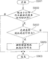
Now, explain the operation of the hard disk automatic spool initiating task of the 3rd embodiment with reference to the process flow diagram of Fig. 9.
At step S901, hard disk automatic spool initiating task begins.This task advances to step S902 and has been stored among the NVRAM 11 to check the service access identifier that whether is caused by printer work data shown in Figure 10.If detect the service access identifier (1 to 4) (at step S902) that causes by the printer work data, this task transfers to step S602 to finish corresponding processing; If do not detect, this task transfers to step S903 to finish sequence of operations.
The processing of step S602 and S603 is as shown in Figure 6.The situation of print job file on the inspection/SPOOL catalogue 302.If only there is a print job file, all print job file on the deletion/SPOOL catalogue 302.If there is no print job file, this task termination is handled.
As mentioned above, the 3rd embodiment during according to guiding in as the NVRAM 11 of nonvolatile memory the type of the service access of storage, determine whether to delete the spooking data of hard disk.
[the 4th embodiment]
Print job document control method as four embodiment of the invention is described now.
Laser beam printer as the example of image printing device of the present invention is described below, it carries out print job document control method as the 4th embodiment, the configuration of the image printing device control module of laser beam printer has also been described, and the hard disk (HD) with hierarchy catalogue.
The configuration of the laser beam printer 4000 of the 4th embodiment of conduct of execution print job document control method is as the laser beam printer 1000 of first embodiment description of reference Fig. 1.Similarly, the configuration of image printing device control module 4001 is as the image printing device control module 1001 of first embodiment description of reference Fig. 2.In the following description, the explanation and the description that repeat have been omitted.
Except being configured to of laser beam printer 1000, the laser beam printer 4000 of the 4th embodiment that employing is disposed above comprise detection laser beam printer 4000 boot process time and the time of detecting is stored in step among the NVRAM 11, and detect the previous boot process time be stored in current boot process among the NVRAM 1 between the time difference and inspection whether this difference less than the step of the schedule time.
Explain the file system of the hard disk (HD) that has the hierarchy catalogue among the 4th embodiment and the operation of normal printing job file processing task now.
Adopt the file system of HD of the hierarchy catalogue of the 4th embodiment to have the hierarchy catalogue that first embodiment as reference Fig. 3 describes.Similarly, the operation of the normal printing job file processing task of the 4th embodiment is as normal printing job file processing task shown in Figure 4.In the following description, omit the description that repeats.
The operation that the hard disk automatic spool initiating task of boot process and boot process subroutine is handled among the 4th embodiment of description now.
Except the subroutine of the hard disk startup task of step S509 was handled, the boot process of the 4th embodiment was as the process flow diagram of Fig. 5 of the boot process that first embodiment is shown.In the following description, omitted being repeated in this description of boot process.With reference to process flow diagram shown in Figure 11, only explain the operation of handling as the hard disk automatic spool initiating task of the 4th embodiment.
At step S1001, hard disk automatic spool initiating task begins.This task advances to step S1002 to obtain the current time from timer 12.At step S1003, this task computation current time and be stored among the NVRAM 11 difference between " previous boot time ".
If " current time "-" previous guiding time " is less than presetting T1 in step S1002, then this task advances to step S602 to carry out processing above-mentioned in step S606 and S603, the i.e. situation of print job file on the inspection/SPOOL catalogue 302.If only there is a print job file, all print job file on the deletion/SPOOL catalogue 302 then.Then, this task transfers is to step S1003.Noticing that the T1 value is the default value in 20 seconds, also can be to be provided with arbitrarily.
If " current time "-more than or equal to T1, then this task advanced to step S1003 and was left intact " time of previous guiding " in step S1002.
At step S1003, this task obtains the current time from timer 12, and it is rewritten the previous boot time that is stored in NVRAM 11.After, this task transfers to step S104 to finish a series of processing.
As mentioned above, the 4th embodiment is according to the time interval between the pilot operationp determines whether to delete the spooking data of hard disk again.
According to the foregoing description, activate, reset or abnormal operation in carry out in the boot process, spooking all printer operations in hard disk by the deleted image printing device etc. can prevent the generation of the mistake that spooking printer operation repeats to cause in hard disk etc.
[other embodiment]
The present invention can be applied to the system that is made of several devices (for example, principal computer, interfacing equipment, reader and printer) or comprise the equipment (for example, duplicating machine or facsimile equipment) of single assembly.
When storage is used to realize that the storage medium (recording medium) of software program code of the foregoing description function is when offering system or equipment, also can reach purpose of the present invention, the program code that is stored in storage medium is read and carried out to the computing machine of this system or equipment (or CPU or MPU).In this case, the program code of reading from storage medium has been realized the function of the foregoing description, and program code stored storage medium constitutes the present invention.The function of the foregoing description not only realizes when computing machine is carried out the program code read, and according to the instruction of program code, and the operating system (OS) on the operation computing machine realizes when finishing the processing of some or all reality.
When the program code of reading from storage medium writes on the storer of the function expansion card that is inserted into computing machine or be connected to the storer of functional expansion unit of computing machine, also realize the function of the foregoing description, the CPU of function expansion card or functional expansion unit finishes part or all of actual treatment according to the instruction of program code.
When the present invention was applied to storage medium, this storage medium stores was corresponding to the program code of above-mentioned process flow diagram (Fig. 4 is to Fig. 9 and shown in Figure 11).
As mentioned above, the present invention can provide picture printing apparatus controlling method and image printing device, can prevent activate, reset or abnormal operation in when carrying out boot process, the generation of the mistake that causes by spooking printer task in the storer.
Can design many visibly different embodiment, and can not deviate from the spirit and scope of the present invention, should be appreciated that except the regulation of claims, the invention is not restricted to certain embodiments.
Claims (12)
1. control method that is used for image printing device, this image printing device have hard disk drive and the data that are used for receiving as the automatic spool device of the interim automatic spool of print job file at hard disk drive, it is characterized in that this control method comprises:
Detect step, wherein said image printing device in a series of processing of boot process, detect any one print job file whether by automatic spool in hard disk drive;
Print job file delete step, wherein when detected in described detection step job file by automatic spool when the hard disk drive, described image printing device is deleted this print job file.
2. the method for claim 1, it is characterized in that this guiding be included in activation, reset or abnormal operation in the boot process finished.
3. the method for claim 1 is characterized in that:
This method also comprises:
Operation steps is used for carrying out the abnormity processing that produces at image printing device; And
Second detects step, is used to detect the execution to abnormity processing; And
In print job file delete step,, delete this print job file when when second detects step and detect execution to abnormity processing.
4. the method for claim 1 is characterized in that:
This method also comprises:
Nonvolatile memory, and
The abnormity notifying step is used for occurring when unusual at image printing device, with unusual classifying content for cause by the print job file be unusually and not by the print job file cause unusual, and with content stores in nonvolatile memory, and
In print job file delete step, when be unusually by the print job file cause unusual the time, deletion print job file.
5. method as claimed in claim 4, it is characterized in that by the print job file storer overflows comprising unusually of causing, exceptional instructions, download is overflowed and invalid form at least a.
6. the method for claim 1 is characterized in that this method also comprises:
Be used to store the nonvolatile memory of boot time,
The boot time step of updating, the time that is used for detecting boot time and will being stored in nonvolatile memory is updated to the detected time,
Comparison step is used for relatively being stored in the time of nonvolatile memory and the difference between the boot time, and
In print job file delete step, in the time of in difference drops on preset time, delete this print job file.
7. image printing device, have hard disk drive and the data that are used for receiving as the automatic spool device of the interim automatic spool of print job file at hard disk drive, it is characterized in that comprising:
Pick-up unit, be used for a series of processing in boot process detect any one print job file whether by automatic spool in hard disk drive; And
Print job file delete device is used for being deleted this by the print job file of automatic spool to hard disk drive by automatic spool during to hard disk drive detecting the print job file.
8. equipment as claimed in claim 7, it is characterized in that this guiding be included in activation, reset or abnormal operation in the boot process finished.
9. equipment as claimed in claim 7 is characterized in that:
This equipment also comprises:
Operating means is used for carrying out the abnormity processing that produces at image printing device, and
Second pick-up unit is used to detect the execution to abnormity processing, and
When described second pick-up unit detected execution for abnormity processing, described print job file delete device was deleted this print job file.
10. equipment as claimed in claim 7 is characterized in that:
This equipment also comprises:
Nonvolatile memory, and
The abnormity notifying device is used for occurring when unusual at image printing device, with unusual classifying content for cause by the print job file be unusually and not by the print job file cause unusual, and with content stores in described nonvolatile memory, and
When be unusually by the print job file cause unusual the time, described print job file delete device deletion print job file.
11. equipment as claimed in claim 10, it is characterized in that by the print job file storer overflows comprising unusually of causing, exceptional instructions, download is overflowed and invalid form at least a.
12. equipment as claimed in claim 7 is characterized in that this equipment also comprises:
Nonvolatile memory is used to store boot time,
The boot time updating device is used to detect boot time, and the time that will be stored in described nonvolatile memory be updated to the detected time, and
Comparison means is used for relatively being stored in the time of described nonvolatile memory and the difference between the boot time, and
In the time of in difference drops on preset time, described print job file delete device deletion print job file.
Applications Claiming Priority (2)
| Application Number | Priority Date | Filing Date | Title |
|---|---|---|---|
| JP055649/2001 | 2001-02-28 | ||
| JP2001055649A JP4454875B2 (en) | 2001-02-28 | 2001-02-28 | Image recording apparatus control method and image recording apparatus |
Publications (2)
| Publication Number | Publication Date |
|---|---|
| CN1373417A CN1373417A (en) | 2002-10-09 |
| CN1260649C true CN1260649C (en) | 2006-06-21 |
Family
ID=18915804
Family Applications (1)
| Application Number | Title | Priority Date | Filing Date |
|---|---|---|---|
| CN02106436.9A Expired - Fee Related CN1260649C (en) | 2001-02-28 | 2002-02-28 | Picture printing apparatus controlling method and picture printing apparatus |
Country Status (3)
| Country | Link |
|---|---|
| US (2) | US7050183B2 (en) |
| JP (1) | JP4454875B2 (en) |
| CN (1) | CN1260649C (en) |
Families Citing this family (12)
| Publication number | Priority date | Publication date | Assignee | Title |
|---|---|---|---|---|
| EP1437652A3 (en) * | 2002-11-26 | 2004-11-03 | Ricoh Company, Ltd. | Image forming apparatus that checks hardware resources before activating hardware-related programs |
| US20040246513A1 (en) * | 2003-06-03 | 2004-12-09 | Hewlett-Packard Company | Method and apparatus for crash recovery on an image forming apparatus |
| JP2005144844A (en) * | 2003-11-14 | 2005-06-09 | Canon Inc | Image forming apparatus, method of processing job, recording medium storing computer readable program, and program |
| KR100571782B1 (en) * | 2004-01-16 | 2006-04-18 | 삼성전자주식회사 | An apparatus having Self error Diagnostics for printing system and a method thereof |
| JP4428108B2 (en) * | 2004-03-24 | 2010-03-10 | 富士ゼロックス株式会社 | Processing apparatus, print processing method, print processing program, and printing system |
| JP4435699B2 (en) * | 2005-01-26 | 2010-03-24 | 京セラミタ株式会社 | Image forming apparatus |
| US7151643B2 (en) * | 2005-04-22 | 2006-12-19 | Kabushiki Kaisha Toshiba | Apparatus and method for protecting a disk drive in a hardcopy device |
| JP5072739B2 (en) * | 2008-07-02 | 2012-11-14 | キヤノン株式会社 | Image forming system, image forming apparatus, and image processing apparatus |
| US9367333B2 (en) * | 2012-07-30 | 2016-06-14 | Hewlett-Packard Development Company, L.P. | Booting a printer |
| JP6528744B2 (en) * | 2016-08-31 | 2019-06-12 | 京セラドキュメントソリューションズ株式会社 | Image forming device |
| WO2019066773A1 (en) * | 2017-09-26 | 2019-04-04 | Hewlett-Packard Development Company, L.P. | Boot image loading |
| JP7330717B2 (en) * | 2019-02-26 | 2023-08-22 | キヤノン株式会社 | Image forming apparatus and its control method |
Family Cites Families (8)
| Publication number | Priority date | Publication date | Assignee | Title |
|---|---|---|---|---|
| US6452692B1 (en) * | 1996-12-02 | 2002-09-17 | Sun Microsystems, Inc. | Networked printer server |
| TW325548B (en) | 1997-05-09 | 1998-01-21 | Ruey-Lin Shiau | Relay-type multimedia data processing apparatus and method thereof |
| US6678757B1 (en) * | 1998-03-18 | 2004-01-13 | Océ-Technologies B.V. | Print data management system and method |
| JP2002200828A (en) * | 2000-10-23 | 2002-07-16 | Canon Inc | Information processor, control method and storage medium |
| US7466442B2 (en) * | 2000-12-06 | 2008-12-16 | Eastman Kodak Company | Printing system and method for customization of a print job |
| US20020097428A1 (en) * | 2001-01-11 | 2002-07-25 | Ferlitsch Andrew R. | Methods and systems for print job interleaving |
| US7180619B2 (en) * | 2001-01-11 | 2007-02-20 | Sharp Laboratories Of America, Inc. | Methods and systems for recovering a failed print job |
| US20030020944A1 (en) * | 2001-05-17 | 2003-01-30 | International Business Machines Corporation | Printer pausing and reordering |
-
2001
- 2001-02-28 JP JP2001055649A patent/JP4454875B2/en not_active Expired - Fee Related
-
2002
- 2002-02-26 US US10/082,301 patent/US7050183B2/en not_active Expired - Fee Related
- 2002-02-28 CN CN02106436.9A patent/CN1260649C/en not_active Expired - Fee Related
-
2006
- 2006-01-12 US US11/330,098 patent/US7342676B2/en not_active Expired - Fee Related
Also Published As
| Publication number | Publication date |
|---|---|
| US20020118384A1 (en) | 2002-08-29 |
| US7342676B2 (en) | 2008-03-11 |
| US20060114511A1 (en) | 2006-06-01 |
| US7050183B2 (en) | 2006-05-23 |
| CN1373417A (en) | 2002-10-09 |
| JP2002254768A (en) | 2002-09-11 |
| JP4454875B2 (en) | 2010-04-21 |
Similar Documents
| Publication | Publication Date | Title |
|---|---|---|
| CN1092818C (en) | Printing apparatus, system having the same, and method of controlling printing apparatus | |
| CN1269018C (en) | Printing controller and method, information processor and its control method and program | |
| CN1260649C (en) | Picture printing apparatus controlling method and picture printing apparatus | |
| US20090235102A1 (en) | Information processing apparatus and control method thereof | |
| CN1701964A (en) | Image processing apparatus and image processing method for the same | |
| CN1733495A (en) | Image forming apparatus, printing apparatus and image processing method | |
| CN101030053A (en) | Printer | |
| CN1469255A (en) | Image forming apparatus, information processing system, rewriting method, rewriting program and recording medium of firmware | |
| CN1707401A (en) | Information processing apparatus and its control method | |
| CN1842124A (en) | Image processing apparatus and control method for image processing apparatus | |
| CN1885253A (en) | Printing system, image reading device and control method thereof | |
| CN1841309A (en) | Printing system, information processing apparatus, printing apparatus, and printing method | |
| CN1838058A (en) | Printing system, image reading apparatus and control method thereof | |
| US20110228304A1 (en) | Image forming apparatus and method for controlling the same | |
| CN1881955A (en) | Data processing apparatus connectable to network, and control method therefor | |
| JP2009071447A (en) | Information processor, its control method, and program | |
| CN1715070A (en) | Printing apparatus, information processing apparatus, and control method therefor | |
| JP5545271B2 (en) | Image processing system, image processing apparatus, display apparatus, image processing system control method, and image processing system control program | |
| CN1734412A (en) | Status information processor | |
| JP2009124522A (en) | Image forming apparatus | |
| CN1758698A (en) | Be used for the directly Apparatus and method for of printing | |
| US9900454B2 (en) | Image forming apparatus, job processing control method and non-transitory computer-readable storage medium storing job processing control program | |
| CN1628990A (en) | Printing system, control method therefor, and print control method, host apparatus, and printer therewith | |
| CN1447584A (en) | Image forming appts. | |
| CN1815380A (en) | Pattern forming apparatus and adjustment controlling means |
Legal Events
| Date | Code | Title | Description |
|---|---|---|---|
| C10 | Entry into substantive examination | ||
| SE01 | Entry into force of request for substantive examination | ||
| C06 | Publication | ||
| PB01 | Publication | ||
| C10 | Entry into substantive examination | ||
| SE01 | Entry into force of request for substantive examination | ||
| C14 | Grant of patent or utility model | ||
| GR01 | Patent grant | ||
| CF01 | Termination of patent right due to non-payment of annual fee |
Granted publication date: 20060621 Termination date: 20160228 |
|
| CF01 | Termination of patent right due to non-payment of annual fee |