CN1257625C - Multiple-carrier transmission device and multiple-carrier transmission method - Google Patents
Multiple-carrier transmission device and multiple-carrier transmission method Download PDFInfo
- Publication number
- CN1257625C CN1257625C CNB031314422A CN03131442A CN1257625C CN 1257625 C CN1257625 C CN 1257625C CN B031314422 A CNB031314422 A CN B031314422A CN 03131442 A CN03131442 A CN 03131442A CN 1257625 C CN1257625 C CN 1257625C
- Authority
- CN
- China
- Prior art keywords
- designated symbol
- transmitter
- spreading factor
- subcarrier
- carrier transmission
- Prior art date
- Legal status (The legal status is an assumption and is not a legal conclusion. Google has not performed a legal analysis and makes no representation as to the accuracy of the status listed.)
- Expired - Lifetime
Links
- 230000005540 biological transmission Effects 0.000 title claims abstract description 102
- 238000000034 method Methods 0.000 title claims abstract description 43
- 239000000969 carrier Substances 0.000 claims abstract description 8
- 108010003272 Hyaluronate lyase Proteins 0.000 claims description 65
- 230000008859 change Effects 0.000 claims description 31
- 238000010586 diagram Methods 0.000 description 11
- 230000008034 disappearance Effects 0.000 description 4
- 230000000694 effects Effects 0.000 description 4
- YBJHBAHKTGYVGT-ZKWXMUAHSA-N (+)-Biotin Chemical compound N1C(=O)N[C@@H]2[C@H](CCCCC(=O)O)SC[C@@H]21 YBJHBAHKTGYVGT-ZKWXMUAHSA-N 0.000 description 2
- 230000008901 benefit Effects 0.000 description 2
- 238000006243 chemical reaction Methods 0.000 description 2
- 238000004891 communication Methods 0.000 description 2
- 230000006872 improvement Effects 0.000 description 2
- 238000012544 monitoring process Methods 0.000 description 2
- 230000008569 process Effects 0.000 description 2
- 230000000644 propagated effect Effects 0.000 description 2
- FEPMHVLSLDOMQC-UHFFFAOYSA-N virginiamycin-S1 Natural products CC1OC(=O)C(C=2C=CC=CC=2)NC(=O)C2CC(=O)CCN2C(=O)C(CC=2C=CC=CC=2)N(C)C(=O)C2CCCN2C(=O)C(CC)NC(=O)C1NC(=O)C1=NC=CC=C1O FEPMHVLSLDOMQC-UHFFFAOYSA-N 0.000 description 2
- 238000013459 approach Methods 0.000 description 1
- 238000007796 conventional method Methods 0.000 description 1
- 230000008878 coupling Effects 0.000 description 1
- 238000010168 coupling process Methods 0.000 description 1
- 238000005859 coupling reaction Methods 0.000 description 1
- 230000005611 electricity Effects 0.000 description 1
- 238000005516 engineering process Methods 0.000 description 1
- 238000011835 investigation Methods 0.000 description 1
- 239000000203 mixture Substances 0.000 description 1
- 238000012797 qualification Methods 0.000 description 1
- 230000008054 signal transmission Effects 0.000 description 1
- 230000007480 spreading Effects 0.000 description 1
- 230000002123 temporal effect Effects 0.000 description 1
- 238000012546 transfer Methods 0.000 description 1
Images


Classifications
-
- H—ELECTRICITY
- H04—ELECTRIC COMMUNICATION TECHNIQUE
- H04J—MULTIPLEX COMMUNICATION
- H04J13/00—Code division multiplex systems
- H04J13/16—Code allocation
- H04J13/18—Allocation of orthogonal codes
-
- H—ELECTRICITY
- H04—ELECTRIC COMMUNICATION TECHNIQUE
- H04L—TRANSMISSION OF DIGITAL INFORMATION, e.g. TELEGRAPHIC COMMUNICATION
- H04L5/00—Arrangements affording multiple use of the transmission path
- H04L5/0001—Arrangements for dividing the transmission path
- H04L5/0014—Three-dimensional division
- H04L5/0016—Time-frequency-code
-
- H—ELECTRICITY
- H04—ELECTRIC COMMUNICATION TECHNIQUE
- H04L—TRANSMISSION OF DIGITAL INFORMATION, e.g. TELEGRAPHIC COMMUNICATION
- H04L5/00—Arrangements affording multiple use of the transmission path
- H04L5/003—Arrangements for allocating sub-channels of the transmission path
- H04L5/0048—Allocation of pilot signals, i.e. of signals known to the receiver
-
- H—ELECTRICITY
- H04—ELECTRIC COMMUNICATION TECHNIQUE
- H04L—TRANSMISSION OF DIGITAL INFORMATION, e.g. TELEGRAPHIC COMMUNICATION
- H04L5/00—Arrangements affording multiple use of the transmission path
- H04L5/003—Arrangements for allocating sub-channels of the transmission path
- H04L5/0058—Allocation criteria
- H04L5/006—Quality of the received signal, e.g. BER, SNR, water filling
Landscapes
- Engineering & Computer Science (AREA)
- Signal Processing (AREA)
- Computer Networks & Wireless Communication (AREA)
- Mobile Radio Communication Systems (AREA)
- Transmitters (AREA)
- Digital Transmission Methods That Use Modulated Carrier Waves (AREA)
Abstract
The object of the present invention is to provide a transmitter for multi-carrier transmission and multi-carriertransmitting method for allocating pilot channels to radio frames, in consideration of interference with other pilot channels. The present invention relates to the transmitter for multi-carrier transmission configured to transmit a plurality of sub-carriers having at least one pilot symbol duration. The transmitter according to the present invention comprises a pilot symbol allocater configured to allocate a plurality of pilot symbol patterns which are orthogonal to each other, to the at least one pilot symbol durations in at least two sub-carriers.
Description
Technical field
The present invention relates to be used for transmitter and the multicarrier transfer approach that multicarrier transmits.
Background technology
In recent years, the radio transmission system that uses multicarrier to transmit furthers investigate.
For example " IEEE802.11a ", it limits the radio transmission system that uses OFDM (orthogonal frequency divides the location multiplexing) as the LAN of radio standard.
The radio access system for example MC/DS-CDMA (multicarrier/direct sequence-code division multiple access) and MC-CDMA (multi-carrier-wave-CDMA) plan as with the radio transmission system of multi-carrier transmission with CDMA (code division multiple access).
As shown in Figure 1, the extended code multiplex system 13
1Use the extended code spread data symbol to 13n, the time base in, by transmitting a plurality of DS-CDMA signals in parallel on configuration (conversion) spread data symbol (circuit wafer) and the subcarrier in MC/DS-CDMA.
As shown in Figure 2, the extended code multiplex system 13
1Use the extended code spread data symbol to 13n, configuration (conversion) spread data symbol (chip) in a plurality of subcarriers, and the data symbol of transmission configuration (MC-CDMA signal) in parallel on the subcarrier in MC-CDMA.
In this way, the reason of using the radio transmission system of the multi-carrier transmission made further investigation is that multi-carrier transmission is propagated for multichannel a tolerance is arranged, and it sends to a receiver by signal from a transmitter by a plurality of transmission paths and produces.
When the multichannel propagation occurs, a problem is arranged, promptly arrive the signal recently of receiver and relate to the signal coherence that early receives.
Yet in multi-carrier transmission, the length of signal becomes longer, and the length of the symbol that the retardation ratio between the signal (for example, at the symbol on the #L of path) of early signal (for example, at the symbol on the #1 of path) and delay is shown in Figure 3 is little.Therefore, in multi-carrier transmission, reduced the influence of the interference that produces by multipath propagation.
Institute's information transmitted is applied on the amplitude of the signal of being propagated by transmitter or phase place.Therefore, receiver need be eliminated and appear at the interior amplitude of propagation path and/or any change of phase place, and reformulates the information that is applied on amplitude or phase place.
Between transmitter and receiver, be used for the method for transmission symbol image (designated symbol image) and estimate amplitude on the present propagation path and/or the variation of phase place is well-known, here, amplitude and the phase place in transmitter and the receiver all is well-known.
Therefore, in multi-carrier transmission, the indication passage that makes up multiplexed designated symbol image is very important.
About structure multi-carrier transmission indication passage, structure indication passage has been disclosed in the JP20001-203665 document in OFDM, the configuration of the designated symbol in MC/DS-CDMA has been disclosed among the Japan Patent JP2001-244913, and structure indication passage has been disclosed in the JP2001-197037 document in MC/CDMA.In above-mentioned document, the time base, frequency (subcarrier) or code at least one aspect disclosed the relevant multiplexing designated symbol image of structure.
In the time base of two dimension and the method for subcarrier direction spread data symbol, that is to say, a plurality of marking wave in a plurality of subcarriers on the phase method of spread data symbol then be disclosed in " using among the OFDM-CDMA of a kind of method of expansion time and frequency range synchronously (the technical report RCS-200-3 that publishes by electricity, information and Communication Engineering association) ".
Yet the problem that the structure of traditional indication passage exists is that the interference effect between the multiplexed indication passage on the radio frame is not paid attention to.
The time base or subcarrier at least one aspect the conventional method of spread data symbol to have a problem be that the quality of the signal transmission characteristics of each method depends on the situation of route of transmission to a great extent.
Summary of the invention
The application based on and require in the priority of the p2002-142114 of Japanese patent application No. formerly of on May 16th, 2002 application; The full content of this application is cited and comprises in this application.
In view of afore-mentioned, the object of the present invention is to provide a kind of transmitter that is applicable to multi-carrier transmission and consider the multicarrier transmitting method that distributes the indication passage with the interference of other indication passage to radio frame.
Another object of the present invention provides the transmitter that is used for multi-carrier transmission and considers the transmitter that is used for multi-carrier transmission and the situation of the propagation path between the receiver and be used to control the multicarrier transmitting method of extended method.
First aspect of the present invention is one and is used for transmitting the transmitter of the multi-carrier transmission of a plurality of subcarriers having at least one designated symbol ripple phase, and it comprises that one is assigned to the designator distributor of the gamut of at least one the designated symbol ripple phase at least two subcarriers to each of the designated symbol image of a plurality of mutually orthogonals.
In the transmitter of multi-carrier transmission, the designator distributor preferentially changes the length of indicator chart picture according to the quantity of set designated symbol image.
In the transmitter of multi-carrier transmission, the designated symbol image preferentially disposes orthogonal variable spreading factor (OVSP) sign indicating number.
In the transmitter of multi-carrier transmission, at least one designated symbol ripple phase of at least two subcarriers, the designated symbol distributor preferably distributes the designated symbol image to any to certain portions.Be set to the designated symbol image mutually orthogonal of same section.
In the transmitter of multi-carrier transmission, the designated symbol distributor preferentially is assigned at least one designated symbol ripple phase in the adjacent sub-carriers of predetermined number to the designated symbol image.
Second aspect of the present invention is the transmitter that comprises the multi-carrier transmission of an expander and controller, and it is used to transmit the multi-carrier transmission of a plurality of subcarriers with a plurality of marking wave phases.Based on the transmitter of multi-carrier transmission and the situation between the receiver, controller is used to change subcarrier spreading factor or time base spreading factor.The whole marking wave phase in a plurality of subcarriers, the time basic spreading factor of the subcarrier spreading factor of the subcarrier direction appointment that expander use controller changes and the appointment of Shi Ji direction is expanded and transmission symbol.
In the transmitter of multi-carrier transmission, when radio channel was arranged between transmitter and the receiver, expander preferentially changed subcarrier spreading factor or time base spreading factor.
In the transmitter of multi-carrier transmission, the variation that controller is preferentially followed the route of transmission change the subcarrier spreading factor or the time base spreading factor.
The 3rd aspect of the present invention is summarised as the multicarrier transmitting method that is suitable for multi-carrier transmission, this method is used to propagate the multi-carrier transmission of a plurality of subcarriers with at least one designated symbol ripple phase, and it comprises the designated symbol ripple phase that each of the designated symbol image of a plurality of mutually orthogonals is assigned to the gamut at least two subcarriers.
In multicarrier transmitting method, preferentially change the length of designated symbol image based on the quantity of the designated symbol image that is set up.
In multicarrier transmitting method, the designated symbol image preferably has orthogonal variable spreading factor (OVSF) sign indicating number.
In multicarrier transmitting method, the designated symbol ripple phase at least two subcarriers, preferentially the designated symbol image setting is arrived any certain portions of giving in the designated symbol ripple phase of at least two subcarriers.Be set to the designated symbol image mutually orthogonal of same section.
In multicarrier transmitting method, the designated symbol image preferentially is assigned to the interior designated symbol ripple phase of adjacent sub-carriers of predetermined number.
The 4th aspect of the present invention is summarised as a multicarrier transmitting method, this method is suitable for transmitting a plurality of subcarriers with a plurality of marking wave phases, it comprises: the whole marking wave in a plurality of subcarriers is in the phase, use along the subcarrier spreading factor of subcarrier direction appointment and along the time base direction appointment time base spreading factor expansion and transmission symbol; Based on the situation of the transmitter and the propagation path between the receiver of multi-carrier transmission, change the subcarrier spreading factor or the time base spreading factor.
In multicarrier transmitting method, when radio channel is set between transmitter and the receiver, preferentially change subcarrier spreading factor or time base spreading factor.
In multicarrier transmitting method, preferentially follow the tracks of the change of conditions of propagation paths and change subcarrier spreading factor or time base spreading factor.
Description of drawings
Fig. 1 is the schematic configuration diagram that is applicable to according to the transmitter of the MC/DS-CDMA of prior art transmission.
Fig. 2 is the schematic configuration diagram of transmitter that is applicable to the MC-CDMA transmission of prior art.
Fig. 3 explains according to passing the schematic diagram of reason of minimizing that institute is produced the influence of interference by multichannel in the multi-carrier transmission of prior art.
Fig. 4 is the schematic diagram that illustrates a kind of method, and wherein the designated symbol allocation units according to the transmitter of the multi-carrier transmission of the first embodiment of the present invention distribute quadrature indication passage.
Fig. 5 is the schematic diagram that illustrates the quadrature indication passage that the designated symbol allocation units by the transmitter of the multi-carrier transmission of first embodiment of the invention distribute.
Fig. 6 is the schematic diagram that illustrates the quadrature indication passage that the designated symbol allocation units by the transmitter of the multi-carrier transmission of second embodiment of the invention distribute.
Fig. 7 is the schematic diagram that illustrates the ovsf code that belongs to quadrature indication passage that the designated symbol allocation units by the transmitter that is used for multi-carrier transmission of second embodiment of the invention distribute.
Fig. 8 is the schematic diagram that illustrates a kind of method, and wherein the designated symbol allocation units according to the transmitter of the multi-carrier transmission of the third embodiment of the present invention distribute quadrature indication passage.
Fig. 9 is the schematic diagram that illustrates a kind of method, and wherein the designated symbol distributor according to the transmitter that is used for multi-carrier transmission of the 4th embodiment of the present invention distributes quadrature indication passage.
Figure 10 illustrates according to the channel allocation that quadrature is indicated of the fourth embodiment of the present invention to arrive the schematic diagram of a kind of method of the radio frame of being made up of two channels (slot).
Figure 11 is the structural representation according to the transmitter of the multi-carrier transmission of the fifth embodiment of the present invention.
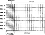
Figure 12 is a schematic diagram of explaining a kind of method, wherein according to the transmitter spread data symbol of the multi-carrier transmission of fifth embodiment of the invention.
Figure 13 is the operational flowchart of the transmitter that is used for multi-carrier transmission of explanation fifth embodiment of the invention.
Figure 14 is the flow chart of transmitter of the multi-carrier transmission of explanation fifth embodiment of the invention.
Embodiment
(first embodiment of the invention)
First embodiment of the invention will be described with reference to figure 4 to Fig. 5.
Designated symbol in the inventive method is provided with unit 17 and is provided with the designated symbol image, and is identical to the transmitter of multi-carrier transmission of the prior art shown in Figure 2 with Fig. 1 according to the structure of the transmitter of the multi-carrier transmission of first embodiment.
As shown in Figure 4, the transmitter according to the multi-carrier transmission of first embodiment transmits the radio frame that comprises at least one designated symbol ripple phase in a plurality of subcarrier # 1 to #8.
In specification, " designated symbol " is meant 1 bit (bit) information with "+1 " or " 1 ", and " designated symbol image " is meant the information of being made up of a plurality of designated symbols.As shown in Figure 5, for example the designated symbol image comprises designated symbol image # 1 "+1 ,+1+1 ,+1 ,+1 ,+1 ,+1 ,+1 " or the like.The designated symbol image can have the random length of marking wave phase.For example, designated symbol ripple phase # 1 has 8 marking wave phases.
In specification, speech " quadrature " is meant that between two designated symbol images the value being calculated by in correspondence with each other multiplication designated symbol and the result of read group total are " 0 ".In Fig. 5, for example designated symbol image # 1 "+1 ,+1+1 ,+1 ,+1 ,+1 ,+1 ,+1 " is " quadrature " for designated symbol # 2 "+1 ,-1 ,+1 ,-1 ,+1 ,-1 ,+1 ,-1 ".In specification, " quadrature designated symbol image " is meant the designated symbol image of mutually orthogonal.
In Fig. 4, can be had the length of 4 marking wave phases by the multiplexed designated symbol ripple phase at time base direction designated symbol.
In Fig. 4, designated symbol allocation units 17 can be assigned to the designated symbol ripple phase to designated symbol, and data symbol is assigned to the data symbol ripple phase.
In each radio frame, the designated symbol ripple phase only has 4 marking wave phase length, so that on whole radio frame as quadrature designated symbol image, designated symbol according to prior art is provided with the designated symbol image that unit 17 only can multiplexedly have 4 marking wave phase length, simultaneously, designated symbol image more than 4 types can not be set.
On the other hand, designated symbol allocation units 17 according to first embodiment can be assigned to a plurality of quadrature designated symbol images at a plurality of subcarriers (for example, 2 subcarriers) Nei the designated symbol ripple phase, when existence has the designated symbol ripple of 4 marking wave phases during the phase, so that the designated symbol allocation units 17 according to first embodiment can distribute the quadrature designated symbol image with 8 marking wave phase length, and maximum can be distributed 8 types quadrature designated symbol image.
Particularly adopt a plurality of antennas directional beam to be transmitted under the situation of each mobile radio station that is applied to network system in the base station, special-purpose indication passage (designated symbol image) needs for each mobile radio station.Therefore, according to first embodiment, its advantage is the quantity that can increase multiplexed quadrature designated symbol image, and also can increase the quantity of the radio channel between base station and the mobile radio station.
Fig. 4 illustrates the quadrature designated symbol image with 8 marking wave phases of the designated symbol ripple phase in duplicate allocation to two subcarrier.
According to first embodiment, the quadrature designated symbol ripple phase is assigned to the designated symbol ripple phase in a plurality of subcarrier # 1 to #8, and the length of quadrature designated symbol ripple phase becomes longer, so that increase the quantity of quadrature designated symbol image that can be multiplexed.
Distributing on a plurality of subcarrier # 1 to #8 under the situation of quadrature designated symbol image, correlation between conditions of propagation paths in subcarrier # 1 to #8 changes must be greatly, so that reduce the disappearance of the orthogonality between the indication passage that the receiver from multi-carrier transmission receives.In the multicarrier transmission systems that uses a plurality of subcarriers, the correlation between the conditions of propagation paths in adjacent sub-carriers changes is very big, so that reduce to indicate the influence of the disappearance of orthogonality between the passage.
Therefore,, quadrature designated symbol image can be multiplexed to radio frame, so that reduce influence by the interference that produces by the designated symbol image in the radio frame according to first embodiment.
Yet, according to first embodiment, designated symbol allocation units 17 are assigned to designated symbol ripple phase in a plurality of subcarriers with a plurality of designated symbol images, thereby make longer that the length of designated symbol image can be multiplexed, and when the number of the designated symbol ripple phase in each subcarrier is restricted, increase can be by the number of multiplexed designated symbol image, and increases the number that can be set at the radio channel between transmitter and the receiver.
Fig. 5 illustrates the example of quadrature designated symbol image, and it has the example by the quadrature designated symbol image of 8 marking wave phases (4 the marking wave phase * 2 subcarriers) length of designated symbol allocation units 17 distribution of first embodiment.
Fig. 5 illustrates 8 types of quadrature designated symbol image # 1 to #8.According to the designated symbol allocation units 17 of first embodiment can be in 8 designated symbol ripple phases of subcarrier #i to #i+1 multiplexed 8 types of quadrature designated symbol images.
(second embodiment of the invention)
Second embodiment of the invention will be described with reference to figure 6 and Fig. 7.Identical according to the transmitter of the structure of the transmitter of the multi-carrier transmission of second embodiment and the multi-carrier transmission of first embodiment.
In a second embodiment, arranged the designated symbol ripple phase of containing 4 marking wave phase length in each subcarrier # 1 to #8, the quadrature designated symbol image that is assigned with is identical with the quadrature designated symbol image of first embodiment.
Based on the number of the designated symbol image that is assigned with, can change the length of designated symbol image according to the designated symbol allocation units 17 of second embodiment.
In a word, as shown in Figure 6, the quadrature indicating image that designated symbol allocation units 17 can will have 4 or 8 marking wave phase length according to predetermined instruction is assigned to 1 or 2 subcarrier #i to #i+1.
As shown in Figure 6, when multiplexed indication passage (designated symbol image) when number is equal to or less than 4, designated symbol allocation units 17 can make the designated symbol image orthogonalization in 4 marking wave phases in 1 subcarrier #i or #i+1 zone.
On the other hand, when the number of multiplexed indication passage (designated symbol image) is equal to or less than 8, by designated symbol image # 5 to #8 is appended to designated symbol image # 1 to #4, designated symbol allocation units 17 can 8 marking waves designated symbol image phase in of orthogonalization on 2 subcarrier #i and #i+1.
Fig. 7 illustrates orthogonal variable spreading factor (OVSF) sign indicating number as the general example of quadrature designated symbol image.Ovsf code is " being described; referring to IEICE communication journal vol.E81-B, no.4; pp.777-784, in April, 1998 " in the literary composition of the quadrature forward direction coupling of many spreading factors of quadrature sign indicating number of the relevant relevant dynamic rate of DS-CDMA of the use of Koichi Okawa and Fumiyuki Adachi.
Based on as shown in Figure 7 ovsf code system and multiplexed indication number of active lanes, by the quadrature designated symbol image of selecting to be assigned with, use some subcarriers, can some mutual multiplexed indication passages of orthogonalization according to the designated symbol allocation units 17 of second embodiment.When multiplexed indication number of active lanes is big, use a plurality of subcarriers, designated symbol allocation units 17 can the mutual multiplexed indication passage of orthogonalization.
Based on the ovsf code system, designated symbol allocation units 17 can multiplexed indication number of active lanes more than 8 multiplications.
(the 3rd embodiment)
Third embodiment of the invention 8 will be described with reference to the accompanying drawings.Configuration according to the transmitter of the multi-carrier transmission of the 3rd embodiment is identical with the configuration of the transmitter of the multi-carrier transmission of first embodiment.
As shown in Figure 8, designated symbol image # 1 to #8 shown in Figure 5 is dispensed to any certain portions of giving in designated symbol ripple phase of at least two subcarriers of subcarrier # 1 to #6 according to the designated symbol allocation units 17 of the transmitter that is used for multi-carrier transmission of the 3rd embodiment.
In Fig. 8, designated symbol allocation units 17 are assigned to designated symbol image # 1 to #8 shown in Figure 5 the designated symbol ripple phase of the adjacent sub-carriers of predetermined number (for example, two).
Be assigned to designated symbol image # 1 to the #8 mutually orthogonal of same section #A and #B.
Described part #A is made up of the designated symbol ripple phase # 1 to #4 in designated symbol ripple phase # 1 to #4 in the subcarrier # 1 and the subcarrier # 2 adjacent with subcarrier # 1.
Described part #B is made up of the designated symbol ripple phase # 1 to #4 in designated symbol ripple phase # 1 to #4 in the subcarrier # 2 and the subcarrier # 3 adjacent with subcarrier # 2.
In other words, two parts #A and #B were made up of 4 marking wave phases of time base direction and 2 marking wave phases of subcarrier direction.
As shown in Figure 8, for example, be assigned to the designated symbol image # 1 "+1 ,+1 ,+1 ,+1 ,+1 ,+1 ,+1 ,+1 " of part #A (or #B) and be assigned to designated symbol image # 2 "+2 ,-1 ,+1 ,-1 ,+1 ,-1 ,+1 ,-1 " mutually orthogonal of part #A (or #B).
According to the 3rd embodiment, can any two subcarriers of orthogonalization, so that allow the change of the propagation path in each subcarrier of prediction.
(the 4th embodiment)
With reference to figure 9 and Figure 10 the 4th embodiment will be described.Identical according to the transmitter of the structure of the transmitter of the multi-carrier transmission of the 4th embodiment and the multi-carrier transmission of first embodiment.
As shown in Figure 9, according to the designated symbol allocation units 17 of the transmitter of the multi-carrier transmission of the 4th embodiment designated symbol image # 1 to #4 shown in Figure 6 is assigned in designated symbol ripple phase of at least two subcarriers among the subcarrier # 1 to #6 any given part (for example, #D).
In Fig. 9, designated symbol allocation units 17 specifically are used for designated symbol image # 1 to #4 is assigned to part #C and #D. in the designated symbol ripple phase
Be assigned to designated symbol image # 1 to the #4 mutually orthogonal of same section #C and #D.
Part #C comprises the designated symbol ripple phase # 1 to #4 in the subcarrier #1.Be that part #C comprises 4 marking wave phases of time base direction and 1 marking wave phase of subcarrier direction.
Part #D comprises designated symbol ripple phase # 1 to #2 in the subcarrier # 1 and the designated symbol ripple phase # 1 to #2 in the subcarrier # 2 adjacent with subcarrier #1.Two marking wave phases of base direction and two marking wave phases of subcarrier direction when in other words, part #D comprises.
As shown in Figure 9, be assigned to part #C (or #D) designated symbol image # 1 "+1 ,+1 ,+1 ,+1 " and be assigned to designated symbol image # 2 "+1 ,-1 ,+1 ,-1 ,+1 ,-1 ,+1 ,-1 " mutually orthogonal of part #C (or #D).
In the 4th embodiment, designated symbol allocation units 17 can distribute designated symbol image # 1 to #4, use 4 marking wave phases in time base direction, so that can any two the designated symbol images of quadrature, simultaneously, as shown in Figure 9, any two the designated symbol images of two marking wave phase quadratures of two marking wave phases of use time base direction and subcarrier direction.
According to the 4th embodiment, as shown in figure 10, when radio frame comprises that two channels and two indication passage is in each channel during by multiplexed transmission, use 4 marking wave phases can any two the designated symbol images of quadrature in the time base direction in radio frame, simultaneously, use two marking wave phases and use two marking wave phases can any two the designated symbol images of quadrature in time base direction in the subcarrier direction.Therefore, be equal to or can be used in the example shown in Figure 10 less than 4 orthogonal symbols images.
(the 5th embodiment)
The fifth embodiment of the present invention will be described with reference to figures 11 to 14.Figure 11 illustrates the structural representation of transmitter of the multi-carrier transmission of the 5th embodiment.Use a plurality of subcarriers, the transmitter transmission of multi-carrier transmission has the radio frame of a plurality of marking wave phases.
As shown in figure 11, the multi-carrier transmission device comprises a data symbol generation unit 11, series/parallel converting unit 12, extended code multiplication units 13
1To 13
n, subcarrier frequency multiplication units 14
1To 14
n, sum unit 15, copied cells 16
1To 16
n, condition monitoring unit 18, route of transmission and control unit 19.
Transmitter according to the multi-carrier transmission of five embodiment different with first to fourth embodiment will roughly be described.
Use the appointment of subcarrier direction the subcarrier spreading factor and the time base direction appointment spreading factor, extended code multiplication units 13
1To 13
nExpand the symbol waiting for transmission (data symbol) of the marking wave phase scope in a plurality of subcarriers.
As shown in figure 12, use subcarrier spreading factor (sf
Time=2) and time base spreading factor (sf
Frequency=4), the extended code multiplication units 13
1To 13
nSpread data symbol.
When constructing radio channel by the escape character of two dimension, wherein each has a plurality of extended codes of distinct symbols image, extended code multiplication units 13 in use
1To 13
nCan multiplexed a plurality of passages.
Condition monitoring unit, route of transmission 18 monitors the situation of propagation path, in other words, and the situation of the radio channel between the transmitter of supervision multi-carrier transmission and the receiver of multi-carrier transmission.
Based on the situation of propagation path, in other words, based on the situation of the radio channel between transmitter and receiver, control unit 19 is used for changing subcarrier spreading factor SF
FrequencyAnd/or when number base spreading factor SF
Time
When radio channel was arranged between transmitter and the receiver, control unit 19 can change subcarrier spreading factor SF
FrequencyAnd/or time base spreading factor SF
Time
Along with the change of conditions of propagation paths, control unit 19 can change subcarrier spreading factor SF
FrequencyAnd/or time base spreading factor SF
Time
When by extended code multiplication units 13
1To 13
nDuring the glyph image mutually orthogonal of the extended code of using, in transmitter, keep the orthogonality of multiplexed radio channel.Yet escape character so the orthogonality of multiplexed radio channel disappears, interferes the quality of reception of generation and receiver to descend owing to the change of phase place in the propagation path and/or amplitude is affected in radio channel.
The phase place and/or the amplitude of the symbol of time base direction change according to the maximum doppler frequency on the propagation path.The phase place of the symbol of subcarrier direction and/or amplitude change according to the expansion of the delay in the propagation path.
Therefore, based on maximum doppler frequency and/or delay expansion, in the scope of radio channel mutually orthogonal, control unit 19 is set up subcarrier transmission factor S F
FrequencyAnd/or time base spreading factor SF
TimeBasically be effectively, disappear thereby reduce the quadrature that produces by the change of conditions of propagation paths between the multiplexed radio channel.
For example, according to maximum doppler frequency f
D, at the phase place of the symbol of time base direction and/or the change of amplitude, control unit 19 is determined the " SF that satisfies condition
Time<1/f
DMaximum SF
TimeBe effectively, thereby keep having SF
TimeBy the orthogonality between the multiplexed radio channel.
Yet at according to the phase place that postpones the symbol of extended by tau in the subcarrier direction and/or the change of amplitude, control unit 19 is determined the " SF that satisfies condition
FrequencyThe maximum SF of<1/ τ
FrequencyBe effectively, to keep having SF
FrequencyBy the orthogonality between the multiplexed radio channel
SF
TimeAnd SF
FrequencyLimited according to the largest extension rate that satisfies above-mentioned condition.Yet, SF
TimeAnd SF
FrequencyCan not be subjected to the qualification of the rate of spread, the method for interference that can be by reducing other unit in the grid system is achieved.
According to the 5th embodiment, the interference effect that causes by the disappearance that reduces by the radio channel orthogonality, can the high quality transmission data symbol, the disappearance of described orthogonality be since the time the change of conditions of propagation paths in the symbol in base or the subcarrier direction cause.
Figure 13 and 14 is the operational flowchart of transmitter of the multi-carrier transmission of expression the 5th embodiment.
When the radio channel between transmitter and the receiver was set up, Figure 13 illustrated control unit 19 and changes subcarrier spreading factor SF
FrequencyAnd/or temporal extension factor S F
TimeFlow process.
Figure 14 illustrates control unit 19 and changes subcarrier spreading factor SF with the change of conditions of propagation paths
FrequencyAnd/or time base spreading factor SF
TimeFlow process.
The operation of the transmitter of multi-carrier transmission at first, is described with reference to Figure 13.
As shown in figure 13, in step 1001, produce the data symbol that is transferred to multi-carrier receiver.
In step 1002, before data symbol, based on the situation of propagation path between transmitter and the receiver, base spreading factor SF when control unit 19 is determined
TimeWith subcarrier spreading factor SF
Frequency
In step 1003, base spreading factor SF during use
TimeWith subcarrier spreading factor SF
Frequency, extended code multiplication units 13
1To 13
nSpread data symbol, subcarrier frequency multiplication units 14
1To 14
nWith sum unit 15 spread data symbol is transferred to receiver.In step 1004, finish the data symbol transmission.
Under the unaltered situation of the conditions of propagation paths between transmitter and the receiver, base spreading factor SF during by each setting
TimeWith subcarrier spreading factor SF
Frequency, control unit 19 can be followed the change data symbol of propagation path.
Secondly, the operation of the transmitter of multi-carrier transmission is described with reference to Figure 14.
As shown in figure 14, in step 1101, produce the data symbol of the transmitter that is transferred to multi-carrier transmission.
In step 1102, before data symbol, based on the situation of the propagation path between transmitter and the receiver, base spreading factor SF when control unit 19 is determined
TimeWith subcarrier spreading factor SF
Frequency
In step 1103, base spreading factor SF during use
TimeWith subcarrier spreading factor SF
Frequency, extended code multiplication units 13
1To 13
nSpread data symbol, and subcarrier frequency multiplication units 14
1To 14
nTransmit spread data symbol with sum unit 15 to receiver.
In step 1104, along with the change of the conditions of propagation paths between transmitter and the receiver, control unit 19 changes time base variable spreading factor SF
TimeWith subcarrier spreading factor SF
Frequency
Then, use the time basic spreading factor SF that upgrades
TimeWith the subcarrier spreading factor SF that upgrades
Frequency, extended code multiplication units 13
1To 13
nSpread data symbol, subcarrier frequency multiplication units 14
1To 14
nAnd sum unit 15 transmission escape characters are to receiver.In step 1105, finish data symbol.
According to method shown in Figure 14, under the frequent situation about changing of conditions of propagation paths between transmitter and the receiver, for example under the situation of receiver fast moving, follow the change of conditions of propagation paths closely, can determine suitable SF
TimeAnd SF
Frequency
In the above-described embodiments, subcarrier and concrete the writing exactly of the number of marking wave phase, but the invention is not restricted to specifically use those subcarriers and the number of marking wave phase.
Consider and adopt the disturbed condition of other indication passage of similar fashion for the foregoing description, use the m designated symbol ripple phase in the n subcarrier that is determined based on the length of set designated symbol image, the present invention can be applied in the concrete structure.At this, " m " and " n " can be positive integers, identical or greater than 1.
The transmitter of multi-carrier transmission of the present invention can adopt a kind of like this mode to determine " m " and " n ", promptly " m " and " n " be square or 2 than the high order power, when using the OVSY sign indicating number, " n " and " m " multiplied result has the length of designated symbol image.
When using other yard, the multi-carrier transmission device do not need " m " and " n " to be square or 2 than the high order power.
(effect of the present invention and effect)
Consider and the interference of other indication passage that the present invention can provide a kind of transmitter and multicarrier transmitting method of multi-carrier transmission, it allows the designated symbol image setting in radio frame.
Consider the situation of the propagation path between the receiver of the transmitter of multi-carrier transmission and multi-carrier transmission, the present invention can provide the transmitter of multi-carrier transmission and the method for multi-carrier transmission, and this method can be controlled transmission method.
Other advantage of the present invention and improvement will be to realize at an easy rate for those skilled in the art.Therefore, the present invention its be not limited to aspect main special structure and in this article shown in exemplary embodiments.In fact, the various improvement that may make will can not break away from by additional claims and its common inventive principle or scope that equivalent limited.
Claims (16)
1. transmit the transmitter of the multi-carrier transmission of a plurality of subcarriers, comprising with at least one designated symbol ripple phase:
Each of a plurality of designated symbol images of mutually orthogonal is assigned to the designated symbol distributor of the gamut of at least one the designated symbol ripple phase at least two subcarriers.
2. according to the described transmitter of claim 1, it is characterized in that: the designated symbol distributor changes the length of designated symbol image based on the quantity of the designated symbol image that is assigned with.
3. according to the described transmitter of claim 1, it is characterized in that: designated symbol image configurations orthogonal variable spreading factor sign indicating number.
4. according to the described transmitter of claim 1, it is characterized in that: the designated symbol distributor is assigned to the designated symbol image any certain portions of giving of at least one the designated symbol ripple phase at least two subcarriers; Simultaneously, be assigned to the designated symbol image mutually orthogonal of same section.
5. according to the described transmitter of claim 1, it is characterized in that: the designated symbol distributor is assigned to the designated symbol image at least one the designated symbol ripple phase in the adjacent sub-carriers of predetermined number.
6. be used to transmit the transmitter of the multi-carrier transmission of a plurality of subcarriers with a plurality of marking wave phases, it comprises:
Situation based on the transmitter and the propagation path between the receiver of multi-carrier transmission, be used to change the subcarrier spreading factor or the time base spreading factor controller; With
Use that this controller changes the subcarrier spreading factor of subcarrier direction appointment and the time base direction appointment time base spreading factor, the marking wave phase range expansion in a plurality of subcarriers and the expander of transmission symbol.
7. according to the described transmitter of claim 6, it is characterized in that: when radio channel is set between transmitter and the receiver, described controller is based on the situation of the transmitter and the propagation path between the receiver of multi-carrier transmission, change the subcarrier spreading factor or the time base spreading factor.
8. according to the described transmitter of claim 6, it is characterized in that: with the change of conditions of propagation paths, controller change the subcarrier spreading factor or the time base spreading factor.
9. be used to transmit the transmission method of the multi-carrier transmission of a plurality of subcarriers with at least one designated symbol ripple phase, it comprises: each of the designated symbol image of a plurality of mutually orthogonals is assigned to the gamut of at least one the designated symbol ripple phase at least two subcarriers.
10. according to the described multicarrier transmitting method of claim 9, it is characterized in that: the length that changes the designated symbol image based on the number of the designated symbol image that is assigned with.
11., it is characterized in that: designated symbol image configurations orthogonal variable spreading factor sign indicating number according to the described multicarrier transmitting method of claim 9.
12. according to the described multicarrier transmitting method of claim 9, it is characterized in that: the designated symbol image is assigned to any certain portions of giving of at least one the designated symbol ripple phase at least two subcarriers; With
Be assigned to the designated symbol image mutually orthogonal of same section.
13. according to the described multicarrier transmitting method of claim 9.It is characterized in that: the designated symbol image is assigned at least one interior designated symbol ripple phase of adjacent sub-carriers of predetermined number.
14. be used to transmit the multicarrier transmitting method of a plurality of subcarriers with a plurality of marking wave phases, it comprises:
Use the subcarrier spreading factor of subcarrier direction appointment and the time base direction appointment time base spreading factor, marking wave phase range expansion and transmission symbol in a plurality of subcarriers;
Based on the situation of the transmitter and the propagation path between the receiver of multi-carrier transmission, change the subcarrier spreading factor or the time base spreading factor.
15. according to the described multicarrier transmitting method of claim 14, it is characterized in that: when radio channel is arranged between transmitter and the receiver, based on the situation of the transmitter and the propagation path between the receiver of multi-carrier transmission, change the subcarrier spreading factor or the time base spreading factor.
16., it is characterized in that according to the described multicarrier transmitting method of claim 14: along with the variation of conditions of propagation paths change the subcarrier spreading factor or the time base spreading factor.
Applications Claiming Priority (2)
| Application Number | Priority Date | Filing Date | Title |
|---|---|---|---|
| JP2002142114 | 2002-05-16 | ||
| JP2002142114 | 2002-05-16 |
Publications (2)
| Publication Number | Publication Date |
|---|---|
| CN1461121A CN1461121A (en) | 2003-12-10 |
| CN1257625C true CN1257625C (en) | 2006-05-24 |
Family
ID=29267821
Family Applications (1)
| Application Number | Title | Priority Date | Filing Date |
|---|---|---|---|
| CNB031314422A Expired - Lifetime CN1257625C (en) | 2002-05-16 | 2003-05-16 | Multiple-carrier transmission device and multiple-carrier transmission method |
Country Status (8)
| Country | Link |
|---|---|
| US (1) | US7864739B2 (en) |
| EP (1) | EP1363434A3 (en) |
| JP (1) | JP4963494B2 (en) |
| KR (1) | KR100522387B1 (en) |
| CN (1) | CN1257625C (en) |
| AU (1) | AU2003204216B2 (en) |
| CA (1) | CA2428576C (en) |
| SG (1) | SG110049A1 (en) |
Families Citing this family (23)
| Publication number | Priority date | Publication date | Assignee | Title |
|---|---|---|---|---|
| JP2005057429A (en) * | 2003-08-01 | 2005-03-03 | Nec Corp | Cdma communication device and its method |
| EP2560316B1 (en) | 2003-08-12 | 2019-07-24 | Godo Kaisha IP Bridge 1 | Radio communication apparatus and pilot symbol transmission method |
| EP1542488A1 (en) * | 2003-12-12 | 2005-06-15 | Telefonaktiebolaget LM Ericsson (publ) | Method and apparatus for allocating a pilot signal adapted to the channel characteristics |
| US7397839B2 (en) | 2004-01-27 | 2008-07-08 | Ntt Docomo, Inc. | OFDM communication system and method |
| WO2005081439A1 (en) | 2004-02-13 | 2005-09-01 | Neocific, Inc. | Methods and apparatus for multi-carrier communication systems with adaptive transmission and feedback |
| EP1714405A4 (en) * | 2004-02-14 | 2008-01-23 | Samsung Electronics Co Ltd | Method for reusing ovsf codes of allocated physical channels for transmitting data via enhanced up-link in cdma |
| CN1965513B (en) | 2004-05-01 | 2014-11-26 | 桥扬科技有限公司 | Methods and apparatus for communication with time-division duplexing |
| US8027243B2 (en) * | 2004-06-25 | 2011-09-27 | Lg Electronics Inc. | Allocation of radio resource in orthogonal frequency division multiplexing system |
| GB2415872B (en) * | 2004-06-30 | 2007-09-05 | Samsung Electronics Co Ltd | Multicarrier transmission systems |
| US8000221B2 (en) * | 2004-07-20 | 2011-08-16 | Qualcomm, Incorporated | Adaptive pilot insertion for a MIMO-OFDM system |
| US20080008256A1 (en) * | 2004-08-02 | 2008-01-10 | Matshushita Electric Industrial Co., Ltd. | Ofdm Transmitting Apparatus, Ofdm Receiving Apparatus, and Their Methods |
| US20060045192A1 (en) * | 2004-08-25 | 2006-03-02 | Hiroshi Hayashi | Method and apparatus for pilot channel transmission and reception within a multi-carrier communication system |
| JP4598004B2 (en) * | 2004-12-22 | 2010-12-15 | パナソニック株式会社 | Wireless communication method, communication terminal apparatus, and wireless communication system |
| US7936740B2 (en) * | 2005-02-17 | 2011-05-03 | Samsung Electronics Co., Ltd. | Radio transmission apparatus and method, radio reception apparatus and method, transmitting and receiving method, and recording medium |
| JP4526977B2 (en) * | 2005-03-02 | 2010-08-18 | 株式会社エヌ・ティ・ティ・ドコモ | Transmitter and transmission control method |
| JPWO2006114932A1 (en) * | 2005-04-18 | 2008-12-11 | シャープ株式会社 | Wireless communication apparatus and wireless communication method |
| EP1780968A1 (en) * | 2005-10-28 | 2007-05-02 | Alcatel Lucent | OFDM based transmission in a cellular single frequency network with a pilot adapted channel multiplexing structure |
| KR100927919B1 (en) | 2006-11-01 | 2009-11-19 | 엘지전자 주식회사 | Pilot assignment method |
| US8279743B2 (en) | 2007-05-31 | 2012-10-02 | Telefonaktiebolaget Lm Ericsson (Publ) | Method for interference estimation for orthogonal pilot patterns |
| CN101383793B (en) * | 2007-09-03 | 2013-01-30 | 华为技术有限公司 | Method, apparatus and system for signal transmission and channel estimation |
| AU2009217407C1 (en) | 2008-10-09 | 2015-07-23 | Sony Corporation | New frame and data pattern structure for multi-carrier systems |
| US8934330B2 (en) * | 2009-12-29 | 2015-01-13 | Thomson Licensing | Method and apparatus for channel estimation |
| AU2011203186A1 (en) | 2010-07-01 | 2012-01-19 | Aristocrat Technologies Australia Pty Limited | A method of gaming, a gaming system, and a game controller |
Family Cites Families (23)
| Publication number | Priority date | Publication date | Assignee | Title |
|---|---|---|---|---|
| US6359923B1 (en) | 1997-12-18 | 2002-03-19 | At&T Wireless Services, Inc. | Highly bandwidth efficient communications |
| US5982327A (en) * | 1998-01-12 | 1999-11-09 | Motorola, Inc. | Adaptive array method, device, base station and subscriber unit |
| EP0939527B1 (en) * | 1998-02-18 | 2007-12-05 | Sony Deutschland GmbH | Mapping of multicarrier signals into GSM time slots |
| US6373861B1 (en) | 1998-12-01 | 2002-04-16 | Samsung Electronics Co, Ltd. | Frequency synchronizing device for OFDM/CDMA system |
| JP2000201134A (en) | 1999-01-06 | 2000-07-18 | Ntt Mobil Communication Network Inc | Method for transmitting multi-carrier/ds-cdma and demodulation device |
| JP3236273B2 (en) * | 1999-05-17 | 2001-12-10 | 三菱電機株式会社 | Multi-carrier transmission system and multi-carrier modulation method |
| US6865169B1 (en) * | 1999-11-02 | 2005-03-08 | Ipwireless, Inc. | Cellular wireless internet access system using spread spectrum and internet protocol |
| KR20010058248A (en) | 1999-12-27 | 2001-07-05 | 오길록 | Pilot Transmission Method of Multi-carrier CDMA Reverse Link for Channel Estimation |
| JP3522619B2 (en) | 2000-01-05 | 2004-04-26 | 株式会社エヌ・ティ・ティ・ドコモ | Transmitter in multi-carrier CDMA transmission system |
| JP3581072B2 (en) | 2000-01-24 | 2004-10-27 | 株式会社エヌ・ティ・ティ・ドコモ | Channel configuration method and base station using the method |
| JP3526254B2 (en) | 2000-02-25 | 2004-05-10 | 株式会社エヌ・ティ・ティ・ドコモ | Configuration of Downlink Channel in Multicarrier / DS-CDMA Mobile Communication System |
| SG108240A1 (en) | 2000-02-23 | 2005-01-28 | Ntt Docomo Inc | Multi-carrier cdma radio transmitting method and apparatus, and channel estimation method and apparatus for multi-carrier cdma radio transmitting system |
| JP2002190788A (en) * | 2000-03-17 | 2002-07-05 | Matsushita Electric Ind Co Ltd | Radio communication equipment and method |
| ES2248330T3 (en) | 2000-05-25 | 2006-03-16 | Samsung Electronics Co., Ltd. | APPARATUS AND METHOD FOR THE DIVERSITY OF TRANSMISSION THAT USE MORE THAN TWO ANTENNAS. |
| EP1170897B1 (en) * | 2000-07-05 | 2020-01-15 | Wi-Fi One Technologies International Limited | Pilot pattern design for a STTD scheme in an OFDM system |
| CN1386344A (en) | 2000-07-26 | 2002-12-18 | 三菱电机株式会社 | Multi-carrier CDMA communication device, multi-carrier CDMA transmitting device, and multi-carrier CDMA receiving device |
| EP1178641B1 (en) | 2000-08-01 | 2007-07-25 | Sony Deutschland GmbH | Frequency reuse scheme for OFDM systems |
| JP2003046481A (en) * | 2001-07-31 | 2003-02-14 | Matsushita Electric Ind Co Ltd | Data transmitter and data transmission method |
| JP3628987B2 (en) * | 2001-07-31 | 2005-03-16 | 松下電器産業株式会社 | Wireless communication apparatus and wireless communication method |
| JP2003101511A (en) * | 2001-09-26 | 2003-04-04 | Yrp Mobile Telecommunications Key Tech Res Lab Co Ltd | Multi-carrier spread spectrum communication apparatus and communication system thereof |
| AU2002219573A1 (en) | 2002-01-10 | 2003-07-30 | Fujitsu Limited | Pilot multiplex method in ofdm system and ofdm receiving method |
| JP4334274B2 (en) * | 2002-05-16 | 2009-09-30 | 株式会社エヌ・ティ・ティ・ドコモ | Multi-carrier transmission transmitter and multi-carrier transmission method |
| US6999467B2 (en) * | 2003-07-28 | 2006-02-14 | Motorola, Inc. | Method and apparatus for transmission and reception within an OFDM communication system |
-
2003
- 2003-05-13 CA CA 2428576 patent/CA2428576C/en not_active Expired - Fee Related
- 2003-05-14 SG SG200302780A patent/SG110049A1/en unknown
- 2003-05-14 US US10/437,055 patent/US7864739B2/en active Active
- 2003-05-15 AU AU2003204216A patent/AU2003204216B2/en not_active Ceased
- 2003-05-15 EP EP20030009890 patent/EP1363434A3/en not_active Withdrawn
- 2003-05-16 KR KR10-2003-0031142A patent/KR100522387B1/en not_active IP Right Cessation
- 2003-05-16 CN CNB031314422A patent/CN1257625C/en not_active Expired - Lifetime
-
2008
- 2008-12-01 JP JP2008306866A patent/JP4963494B2/en not_active Expired - Lifetime
Also Published As
| Publication number | Publication date |
|---|---|
| CN1461121A (en) | 2003-12-10 |
| JP4963494B2 (en) | 2012-06-27 |
| US20030214927A1 (en) | 2003-11-20 |
| AU2003204216A1 (en) | 2003-12-04 |
| KR20030089498A (en) | 2003-11-21 |
| EP1363434A3 (en) | 2007-01-17 |
| AU2003204216B2 (en) | 2009-05-07 |
| CA2428576C (en) | 2008-10-07 |
| EP1363434A2 (en) | 2003-11-19 |
| JP2009095045A (en) | 2009-04-30 |
| CA2428576A1 (en) | 2003-11-16 |
| US7864739B2 (en) | 2011-01-04 |
| KR100522387B1 (en) | 2005-10-18 |
| SG110049A1 (en) | 2005-04-28 |
Similar Documents
| Publication | Publication Date | Title |
|---|---|---|
| CN1257625C (en) | Multiple-carrier transmission device and multiple-carrier transmission method | |
| CN1324926C (en) | Method for controlling operational states of a MAC layer in an OFDM mobile communication system | |
| CN101064564A (en) | Wireless communication system, pilot sequence allocation apparatus, and mobile station | |
| CN1258272C (en) | Apparatus and method for gated transmission in CDMA communication system | |
| CN1150796C (en) | Method and apparatus for soft handoff in a CDMA communication system | |
| CN1886904A (en) | Interference management for soft handoff and broadcast services in a wireless frequency hopping communication system | |
| CN1364358A (en) | Radio communication apparatus and method | |
| CN1943143A (en) | Apparatus and method for controlling transmission power in communication systems using orthogonal frequency division multiple access scheme | |
| CN1366748A (en) | Base station apparatus and radio communication method | |
| CN1941687A (en) | Method for duplicating broadcasting service channel and non-broadcasting service channel | |
| KR101288369B1 (en) | Transmitting device and communication method | |
| CN1685647A (en) | Beacon signaling in a wireless system | |
| CN1347604A (en) | Apparatus and method for gated transmission in CDMA communication system | |
| CN1913418A (en) | Method for supporting changable cover by time division duplex system | |
| CN101057472A (en) | Method and apparatus for arranging pilot tones in a mobile communication system | |
| CN101047429A (en) | Method of resource distribution | |
| CN1150697C (en) | TDD framing method for physical layer of wireless system | |
| CN1922810A (en) | OFDMA system and method | |
| CN1829371A (en) | Method for distributing data, a base transceiver station, a base station controller and a mobile network therefor | |
| CN101080877A (en) | Spreading code allocating method, dispreading method, transmitter, receiver, communication device, wireless base station device, and mobile terminal device | |
| CN101064701A (en) | Method for transmitting measurement pilot and its user terminal, system | |
| CN1631015A (en) | Method of managing communications in a network and the corresponding signal, transmitting device and destination terminal | |
| CN101064955A (en) | Device and method for allocating channel resource | |
| CN1175589C (en) | Device and method for expanding channel data in CDMA system by orthogonal transmitting subset | |
| CN101064904A (en) | Method for transmitting broadcasting multicasting service and system thereof |
Legal Events
| Date | Code | Title | Description |
|---|---|---|---|
| C06 | Publication | ||
| PB01 | Publication | ||
| C10 | Entry into substantive examination | ||
| SE01 | Entry into force of request for substantive examination | ||
| C14 | Grant of patent or utility model | ||
| GR01 | Patent grant | ||
| CX01 | Expiry of patent term |
Granted publication date: 20060524 |
|
| CX01 | Expiry of patent term |