CN1255384A - Dilator - Google Patents
Dilator Download PDFInfo
- Publication number
- CN1255384A CN1255384A CN99125884A CN99125884A CN1255384A CN 1255384 A CN1255384 A CN 1255384A CN 99125884 A CN99125884 A CN 99125884A CN 99125884 A CN99125884 A CN 99125884A CN 1255384 A CN1255384 A CN 1255384A
- Authority
- CN
- China
- Prior art keywords
- dilator
- support
- throw
- fragment
- throwing
- Prior art date
- Legal status (The legal status is an assumption and is not a legal conclusion. Google has not performed a legal analysis and makes no representation as to the accuracy of the status listed.)
- Pending
Links
Images


Classifications
-
- A—HUMAN NECESSITIES
- A61—MEDICAL OR VETERINARY SCIENCE; HYGIENE
- A61F—FILTERS IMPLANTABLE INTO BLOOD VESSELS; PROSTHESES; DEVICES PROVIDING PATENCY TO, OR PREVENTING COLLAPSING OF, TUBULAR STRUCTURES OF THE BODY, e.g. STENTS; ORTHOPAEDIC, NURSING OR CONTRACEPTIVE DEVICES; FOMENTATION; TREATMENT OR PROTECTION OF EYES OR EARS; BANDAGES, DRESSINGS OR ABSORBENT PADS; FIRST-AID KITS
- A61F2/00—Filters implantable into blood vessels; Prostheses, i.e. artificial substitutes or replacements for parts of the body; Appliances for connecting them with the body; Devices providing patency to, or preventing collapsing of, tubular structures of the body, e.g. stents
- A61F2/82—Devices providing patency to, or preventing collapsing of, tubular structures of the body, e.g. stents
-
- A—HUMAN NECESSITIES
- A61—MEDICAL OR VETERINARY SCIENCE; HYGIENE
- A61F—FILTERS IMPLANTABLE INTO BLOOD VESSELS; PROSTHESES; DEVICES PROVIDING PATENCY TO, OR PREVENTING COLLAPSING OF, TUBULAR STRUCTURES OF THE BODY, e.g. STENTS; ORTHOPAEDIC, NURSING OR CONTRACEPTIVE DEVICES; FOMENTATION; TREATMENT OR PROTECTION OF EYES OR EARS; BANDAGES, DRESSINGS OR ABSORBENT PADS; FIRST-AID KITS
- A61F2/00—Filters implantable into blood vessels; Prostheses, i.e. artificial substitutes or replacements for parts of the body; Appliances for connecting them with the body; Devices providing patency to, or preventing collapsing of, tubular structures of the body, e.g. stents
- A61F2/02—Prostheses implantable into the body
- A61F2/04—Hollow or tubular parts of organs, e.g. bladders, tracheae, bronchi or bile ducts
- A61F2/06—Blood vessels
- A61F2/07—Stent-grafts
-
- A—HUMAN NECESSITIES
- A61—MEDICAL OR VETERINARY SCIENCE; HYGIENE
- A61F—FILTERS IMPLANTABLE INTO BLOOD VESSELS; PROSTHESES; DEVICES PROVIDING PATENCY TO, OR PREVENTING COLLAPSING OF, TUBULAR STRUCTURES OF THE BODY, e.g. STENTS; ORTHOPAEDIC, NURSING OR CONTRACEPTIVE DEVICES; FOMENTATION; TREATMENT OR PROTECTION OF EYES OR EARS; BANDAGES, DRESSINGS OR ABSORBENT PADS; FIRST-AID KITS
- A61F2/00—Filters implantable into blood vessels; Prostheses, i.e. artificial substitutes or replacements for parts of the body; Appliances for connecting them with the body; Devices providing patency to, or preventing collapsing of, tubular structures of the body, e.g. stents
- A61F2/82—Devices providing patency to, or preventing collapsing of, tubular structures of the body, e.g. stents
- A61F2/86—Stents in a form characterised by the wire-like elements; Stents in the form characterised by a net-like or mesh-like structure
- A61F2/90—Stents in a form characterised by the wire-like elements; Stents in the form characterised by a net-like or mesh-like structure characterised by a net-like or mesh-like structure
- A61F2/91—Stents in a form characterised by the wire-like elements; Stents in the form characterised by a net-like or mesh-like structure characterised by a net-like or mesh-like structure made from perforated sheet material or tubes, e.g. perforated by laser cuts or etched holes
- A61F2/915—Stents in a form characterised by the wire-like elements; Stents in the form characterised by a net-like or mesh-like structure characterised by a net-like or mesh-like structure made from perforated sheet material or tubes, e.g. perforated by laser cuts or etched holes with bands having a meander structure, adjacent bands being connected to each other
-
- A—HUMAN NECESSITIES
- A61—MEDICAL OR VETERINARY SCIENCE; HYGIENE
- A61F—FILTERS IMPLANTABLE INTO BLOOD VESSELS; PROSTHESES; DEVICES PROVIDING PATENCY TO, OR PREVENTING COLLAPSING OF, TUBULAR STRUCTURES OF THE BODY, e.g. STENTS; ORTHOPAEDIC, NURSING OR CONTRACEPTIVE DEVICES; FOMENTATION; TREATMENT OR PROTECTION OF EYES OR EARS; BANDAGES, DRESSINGS OR ABSORBENT PADS; FIRST-AID KITS
- A61F2/00—Filters implantable into blood vessels; Prostheses, i.e. artificial substitutes or replacements for parts of the body; Appliances for connecting them with the body; Devices providing patency to, or preventing collapsing of, tubular structures of the body, e.g. stents
- A61F2/82—Devices providing patency to, or preventing collapsing of, tubular structures of the body, e.g. stents
- A61F2002/826—Devices providing patency to, or preventing collapsing of, tubular structures of the body, e.g. stents more than one stent being applied sequentially
-
- A—HUMAN NECESSITIES
- A61—MEDICAL OR VETERINARY SCIENCE; HYGIENE
- A61F—FILTERS IMPLANTABLE INTO BLOOD VESSELS; PROSTHESES; DEVICES PROVIDING PATENCY TO, OR PREVENTING COLLAPSING OF, TUBULAR STRUCTURES OF THE BODY, e.g. STENTS; ORTHOPAEDIC, NURSING OR CONTRACEPTIVE DEVICES; FOMENTATION; TREATMENT OR PROTECTION OF EYES OR EARS; BANDAGES, DRESSINGS OR ABSORBENT PADS; FIRST-AID KITS
- A61F2/00—Filters implantable into blood vessels; Prostheses, i.e. artificial substitutes or replacements for parts of the body; Appliances for connecting them with the body; Devices providing patency to, or preventing collapsing of, tubular structures of the body, e.g. stents
- A61F2/82—Devices providing patency to, or preventing collapsing of, tubular structures of the body, e.g. stents
- A61F2002/828—Means for connecting a plurality of stents allowing flexibility of the whole structure
-
- A—HUMAN NECESSITIES
- A61—MEDICAL OR VETERINARY SCIENCE; HYGIENE
- A61F—FILTERS IMPLANTABLE INTO BLOOD VESSELS; PROSTHESES; DEVICES PROVIDING PATENCY TO, OR PREVENTING COLLAPSING OF, TUBULAR STRUCTURES OF THE BODY, e.g. STENTS; ORTHOPAEDIC, NURSING OR CONTRACEPTIVE DEVICES; FOMENTATION; TREATMENT OR PROTECTION OF EYES OR EARS; BANDAGES, DRESSINGS OR ABSORBENT PADS; FIRST-AID KITS
- A61F2/00—Filters implantable into blood vessels; Prostheses, i.e. artificial substitutes or replacements for parts of the body; Appliances for connecting them with the body; Devices providing patency to, or preventing collapsing of, tubular structures of the body, e.g. stents
- A61F2/82—Devices providing patency to, or preventing collapsing of, tubular structures of the body, e.g. stents
- A61F2/86—Stents in a form characterised by the wire-like elements; Stents in the form characterised by a net-like or mesh-like structure
- A61F2/90—Stents in a form characterised by the wire-like elements; Stents in the form characterised by a net-like or mesh-like structure characterised by a net-like or mesh-like structure
- A61F2/91—Stents in a form characterised by the wire-like elements; Stents in the form characterised by a net-like or mesh-like structure characterised by a net-like or mesh-like structure made from perforated sheet material or tubes, e.g. perforated by laser cuts or etched holes
- A61F2/915—Stents in a form characterised by the wire-like elements; Stents in the form characterised by a net-like or mesh-like structure characterised by a net-like or mesh-like structure made from perforated sheet material or tubes, e.g. perforated by laser cuts or etched holes with bands having a meander structure, adjacent bands being connected to each other
- A61F2002/91533—Stents in a form characterised by the wire-like elements; Stents in the form characterised by a net-like or mesh-like structure characterised by a net-like or mesh-like structure made from perforated sheet material or tubes, e.g. perforated by laser cuts or etched holes with bands having a meander structure, adjacent bands being connected to each other characterised by the phase between adjacent bands
- A61F2002/91541—Adjacent bands are arranged out of phase
-
- A—HUMAN NECESSITIES
- A61—MEDICAL OR VETERINARY SCIENCE; HYGIENE
- A61F—FILTERS IMPLANTABLE INTO BLOOD VESSELS; PROSTHESES; DEVICES PROVIDING PATENCY TO, OR PREVENTING COLLAPSING OF, TUBULAR STRUCTURES OF THE BODY, e.g. STENTS; ORTHOPAEDIC, NURSING OR CONTRACEPTIVE DEVICES; FOMENTATION; TREATMENT OR PROTECTION OF EYES OR EARS; BANDAGES, DRESSINGS OR ABSORBENT PADS; FIRST-AID KITS
- A61F2/00—Filters implantable into blood vessels; Prostheses, i.e. artificial substitutes or replacements for parts of the body; Appliances for connecting them with the body; Devices providing patency to, or preventing collapsing of, tubular structures of the body, e.g. stents
- A61F2/82—Devices providing patency to, or preventing collapsing of, tubular structures of the body, e.g. stents
- A61F2/86—Stents in a form characterised by the wire-like elements; Stents in the form characterised by a net-like or mesh-like structure
- A61F2/90—Stents in a form characterised by the wire-like elements; Stents in the form characterised by a net-like or mesh-like structure characterised by a net-like or mesh-like structure
- A61F2/91—Stents in a form characterised by the wire-like elements; Stents in the form characterised by a net-like or mesh-like structure characterised by a net-like or mesh-like structure made from perforated sheet material or tubes, e.g. perforated by laser cuts or etched holes
- A61F2/915—Stents in a form characterised by the wire-like elements; Stents in the form characterised by a net-like or mesh-like structure characterised by a net-like or mesh-like structure made from perforated sheet material or tubes, e.g. perforated by laser cuts or etched holes with bands having a meander structure, adjacent bands being connected to each other
- A61F2002/9155—Adjacent bands being connected to each other
- A61F2002/91558—Adjacent bands being connected to each other connected peak to peak
-
- A—HUMAN NECESSITIES
- A61—MEDICAL OR VETERINARY SCIENCE; HYGIENE
- A61F—FILTERS IMPLANTABLE INTO BLOOD VESSELS; PROSTHESES; DEVICES PROVIDING PATENCY TO, OR PREVENTING COLLAPSING OF, TUBULAR STRUCTURES OF THE BODY, e.g. STENTS; ORTHOPAEDIC, NURSING OR CONTRACEPTIVE DEVICES; FOMENTATION; TREATMENT OR PROTECTION OF EYES OR EARS; BANDAGES, DRESSINGS OR ABSORBENT PADS; FIRST-AID KITS
- A61F2250/00—Special features of prostheses classified in groups A61F2/00 - A61F2/26 or A61F2/82 or A61F9/00 or A61F11/00 or subgroups thereof
- A61F2250/0058—Additional features; Implant or prostheses properties not otherwise provided for
- A61F2250/0071—Additional features; Implant or prostheses properties not otherwise provided for breakable or frangible
Abstract
A stent is provided with specific ''designated detachment'' points or zones, such that after the stent is deployed, the stress applied on the stent will cause the stent to detach at these designated detachment points or zones. When the detachment occurs completely around the circumference of the stent, the stent separates into stent segments each able to move with the vessel independently of the other stent segments. The components at the designated detachment zones may have a cross-sectional area sufficiently low so that the components will detach under the stress placed on the stent after implantation. Alternatively or additionally, the components at the designated detachment zones may be made of a material that is sufficiently weaker so that the components will detach under the stress placed on the stent after implantation. The stent may have a lower number of components at the designated detachment zones than in the stent segments.
Description
The present invention relates generally to dilator (stent), and this dilator is the interior prosthesis of implanting in vascular in vivo such as the blood vessel, is used to support vascular and makes its maintenance unimpeded, or be used for fixing and support prosthesis in the vascular other.
At the various dilators of this technical field is known.Usually prosthesis integral body is tubulose in, and can expand into diameter after the bigger expansion from less not swell diameter.In order to implant, dilator is installed in an end of conduit usually, and wherein dilator is fixed on the conduit with its less not swell diameter.By conduit, the expanse device does not pass inner chamber and reaches the place that will implant.When being in the place that will implant, dilator just expands; usually or by internal force, for example, perhaps carry out self-expanding by the permission dilator by giving the balloon inflation in the dilator; for example, allow dilator outwards to expand by removing the sleeve pipe that surrounds the self-expanding dilator.In each case, the trend that the dilator opposing vascular after the expansion narrows down, thus keep vascular not closed.
Some patent that relates to dilator comprises the U.S. Patent No. 4,733,665 of authorizing Palmaz; Authorize the U.S. Patent No. 4,800,882 and 5,282,824 of Gianturco; Authorize the U.S. Patent No. 4,856,516 and 5,116,365 of Hillstead; Authorize the U.S. Patent No. 4,886,062 and 4,969,458 of Wiktor; Authorize the U.S. Patent No. 5,019,090 of Pinchuk; Authorize the U.S. Patent No. 5,102,417 of Palmaz and Schatz; Authorize the U.S. Patent No. 5,104,404 of Wolff; Authorize the U.S. Patent No. 5,161,547 of Tower; Authorize people's such as Cardon U.S. Patent No. 5,383,892; Authorize people's such as Pinchasik U.S. Patent No. 5,449,373; Authorize people's such as Israel U.S. Patent No. 5,733,303.
A purpose of previous dilator design is to have enough radial strengths after guaranteeing to expand, so that it can sufficiently support inner chamber.Yet the dilator with high radial strength tends to also have the longitudinal rigidity higher than the vascular of its implantation.When dilator had the high longitudinal rigidity of vascular than its implantation, owing to band dilator and the stress concentration that do not match and cause with flexibility between the vascular part of dilator, the damage to vascular that takes place in the dilator end will increase.
An object of the present invention is to provide a kind of dilator, even do very longly, this dilator also can more closely mate its flexibility of implanting vascular, and the radial strength loss is less or do not have a radial strength loss.
According to one embodiment of present invention, dilator has special " specify and throw off " point, makes after arranging dilator and in the motor process of vascular, and the stress that acts on the dilator will make dilator specify drop-outs to disconnect at these.When specifying drop-outs around the circumference of dilator fully, just produce a circumference and " specified and thrown off " zone, specifying the drop-outs disengagement to make dilator be divided into two or more independent dilator fragments, each fragment can be independent of other dilator fragment and vascular moves always.Because each dilator fragment can be independent of other dilator fragment and vascular moves always, compare with long whole dilator, a series of dilator fragments have just obtained the band dilator and not with the big flexibility between dilator vascular part, thereby have reduced the stress that acts on the blood vessel wall.
Dilator is preferably designed as after disengagement, and more level and smooth by throwing off the dilator fragment end that produces, they just can not damage blood vessel wall like this.And independent dilator fragment had enough radial strengths after the shape of dilator was preferably made and throws off, and the dilator that makes disengagement cause descends less to the resistance of compressing or do not have significantly decline.
Dilator only can be designed as just throws off after implanting a period of time, and dilator will be embedded in below the neointima when throwing off like this.Like this, the remaining dilator fragment in disengagement back will be fixed on the position by neointima and can not move relative to inner chamber, that is, they can " not pack into " (telescope) mutually, thereby they can be mutually away from producing unsupported gap yet.
Can utilize many principles to realize throwing off.For example, dilator can have the enough low member of cross-sectional area in some point or zone along its length, implants back dilator under the stress that acts on the dilator like this and will preferentially throw off.Alternatively or as additional, dilator is used than the enough member of fragile material manufacture of dilator other parts can having along some point of its length or zone, like this implantation afterwards under the stress that acts on the dilator dilator will preferentially throw off.Alternatively or as additional, dilator can be designed to throw off member or the support that the zone has lesser amt specifying, and each this member will bear the load of Duoing than dilator other parts member like this.The shape of these members is made when implanting and is separated under the stress of its increase of bearing when the back dilator bears repeated stress.
The factor that helps to throw off can be used singly or in combination.For example, specify to throw off support and can have low cross-sectional area and can be made of fragile material, perhaps specify and throw off the zone and can have the member that quantity reduces, member has low cross-sectional area and/or uses and disuses and constitutes all right than weaker materials.
Figure 1 shows that the sketch map of a dilator, this dilator is whole cylindrical, has to specify between the dilator fragment and throws off the zone;
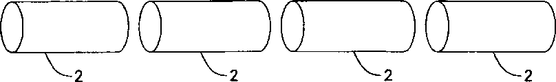
Figure 2 shows that the sketch map of Fig. 1 dilator after the disengagement, wherein dilator is divided into a series of short dilator fragments;
Figure 3 shows that the tiling figure of dilator pattern, wherein specify the element cross-section area of throwing off in the zone enough low, implant back dilator fragment under the effect that acts on the stress on the dilator like this and will throw off;
Figure 4 shows that the tiling figure that throws off Fig. 3 dilator pattern after throw off in the zone specifying;
Figure 5 shows that the tiling figure of a dilator pattern, wherein dilator has the member of lesser amt specify throwing off the zone, make each this member bear the load of increase and under the effect of the load of this increase separately.
Figure 1 shows that the whole sketch map of columniform dilator 1 that is.Dilator 1 comprises a series of by specifying the disengagement zone 3 dilator fragments 2 of separating.Specify disengagement zone 3 to comprise one or more appointments disengagement members or support (seeing Fig. 3 to 5).
Specify disengagement zone 3 to be designed to, the implantation back is specified the disengagement member or is supported and separate under the repeated stress effect that acts on the dilator 1.When the whole appointments disengagement supports that center on the dilator circumference in the specific appointment disengagement zone 3 separated, dilator itself just was divided into a series of independently dilator fragments 2, as shown in Figure 2.Specify disengagement zone 3 can be designed to implant after just throw off after a while, dilator fragment 2 will be embedded to below the neointima when throwing off like this, thereby can not move relative to inner chamber.
Those skilled in the art will be noted that the basic geometry of dilator fragment 2 can be any suitable shape, and dilator fragment 2 can be made of any suitable material.The suitable construction example of dilator fragment 2 is included in the structure shown in the U.S. Patent No. 5,733,303 of authorizing people such as Israel, and the disclosure of this patent is specially in conjunction with in this application as a reference.
Figure 3 shows that one comprises by the tiling figure that specifies the dilator pattern of throwing off the zone 3 dilator fragments 2 of separating.In the dilator of finishing, the structure of each the dilator fragment 2 among this embodiment substantially with in U.S. Patent No. 5,733, disclosed structure is corresponding in 303.Dilator fragment 2 interconnects by specifying the appointment of throwing off zone 3 to throw off member or support 4.
In this embodiment, the cross-sectional area that support 4 has minimizing is thrown off in each appointment, and it enough hangs down to allow the appointment disengagement of implantation back to support 4 and separates under the effect that acts on the stress on the dilator.With, for example, the member with reference number 5 labellings in the dilator fragment 2 is compared, throw off the reduction that supports 4 cross sections can be, for example, about tens percent.For example, throwing off support 4 can be thinner or narrow by 25% to 75% than member 5.
As additional or alternatively, these specify throw off support 4 can be by fragile material manufacture, with guarantee suitable separately.Fragile material can or be provided to be used for constituting specifying to throw off and supports 4 get the raw materials ready, and perhaps specifies to throw off and supports 4 (or specify and throw off zone 3) producing the dilator post processing, makes this processing make to specify to throw off to support 4 material and die down.
Provide to have and throw off an example that supports than the appointment of weaker materials and be, constitute whole dilator, being treated to martensite specifying to throw off to support then, and remaining member is an austenite with NiTi.For example in the dilator of being made by rustless steel (SST), another example is to make to specify the member malleableize of throwing off the zone and the segmental member of dilator is strengthened.
Except that reducing cross section, can select to specify the remaining geometry of throwing off support to realize the result who wishes.As shown in Figure 3, one arranges the width A that specifies disengagement support 4 can be narrower than the width of corresponding row's member in the dilator fragment 2, and the latter for example uses the width B of row's member of reference number 5 labellings.Width in appointment disengagement zone 3 reduces help and guarantees to throw off zone 3 disengagements in appointment under the effect of vertical repeated flex.And appointment is thrown off support 4 and can be done enough shortly in the free-ended length after reducing openly, separates the back like this and just can not stay long unsettled end.For example, specify the length of throwing off support 4 shorter than the length of member 5.
Figure 4 shows that the tiling figure that throws off Fig. 3 dilator pattern after throw off in zone 3 specifying.As shown in Figure 4, throw off the back dilator and comprise a series of separate and dilator fragments 2 independently.Still as shown in Figure 4, support 4 weak points, so separately the length of back free end 6 keeps minimum owing to specify to throw off.
Figure 5 shows that a kind of alternate design, wherein specifying disengagement zone 3, have the member 7 of lesser amt around dilator circumference dilator.In the embodiment shown in fig. 5, each is specified disengagement zone 3 to have five appointment disengagements and supports 7 around the dilator circumference.By comparison, in dilator fragment 2 interior one section this member, dilator has nine members that are labeled as member 5.Certainly, under the situation that does not depart from general concept of the present invention, can use the appointment of varying number to throw off the fragment member that supports and expand.
Specify to throw off support 7 be shaped as, in throwing off that they bear by acting on after implanting under the load effect that the stress on the dilator causes.As shown in Figure 5, specify disengagement support 7 also can have the cross-sectional area of minimizing.And, for the disengagement of the appointment among other embodiment support, specify disengagement to support 7 and also can constitute by material in addition, or can after producing dilator, handle so that material becomes more fragile specifying disengagement to support 7 or regional 3 than fragility.
Embodiment described here only is an example, and other variation can also be arranged in the scope of the present invention that is limited by accessory claim.
Claims (16)
1. be used for being implanted in the dilator of vascular, wherein this dilator comprises:
(a) a plurality of dilator fragments;
(b) be used for releasably connecting the segmental device of adjacent dilator of described a plurality of dilator fragments, the described connecting device of throwing off be fit to allow described adjacent dilator fragment response to act on describedly to throw off the physiology's stress on the connecting device and be separated from each other, wherein, be implanted in the vascular after just generation after a while is enough to allow the neointima of formation around dilator to be enough to the relative vascular of described a plurality of dilator fragments is fixed during this period of time described separating at dilator.
2. according to the dilator described in the claim 1, it is characterized in that, the described connecting device of throwing off comprises at least one appointment disengagement support, wherein specify the area of section of throwing off support enough little, make under the effect that acts on the stress on the dilator after the implantation, to specify to throw off and support and preferentially to separate.
3. according to the dilator described in the claim 1, it is characterized in that, the described connecting device of throwing off comprises at least one appointment disengagement support, wherein specify to throw off and support, under the effect that acts on the stress on the dilator after the implantation, specify like this to throw off and support and preferentially to separate by the material manufacture of comparing enough fragilities with the dilator other parts.
4. according to the dilator described in the claim 1, it is characterized in that the described connecting device of throwing off comprises at least one appointment disengagement support, wherein specifies the cross-sectional area of throwing off support less than the element cross-section area in one of described dilator fragment.
5. according to the dilator described in the claim 4, it is characterized in that, specify to throw off and support also by material manufacture than the construction material fragility in one of described dilator fragment.
6. according to the dilator described in the claim 1, it is characterized in that the described connecting device of throwing off comprises at least one appointment disengagement support, wherein specifies and throws off support by the material manufacture than the construction material fragility in one of described dilator fragment.
7. according to the dilator described in the claim 1, it is characterized in that, the described connecting device of throwing off comprises at least one appointment disengagement support in the appointment disengagement zone of dilator, wherein throw off in described appointment and specify the quantity of throwing off support to lack than the quantity of passing a planar support in the zone, this plane intersects perpendicular to the segmental axis of dilator and one of described dilator fragment.
8. according to the dilator described in the claim 7, it is characterized in that at least one specifies the cross-sectional area of throwing off support littler than the element cross-section area in one of described dilator fragment.
9. the dilator described in according to Claim 8 is characterized in that, specifies to throw off and supports also by the material manufacture than the construction material fragility in one of described dilator fragment.
10. according to the dilator described in the claim 7, it is characterized in that at least one is specified to throw off and supports by the material manufacture than the construction material fragility in one of described dilator fragment.
11. one comprises at least two dilator fragments and the dilator that at least one specifies disengagement to support;
It is characterized in that, specify the cross-sectional area of throwing off support littler than the element cross-section area in one of described dilator fragment.
12. the dilator according to described in the claim 11 is characterized in that, specifies to throw off and supports the material manufacture of also using than the construction material fragility in one of described dilator fragment.
13. according to the dilator described in the claim 11, it is characterized in that, specify to throw off and support the appointment disengagement zone that is arranged in dilator, wherein, specify the appointment of throwing off in the zone to throw off supported amount and lack than the quantity of passing a planar support, this plane intersects perpendicular to the segmental axis of dilator and one of described dilator fragment.
14. the dilator according to described in the claim 13 is characterized in that, specifies to throw off and supports the material manufacture of also using than the construction material fragility in one of described dilator fragment.
15. one comprises at least two dilator fragments and the dilator that at least one specifies disengagement to support;
It is characterized in that, specify to throw off and support by material manufacture than the construction material fragility in one of described dilator fragment.
16. according to the dilator described in the claim 15, it is characterized in that, specify to throw off and support the appointment disengagement zone that is arranged in dilator, wherein, specify the appointment of throwing off in the zone to throw off supported amount and lack than the quantity of passing a planar support, this plane intersects perpendicular to the segmental axis of dilator and one of described dilator fragment.
Applications Claiming Priority (2)
| Application Number | Priority Date | Filing Date | Title |
|---|---|---|---|
| US20483098A | 1998-12-03 | 1998-12-03 | |
| US09/204,830 | 1998-12-03 |
Publications (1)
| Publication Number | Publication Date |
|---|---|
| CN1255384A true CN1255384A (en) | 2000-06-07 |
Family
ID=22759625
Family Applications (1)
| Application Number | Title | Priority Date | Filing Date |
|---|---|---|---|
| CN99125884A Pending CN1255384A (en) | 1998-12-03 | 1999-12-02 | Dilator |
Country Status (21)
| Country | Link |
|---|---|
| US (1) | US20020107560A1 (en) |
| EP (1) | EP1005843B1 (en) |
| JP (1) | JP3682674B2 (en) |
| KR (1) | KR100325889B1 (en) |
| CN (1) | CN1255384A (en) |
| AR (1) | AR021848A1 (en) |
| AT (1) | ATE287677T1 (en) |
| AU (2) | AU757936C (en) |
| BR (1) | BR9904304A (en) |
| CA (1) | CA2281775C (en) |
| DE (2) | DE69923413T2 (en) |
| EE (1) | EE04257B1 (en) |
| GB (1) | GB2344527B (en) |
| IL (1) | IL133269A0 (en) |
| NO (1) | NO314980B1 (en) |
| NZ (1) | NZ337652A (en) |
| PL (1) | PL336834A1 (en) |
| RU (1) | RU2234288C2 (en) |
| SG (1) | SG75982A1 (en) |
| SK (1) | SK166799A3 (en) |
| WO (1) | WO2000032136A1 (en) |
Cited By (1)
| Publication number | Priority date | Publication date | Assignee | Title |
|---|---|---|---|---|
| CN105211069A (en) * | 2010-10-25 | 2016-01-06 | 朗盛德国有限责任公司 | Fungicide penta benzene pyrrole bacterium amine blends |
Families Citing this family (73)
| Publication number | Priority date | Publication date | Assignee | Title |
|---|---|---|---|---|
| US7887578B2 (en) | 1998-09-05 | 2011-02-15 | Abbott Laboratories Vascular Enterprises Limited | Stent having an expandable web structure |
| US6755856B2 (en) | 1998-09-05 | 2004-06-29 | Abbott Laboratories Vascular Enterprises Limited | Methods and apparatus for stenting comprising enhanced embolic protection, coupled with improved protection against restenosis and thrombus formation |
| US6682554B2 (en) | 1998-09-05 | 2004-01-27 | Jomed Gmbh | Methods and apparatus for a stent having an expandable web structure |
| US7815763B2 (en) * | 2001-09-28 | 2010-10-19 | Abbott Laboratories Vascular Enterprises Limited | Porous membranes for medical implants and methods of manufacture |
| US8382821B2 (en) | 1998-12-03 | 2013-02-26 | Medinol Ltd. | Helical hybrid stent |
| US6258117B1 (en) | 1999-04-15 | 2001-07-10 | Mayo Foundation For Medical Education And Research | Multi-section stent |
| US6409754B1 (en) * | 1999-07-02 | 2002-06-25 | Scimed Life Systems, Inc. | Flexible segmented stent |
| US6579308B1 (en) * | 2000-11-28 | 2003-06-17 | Scimed Life Systems, Inc. | Stent devices with detachable distal or proximal wires |
| EP1258230A3 (en) | 2001-03-29 | 2003-12-10 | CardioSafe Ltd | Balloon catheter device |
| US20030045923A1 (en) * | 2001-08-31 | 2003-03-06 | Mehran Bashiri | Hybrid balloon expandable/self expanding stent |
| US6796999B2 (en) | 2001-09-06 | 2004-09-28 | Medinol Ltd. | Self articulating stent |
| GB0121980D0 (en) | 2001-09-11 | 2001-10-31 | Cathnet Science Holding As | Expandable stent |
| US7351255B2 (en) | 2001-12-03 | 2008-04-01 | Xtent, Inc. | Stent delivery apparatus and method |
| US20040186551A1 (en) | 2003-01-17 | 2004-09-23 | Xtent, Inc. | Multiple independent nested stent structures and methods for their preparation and deployment |
| US7182779B2 (en) | 2001-12-03 | 2007-02-27 | Xtent, Inc. | Apparatus and methods for positioning prostheses for deployment from a catheter |
| US7309350B2 (en) | 2001-12-03 | 2007-12-18 | Xtent, Inc. | Apparatus and methods for deployment of vascular prostheses |
| US7147656B2 (en) | 2001-12-03 | 2006-12-12 | Xtent, Inc. | Apparatus and methods for delivery of braided prostheses |
| US7892273B2 (en) | 2001-12-03 | 2011-02-22 | Xtent, Inc. | Custom length stent apparatus |
| US7294146B2 (en) | 2001-12-03 | 2007-11-13 | Xtent, Inc. | Apparatus and methods for delivery of variable length stents |
| US8080048B2 (en) * | 2001-12-03 | 2011-12-20 | Xtent, Inc. | Stent delivery for bifurcated vessels |
| US7137993B2 (en) | 2001-12-03 | 2006-11-21 | Xtent, Inc. | Apparatus and methods for delivery of multiple distributed stents |
| US20030135266A1 (en) * | 2001-12-03 | 2003-07-17 | Xtent, Inc. | Apparatus and methods for delivery of multiple distributed stents |
| US6923829B2 (en) | 2002-11-25 | 2005-08-02 | Advanced Bio Prosthetic Surfaces, Ltd. | Implantable expandable medical devices having regions of differential mechanical properties and methods of making same |
| US7241308B2 (en) | 2003-06-09 | 2007-07-10 | Xtent, Inc. | Stent deployment systems and methods |
| US9155639B2 (en) | 2009-04-22 | 2015-10-13 | Medinol Ltd. | Helical hybrid stent |
| US9039755B2 (en) | 2003-06-27 | 2015-05-26 | Medinol Ltd. | Helical hybrid stent |
| US6840569B1 (en) * | 2003-07-22 | 2005-01-11 | Arthur Donald Leigh | Caravan |
| US8157855B2 (en) * | 2003-12-05 | 2012-04-17 | Boston Scientific Scimed, Inc. | Detachable segment stent |
| US7326236B2 (en) | 2003-12-23 | 2008-02-05 | Xtent, Inc. | Devices and methods for controlling and indicating the length of an interventional element |
| US20050182479A1 (en) * | 2004-02-13 | 2005-08-18 | Craig Bonsignore | Connector members for stents |
| US20050216043A1 (en) * | 2004-03-26 | 2005-09-29 | Blatter Duane D | Stented end graft vessel device for anastomosis and related methods for percutaneous placement |
| US7323006B2 (en) | 2004-03-30 | 2008-01-29 | Xtent, Inc. | Rapid exchange interventional devices and methods |
| US8317859B2 (en) | 2004-06-28 | 2012-11-27 | J.W. Medical Systems Ltd. | Devices and methods for controlling expandable prostheses during deployment |
| US20050288766A1 (en) | 2004-06-28 | 2005-12-29 | Xtent, Inc. | Devices and methods for controlling expandable prostheses during deployment |
| FR2881946B1 (en) | 2005-02-17 | 2008-01-04 | Jacques Seguin | DEVICE FOR THE TREATMENT OF BODILY CONDUIT AT BIFURCATION LEVEL |
| ES2764992T3 (en) | 2005-04-04 | 2020-06-05 | Flexible Stenting Solutions Inc | Flexible stent |
| EP1903999B1 (en) | 2005-04-25 | 2018-11-21 | Covidien LP | Controlled fracture connections for stents |
| US7938851B2 (en) | 2005-06-08 | 2011-05-10 | Xtent, Inc. | Devices and methods for operating and controlling interventional apparatus |
| US20060282149A1 (en) | 2005-06-08 | 2006-12-14 | Xtent, Inc., A Delaware Corporation | Apparatus and methods for deployment of multiple custom-length prostheses (II) |
| DE102005052226B4 (en) * | 2005-09-30 | 2014-09-11 | Michael Friebe | Stent for insertion into human body cavities, especially in blood vessels |
| EP1932496B1 (en) * | 2005-10-06 | 2021-12-01 | Kaneka Corporation | Stent to be placed in the living body |
| US20070100431A1 (en) * | 2005-11-03 | 2007-05-03 | Craig Bonsignore | Intraluminal medical device with strain concentrating bridge |
| EP1965730A4 (en) | 2005-12-30 | 2009-06-17 | Bard Inc C R | Stent with bio-resorbable connector and methods |
| CA2646885A1 (en) | 2006-03-20 | 2007-09-27 | Xtent, Inc. | Apparatus and methods for deployment of linked prosthetic segments |
| FR2911063B1 (en) | 2007-01-09 | 2009-03-20 | Stentys S A S Soc Par Actions | RUPTIBLE BRIDGE STRUCTURE FOR STENT, AND STENT INCLUDING SUCH BRIDGE STRUCTURES. |
| US20080199510A1 (en) | 2007-02-20 | 2008-08-21 | Xtent, Inc. | Thermo-mechanically controlled implants and methods of use |
| US8486132B2 (en) | 2007-03-22 | 2013-07-16 | J.W. Medical Systems Ltd. | Devices and methods for controlling expandable prostheses during deployment |
| US8016874B2 (en) * | 2007-05-23 | 2011-09-13 | Abbott Laboratories Vascular Enterprises Limited | Flexible stent with elevated scaffolding properties |
| US8128679B2 (en) | 2007-05-23 | 2012-03-06 | Abbott Laboratories Vascular Enterprises Limited | Flexible stent with torque-absorbing connectors |
| US7632305B2 (en) * | 2007-07-06 | 2009-12-15 | Boston Scientific Scimed, Inc. | Biodegradable connectors |
| US7988723B2 (en) | 2007-08-02 | 2011-08-02 | Flexible Stenting Solutions, Inc. | Flexible stent |
| US8906081B2 (en) | 2007-09-13 | 2014-12-09 | W. L. Gore & Associates, Inc. | Stented vascular graft |
| US8920488B2 (en) | 2007-12-20 | 2014-12-30 | Abbott Laboratories Vascular Enterprises Limited | Endoprosthesis having a stable architecture |
| US8337544B2 (en) | 2007-12-20 | 2012-12-25 | Abbott Laboratories Vascular Enterprises Limited | Endoprosthesis having flexible connectors |
| US7850726B2 (en) | 2007-12-20 | 2010-12-14 | Abbott Laboratories Vascular Enterprises Limited | Endoprosthesis having struts linked by foot extensions |
| US9101503B2 (en) | 2008-03-06 | 2015-08-11 | J.W. Medical Systems Ltd. | Apparatus having variable strut length and methods of use |
| US8882821B2 (en) | 2008-05-02 | 2014-11-11 | Cook Medical Technologies Llc | Cartridge delivery system for delivery of medical devices |
| US9005274B2 (en) | 2008-08-04 | 2015-04-14 | Stentys Sas | Method for treating a body lumen |
| US8821562B2 (en) | 2008-09-25 | 2014-09-02 | Advanced Bifurcation Systems, Inc. | Partially crimped stent |
| US11298252B2 (en) | 2008-09-25 | 2022-04-12 | Advanced Bifurcation Systems Inc. | Stent alignment during treatment of a bifurcation |
| US8769796B2 (en) | 2008-09-25 | 2014-07-08 | Advanced Bifurcation Systems, Inc. | Selective stent crimping |
| EP2344068B1 (en) | 2008-09-25 | 2022-10-19 | Advanced Bifurcation Systems Inc. | Partially crimped stent |
| US9149376B2 (en) | 2008-10-06 | 2015-10-06 | Cordis Corporation | Reconstrainable stent delivery system |
| WO2011050234A2 (en) * | 2009-10-23 | 2011-04-28 | Mayo Foundation For Medical Education And Research | Patient-specific modifiable stents |
| CA2794064A1 (en) | 2010-03-24 | 2011-09-29 | Advanced Bifurcation Systems, Inc. | Methods and systems for treating a bifurcation with provisional side branch stenting |
| CA2794080A1 (en) | 2010-03-24 | 2011-09-29 | Advanced Bifurcation Systems, Inc. | System and methods for treating a bifurcation |
| WO2011119883A1 (en) | 2010-03-24 | 2011-09-29 | Advanced Bifurcation Systems, Inc. | Stent alignment during treatment of a bifurcation |
| WO2012109382A2 (en) | 2011-02-08 | 2012-08-16 | Advanced Bifurcation Systems, Inc. | Multi-stent and multi-balloon apparatus for treating bifurcations and methods of use |
| EP3449879B1 (en) | 2011-02-08 | 2020-09-23 | Advanced Bifurcation Systems Inc. | System for treating a bifurcation with a fully crimped stent |
| CA2911226C (en) | 2013-05-23 | 2024-02-20 | S.T.S. Medical Ltd. | Shape change structure |
| WO2016084087A2 (en) | 2014-11-26 | 2016-06-02 | S.T.S. Medical Ltd. | Shape change structure for treatment of nasal conditions including sinusitis |
| DE102015102181A1 (en) | 2015-02-16 | 2016-08-18 | Biotronik Ag | Vascular support and method for producing a vascular support |
| US11628074B2 (en) * | 2021-01-19 | 2023-04-18 | Sainath Intellectual Properties, Llc | Telescoping stents |
Family Cites Families (14)
| Publication number | Priority date | Publication date | Assignee | Title |
|---|---|---|---|---|
| US4733665C2 (en) | 1985-11-07 | 2002-01-29 | Expandable Grafts Partnership | Expandable intraluminal graft and method and apparatus for implanting an expandable intraluminal graft |
| US4800882A (en) | 1987-03-13 | 1989-01-31 | Cook Incorporated | Endovascular stent and delivery system |
| US4886062A (en) | 1987-10-19 | 1989-12-12 | Medtronic, Inc. | Intravascular radially expandable stent and method of implant |
| CA1322628C (en) * | 1988-10-04 | 1993-10-05 | Richard A. Schatz | Expandable intraluminal graft |
| US4856516A (en) | 1989-01-09 | 1989-08-15 | Cordis Corporation | Endovascular stent apparatus and method |
| CA2026604A1 (en) * | 1989-10-02 | 1991-04-03 | Rodney G. Wolff | Articulated stent |
| DE9117152U1 (en) | 1990-10-09 | 1996-07-11 | Cook Inc | Stent |
| US5116365A (en) | 1991-02-22 | 1992-05-26 | Cordis Corporation | Stent apparatus and method for making |
| US5383926A (en) * | 1992-11-23 | 1995-01-24 | Children's Medical Center Corporation | Re-expandable endoprosthesis |
| US5723003A (en) * | 1994-09-13 | 1998-03-03 | Ultrasonic Sensing And Monitoring Systems | Expandable graft assembly and method of use |
| US5591197A (en) * | 1995-03-14 | 1997-01-07 | Advanced Cardiovascular Systems, Inc. | Expandable stent forming projecting barbs and method for deploying |
| EP1006938A4 (en) * | 1996-04-08 | 2000-07-05 | Iowa India Investments Company | Multiple interconnected stents and method of coating stents |
| US5807404A (en) * | 1996-09-19 | 1998-09-15 | Medinol Ltd. | Stent with variable features to optimize support and method of making such stent |
| US5836966A (en) * | 1997-05-22 | 1998-11-17 | Scimed Life Systems, Inc. | Variable expansion force stent |
-
1999
- 1999-08-31 SG SG1999004228A patent/SG75982A1/en unknown
- 1999-09-03 CA CA002281775A patent/CA2281775C/en not_active Expired - Lifetime
- 1999-09-03 AU AU47360/99A patent/AU757936C/en not_active Expired
- 1999-09-03 NZ NZ337652A patent/NZ337652A/en unknown
- 1999-09-22 BR BR9904304-1A patent/BR9904304A/en not_active IP Right Cessation
- 1999-09-30 AR ARP990104966A patent/AR021848A1/en unknown
- 1999-10-12 RU RU99121892/14A patent/RU2234288C2/en not_active IP Right Cessation
- 1999-10-18 AT AT99120028T patent/ATE287677T1/en not_active IP Right Cessation
- 1999-10-18 DE DE69923413T patent/DE69923413T2/en not_active Expired - Lifetime
- 1999-10-18 EP EP99120028A patent/EP1005843B1/en not_active Expired - Lifetime
- 1999-11-02 KR KR1019990048066A patent/KR100325889B1/en not_active IP Right Cessation
- 1999-11-15 GB GB9926789A patent/GB2344527B/en not_active Expired - Lifetime
- 1999-11-18 EE EEP199900422A patent/EE04257B1/en not_active IP Right Cessation
- 1999-11-23 DE DE19956249A patent/DE19956249A1/en not_active Withdrawn
- 1999-11-29 PL PL99336834A patent/PL336834A1/en not_active Application Discontinuation
- 1999-12-01 NO NO19995877A patent/NO314980B1/en not_active IP Right Cessation
- 1999-12-01 WO PCT/IL1999/000648 patent/WO2000032136A1/en active Application Filing
- 1999-12-01 AU AU14073/00A patent/AU1407300A/en not_active Abandoned
- 1999-12-01 IL IL13326999A patent/IL133269A0/en not_active IP Right Cessation
- 1999-12-02 JP JP34385699A patent/JP3682674B2/en not_active Expired - Lifetime
- 1999-12-02 CN CN99125884A patent/CN1255384A/en active Pending
- 1999-12-03 SK SK1667-99A patent/SK166799A3/en unknown
-
2002
- 2002-04-05 US US10/116,159 patent/US20020107560A1/en not_active Abandoned
Cited By (1)
| Publication number | Priority date | Publication date | Assignee | Title |
|---|---|---|---|---|
| CN105211069A (en) * | 2010-10-25 | 2016-01-06 | 朗盛德国有限责任公司 | Fungicide penta benzene pyrrole bacterium amine blends |
Also Published As
Similar Documents
| Publication | Publication Date | Title |
|---|---|---|
| CN1255384A (en) | Dilator | |
| EP2187987B1 (en) | Hybrid stent having a fiber or wire backbone | |
| EP1653885B1 (en) | Dynamic stent | |
| AU726102B2 (en) | Cobalt-chromium-molybdenum alloy stent and stent-graft | |
| CA2636308C (en) | Hybrid stent | |
| US20050033399A1 (en) | Hybrid stent | |
| AU729170B2 (en) | Three-dimensional braided covered stent | |
| MXPA97003231A (en) | Implantable and grafted protestism of allocation protosisimplantable cobalt-cromo-molibd | |
| CN115998497A (en) | Support frame | |
| MXPA99011173A (en) | Controlled detachment stents |
Legal Events
| Date | Code | Title | Description |
|---|---|---|---|
| C06 | Publication | ||
| PB01 | Publication | ||
| C10 | Entry into substantive examination | ||
| SE01 | Entry into force of request for substantive examination | ||
| C02 | Deemed withdrawal of patent application after publication (patent law 2001) | ||
| WD01 | Invention patent application deemed withdrawn after publication |