CN1249864C - Vertical and right angle modular outlets - Google Patents
Vertical and right angle modular outlets Download PDFInfo
- Publication number
- CN1249864C CN1249864C CNB018001823A CN01800182A CN1249864C CN 1249864 C CN1249864 C CN 1249864C CN B018001823 A CNB018001823 A CN B018001823A CN 01800182 A CN01800182 A CN 01800182A CN 1249864 C CN1249864 C CN 1249864C
- Authority
- CN
- China
- Prior art keywords
- contact
- socket
- distance
- shank
- terminal
- Prior art date
- Legal status (The legal status is an assumption and is not a legal conclusion. Google has not performed a legal analysis and makes no representation as to the accuracy of the status listed.)
- Expired - Fee Related
Links
Images


Classifications
-
- H—ELECTRICITY
- H01—ELECTRIC ELEMENTS
- H01R—ELECTRICALLY-CONDUCTIVE CONNECTIONS; STRUCTURAL ASSOCIATIONS OF A PLURALITY OF MUTUALLY-INSULATED ELECTRICAL CONNECTING ELEMENTS; COUPLING DEVICES; CURRENT COLLECTORS
- H01R13/00—Details of coupling devices of the kinds covered by groups H01R12/70 or H01R24/00 - H01R33/00
- H01R13/646—Details of coupling devices of the kinds covered by groups H01R12/70 or H01R24/00 - H01R33/00 specially adapted for high-frequency, e.g. structures providing an impedance match or phase match
- H01R13/6461—Means for preventing cross-talk
-
- H—ELECTRICITY
- H01—ELECTRIC ELEMENTS
- H01R—ELECTRICALLY-CONDUCTIVE CONNECTIONS; STRUCTURAL ASSOCIATIONS OF A PLURALITY OF MUTUALLY-INSULATED ELECTRICAL CONNECTING ELEMENTS; COUPLING DEVICES; CURRENT COLLECTORS
- H01R13/00—Details of coupling devices of the kinds covered by groups H01R12/70 or H01R24/00 - H01R33/00
- H01R13/646—Details of coupling devices of the kinds covered by groups H01R12/70 or H01R24/00 - H01R33/00 specially adapted for high-frequency, e.g. structures providing an impedance match or phase match
- H01R13/6473—Impedance matching
- H01R13/6474—Impedance matching by variation of conductive properties, e.g. by dimension variations
-
- H—ELECTRICITY
- H01—ELECTRIC ELEMENTS
- H01R—ELECTRICALLY-CONDUCTIVE CONNECTIONS; STRUCTURAL ASSOCIATIONS OF A PLURALITY OF MUTUALLY-INSULATED ELECTRICAL CONNECTING ELEMENTS; COUPLING DEVICES; CURRENT COLLECTORS
- H01R24/00—Two-part coupling devices, or either of their cooperating parts, characterised by their overall structure
- H01R24/60—Contacts spaced along planar side wall transverse to longitudinal axis of engagement
- H01R24/62—Sliding engagements with one side only, e.g. modular jack coupling devices
- H01R24/64—Sliding engagements with one side only, e.g. modular jack coupling devices for high frequency, e.g. RJ 45
-
- H—ELECTRICITY
- H01—ELECTRIC ELEMENTS
- H01R—ELECTRICALLY-CONDUCTIVE CONNECTIONS; STRUCTURAL ASSOCIATIONS OF A PLURALITY OF MUTUALLY-INSULATED ELECTRICAL CONNECTING ELEMENTS; COUPLING DEVICES; CURRENT COLLECTORS
- H01R4/00—Electrically-conductive connections between two or more conductive members in direct contact, i.e. touching one another; Means for effecting or maintaining such contact; Electrically-conductive connections having two or more spaced connecting locations for conductors and using contact members penetrating insulation
- H01R4/24—Connections using contact members penetrating or cutting insulation or cable strands
- H01R4/2416—Connections using contact members penetrating or cutting insulation or cable strands the contact members having insulation-cutting edges, e.g. of tuning fork type
- H01R4/242—Connections using contact members penetrating or cutting insulation or cable strands the contact members having insulation-cutting edges, e.g. of tuning fork type the contact members being plates having a single slot
- H01R4/2425—Flat plates, e.g. multi-layered flat plates
- H01R4/2429—Flat plates, e.g. multi-layered flat plates mounted in an insulating base
Abstract
One embodiment of the invention is a ninety degree modular outlet having reduced crosstalk. Reduced crosstalk is achieved in part by selecting the position of contacts within the outlet housing. A second embodiment of the invention is a vertical modular outlet having reduced crosstalk. Reduced crosstalk is achieved in part by positioning contact termination ends of the contacts to reduce interference.
Description
The reference of relevant application is quoted
The application is the Application No. 09/273 that proposed on March 19th, 1999,241 part continuity, its full content is incorporated into own forces in this article, and this application is the Application No. 09/110 that proposed on July 6th, 1998,521 part continuity, its full content is also incorporated into own forces in this article, and an application then is again the Application No. 09/046 that proposed on March 23rd, 1998,396 part continuity, its full content is also incorporated into own forces in this article.
Technical field
The present invention relates generally to a kind of connector that improves performance, and is particularly related to a kind of connector that comprises plug, socket and contiguous block, and wherein each part all has improved performance design.
Technical background
The improvement of telecommunication has caused transmitting along transmission line the frequency development of ability to improve day by day of sound and/or data-signal.Many performance classes standard for the twisted-pair cable parts has been worked out several industrial standards.Great majority think that the main reference data of international benchmark of the telecommunication parts of commercial and device is ANSI/TIA/EIA-568-A (/ 568) " commercial building telecommunication cable standard " and standard 150/IEC11801 (/ 11801), the general cable of consumer's building.For example, 3,4 and 5 class cables and connection hardware/568 and/11081 and other countries and regions standard in regulation is all arranged.The transmission conditions of 3 base parts regulation is used 16MHZ in these standards.The transmission conditions regulation of 4 base parts is used 20MHZ.The transmission conditions regulation of 5 base parts is used 100MHZ.New standard is continually developed, and estimates that now following standard will require transmission conditions to be at least 600MHZ.
Above-mentioned reference transmission condition has also been stipulated the restriction of near-end crosstalk (near-end crosstalk is called for short NEXT).Usually the connector of telecommunication is combination in pairs, typically is made of most advanced and sophisticated and annulus connector.Along with reducing of telecommunications connector size, adjacent (connector) between placement adjacent to each other so that produce cross-talk between the phase adjacency pair.For meeting the condition of near-end crosstalk, various different technologies in technology, have been adopted.
Existing telecommunication product comprises plug, socket and contiguous block.Each all can suffer cross-talk in these devices when transmission speed increases.For reducing this cross-talk, utilize various different approaches to develop modular plug.The plug of prior art is as Hubell, AT﹠amp; T and Thomas﹠amp; The square electric wire contact of the employing that Betts sold is overlapping to reduce contact.The plug of other prior aries, the embedded load bar of employing of being sold as Amp and RJ enterprise etc.The plug of other prior aries is as the employing that Stewart and Sentinel sold load bar staggered, the Different Plane scheme.
Along with the increase of telecommunication transmission rate, socket also needs design to reduce cross-talk.Utilize the elastic conduction pin to develop a kind of modular jack for reducing described cross-talk, wherein have two elastic conduction pins to enter its mating area mutually on the contrary from behind with common inserting from the front.There is conduction pin 3 and 6 to enter the plug mating area from behind in the device as the prior art that Stewart sold.
Contiguous block has also designed to reduce cross-talk.Present 110 type connected systems are designed to by using distribution block, contiguous block and patch cord or wire jumper, are supported in digital data transfer and analog/digital sound in the unshielded twisted pair medium.This system helps connecting the moving or rearranging of circuit of end user or equipment.These 110 type (connection) pieces adopt punching press insulation displacement contact (IDC) to reach maximum density and easy to use.The limitation of prior art device be twisted-pair feeder right be.The difficulty that is run into when tiing up with punching press.The IDC line between the pin of 110 type pieces blunt typically, and needed to untie electric wire in the past tiing into piece.This may cause line to excessively untiing and cause the loss of electric property.
Reduce cross-talk and improve performance and when the plug that designs, socket and contiguous block when existing for, can think in this technical field needs the plug, socket and the contiguous block that improve, to satisfy the needs of ever-increasing transmission rate.
Summary of the invention
Above-mentioned and other shortcoming and defect parts of prior art can be overcome or alleviated by modular jack of the present invention.One embodiment of the present of invention are one and have the 90 degree modular jacks that reduce cross-talk.Partly contact position reaches in the Socket casing owing to selecting in the minimizing of cross-talk.Second embodiment of the present invention is a vertical module socket that reduces cross-talk.The minimizing of cross-talk partly is to obtain owing to the contact terminal positioning that makes contact reduces to disturb.
Therefore, the invention provides a kind of modular jack, comprising: one has the housing of the perforate of accepting plug;
Described housing has the bottom and the back that is parallel to described perforate perpendicular to described perforate; A plurality of contacts that are arranged in the described housing, described contact has the contact terminal, and this terminal is extended described bottom in addition so that be connected with printed substrate; Described a plurality of contact comprises first contact, and this contact enters bottom and crooked 90 degree forming first shank, and in the first elbow bending greater than 90 degree but less than 180 degree to form second shank; Described a plurality of contact comprises second contact, and this contact enters bottom and crooked 90 degree forming the 3rd shank, and in the second elbow bending greater than 90 degree but less than 180 degree to form the 4th shank; Housing back first distance is being left in wherein said first elbow, and the described back of housing second distance is being left in second elbow, and described first distance is different from described second distance.
The present invention also provides a kind of modular jack, comprising: one has the housing of the perforate of accepting plug; Described housing has a back that is parallel to described perforate; A plurality of contacts that are arranged in the described housing, described contact has the contact terminal, and this terminal is extended described back in addition so that be connected with printed substrate; Described contact is arranged in pairs, first pair has first contact and second contact, second pair has the 3rd contact and the 4th contact, and the 3rd pair have the 5th contact and the 6th contact, the contact terminal of the described first and the 3rd contact is in the position from edge first distance of socket, the contact terminal of the described second and the 4th contact is in the position from the described edge of socket second distance, the contact terminal of described the 5th contact is in from the position of the described edge of socket the 3rd distance, and the contact terminal of described the 6th contact is in the position from the described edge of socket the 4th distance; Described first distance, described second distance, described the 3rd distance and described the 4th distance have nothing in common with each other.
Above-mentioned and other feature and advantage of the present invention will be proficient in those skilled in the art person and obtain understanding and appreciation by following detailed description and accompanying drawing.
Brief description of drawings
Referring now to accompanying drawing,, in each figure, components identical is with identical Digital ID;
Fig. 1 is the exploded perspective view according to plug of the present invention;
Figure 1A is the end view of the contact that uses in the plug;
Fig. 2 is the stereogram of plug bottom shell;
Fig. 3 is the exploded perspective view of plug;
Fig. 4 is the stereogram of plug;
Fig. 5 is the exploded perspective view of a socket;
Fig. 6 is the exploded perspective view of socket for this reason;
Fig. 7 is the front view of socket;
Fig. 8 is along 8-8 line profile among Fig. 7;
Fig. 9 is along 9-9 line profile among Fig. 7;
Figure 10 is the bottom view of socket;
Figure 11 is the exploded perspective view of another alternative socket;
Figure 12 is the exploded perspective view of alternative socket for this reason;
Figure 13 is the front view of alternative socket;
Figure 14 is along 14-14 line profile among Figure 13;
Figure 15 is along 15-15 line profile among Figure 13;
Figure 16 is the bottom view of alternative socket;
Figure 17-21 is the various views according to contiguous block of the present invention;
Figure 22 is the exploded perspective view of contiguous block;
Figure 23 and 24 is the stereogram of contiguous block;
Figure 25 and 26 is the stereogram of alternative contiguous block;
Figure 27 is the exploded perspective view of alternative plug;
Figure 28 is the housing stereogram of plug among Figure 27;
Figure 29 is the load bar stereogram of plug among Figure 27;
Figure 30 is the end-view of plug among Figure 27;
Figure 31 A is the end view of cable;
Figure 31 B is the end-view of cable one end;
Figure 31 C is the end-view of the cable other end;
Figure 32 is the stereogram of the load bar of plug among Figure 27;
Figure 33 is the front view of alternative socket;
Figure 34 is along 34-34 line profile among Figure 33;
Figure 35 is along 35-35 line profile among Figure 33;
Figure 36 is the bottom view of alternative socket;
Figure 37 is the front view of another alternative socket;
Figure 38 is along 38-38 line profile among Figure 37;
Figure 39 is along 39-39 line profile among Figure 37;
Figure 40 is along 40-40 line profile among Figure 37;
Figure 41 is along 41-41 line profile among Figure 37;
Figure 42 is the bottom view of socket among Figure 37;
Figure 43 is the front view of alternative 90 degree sockets;
Figure 44 is along 44-44 line profile among Figure 43;
Figure 45 is along 45-45 line profile among Figure 43;
Figure 46 is along 46-46 line profile among Figure 43;
Figure 47 is along 47-47 line profile among Figure 43;
Figure 48 is the bottom view of socket among Figure 43;
Figure 49 is the front view of another alternative vertical socket;
Figure 50 is along 50-50 line profile among Figure 49;
Figure 51 is along 51-51 line profile among Figure 49;
Figure 52 is along 52-52 line profile among Figure 49;
Figure 53 is along 53-53 line profile among Figure 49;
Figure 54 is along 54-54 line profile among Figure 49; With
Figure 55 is the rearview of socket among Figure 49.
The description of preferred embodiment
By example embodiment of the present invention, Fig. 1 one has the exploded perspective view of the plug that improves performance, generally represents with 100.Plug 100 is designed to and can cooperates with Registered Jack-45, and comprises a top shell 102 that engages with bottom shell 104.Top and the most handy elastoplast of bottom shell are made, but also can be shielded as everyone knows as technical.Contact 110 is contained on the top shell 102, and contact 108 then is contained on the bottom shell 104.The terminal that load bar 106 is admitted electric wires and is used for making electric wire is positioned on contact 108 and 110 in position.
Contact 108 and 110 comprises 128 and far-ends 130 of an insulation displacement contact (IDC) end separately.The IDC end comprises base 132 and points to the IDC arm 134 of first direction from base.Relate to contact 108, shank 136 stretches out from IDC end 128, and perpendicular to first direction, determines to form a shank 138 thereby crooked again about 90 degree of this shank make it point to first direction.Crooked again about 90 degree of shank 138 are so that form a shank 140 perpendicular to first direction.
Contact 110 similarly comprises IDC end 128, and this IDC end has the IDC arm 134 that extends to first direction from base 132.Shank 140 stretches out from IDC end 128, and perpendicular to first direction, thereby crooked again about 90 degree make its opposite direction of pointing to first direction determine to form a shank 142.Crooked again about 90 degree of shank 142 are so that form a shank 144 perpendicular to first direction.The difference of contact 110 and contact 108 is the differently curved direction to first direction.Shown in Figure 1A, if IDC arm 134 points to first directions and with this as the reference axis, then with respect to axis of reference, contact 108 is counterclockwise crooked, contact 110 is the clockwise direction bending.
Load bar 106 is made by a cardinal principle rectangular blocks 152 with end face 154 and bottom surface 156.In end face 154, form circular groove 159, in bottom surface 156, form circular groove 158.Groove 158 in the bottom surface 156 is for being equally spaced, and with the groove 159 dislocation layouts that are similarly in the end face 154 that is equally spaced.The part (i.e. height) 160 that piece 152 has a size to dwindle forms top shoulder 162 and end shoulder 164 along load bar 106 length directions.End shoulder 164 locatees load bar 106 near antelabium 149 in bottom shell 104.Sidewall 114 also makes bottom grooves 158 alignment grooves 148, so that the electric wire that is installed in the groove 158 is aimed at the IDC end 128 of contact 108.Load bar 106 also comprises an extension 166, this part and recess 168 (Fig. 3) engagement that is formed on the top shell 102.Load bar 106 makes electric wire terminate in load bar 106 inside, so by working load bar 106, plug 100 Min.s ground reduces the bending of electric wire.When electric wire passes load bar, and when entering the terminal area of plug, owing to its crooked possibility has been eliminated in the end of electric wire in load bar.
Fig. 2 is that contact 108 is installed in the stereogram in the bottom shell 104.As shown in Figure 2, be positioned at the shank 138 and the shank 140 of the column 150 support contacts 108 of each groove 148 top.Be used for the surface of crimped contacts by providing, column 150 helps making.Column 150 is also supported the far-end 130 of contact 108, and it is not bent when plug insertion socket.Recess 172 forms near groove 148, and it provides the space for top shell 102 with respect to bottom shell 104 rotations.Recess 172 is zones that three sides are arranged, and its rear wall separates inside 105 sealings of recess 172 from bottom shell 104.
Fig. 3 is the exploded perspective view of the plug 100 of demonstration top shell 102 inside.Top shell 102 comprises a ledge 174 of eliminating strain, and its is compressed in the cable cover(ing) that enters on the bottom shell 104 and eliminates strain.Top shell 102 comprises the contact clamper 176 of the groove 178 with a plurality of intervals that hold contact 110.A plurality of perforates 180 are arranged so that contact 108 enters slit 170 on top shell 102.A plurality of extensions 182 are from contact clamper 176 projections, its position make it with bottom shell 104 on recess 172 engagements.The degree of depth that recess 172 is stretched in extension 182 enough makes it prevent that dust from entering plug inside, but is not enough to dark in the rotation that hinders top shell 102 with respect to bottom shell 104.Top shell 102 comprises a recess 168 that can hold extension 166 on the load bar 106.This can locate load bar 106 with respect to top shell 102.When installation load bar 106, the groove 159 in the load bar 106 should align with the IDC end 128 of groove 178 and contact 110.
Plug 100 stereograms that Fig. 4 finishes for assembling.During assembling, electric wire is tied in groove 158 and 159, and load bar 106 is placed into top shell 102 or bottom shell 104 then.Joint pin 126 is placed into circular hole 122, and top shell 102 relative bottom shell 104 rotations are closed then.The groove 158 of load bar 106 aligns with the groove 148 of bottom shell 104, and groove 159 should align with the groove 178 of top shell 102.When top shell 102 turned to bottom shell, contact 108 and 110 IDC end 128 and load bar 106 interior electric wires contacted and pierce through the insulating barrier of each electric wire, and made between electric wire and contact 108 and 110 and set up electric the contact.After rotation finished, hook 116 engage with perforate 120, so plug is assembled end.Make electric wire termination in load bar 106 can create a kind of simple more final assembly, pass load bar, enter plug casing again because electric wire no longer needs to be pushed into.As shown in Figure 4, extension 172 is placed on recess 172 and enters plug 100 to prevent dust or other dirt.
Contact 108 and 110 is designed to reduce the amount of area of adjoining between the adjacent contact.Contact 108 and 110 far-end will be near each other in slit 170, and shank 144 and 140 will must be near each other to meet the Registered Jack-45 of a standard.Contact 108 and 110 diverges to mutually after coming out from slit 170.Therefore, between the shank 142 and 138 to adjoin area minimum, and do not adjoin area between shank 136 and 140.By reducing the area that adjoins between the adjacent contact, can reduce cross-talk and improve performance.In addition, load bar 106 helps to improve performance.Load bar separates on different planes (top channel 158 and undercut 159) with electric wire, and this has reduced the possibility of cross-talk.In addition, load bar makes each to the untiing standardization and make its amount of untiing reach minimum of (twisted-pair feeder), further reduces cross-talk.Reduce together in company with cross-talk, plug of the present invention improves on return loss, and reaches balance preferably.The performance of this improvement can be transmitted data under upper frequency, and less from the right noise of adjacent threads.
Fig. 5 and 6 is the exploded perspective view of socket 200 of the improvement performance of one 90 degree type.Socket 200 comprises housing 202 and the contact carrier made from elastoplast 204.Socket 200 also can be made into shielding socket well known in the prior art.Socket 200 be called as 90 degree types be because the perforate 201 on the housing 202 be in one with perpendicular plane, contact carrier 204 planes in, extend therein by the terminal of these carrier 204 contacts 220 and 218.It is L shaped that contact carrier is generally, and comprise a base 206 and a rear wall 208 that is generally perpendicular to base 206.Contact carrier 204 has a leading edge 214 to be arranged on the opposite of back edge 216, and engages with base 206 at this rear edge rear wall 208.In rib on the base 206 and groove 212 engagements that are formed on housing 202 sidewalls, contact carrier 204 is fixed on the housing 202.Socket 200 comprises the contact 218 and 220 of two kinds of forms, and they have different shapes reducing the adjacent areas amount between the contiguous contact, thereby improve performance.Contact 218 and 220 usefulness phosphorus copper wire gold-plated or plating palladium nickel is made.Contact 218 and 220 is crossed over contact carrier 204 alternately.
Fig. 7 is the front view of socket 200.Fig. 8 is along socket 200 profiles of 8-8 line among Fig. 7.Fig. 8 at length shows first contact 218.First contact 218 has the terminal 222 that engages wiring board.From terminal 222, contact 218 enters the bottom of contact carrier 204, and approximately crooked 90 degree are to form shank 224.Crooked then the spending to limit greater than 90 degree but less than 180 of contact 218 forms shank 226, and this shank is gone out near leading edge 214 from contact carrier 204.Far-end 228 stops in rear wall 208, and is in the below that is formed on the antelabium 203 in the housing 202.There is one to pass first groove that contact carrier 204 forms passage as contact 218 is provided.This channel part provides by being positioned near first parts 223 of base 206 bottoms and second parts 225 that are positioned near base 206 tops.Between first parts 223 and second parts 225, there is the space so that admit shank 224.
Fig. 9 is along the drawing in side sectional elevation of 9-9 line among Fig. 7.Contact 220 and contact 218 cross contact carrier 204 alternately.Contact 220 has a far-end 230 to extend so that be contained in as described below in the wiring board from contact carrier 204 bottoms.To form shank 232, approximately crooked again 90 degree of this shank are to form shank 234 by approximately crooked 90 degree for contact 220.To form shank 236, this shank is bent again less than 90 degree to form shank 238 shank 234 by approximately crooked 90 degree.The far-end 240 of contact 220 be in be formed on the housing 202, in the face of the below of the antelabium 242 at rear, and be in leading edge 214 tops of contact carrier 204.Can see clearly from Fig. 9, contact 220 is gone out from contact carrier 204 at the opposite of leading edge 214 rear wall 208 places.The channel part of contact 220 by near the 3rd parts 231 of base 206 bottoms and between base 206 and rear wall 208 the 4th parts 233 of meet provide.Between the 3rd parts 231 and the 4th parts 233, there is the space so that admit shank 232.Figure 10 is the bottom view of socket 200.By make one row contact 218 and one row contact 220 separate bigger (being typically 0.100 inch) than standard modular socket, socket 200 contact 218 and 220 and the wiring board mating area also can reduce cross-talk.
It is a key character of the present invention that contact 218 and 220 leaves contact carrier from opposite end.Staggered cross over contact carriers and make contact 218 leave contact carrier and contact 220 leaves contact carrier 204 from opposite end by contact 218 and 220, can reduce contact 218 and 220 contiguous areas from an end.The minimizing of this contiguous area can improve performance owing to reducing cross-talk, is improved on return loss, and reaches balance preferably.
Figure 11 and 12 is an exploded perspective view vertical-type, that have the socket 250 that improves performance.Socket 250 comprises housing 252 and the contact carrier made from elastoplast 254.Socket 250 also can constitute as technical well-known shielding socket.It is because perforate 251 plane parallel of living on the housing 252 in the plane of contact carrier 254, are extended therein by the terminal of these carrier 254 contacts 274 and 276 that socket 250 is called as vertical-type.It is L shaped that contact carrier is generally, and comprise a base 256 and a rear wall 258 that is generally perpendicular to base 256.Contact carrier 254 has a leading edge 260 to be arranged on the opposite of back edge 262, and engages with base 256 at this rear edge rear wall 258.Rib 264 on base 256 and groove 266 engagements that are formed in the housing 252 are fixed on the housing 252 contact carrier 254.A sidewall 267 of contact carrier 254 comprises ledge 268, and this ledge and perforate 270 engagements are fixed on the housing 252 contact carrier 254.The recess 272 that housing 252 and rear wall 258 include is as described below, receivability is installed in the contact tail on the contiguous block 300.Socket 250 comprises the contact 274 and 276 of two kinds of forms, and they have different shapes reducing the adjacent areas amount between the contiguous contact, thereby improve performance.Contact 274 and 276 usefulness phosphorus copper wire gold-plated or plating palladium nickel is made.Contact 274 and 276 is crossed over contact carrier 254 alternately.
Figure 13 is the front view of socket 250.Figure 14 is along the drawing in side sectional elevation of the socket 250 of 14-14 line among Figure 13.Figure 14 at length shows first contact 274.First contact 274 has the terminal 280 that engages wiring board.From terminal 280, contact 274 enters the base 256 of contact carrier 254, and approximately crooked 90 degree are to form shank 282.Crooked then about 90 degree of contact 274 to be limit forming shank 284, and this shank is gone out and is substantially perpendicular to rear wall 258 from rear wall 258 highly locating with respect to base 256 bottoms first.Contact 274 bendings are less than 90 degree, and its far-end 286 end at be formed on the housing 252, in the face of below the antelabium 288 at rear, and be in leading edge 260 tops of contact carrier 254.There is one to pass first groove that contact carrier 254 forms passage as contact 274 is provided.This channel part provides by first parts 293 with at second parts 295 near the junction between base 256 and the rear wall 258.Between first parts 293 and second parts 295, there is the space so that admit shank 282.
Figure 15 is along the drawing in side sectional elevation of 15-15 line among Figure 13.Contact 276 and contact 274 cross contact carrier 254 alternately.Contact 276 has a terminal 244 to extend so that be contained in as described below in the wiring board from rear wall 258.About bending 90 degree of contact 276 quilts are to form shank 246, and the about again bending of this shank is spent to form shank 248 greater than 90.Shank 248 is highly being located to go out from rear wall 258 with respect to second of base 256 bottoms, is different from the height of leaving away of first contact 274, and to leave with respect to the shape of rear wall 258 bevels.The position of the far-end 249 of contact 276 be formed on the housing 252, in the face of the antelabium 288 at rear below, and be in leading edge 260 tops of contact carrier 254.The channel part of contact 276 is formed by the 3rd parts 277 and the 4th parts 279 that are positioned at rear wall 258.Between the 3rd parts 277 and the 4th parts 279, there is the space so that admit shank 246.Figure 16 is the bottom view of socket 250.By make one row contact 218 and one row contact 220 separate bigger (being typically 0.100 inch) than standard modular socket, socket 250 contact 274 and 276 and the wiring board mating area also can reduce cross-talk.
Contact 274 is key characters of the present invention with 276 rear walls that leave contact carrier with different height and different angles.By contact 274 and the 276 staggered contact carriers of crossing over, and make contact 274 leave the rear wall of contact carrier from different height and different angles with 276, can reduce the amount of adjoining between adjacent contact 274 and 276.The minimizing of this (amount of adjoining) can improve performance owing to reducing cross-talk, is improved on return loss, and reaches balance preferably.
Figure 17 is the end view according to the contiguous block 300 of an one exemplary embodiment of the present invention.Contiguous block 300 comprises rectangular base 302 substantially, has end wall 304 to extend upward from base 302.Also have first tooth 306 and second tooth 308 to extend upward from base 302.There is space 324 between the end wall 304 and first tooth 306 and between first tooth 306 and second tooth 308.First tooth 306 is insulation displacement contact (IDC) 310 separately.And second tooth 306 is separated into right IDC310.As United States Patent (USP) 5,645,445 is described, and IDC310 has the afterbody 311 that is press-fitted.Institute is common as the present technique field, and electric wire is placed in the space 324, and is crushed on the IDC310, is electrically connected to produce between IDC310 and electric wire.
According to an importance of the present invention, tooth 308 width longitudinally is greater than the width of first tooth 306.Therefore, the distance between a pair of IDC less than to and between distance.This each to staggered can reduce at interval to and between the possibility of cross-talk, and improve performance.By adopting the more approaching spacing of a centering IDC, device of the present invention further reduce to and between cross-talk.This more approaching spacing is to reach by making IDC become the angle setting rather than become parallel lines in contiguous block.This spacing more approaching in one pair make again each between the spacing of increase can be arranged, this also can reduce cross-talk.Compare with the device of prior art, IDC310 of the present invention is in height littler, and width is narrower, thereby further reduces cross-talk.
As shown in figure 18, the inner surface 312 of end wall 304 and the inner surface 314 of tooth 306 all have rectangle recess 320 to form, and this recess holds the edge of IDC310.IDC310 is with respect to the longitudinal axis x bevel of contiguous block 300.In an one exemplary embodiment, IDC310 is with respect to the longitudinal axis of contiguous block oblique angle at 45.The inner surface 322 of tooth 308 comprises that similarly rectangle recess 320 is to hold the edge of IDC310.Figure 19 is the bottom view of contiguous block 300, shows that IDC310 is with respect to the longitudinal axis of contiguous block oblique angle at 45.Figure 20 and 21 is end-views of contiguous block 300.Figure 22 is the exploded perspective view of contiguous block 300, and shows IDC310.Though, do not give demonstration among the figure, to and between metallic barrier can be set with further minimizing cross-talk.
The inner surface 312 of end wall 304 comprises two grooves 326.Similarly, the inner surface 314 of tooth 306 is respectively comprising two grooves 326 at the inner surface 322 that respectively comprises two grooves 326 and tooth 308 near 324 places, space near 324 places, space.Groove 326 can reduce the quantity of material that contacts with electric wire in space 324, compare with no groove 326 to make compressive load per unit area bigger.The increase of compressive load per unit area more effectively is fixed on electric wire in the space 324.
Figure 23 and 24 is that 90 ° of type sockets 200 are installed in the stereogram on the wiring board 400.Contiguous block 300 is installed in opposite one side of wiring board 400.Figure 23 and 24 has also described the situation that plug 100 is not connected with socket 200 alignings.Figure 25 and 26 is that vertical-type socket 250 is installed in the stereogram on the wiring board 400.Contiguous block 300 is installed in opposite one side of wiring board 400.Figure 25 and 26 has also described the situation that plug 100 is not connected with socket 250 alignings.As mentioned above, plug, socket and contiguous block all are designed to the improvement performance can be provided, and the connector that improves performance is provided when these parts use together.Though the embodiments described herein is meant 8 contacts, the feature that is appreciated that plug, socket and contiguous block can be implemented and irrelevant with the quantity of contact (for example 10,6,4,2).
Because connector need satisfy higher transmission conditions, it is that cross-talk compensates that connector often needs circuit.This meaning circuit usually " tuning " to a certain scope of plug performance.Traditional plug has broad performance range usually, therefore becomes to exceed " tuning " when having compensating circuit, and the result makes connector can not satisfy transmission conditions.When transmission frequency increased, the compensation rate that produces in the compensating circuit also increased, and the variation that allowed of plug performance in turn reduces.Reason that may be relevant with the broad range of the transmission performance of plug of the prior art is as follows:
A. change the right amount of untiing of line.Plug does not comprise a mechanism that controls the right amount of untiing of individual wire.
B. line pair and line between inconsistent relative to each other position.Have no idea to make electric wire in plug, to locate, thus line to may be stowed with a lot of different modes, bending or twisting.
C. traditional plug requires electric wire pushing away to pass load bar to enter plug.This can impel the electric wire bending, and increases the difficulty of these plugs of assembling.
D. the two ends in view of employed cable have right this fact of minute surface symmetric orientation of line, therefore can not assemble with the same manner that produces inconsistency.
Figure 27 is a selective plug, generally with 500 signs, and is designed to provide the more exploded perspective view of the plug of consistent performance.Plug 500 comprises housing 502 and load bar 504.The RJ45 socket that case design Cheng Keyu has existed cooperates (being back compatible).The same as will be described in more detail in the following, load bar 504 is held electric wire and electric wire is in position located to reduce cross-talk.Load bar 504 is passed perforate 503 and is inserted housing 502.Load bar 504 is roughly rectangle and comprises the recess 506 that can hold the shoulder 508 that is formed on housing 502 inside.Load bar 504 comprises that first group of being arranged in first plane holds the groove 510 of electric wire and be arranged in and is different from first plane and at second group of groove 512 that holds electric wire on second plane.In preferred embodiment, first plane is arranged essentially parallel to second plane.The groove 510 that holds electric wire has enough width that electric wire is filled in, but is quite narrow, in case after making that electric wire puts in place, it is motionless that electric wire keeps in loading process.The groove 512 that holds electric wire comprises one by the inlet 514 that diminishes greatly and gradually, installs in order to electric wire.A series of independent slits 516 are formed on the housing 502, for insulation displacement contact provides passage so that be arranged on the groove 510 that holds electric wire and contact with electric wire in 512.Slit 516 separates, and can prevent that thus adjacent insulation displacement contact from contacting with each other.Three convex ridges 518 of housing 502 inboard formation.Each bar convex ridge 518 is arranged between two adjacent grooves that hold electric wire 510, and helps electric wire to locate in slit 516.Load bar 504 shown in Figure 27 is designed to accept eight electric wires, six first plane and two on second plane.Should be appreciated that plug 500 can be changed into and accept more or less electric wire, and does not depart from the present invention.
Figure 28 is the stereogram of housing 502.Convex ridge 518 is tilted to down the trend load bar, is parallel to the groove that holds electric wire 510 in load bar 504 then.Oblique angle perforate in the housing 502 helps load bar 504 and inserts housing 502.
Figure 29 is the stereogram of load bar 504.The groove 510 that respectively holds electric wire is for semicircle.Adjacent cable holding groove 510 from each line to accept a tip and and circular loop conductor, and an antelabium 520 is set betwixt electric wire is accurately located.Adjacent cable holding groove between barrier 522 is set.Barrier 522 assist most advanced and sophisticated and and circular loop conductor not with other line to intersecting, and it is highly greater than the electric wire height.Barrier 522 is arranged on the direct top of the cable holding groove 512 in second plane.
As shown in figure 29, according to traditional cloth line standard, cable holding groove 512 holds on the groove 510 of electric wire across centre a pair of.Barrier 522 comprises by the slit 524 of the end face formation of barrier 522 and enters cable holding groove 512.Slit 524 provides opening for insulation displacement contact so that contact with electric wire in being arranged on cable holding groove 512.When load bar 504 was contained in housing, slit 524 was aimed at the slit 516 on the housing 502.
The end-view of plug 500 when Figure 30 is contained in housing 502 for load bar 504.Convex ridge 518 comprises aspectant semicircle surface, and its radius is similar to the semicircle surface of cable holding groove 510.Aspectant semicircle surface 526 helps electric wire to locate in cable holding groove 510, and electric wire is aimed at the slit 516 on the housing 502.First surface 526 points to one of cable holding groove 510, and the surface a pair of adjacent wire of 526 sensings on opposite is held another cable holding groove 510 in the groove.Convex ridge 518 is arranged essentially parallel to cable holding groove 510, and extends on the length of whole cable holding groove 510.Insulation displacement contact is positioned in the slit 516, and with cable holding groove 510 and 512 in wire-bonds.As technical well-known, the insulation displacement contact engagement of wire of length is held the electric wire in the groove 512.
The electric wire that to describe now in the load bar 504 is installed.Figure 31 A and 31B are corresponding side-looking and the end-view with cable of four pairs of electric wires.Four are labeled as Gr (green), Br (palm fibre), Bl (indigo plant) and Or (tangerine) to (electric wire).Every pair comprises two lines, and one is assigned as sharp-point conductor and another is assigned as circular loop conductor.In installment state not, each right indivedual electric wire snarl is (the promptly most advanced and sophisticated and mutual snarl of circular loop conductor) together.Figure 31 C is the opposite end view of cable shown in Figure 31 B.
For cable ends shown in Figure 31 B, load bar 504 will be loaded by following method.At first, cable cover(ing) will be peelled off about 1.5 inches from the end.Secondly, Br and Gr will be to intercoursing the position as shown in Figure 31 B.In order to do like this, Gr to will cross Br to and Bl between.This will cause Br to and the division B1 between separation.Bl is to being called as a pair of of division because in traditional cloth line standard it across a centre on.Shown in figure 32, Br is between the right conductor of the Bl of division.Tip that B1 is right and annulus electric wire will be untied from cable cover(ing) and be up to 0.5 inch, make the electric wire orientation of line centering correct.Bl be to will tiing on load bar 504 in cable holding groove 512 then shown in figure 32, and be drawn into, till twisted wire contact load bar.Remaining line will be tried one's best on demand to Or, Br and Gr and be untied less, and be placed in its suitable cable holding groove, make line to not crossing one another.Tip that each line is right and circular loop conductor remain in the adjacent cable holding groove 510.Electric wire is pruned then, so that as much as possible near the end face of load bar 504.
The Or that keeps together, Br and Gr line are in first plane that is set at cable holding groove 510.According to the traditional wiring standard, B1 is arranged in second plane of cable holding groove 512 across the divisural line of another line to Br.Divisural line is very big to near-end crosstalk (NEXT) influence usually to B1.By this line to being placed in second plane that is limited by cable holding groove 512, with first planar separation that cable holding groove 510 is limited, division can reduce the cross-talk that is produced.
For cable ends shown in Figure 31 C, load bar will be loaded by following method.At first, cable cover(ing) will be peelled off about 1.5 inches from the end.Secondly, Or and B1 will be to intercoursing the position as shown in Figure 31 C.In order to do like this, Or to will cross Br to and B1 between.This will cause Br to and the division B1 between separation.Electric wire will be placed in the load bar 504 as described above then.
Figure 33-36 relates to selectable 90 ° of type sockets, generally with 600 signs.Socket 600 comprises housing and contact carrier similar and recited above.Contact 602 and 604 is crossed over socket 600 alternately.
Figure 34 is along socket 600 profiles of 34-34 line among Figure 33.Figure 34 has described first contact 604 in detail.First contact 604 has an end points 606 that engages wiring board.From end points 606, contact 604 enters the base of contact carrier, and approximately crooked 90 degree are to form shank 608.Approximately crooked then 90 degree of contact 604 are to form shank 610.Contact 604 is crooked then spends to form shank 612 greater than 90.Shank 612 is highly leaving rear wall with respect to first of contact carrier bottom surface, and leaves with the oblique angle direction with respect to rear wall.The far-end 614 of contact 604 be in be formed on the housing, in the face of the below of the antelabium 616 at rear, and be in contact carrier leading edge top.The channel part of contact 604 is formed by first parts 618 that are in contact carrier and second parts 620.Between first parts 618 and second parts 620, there is the space so that accept shank 608.
Figure 35 is along socket 600 profiles of 35-35 line among Figure 33.Figure 35 has described second contact 602 in detail.Second contact 602 has an end points 622 that engages wiring board.From end points 622, contact 602 enters the base of contact carrier, and approximately crooked 90 degree are to form shank 624.Approximately crooked then 90 degree of contact 602 are to form shank 626.Approximately crooked 90 degree of contact 602 are to form shank 628, and this shank is highly leaving rear wall with respect to second of contact carrier bottom surface, and is basically perpendicular to rear wall.Contact 602 bendings less than 90 degree far-end 632 end at be formed on the housing, in the face of the below of the antelabium 616 at rear, and be in contact carrier leading edge top.The channel part of contact 602 is formed by the 3rd parts 634 that are in contact carrier and the 4th parts 636.Between the 3rd parts 634 and the 4th parts 636, there is the space so that accept shank 624.
Figure 36 is the bottom view of socket 600.By make one row contact 602 and one row contact 604 separate bigger (being typically 0.100 inch) than standard modular socket, socket 600 contact 602 and 604 and the wiring board mating area also can reduce cross-talk.
Contact 602 is key characters of the present invention with 604 rear walls that leave contact carrier with different height and different angles.By contact 602 and the 604 staggered contact carriers of crossing over, leave the rear wall of contact carrier with 604 from different height and different angles with contact 602, can reduce the area that adjoins between adjacent contact 602 and 604.The minimizing of this (adjoining area) can improve performance owing to reducing cross-talk, is improved on return loss, and reaches balance preferably.
Figure 37-42 is the various views of another selective plug 700.Plug 700 comprises the contact carrier 254 described in above Figure 11 of relating to-16.Socket 700 comprises eight contacts, is positioned at numbering 1-8 position, as digital indication on the socket face.The shape of each contact can be improved performance and reduce cross-talk, as described with reference to Figure 38-42 at this.Figure 38 be among Figure 37 along the profile of 38-38 line, and contact 274 is described.Contact 274 is with top identical with reference to contact 274 described in Figure 13-16.Contact 274 is in the socket 700 1,3,5 and 7 position.Contact 274 in the slit 1 can be used the beryllium copper manufacturing, and it is than the more high resilience of phosphor bronze contact.Some plug lacks contact in position 1 and 8, and is tending towards applying excessive power at the contact 1 and 8 of socket 700.The beryllium copper manufacturing of contact in slit 1 and 8 can prevent that contact is out of shape when using this class plug in slit 1 and 8.In addition, the contact in the contact comparison slit 3,5 and 7 in slit 1 and 8 can more leave the rear wall 258 of contact carrier 254 near the position of base 256.When the plug of contact cooperates with socket 700 in lacking position 1 and 8, this will reduce the deflection of contact in slit 1 and 8.
Figure 39 be among Figure 37 along the profile of 39-39 line, and contact 276 is described.Contact 276 is with top identical with reference to contact 276 described in Figure 13-16.Contact 276 is in position 4 and 6 places in the socket 700.
Figure 40 be among Figure 37 along 40-40 line profile, and contact 702 is described.Contact 702 is in the position 2 in the socket 700.Contact 702 has a terminal 704, and it extends so that install in the circuit board from the rear wall of contact carrier as mentioned above.Approximately crooked 90 degree of contact 702 are to form shank 246 ', and this leg bending is spent to form shank 248 greater than 90.Shank 248 is to be different from first contact 274 and to leave height and highly leaving rear wall 258 and to stretch into perforate 706 with respect to the bottom surface second of base 256, and rear wall 258 leaves with the oblique angle relatively.The channel part of contact 702 is formed by the 3rd parts 277 that are in rear wall 258 and the 5th parts 708.Between the 3rd parts 277 and the 5th parts 708, there is the space so that accept shank 246 '.Leave rear wall 258 with height identical with contact 276 and equal angular and stretch into aspect the perforate 706 at contact 702, contact 702 is similar in appearance to contact 276.Difference between contact 702 and the contact 276 is that shank 246 ' is longer than the shank 246 among Figure 15.So, terminal 704 is in the corresponding terminal 244 that highly is different from contact 276 and 274 and 280 height.As describing with reference to Figure 42, this contact arrangement has been improved the performance of socket.
Figure 41 be among Figure 37 along 41-41 line profile, and contact 730 is described.Contact 730 is in the position 8 in the socket 700.Contact 730 has a terminal 734, and it extends so that install in the circuit board from the rear wall of contact carrier as mentioned above.From terminal 734, approximately crooked 90 degree of contact 730 are to form shank 282 '.Crooked then about 90 degree of contact 730 to be forming shank 284, and this shank is highly leaving rear wall 258 with respect to first of the bottom surface of base 256, and is basically perpendicular to rear wall 258.Contact 730 bendings are less than 90 degree, and far-end 286 ends at the below that is formed on the housing, faces the antelabium 288 at rear, describes with reference to Figure 14 as above.The channel part of contact 730 is formed by first parts 293 and the 6th parts 736.Between first parts 293 and the 6th parts 736, there is the space so that accept shank 282 '.Contact 730 is that with contact 274 similarities contact 730 is to leave rear wall 258 and to stretch into perforate 706 with contact 274 equal heights and equal angular.Difference between contact 730 and the contact 274 is that shank 282 ' is shorter than the shank 282 among Figure 14.So, terminal 734 is in the corresponding terminal 244 that highly is different from contact 276 and 274 and 280 height.Far-end 734 is in the height the same with far-end 704.As describing with reference to Figure 42, this layout of contact has been improved the performance of socket.
Such as above about the contact in slit 1 274 description, the contact 730 in slit 8 can be with the beryllium copper manufacturing to adapt to the plug that lacks position 1 and 8 contacts.As above pointed, contact legs 284 can compare contact in slit 3,5 and 7 more leaves contact carrier 254 near base 256 rear wall 258.When the plug of contact cooperates with socket 700 in lacking position 1 and 8, this will reduce the deflection of contact 730.In addition,
Figure 42 is the rearview of socket 700, has shown the position of the terminal of contact 274,276,702 and 730.As shown in figure 42,1,3,5 and 7 terminal is arranged in delegation to contact 274 in the position, with first apart from the edge of d1 at a distance of socket 700. Contact 702 and 730 terminal 2 and 8 are arranged in delegation in the position, with the edge of second distance d2 at a distance of socket 700.The terminal of contact 276 4 and 6 is arranged in delegation in the position, with the 3rd apart from the edge of d3 at a distance of socket 700.The position of contact 274,276,702 and 730 in socket 700 by reduce contact to and between cross-talk improve the performance of socket 700.
Figure 43-48 is one and spends the socket views with 90 of 800 signs usually.Modular jack 800 is a kind of 90 degree sockets, means that the perforate 802 of accepting plug is in a base 804 with respect to socket and becomes in the plane of about 90 degree, leaves socket so that be connected to printed circuit board (PCB) at this place's contact.Socket 800 comprises the contact on the position 1-8 that sequentially is positioned at socket, and the similar and above-mentioned socket of describing with reference to Fig. 5-10 200.
Figure 44 is along socket 800 profiles of 44-44 line among Figure 43.The contact 218 that Figure 44 describes similar in appearance to top with reference to the described contact 218 of Fig. 8.Contact 218 is in position 1,3,5 and 7 in the modular jack 800.Contact 218 has a terminal 222 that engages wiring board.From terminal 222, contact 218 enters the bottom of contact carrier, and crooked about 90 degree form shank 224.Contact 218 then in elbow 806 places bending greater than 90 degree but less than 180 degree to form shank 226, this shank is leaving contact carrier near leading edge 214 places.Elbow 806 is in from the back edge 808 of socket 800 first position apart from d1 that is separated by.
Figure 45 is along socket 800 profiles of 45-45 line among Figure 43.The contact 220 that Figure 45 describes similar in appearance to top with reference to the described contact 220 of Fig. 9.Contact 220 is in position 4 and 6 in the modular jack 800.Contact 220 has a far-end 230 to extend out from the bottom of contact carrier, so that install in the circuit board.Contact 220 crooked about 90 degree form shank 232, and crooked again about 90 degree of this shank form shank 234.Shank 234 crooked about 90 degree form shank 236, and this shank is crooked again to form shank 238 less than 90 degree.The far-end 230 of contact 220 be in be formed on the housing, in the face of below the antelabium at rear, describe with reference to Fig. 9 as top.
Figure 46 is along the profile of 46-46 line among Figure 43.The shape of contact that Figure 46 describes 810 is similar in appearance to contact 218.Contact 218 is in position 2 in the modular jack 800.Contact 810 has a terminal 812 that engages wiring board.From terminal 812, contact 810 enters the bottom of contact carrier, and crooked about 90 degree form shank 814.Contact 810 then in elbow 816 places bending greater than 90 degree but less than 180 degree to form shank 818, this shank is gone out from contact carrier.The position of elbow 816 is at the second distance d2 place that is separated by with the back edge 808 of socket 800.The position that makes elbow 816 separates the distance of the contact 218 of the contact in the second place 810 from the first and the 3rd position from elbow 806 backward.Typically, contact is arranged in pairs, and position 1 and 2 is defined as a pair ofly in other words, and position 3 and 6 is defined as a pair of, and position 4 and 5 is defined as a pair of, and position 7 and 8 is defined as a pair of.The elbow 816 of contact 810 is removed from the elbow 806 of contact 218, has increased the separation of different right contacts and reduces cross-talk.
Figure 47 is along the profile of 47-47 line among Figure 43.The shape of contact that Figure 47 describes 820 is similar in appearance to contact 218, but different size is arranged.Contact 820 is in position 8 in the modular jack 800.Contact 820 has a terminal 822 that engages wiring board.From terminal 822, contact 820 enters the bottom of contact carrier, and crooked about 90 degree form shank 824.Because the terminal 822 of contact 820 is arranged in the position 8, the length of shank 824 is greater than 224 length of the shank in the contact 218.Contact 820 then in elbow 826 places bending greater than 90 degree but less than 180 degree to form shank 828, this shank is gone out near leading edge 214 from contact carrier.The position of elbow 826 is separated by first apart from d1 in the back edge 808 from socket 800.
Figure 48 is the bottom view of socket 800.As shown in figure 48, the contact terminal arrangement on the 1-8 of position becomes two rows.Position 1,3,5 and 7 is drawn together in first package of contact terminal, is made up of contact 218.Second package of contact terminal draws together 2,4,6 and 8, is made up of contact 220,810 and 820.
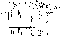
Figure 49-55 is generally with the 900 alternative vertical-type socket views that identify.Modular jack 900 is a kind of vertical socket, means that the perforate 902 of accepting plug is on the plane of a back 904 that is parallel to socket substantially, leaves socket so that be connected to printed circuit board (PCB) at this place's contact.Socket 900 comprises the contact on the position 1-8 that sequentially is positioned at socket, and similar and above-mentioned socket 250 and 700 with reference to Figure 11-16 and 37-42 description.
Figure 50 be among Figure 49 along the profile of 50-50 line, contact 910 is described.Contact 910 is in the position 3 and 5 in the modular jack 900.Contact 910 has a terminal 912 that engages wiring board.From terminal 912, contact 910 enters the back of contact carrier, and crooked about 90 degree form shank 914.The position of shank 914 is at the back edge standoff distance x1 from socket 900.Crooked then about 90 degree of contact 910 are to form shank 916, and this shank stops below front lip 214.
Figure 51 be among Figure 49 along the profile of 51-51 line, contact 920 is described.Contact 920 is in the position 1 and 7 in the modular jack 900.Contact 920 has a terminal 922 that engages wiring board.From terminal 922, contact 920 enters the back of contact carrier, and crooked about 90 degree form shank 924.The position of shank 924 is at the back edge standoff distance x2 from socket 900.Crooked then about 90 degree of contact 920 are to form shank 926, and this shank stops below front lip 214.Contact 920 in position 1 can be with have more flexible beryllium copper manufacturing than phosphor bronze contact.Some plug lacks contact in position 1 and 8, and is tending towards applying excessive power on the contact 1 and 8 of socket 900.When using this plug, the contact 920 usefulness beryllium copper manufacturings in the position 1 can prevent the distortion of contact in position 1.
Figure 52 be among Figure 49 along the profile of 52-52 line, contact 930 is described.Contact 930 is in the position 8 in the modular jack 900.Contact 930 has a terminal 932 that engages wiring board.From terminal 932, contact 930 enters the back of contact carrier, and crooked about 90 degree form shank 934.The position of shank 934 is at the back edge standoff distance x2 from socket 900.Crooked then about 90 degree of contact 930 are to form shank 936, and this shank stops below front lip 214.Contact 930 in position 8 can be with have more flexible beryllium copper manufacturing than phosphor bronze contact.Some plug lacks contact in position 1 and 8, and is tending towards applying excessive power at the contact 1 and 8 of socket 900.The beryllium copper manufacturing of contact in position 8 can prevent that contact is out of shape when using this class plug in position 1.
Figure 53 be among Figure 49 along the profile of 53-53 line, contact 940 is described.Contact 940 is in the position 2 in the modular jack 900.Contact 940 has a terminal 942 that engages wiring board.From terminal 942, contact 940 enters the back of contact carrier, and crooked about 90 degree form shank 944.The position of shank 944 is at the back edge standoff distance x1 from socket 900.Crooked then about 90 degree of contact 940 are to form shank 946, and this shank stops below front lip 214.
Figure 54 be among Figure 49 along the profile of 54-54 line, contact 950 is described.Contact 950 is in the position 4 and 6 in the modular jack 900.Contact 950 has a terminal 952 that engages wiring board.From terminal 952, contact 950 enters the back of contact carrier, and crooked about 90 degree form shank 954.The position of shank 954 is at the back edge standoff distance x2 from socket 900.Contact 950 bending is then spent to form shank 956 greater than 90, and this shank stops below front lip 214.
Typically, the contact in the socket 900 is arranged in pairs, and position 1 and 2 is defined as a pair ofly in other words, and position 3 and 6 is defined as a pair of, and position 4 and 5 is defined as a pair of, and position 7 and 8 is defined as a pair of.Figure 55 is for showing socket 900 rearviews of contact terminal.Shown in Figure 55, the position of contact terminal is on the various distances in socket edge.The position of terminal 912 is being separated by first apart from d1 from the modular jack shell rim.The position of terminal 922 is at the second distance d2 of being separated by from the modular jack shell rim.The position of terminal 932 is being separated by the 3rd apart from d3 from the modular jack shell rim.The position of terminal 942 is being separated by the 4th apart from d4 from the modular jack shell rim.The position of terminal 952 is being separated by the 5th apart from d5 from the modular jack shell rim.The separation of contact terminal reduce to and between cross-talk and improve performance.
Though have illustrated and described preferred embodiment, can make various modifications and substitute and without departing from the spirit and scope of the present invention to it.Correspondingly, be appreciated that the present invention is by graphic extension rather than is limited.
Claims (10)
1. modular jack comprises:
One has the housing of the perforate of accepting plug;
Described housing has the bottom and the back that is parallel to described perforate perpendicular to described perforate;
A plurality of contacts that are arranged in the described housing, described contact has the contact terminal, and this terminal is extended described bottom in addition so that be connected with printed substrate;
Described a plurality of contact comprises first contact, and this contact enters bottom and crooked 90 degree forming first shank, and in the first elbow bending greater than 90 degree but less than 180 degree to form second shank;
Described a plurality of contact comprises second contact, and this contact enters bottom and crooked 90 degree forming the 3rd shank, and in the second elbow bending greater than 90 degree but less than 180 degree to form the 4th shank;
Housing back first distance is being left in wherein said first elbow, and the described back of housing second distance is being left in second elbow, and described first distance is different from described second distance.
2. socket according to claim 1 is characterized in that:
Described contact arrangement is crossed over described socket in from one to eight position, and described first contact is in position one and described second contact is in position two.
3. as socket as described in the claim 2, it is characterized in that:
Extend the described contact terminal arrangement in addition of described bottom and become first row and second row, correspondence position one, three, five and seven contact terminal is drawn together in first package, and correspondence position two, four, six and eight contact terminal is drawn together in second package.
4. as socket as described in the claim 2, it is characterized in that:
The contact of the contact of described correspondence position one and described correspondence position two partners.
5. as socket as described in the claim 3, it is characterized in that:
The contact of the contact of described correspondence position three and described correspondence position six partners.
6. as socket as described in the claim 3, it is characterized in that:
The contact of the contact of described correspondence position four and described correspondence position five partners.
7. as socket as described in the claim 3, it is characterized in that:
The contact of the contact of described correspondence position seven and described correspondence position eight partners.
8. modular jack comprises:
One has the housing of the perforate of accepting plug;
Described housing has a back that is parallel to described perforate;
A plurality of contacts that are arranged in the described housing, described contact has the contact terminal, and this terminal is extended described back in addition so that be connected with printed substrate;
Described contact is arranged in pairs, first pair has first contact and second contact, second pair has the 3rd contact and the 4th contact, and the 3rd pair have the 5th contact and the 6th contact, the contact terminal of the described first and the 3rd contact is in the position from edge first distance of socket, the contact terminal of the described second and the 4th contact is in the position from the described edge of socket second distance, the contact terminal of described the 5th contact is in from the position of the described edge of socket the 3rd distance, and the contact terminal of described the 6th contact is in the position from the described edge of socket the 4th distance;
Described first distance, described second distance, described the 3rd distance and described the 4th distance have nothing in common with each other.
9. as socket as described in the claim 8, it is characterized in that, also comprise:
One the 4th pair has the 7th contact and the 8th contact, and the contact terminal of described the 7th contact is in the position from socket edge the 5th distance;
Described first distance, described second distance, described the 3rd distance, described the 4th distance and described the 5th distance have nothing in common with each other.
10. as socket as described in the claim 9, it is characterized in that:
The contact terminal of described the 8th contact is in the position from socket edge the 3rd distance.
Applications Claiming Priority (2)
| Application Number | Priority Date | Filing Date | Title |
|---|---|---|---|
| US09/499,509 US6361354B1 (en) | 1998-03-23 | 2000-02-07 | Vertical and right angle modular outlets |
| US09/499,509 | 2000-02-07 |
Publications (2)
| Publication Number | Publication Date |
|---|---|
| CN1451194A CN1451194A (en) | 2003-10-22 |
| CN1249864C true CN1249864C (en) | 2006-04-05 |
Family
ID=23985534
Family Applications (1)
| Application Number | Title | Priority Date | Filing Date |
|---|---|---|---|
| CNB018001823A Expired - Fee Related CN1249864C (en) | 2000-02-07 | 2001-02-06 | Vertical and right angle modular outlets |
Country Status (10)
| Country | Link |
|---|---|
| US (1) | US6361354B1 (en) |
| EP (1) | EP1221184B1 (en) |
| JP (1) | JP2003522389A (en) |
| CN (1) | CN1249864C (en) |
| BR (1) | BR0105560A (en) |
| CA (1) | CA2368573A1 (en) |
| MX (1) | MXPA01010073A (en) |
| RU (1) | RU2262170C2 (en) |
| TW (1) | TW474052B (en) |
| WO (1) | WO2001057968A2 (en) |
Families Citing this family (20)
| Publication number | Priority date | Publication date | Assignee | Title |
|---|---|---|---|---|
| US6802743B2 (en) * | 2000-09-29 | 2004-10-12 | Ortronics, Inc. | Low noise communication modular connector insert |
| US6896557B2 (en) | 2001-03-28 | 2005-05-24 | Ortronics, Inc. | Dual reactance low noise modular connector insert |
| US7172466B2 (en) * | 2001-04-05 | 2007-02-06 | Ortronics, Inc. | Dual reactance low noise modular connector insert |
| TW528229U (en) * | 2002-04-26 | 2003-04-11 | Yuan-Huei Peng | Golden pin supporting stand structure |
| US20040022015A1 (en) * | 2002-07-31 | 2004-02-05 | Rung-Hua You | Signal plug structure |
| GB2393858B (en) * | 2002-10-03 | 2004-12-22 | Brand Rex Ltd | Improvements in and relating to electrical connectors |
| US6830488B2 (en) * | 2003-05-12 | 2004-12-14 | Krone, Inc. | Modular jack with wire management |
| WO2007092578A2 (en) * | 2006-02-08 | 2007-08-16 | The Siemon Company | Modular plugs and outlets having enhanced performance contacts |
| US7530854B2 (en) * | 2006-06-15 | 2009-05-12 | Ortronics, Inc. | Low noise multiport connector |
| US7288001B1 (en) | 2006-09-20 | 2007-10-30 | Ortronics, Inc. | Electrically isolated shielded multiport connector assembly |
| US7485010B2 (en) * | 2007-06-14 | 2009-02-03 | Ortronics, Inc. | Modular connector exhibiting quad reactance balance functionality |
| USD612856S1 (en) | 2008-02-20 | 2010-03-30 | Vocollect Healthcare Systems, Inc. | Connector for a peripheral device |
| USD615040S1 (en) | 2009-09-09 | 2010-05-04 | Vocollect, Inc. | Electrical connector |
| US8262403B2 (en) | 2009-09-10 | 2012-09-11 | Vocollect, Inc. | Break-away electrical connector |
| US8241053B2 (en) * | 2009-09-10 | 2012-08-14 | Vocollect, Inc. | Electrical cable with strength member |
| DE102010014294A1 (en) * | 2010-04-08 | 2011-10-13 | Phoenix Contact Gmbh & Co. Kg | Contact field for connectors |
| US8647146B2 (en) | 2011-01-20 | 2014-02-11 | Tyco Electronics Corporation | Electrical connector having crosstalk compensation insert |
| US8591248B2 (en) * | 2011-01-20 | 2013-11-26 | Tyco Electronics Corporation | Electrical connector with terminal array |
| RU2537955C1 (en) * | 2013-07-09 | 2015-01-10 | Федеральное государственное бюджетное образовательное учреждение высшего профессионального образования "Ульяновский государственный технический университет" | Device to start and compensate for reactive power of induction motor |
| US9722380B1 (en) * | 2016-07-22 | 2017-08-01 | Rockwell Automation Technologies, Inc. | Network distribution adapter for a motor control center |
Family Cites Families (13)
| Publication number | Priority date | Publication date | Assignee | Title |
|---|---|---|---|---|
| US4292736A (en) | 1978-09-08 | 1981-10-06 | Amp Incorporated | Method for making jack type receptacles |
| JPS6286676A (en) | 1985-10-11 | 1987-04-21 | ヒロセ電機株式会社 | Electric connector receptacle and manufacture of the same |
| NL9000721A (en) * | 1990-03-27 | 1991-10-16 | Du Pont Nederland | TWO-PART RECORD CONTACT UNIT FOR A MODULAR PATCH ASSEMBLY. |
| US5387135A (en) * | 1993-06-09 | 1995-02-07 | Apple Computer, Inc. | Special purpose modular receptacle jack |
| US5639266A (en) * | 1994-01-11 | 1997-06-17 | Stewart Connector Systems, Inc. | High frequency electrical connector |
| US5791942A (en) | 1994-01-11 | 1998-08-11 | Stewart Connector Systems, Inc. | High frequency electrical connector |
| EP0674364B1 (en) | 1994-03-26 | 1999-11-24 | Molex Incorporated | Modular jack type connector |
| US5456619A (en) * | 1994-08-31 | 1995-10-10 | Berg Technology, Inc. | Filtered modular jack assembly and method of use |
| US5599209A (en) * | 1994-11-30 | 1997-02-04 | Berg Technology, Inc. | Method of reducing electrical crosstalk and common mode electromagnetic interference and modular jack for use therein |
| US5779503A (en) | 1996-12-18 | 1998-07-14 | Nordx/Cdt, Inc. | High frequency connector with noise cancelling characteristics |
| US6012953A (en) | 1997-08-05 | 2000-01-11 | 3Com Corporation | Surface mountable electrical connector system |
| US6083052A (en) * | 1998-03-23 | 2000-07-04 | The Siemon Company | Enhanced performance connector |
| US6086428A (en) | 1998-03-25 | 2000-07-11 | Lucent Technologies Inc. | Crosstalk compensation for connector jack |
-
2000
- 2000-02-07 US US09/499,509 patent/US6361354B1/en not_active Expired - Fee Related
-
2001
- 2001-02-06 CA CA002368573A patent/CA2368573A1/en not_active Abandoned
- 2001-02-06 EP EP01925081A patent/EP1221184B1/en not_active Expired - Lifetime
- 2001-02-06 BR BR0105560-7A patent/BR0105560A/en not_active IP Right Cessation
- 2001-02-06 WO PCT/US2001/040042 patent/WO2001057968A2/en active Application Filing
- 2001-02-06 JP JP2001557121A patent/JP2003522389A/en active Pending
- 2001-02-06 CN CNB018001823A patent/CN1249864C/en not_active Expired - Fee Related
- 2001-02-06 MX MXPA01010073A patent/MXPA01010073A/en active IP Right Grant
- 2001-02-06 RU RU2001130056/09A patent/RU2262170C2/en not_active IP Right Cessation
- 2001-02-07 TW TW090102617A patent/TW474052B/en not_active IP Right Cessation
Also Published As
| Publication number | Publication date |
|---|---|
| US6361354B1 (en) | 2002-03-26 |
| EP1221184A2 (en) | 2002-07-10 |
| CN1451194A (en) | 2003-10-22 |
| RU2262170C2 (en) | 2005-10-10 |
| CA2368573A1 (en) | 2001-08-09 |
| EP1221184B1 (en) | 2009-12-30 |
| MXPA01010073A (en) | 2002-05-06 |
| WO2001057968A2 (en) | 2001-08-09 |
| WO2001057968A3 (en) | 2002-03-21 |
| BR0105560A (en) | 2002-03-19 |
| JP2003522389A (en) | 2003-07-22 |
| TW474052B (en) | 2002-01-21 |
Similar Documents
| Publication | Publication Date | Title |
|---|---|---|
| CN1249864C (en) | Vertical and right angle modular outlets | |
| CN1138318C (en) | Enhanced performance connector | |
| CN1301573C (en) | Connector assembly | |
| CN1930746A (en) | Methods and apparatus for reducing crosstalk in electrical connectors | |
| CN1129978C (en) | Modular electrical connector assemblies with magnetic filter and/or visual indicator | |
| CN1108651C (en) | Combined connector with DC decoupling and filtering device | |
| CN1315233C (en) | High-density connector assembly with bending ability | |
| US8267714B2 (en) | Modular connector with reduced termination variability and improved performance | |
| CN1292601C (en) | Jack assembly | |
| CN1282455A (en) | High frequency bi-level offset multi-port jack | |
| CN1739223A (en) | High-density connector assembly with tracking ground structure | |
| CN1650482A (en) | High-speed differential signal connector | |
| CN1835300A (en) | Connector for data transmission via electrical wires | |
| CN1685565A (en) | Plug-in connector for a connector-ended cable | |
| CN1515051A (en) | Matrix connector with integrated power contacts | |
| CN1170254A (en) | Telecommunications connectors | |
| CN1976125A (en) | Connector | |
| US6368144B2 (en) | Enhanced performance modular outlet | |
| CN1783586A (en) | Multi-pole coaxial cable connector and connector assembling method | |
| CN101036270A (en) | Connector | |
| CN1249856A (en) | Enhanced performance telecommunications connector | |
| CN1066861C (en) | Shielded data connector | |
| CN1134862C (en) | Modular electrical plug and plug-cable assembling including the same | |
| KR100549739B1 (en) | A Modular jack and cable connection method using thereof |
Legal Events
| Date | Code | Title | Description |
|---|---|---|---|
| C06 | Publication | ||
| PB01 | Publication | ||
| C10 | Entry into substantive examination | ||
| SE01 | Entry into force of request for substantive examination | ||
| C14 | Grant of patent or utility model | ||
| GR01 | Patent grant | ||
| C17 | Cessation of patent right | ||
| CF01 | Termination of patent right due to non-payment of annual fee |
Granted publication date: 20060405 Termination date: 20140206 |