CN1249460A - Digitalization apparatus with out-of-bound tracking function - Google Patents
Digitalization apparatus with out-of-bound tracking function Download PDFInfo
- Publication number
- CN1249460A CN1249460A CN99118092A CN99118092A CN1249460A CN 1249460 A CN1249460 A CN 1249460A CN 99118092 A CN99118092 A CN 99118092A CN 99118092 A CN99118092 A CN 99118092A CN 1249460 A CN1249460 A CN 1249460A
- Authority
- CN
- China
- Prior art keywords
- indicator
- graphic tablet
- borderline region
- effective coverage
- coordinate
- Prior art date
- Legal status (The legal status is an assumption and is not a legal conclusion. Google has not performed a legal analysis and makes no representation as to the accuracy of the status listed.)
- Pending
Links
Images


Classifications
-
- G—PHYSICS
- G06—COMPUTING; CALCULATING OR COUNTING
- G06F—ELECTRIC DIGITAL DATA PROCESSING
- G06F3/00—Input arrangements for transferring data to be processed into a form capable of being handled by the computer; Output arrangements for transferring data from processing unit to output unit, e.g. interface arrangements
- G06F3/01—Input arrangements or combined input and output arrangements for interaction between user and computer
- G06F3/03—Arrangements for converting the position or the displacement of a member into a coded form
- G06F3/041—Digitisers, e.g. for touch screens or touch pads, characterised by the transducing means
- G06F3/046—Digitisers, e.g. for touch screens or touch pads, characterised by the transducing means by electromagnetic means
-
- F—MECHANICAL ENGINEERING; LIGHTING; HEATING; WEAPONS; BLASTING
- F21—LIGHTING
- F21S—NON-PORTABLE LIGHTING DEVICES; SYSTEMS THEREOF; VEHICLE LIGHTING DEVICES SPECIALLY ADAPTED FOR VEHICLE EXTERIORS
- F21S6/00—Lighting devices intended to be free-standing
- F21S6/002—Table lamps, e.g. for ambient lighting
-
- F—MECHANICAL ENGINEERING; LIGHTING; HEATING; WEAPONS; BLASTING
- F21—LIGHTING
- F21V—FUNCTIONAL FEATURES OR DETAILS OF LIGHTING DEVICES OR SYSTEMS THEREOF; STRUCTURAL COMBINATIONS OF LIGHTING DEVICES WITH OTHER ARTICLES, NOT OTHERWISE PROVIDED FOR
- F21V1/00—Shades for light sources, i.e. lampshades for table, floor, wall or ceiling lamps
- F21V1/14—Covers for frames; Frameless shades
- F21V1/16—Covers for frames; Frameless shades characterised by the material
- F21V1/20—Covers for frames; Frameless shades characterised by the material the material being glass
-
- F—MECHANICAL ENGINEERING; LIGHTING; HEATING; WEAPONS; BLASTING
- F21—LIGHTING
- F21V—FUNCTIONAL FEATURES OR DETAILS OF LIGHTING DEVICES OR SYSTEMS THEREOF; STRUCTURAL COMBINATIONS OF LIGHTING DEVICES WITH OTHER ARTICLES, NOT OTHERWISE PROVIDED FOR
- F21V33/00—Structural combinations of lighting devices with other articles, not otherwise provided for
- F21V33/0004—Personal or domestic articles
- F21V33/0024—Household or table equipment
- F21V33/0028—Decorative household equipment, e.g. plant holders or food dummies
-
- G—PHYSICS
- G06—COMPUTING; CALCULATING OR COUNTING
- G06F—ELECTRIC DIGITAL DATA PROCESSING
- G06F3/00—Input arrangements for transferring data to be processed into a form capable of being handled by the computer; Output arrangements for transferring data from processing unit to output unit, e.g. interface arrangements
- G06F3/01—Input arrangements or combined input and output arrangements for interaction between user and computer
- G06F3/048—Interaction techniques based on graphical user interfaces [GUI]
- G06F3/0487—Interaction techniques based on graphical user interfaces [GUI] using specific features provided by the input device, e.g. functions controlled by the rotation of a mouse with dual sensing arrangements, or of the nature of the input device, e.g. tap gestures based on pressure sensed by a digitiser
- G06F3/0488—Interaction techniques based on graphical user interfaces [GUI] using specific features provided by the input device, e.g. functions controlled by the rotation of a mouse with dual sensing arrangements, or of the nature of the input device, e.g. tap gestures based on pressure sensed by a digitiser using a touch-screen or digitiser, e.g. input of commands through traced gestures
-
- F—MECHANICAL ENGINEERING; LIGHTING; HEATING; WEAPONS; BLASTING
- F21—LIGHTING
- F21W—INDEXING SCHEME ASSOCIATED WITH SUBCLASSES F21K, F21L, F21S and F21V, RELATING TO USES OR APPLICATIONS OF LIGHTING DEVICES OR SYSTEMS
- F21W2121/00—Use or application of lighting devices or systems for decorative purposes, not provided for in codes F21W2102/00 – F21W2107/00
Abstract
A digitizer tablet includes an active area as well as border area(s) which are adjacent to and/or surround the active area. Useful coordinate data (e.g. coordinate data as to only one of the x and y directions) of a pointer taken from border areas is reported to a corresponding computer and/or display screen as if the coordinate data was taken or near at the edge of the active area on the tablet. This effectively enlarges the surface area on the tablet which may be utilized by a user to select scroll items, menu items, and other selectable areas which appear at or near edges of the corresponding display screen.
Description
The present invention relates to a kind of digitizer devices and methods therefor, detected positional information when it can utilize indicator (for example stylus, mouse or punck device) outside it is positioned at digitizer graphic tablet effective coverage.The present invention is specifically related to a kind of digitizer devices and methods therefor, is used for being reported in the detected indicator coordinate of borderline region outside the graphic tablet effective coverage, these coordinates just look like in the effective coverage or its edge on detected the same.This makes and near the optional outer peripheral areas that occurs as the edge at corresponding display screen can corresponding amplification on the digitizer graphic tablet therefore the user can more easily be selected.
Known in the prior art is that the digitizer graphic tablet is used for to corresponding computer display input information.For example, referring to the 4th, 878,553,5,028,745,5,793, No. 360 disclosed contents of United States Patent (USP), it is for reference to list these documents at this.Also can be 09/105,217 the disclosed content of U.S. Patent application referring to the sequence number of submitting on June 26th, 1998, it be for reference to list the document at this.Above-mentioned digitizer makes its artist's grade of figure write (for example mobile digitized instrument indicator is drawn a picture or written character) on corresponding display.
Usually, the digitizer graphic tablet intercoms mutually with corresponding calculated machine display, and its effect is as follows.The user handles (promptly moving) indicator by graphic tablet, and for example stylus, mouse or punck device make the cursor of on display shape such as arrow or the device of using a sand filter for marking the hours move with indicator.Cursor shown on the display is identical with indicator residing position on graphic tablet in residing position on the screen.For example, if the user makes indicator be in the central authorities of digitizer graphic tablet, so corresponding cursor also is in the central authorities of display.Equally, if the user makes indicator be in the lower left corner of graphic tablet, then cursor is located in the lower left corner of display.Want on display moving cursor, choice menus or roll, correspondingly will be respectively on graphic tablet mobile indicator or click pointer device.
The digitizer graphic tablet comprises an effective coverage, in this zone, determine coordinate data or position (be x, y coordinate) of indicator on graphic tablet with quite high degree of accuracy at least.Outside this effective coverage, can not determine the x of indicator on graphic tablet with high like this degree of accuracy, the y position.Therefore, in conventional digitizer, when judging indicator outside predetermined effective coverage the time, graphic tablet is no longer reported coordinate data, and the cursor on corresponding display screen can not move with indicator.
In some digitizer, the effective coverage of graphic tablet comprises an array x direction lead and an array y direction lead (x is vertical mutually with the y lead) under the working face that is in graphic tablet.Be used to signal message,, determine the position (for example aforesaid United States Patent (USP) 4,878,553 and 5,028,745) of indicator on graphic tablet by between the adjacent wires on x and/or the y direction, carrying out interpolation from several parallel wires.Yet, near the edge or borderline region of x and/or y wire array, there is such position, promptly there are not enough leads to carry out interpolation so that on x and y both direction, reach desired predetermined accuracy.So such edge or borderline region just have been in outside the effective coverage of graphic tablet, and generally can not be used for determining and the accurately x of report indicator on graphic tablet the y coordinate position.
Many application programs (as the Word Word and the Excel electronic report forms software of Microsoft) are arranged for the user provides the scroll bar that is positioned at the display screen right side, like this user just can be in particular document or file scroll-up/down.Usually, scroll bar can comprise and contains first blockage to upward arrow, contains second blockage of a downward arrow and at slidably the 3rd blockage between first blockage and second blockage on the scroll bar.The 3rd blockage has been indicated the relative position of the current display part of on display document or file with respect to the whole length of document/file.In order upwards to roll, the user is steering indicator on the digitizer graphic tablet, until corresponding light on the display screen is marked have now on first blockage of upward arrow or in, then, the user uses the side switch, press contact-making switch etc. clicks indicator.This click, it is the same to hit mouse with regard to image point, makes to begin to scroll up in a kind of known mode.According to similar mode, the user selects or clicks second blockage with downward arrow and can roll downwards.Usually, this rolling is carried out line by line.In order to roll page by page or line scrolling, the user can click first and third party's piece between scroll bar scroll up, or second and third party's piece between scroll bar roll downwards.In order to roll, the user also can place the cursor of display screen third party's piece, on corresponding to the zone on the graphic tablet of third party's piece, click indicator and keep the click state, by moving up and down indicator (third party's piece), with the current display part of up-down adjustment document/file.After the desired part that arrives document/file, the user removes the click state of this indicator.
When general digitizer graphic tablet uses with these application programs or operating system, be positioned at the narrow scroll bar of computer display right side edge position, corresponding near on the right side edge of graphic tablet effective coverage or corresponding narrow zone.So the user is in order to roll on display, it must place indicator this near in the narrow zone or square at edge, graphic tablet effective coverage.For example, if use one the 4 inches graphic tablets (being less than display screen generally speaking) of taking advantage of 5 inches, then two little rolling squares can be very little, and very difficult location indicator.Because rolling square undersized, the user taken long to indicator is positioned in the rolling square and/or menu square zone on the graphic tablet.Then, the user also will keep the click state of indicator in this zonule.Except losing time, this also can make the user click undesirable square or project sometimes.
In addition, utilizing the 3rd or sliding-rolling square when rolling, the user must be on graphic tablet vertical moving indicator in this little band of effective coverage, if graphic tablet report indicator has left the graphic tablet effective coverage, to stop to roll, the user has to require again third party's piece to continue to roll.Therefore, the zone that can be used for rolling on the graphic tablet is too little.
The 4th, 992, No. 630 U.S. Patent Publications a kind of digitizer graphic tablet, it has the menu that is positioned at the border area on the graphic tablet electrod-array nonlinear boundary.But the graphic tablet of the 4th, 992, No. 630 United States Patent (USP)s does not have to solve the problem that proposes above.The 4th, 992, in No. 630 United States Patent (USP)s, menu area is used to change distance and pressure threshold.Yet, the 4th, 992, in No. 630 United States Patent (USP)s, when on display, writing or during option, the user can not utilize menu area to report the indicator coordinate information.Specifically, the 4th, 992, in No. 630 United States Patent (USP)s, do not export the coordinate of menu area, determining, but adopted these coordinates to adjust the parameter of signal processing circuit from graphic tablet, see also United States Patent (USP) the 4th hurdle the 44th to 49 row the 4th, 992, No. 630.During another problem of the system of the 4th, 992, No. 630 United States Patent (USP)s, it needs indicator physically to be connected to graphic tablet.In addition, the linear/non-linear technology of the 4th, 992, No. 630 United States Patent (USP)s is unsuitable for the digitizer of some common type.
In addition, many operating systems (as the MACOS8 of Apple, the Windows ' 95 of Microsoft or NT 4) have the certain menu function button that is positioned at the display screen edge.In Windows operating system, " taskbar " can be set for " hiding automatically ", when the user did not re-use it, it can disappear from display screen.In order to make " taskbar " turn back to screen from its " hiding ground ", the user must place screen cursor on the edge of display screen just.Digitizer for routine, the user visits the taskbar of hiding automatically not too easily, because the user has to want just indicator to be placed on the edge of screen, screen edge is represented by the little capable picture element along edge, graphic tablet effective coverage usually.
Another problem of conventional digitizer is, when indicator when fast dot-dash is to the edge of effective coverage on graphic tablet, usually on corresponding display screen, do not demonstrated display screen edge (being that dot-and-dash line stops in distance display screen edge/boundary) nearby.This is because according to dot-dash speed, the quick dot-dash operation of some of indicator may only have per approximately 1.5 inches reports indicator coordinate once.So, when near the edge of conventional graphic tablet, the user need slowly write or draw, so that the graphic tablet report is near the pointer co-ordinate data at edge, effective coverage, pointer co-ordinate data or line like this (for example stroke) can not stop at 0.5 inch place of distance display screen or edge, effective coverage.This problem of bringing is that user's dot-dash naturally writes on graphic tablet/draws.For example, the artist usually wishes quick indicator dot-dash operation.
Obviously as can be seen, have a kind of demand in the art from above-mentioned discussion, Here it is, makes the zonule on the easier selection corresponding computer of the digitizer graphic tablet user display screen, as scroll bar/square, menu item or the like.Also have another kind of demand in the art, that is exactly, and can be used for being chosen on the edge/boundary of corresponding display screen on the expanding digital instrument graphic tablet or the appropriate section of menu item, rolling square/bar and other option of near appearance.Also have another kind of demand in the art, that is exactly to make the user operate in the edge that always is shown to display screen on the respective display at the indicator dot-dash that carries out fast on the graphic tablet.
Other demand for conspicuous for those of ordinary skills present technique field after the demand that satisfies above-mentioned present technique field and the disclosure below providing has proposed the present invention.
An object of the present invention is, the zone on the expanding digital instrument graphic tablet, can place in this zone that indicator (as stylus, mouse and punck device) is selected to be positioned on the edge of corresponding display screen or the border or near project or zone.
Another object of the present invention is, the respective regions of expansion on the digitizer graphic tablet, can place in this zone that indicator is selected to be positioned on the edge of corresponding display screen or the border or near scroll bar/square or menu item.
Another purpose of the present invention is, at least to corresponding calculated machine or display report/output outside the graphic tablet effective coverage the border or outer peripheral areas in some pointer co-ordinate data of detecting, these coordinate datas just look like to obtain near the edge of graphic tablet effective coverage or detected the same, thereby have enlarged the respective regions that can be used on the graphic tablet is chosen near the project that occurs the display edge.
A further object of the present invention is, to the report/output of corresponding calculated machine outside the graphic tablet effective coverage the border or outer peripheral areas in the pointer co-ordinate data obtaining or detect, these coordinate datas just look like detected the same on the edge of graphic tablet effective coverage, thereby enlarged the Free Region on the graphic tablet effectively, the quick dot-dash operation that the user is carried out on graphic tablet can expand to the edge of display screen always.
Say that generally the present invention has satisfied the demand in the art by a kind of method of using the digitizer graphic tablet is provided, this method comprises the following steps:
A kind of digitizer graphic tablet is set, and it comprises that an effective coverage and at least one are outside the effective coverage but the borderline region adjacent with the effective coverage;
A display is set, and it is communicated by letter with the digitizer graphic tablet when work;
An indicator is set, and the user handles it on described graphic tablet;
Mobile indicator on described graphic tablet, described graphic tablet detect the coordinate information of described indicator with respect to described graphic tablet;
According to the move mode of described indicator on described graphic tablet, moving cursor or draw a line on described display; And
On described display, utilize some detected pointer co-ordinate data on borderline region at least, detected in described effective coverage as detected described pointer co-ordinate data in described borderline region.
By specific embodiment the present invention is described below with reference to accompanying drawings, in the accompanying drawing:
Fig. 1 is the functional block diagram of expression one embodiment of the invention, wherein, has inserted graphic tablet driver, operating system and application program in computing machine, and by these programs, digitizer graphic tablet and indicator can communicate;
Fig. 2 is the electrical schematic diagram of the digitizer graphic tablet circuit of Fig. 1, and it is illustrated in the graphic tablet respectively the overlapping coil along x and the expansion of y direction;
Fig. 3 is the skeleton view of the stylus indicator of Fig. 1 of using of the digitizer graphic tablet with Fig. 2;
Fig. 4 illustrates the conditioned circuit of wiping frequency that nib sends out of phase of wiping that is used to make Fig. 3 stylus of specific embodiment of the present invention;
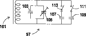
Fig. 5 illustrate specific embodiment of the present invention be used to make the nib of writing of Fig. 3 stylus send the different tuned circuits of writing frequency and phase place;
Fig. 6 is the top view of digitizer graphic tablet of the embodiment of Fig. 1 to 5 of the present invention, and the menu bar zone is wherein arranged on the graphic tablet, can come the choice menus item by steering indicator in this zone;
Fig. 7 illustrates the position in the peripheral boundary zone adjacent with the effective coverage of graphic tablet Fig. 1 to 2 the embodiment of the invention;
Fig. 8 is illustrated in the Windows that shows on the graphoscope
TM/ Microsoft Word
TMScreen has a scroll bar and a plurality of rolling square on the right side of this screen of close screen edge, adopts some embodiment of the present invention can more easily select these scroll bar/squares;
Fig. 9 illustrates the screen of Windows ' 95 (98 or NT), near this screen left side edge a plurality of icons is arranged, and adopts the embodiment of the invention can more easily select these icons;
Figure 10 shows the screen of Windows, along a plurality of projects are arranged on the taskbar at this top of screen edge, adopts the embodiment of the invention can more easily select these projects; If taskbar is arranged to hide automatically, then adopts embodiments of the invention can more easily show this taskbar;
Figure 11 illustrates the screen of Windows ' 95 (98 or NT), near the taskbar this screen left side edge a plurality of icons and project is arranged, and adopts the embodiment of the invention can more easily select these icons and project; If taskbar is arranged to hide automatically, then adopts embodiments of the invention can more easily show this taskbar;
Figure 12 shows the screen of Windows, on the taskbar of (this is the default position of Windows ' 95 taskbars) a plurality of selectable items is arranged near this bottom of screen edge, adopts the embodiment of the invention can more easily select these projects; If taskbar is arranged to hide automatically, then adopts embodiments of the invention can more easily show this taskbar;
Figure 13 illustrate displaying-with the display screen that may be compared-adopt the drawn line (as dot-and-dash line) of the digitizer graphic tablet of the embodiment of the invention by the possible conventional digitizer dot-and-dash line of brachymemma; And
Figure 14 illustrates the display screen of a control panel of expression, and the user can use this control panel to change certain part of display screen, the corresponding or coincidence in effective coverage of this part and the digitizer graphic tablet of just communicating by letter with display.
Be described more specifically now with reference to accompanying drawing, identical label is represented identical parts in each accompanying drawing.
The digitizer system of the specific embodiment of the invention comprises: graphic tablet, indicator and have the corresponding computer of display.In case detect indicator moving on graphic tablet, then correspondingly cursor moves or the line that draws on graphoscope.This makes the user by using graphic tablet and indicator can work on computers (for example draw, write etc.).
Respective regions on Regional Representative's display on the graphic tablet.Therefore, in case indicator is put into the lower left corner, and the lower right corner of graphic tablet of laterally moving right from here of graphic tablet on graphic tablet, will on display, draw one from the display lower left corner along display to the line segment in the corresponding lower right corner of display (or cursor moves to the lower right corner from the display lower left corner).
According to specific embodiments of the invention, acquisition/detected coordinate in the borderline region of electronic director (as stylus, mouse and punck device etc.) on graphic tablet outside the effective coverage, reported or exported to corresponding computer or display, in effective coverage (as at hithermost neighboring edge place), obtained as these coordinates.Like this, just enlarged the Free Region of digitizer graphic tablet, also corresponding expansion corresponding to the border of corresponding display screen or the graphic tablet zone at edge.Therefore, the user can select at an easy rate (click) on the display screen edge or near appearance project (for example, menu item, scroll bar/square, startup square etc.), this is because the respective regions on the graphic tablet is bigger than of the prior art, so the corresponding selectable items zone that occurs on the display that enlarged.
With respect to other graphic tablet zone in the graphic tablet effective coverage, also corresponding extended corresponding to the graphic tablet zone of display border or periphery.
According to another embodiment of the present invention or purposes, the pointer co-ordinate data that will in border outside the graphic tablet effective coverage or outer peripheral areas, obtain (x and/or y indicator coordinate), report or export to corresponding computer and/or display, as they on the edge of graphic tablet effective coverage or near acquisition, so the quick indicator dot-dash that the user carries out on graphic tablet can extend to the edge of display always.
According to another embodiment of the present invention, the pointer co-ordinate data that graphic tablet will obtain in border outside the graphic tablet effective coverage or outer peripheral areas, the report or export to corresponding computer and/or display, in fact laterally or vertically expanded to such degree as graphic tablet.Then, in the driver of operating system (OS), shear these coarse coordinates, so just can use the coordinate data of borderline region report to determine along the edge of display screen or the position of the indicator on the edge.This is similar to previous embodiment effect, and difference is that the shearing of the coordinate data of borderline region is carried out in driver or OS, rather than realizes in graphic tablet processor firmware.
Fig. 1 be the expression embodiment of the invention the exemplary numbers instrument system functional block diagram.This figure schematically shows the function of the CPU realization of computing machine 1.Can use software or hardware to be implemented in the various functions of this description or displaying.
When detection coordinates, digitizer graphic tablet 15 is wanted the position of detected electrons indicator (stylus 17 and/or mouse/punck device 19) and the respective switch state of indicator.Digital code signal by mailing to graphic tablet from indicator or by change from indicator mail to graphic tablet simulating signal frequency or change its phase place, each indicator is to the on off state of graphic tablet circular indicator.Be used to use graphic tablet 15 and computing machine 1 to detect the position of indicating equipment 17 and 19 and the exemplary method and the system of on off state, be disclosed in the 4th, 878,553,5,028,745 and 4,999, No. 461 United States Patent (USP)s and sequence number are 08/388,265 and 08/352,133 U.S. Patent application, it is for reference to list these documents at this.By the switch on the steering indicator, the user can be by being positioned at indicator the corresponding region on the graphic tablet 15 and starting corresponding selector marker switch, choice menus item, roll item or other project on display 9.
The manufacturer of equipment 15 generally will provide graphic tablet driver 5 for the user.Driver 15 is usually programs that (by as floppy disk or CD) installs in computing machine 1, is used for coordinate information, switching information and other detailed information of graphic tablet 15 are sent to the OS3 or the application program 7 of application-interface layer (API).This transmission comprises that not only the active transmission of data also comprises passive transmission, and the latter makes program 7 or the like obtain data.Because these three programs are software or firmware, so can adopt the partial function of each program in these three programs in other program.The repertoire that for example, in program 7, can comprise driver 5.
When operator or user by wipe/when write indicator 17,19 was carried out the coordinates input, the operator wanted content displayed on the visual examination display 9.Interactive input mainly is subjected to the control of program 7.Be input as example with indicator in the graphic processor (CAD), if indicated position is in drawing or in the perform region of graphic tablet 15, then program 7 will represent that the designator cursor of shape such as arrow or cross (for example, by) of this indicating positions is presented on the display screen 9.Certainly, on display screen 9, also can adopt the cursor of other shape.
Fig. 2 illustrates the circuit of digitizer graphic tablet 15, and graphic tablet 15 is used for x, the y indicator coordinate figure of indicator 17,19 positions on the test pattern tablet 15.As shown in the drawing, in the plate body of digitizer graphic tablet, be provided with an array x direction lead and an array y direction lead, wherein x becomes approximate orthogonality relation each other with y direction lead.In the embodiment of Fig. 2, x direction position detecting system comprises a plurality of parallel overlapping conductive coil 24-30 (comprising 26 ' and 28 '), and y direction position detecting system comprises a plurality of parallel overlapping conductive coil 31-42.In certain embodiments, coil 24-30 can detect the electromagnetic wave from indicator on the x direction, be the position of indicator on the x direction, and coil 24-30 can detect the electromagnetic wave from indicator on the y direction, i.e. the position of indicator on vertical or y direction.Like this, just obtained indicator coordinate position (x, y).Though Fig. 2 shows the overlapping coil of concrete number on x and y all directions, it will be understood by those skilled in the art that and can the overlapping coil of any number be set according to the size of graphic tablet, desired indicator post detection resolution on all directions.
Still referring to Fig. 2, graphic tablet 15 also comprises the display 9 that the x direction selects circuit 45, y direction to select circuit 47, x direction connection on-off circuit 49, y direction connection on-off circuit 51, x direction transtation mission circuit 53, y direction transtation mission circuit 55, x direction receiving circuit 57, y direction receiving circuit 59, graphic tablet treatment facility 61 (processor chips and/or the computer chip that for example, comprise firmware), graphic tablet to communicate with by computing machine.In the embodiment shown in Figure 2, x direction coil 24-30 and y direction coil 31-42 all alternately work under electromagnetic wave transmission and Electromagnetic Wave Detection pattern, so that the tuned circuit in electromagnetic wave generation pattern in indicator is powered, and under the Electromagnetic Wave Detection pattern, detect the position of indicator.For example, referring to the embodiment in the instructions of aforesaid United States Patent (USP) 5,028,745, it is for reference to list the document at this.
Certainly, in other embodiments of the invention, when indicator during near graphic tablet, x direction coil can send electromagnetic wave to indicator continuously, y direction coil can continuous detecting from the electromagnetic wave of indicator tuned circuit, vice versa.Like this, just can determine the position of indicator on graphic tablet, and can omit connection on-off circuit 49 and 51.
In Fig. 2, the effective coverage of the outline line presentation graphic tablet of label 65 indications.In effective coverage 65, can detect indicator 17,19 in the x of two quadratures and the position on the y direction with predetermined precision.For example in effective coverage 65, can with on x and y both direction at least about per inch 1000 lines (1pi)-2000lpi (better), be at least about 2500lpi-resolution (best), detect the position of indicator on x and y both direction.In different embodiments of the invention, the detection resolution in the effective coverage 65 on x and y both direction can be the same or different.Owing to carrying out interpolation between the adjacent windings on x and/or the y direction, so in effective coverage 65, can obtain such indicator post resolution.For example, can with the signal combination that detects by 3 to 5 adjacent windings to the substitution interpolation algorithm in, determine the accurate position of indicator when indicator is between adjacent windings, as aforesaid U.S. Patent 4,878,553,5,028,745 is disclosed, and it is for reference to list these documents at this.Also can be referring to the 4th, 999, No. 461 United States Patent (USP)s, it is for reference to list the document at this.For correct interpolation, may need to make indicator near a plurality of coils.
Yet, beyond effective coverage 65, can not with the effective coverage in same precision determine the position of indicator on x and y both direction.This is owing to all there be not enough coils to satisfy the requirement of the interpolation that obtains this precision near the indicator on this both direction.For example, if indicator in the effective coverage beyond 65 and be positioned at the position 67 on 65 right sides, effective coverage, then vertical or y trafficator position still can utilize y direction coil 31-42 to detect with precision same in approximate and the effective coverage 65.Yet, when indicator is in position 67, can not on the x direction, obtain the indicator post of aforementioned predetermined accuracy, because near indicator, have only the coil (for example, coil 24 and 30) of one or two x direction.Owing near indicator, have only the coil of two x directions, thus interpolation algorithm can not export on the x direction with indicator for example near the indicator post of the identical desired precision of precision when three to five coils are arranged.So, in the borderline region 69 adjacent with the right hand edge of effective coverage 65, indicator post accuracy of detection on the x direction is less than x directional precision in the effective coverage 65 (but the indicator post accuracy of detection on the y direction remains unchanged basically, does not perhaps resemble serious deterioration the x directional precision) relatively.Situation also is like this in the borderline region 71 in 65 left sides, effective coverage.Yet in each borderline region 73 and 75 of the top of effective coverage and bottom, the precision on the y direction is less than the precision in the effective coverage 65 relatively, and x trafficator accuracy of detection keeps the same with in effective coverage 65 time basically.
Therefore, in the borderline region 69 and 71 outside effective coverage 65, y trafficator coordinate data still has certain precision comparatively speaking and is available, yet x direction coordinate data but is not like this.Similarly, in the adjacent boundary zone 73 and 75 outside effective coverage 65, x trafficator coordinate data still has certain precision comparatively speaking and is available, yet y direction coordinate data but is not like this.Like this, in certain embodiments, the x trafficator data in graphic tablet output boundary zone 73 and 75, and it is presented on the display 9, as these data near the edge, effective coverage or obtain on the edge.And in some embodiments, the y directional data in graphic tablet output boundary zone 69 and 71, and it is presented on the display 9, as these data near the edge, effective coverage or obtain on the edge.
Fig. 7 illustrates the borderline region 69,71,73 and 75 positions with respect to effective coverage 65 of certain embodiments of the invention, wherein can be according to the required size and dimension that should be used for regulating each borderline region.In certain embodiments of the present invention, the shape of borderline region 69-75 preferably strip and position near adjacent effective coverage 65 ( borderline region 73 and 75 is parallel to each other, and borderline region 69 and 71 is parallel to each other).
According to some embodiment of the present invention, graphic tablet (by the firmware/processor in the graphic tablet 61) is to computing machine 1 and/or display 9 outputs detected pointer co-ordinate data in one or more borderline regions 69,71,73 and 75, as these coordinate datas on the edge of the effective coverage 65 of next-door neighbour's pointer detection position or near acquisition.So, for example with reference to Fig. 2 and Fig. 7, graphic tablet will be in the accurate relatively y direction coordinate data output of position 67 place's indicators in the borderline region 69 and report to computing machine by firmware wherein, obtain on 65 edges, effective coverage of this y direction coordinate data at 77 places, position.The processor of graphic tablet or firmware are discerned this borderline region coordinate information, and tell computing machine it obtain from effective coverage edge.So, just reported in borderline region 69 the useful coordinate data that detects, as these data effective coverage 65 near neighboring edge on obtain.Similarly, the y direction coordinate data that 79 places, position in borderline region 71 can be obtained report to computing machine, is being positioned at as this y direction coordinate data that point 81 places on effective coverage 65 inward flanges in closest approach 79 obtain.In certain embodiments, only will be in borderline region 69 and 71 detected y direction or vertical coordinate data send computing machine to, 65 edges obtain along the effective coverage as this y direction coordinate data, and, corresponding x coordinate by with the edge of effective coverage on or near the pairing x value in position replace.
Similarly, the x direction coordinate data of the indicator that can obtain when being in position 83 in the bottom boundary zone 75 when indicator reports to computing machine, is being positioned at 85 places, position acquisition on 65 neighboring edges of effective coverage as this x direction coordinate data.For the x direction coordinate data that in top boundary zone 73, obtains, also carry out identical operations.In certain embodiments, only will be borderline region 73 and 75 in detected x direction or transverse/horizontal indicator coordinate send computing machine to, as the 65 edges acquisition of this x direction coordinate data along the effective coverage.Like this, just increased the useful zone of digitizer graphic tablet 15, make the user more easily use graphic tablet and indicator to be chosen on the edge of corresponding computer display screen 9 or near the small project of appearance, and the user can carry out the operation of indicator dot-dash with natural speed, and needn't worry that dot-and-dash line was blocked before the edge that arrives respective display 9.
With the useful pointer co-ordinate data of borderline region 69,71,73 and 75 resemble these data the neighboring edge place of effective coverage 65 obtain report, enlarge effectively and can be used for selecting appearing on the display screen 9 near the display screen edge the rolling or the zone of menu item on the graphic tablet 15.This make the user more easily select for example to roll up and down square, along the scroll bar of display screen edge move up and down the square that slidably rolls, the menu item selecting to occur along display screen 9 any edge sides, automatic hide menu that proposition can be positioned at display screen 9 edges or taskbar, or the like.Because the zone of expansion is arranged, be used to select the zone on the graphic tablet 15 in this zone more a lot of greatly than respective regions of the prior art.
To resemble from the coordinate datas that the borderline region outside the effective coverage 69,71,73 and 75 obtains these data effective coverage 65 in or edge obtain report, also make the user can near 65 edges, effective coverage, carry out quick indicator dot-dash and operate.Under certain high-speed indicator dot-dash speed, some graphic tablet is only reported coordinate data one time for per approximately 1.5 inches.Therefore, in the prior art, when the quick dot-dash of execution is operated near the effective coverage, be not reported in the data that record outside the effective coverage.So, these strokes of being reported coordinate usually at edge, distance effective coverage 1.5 inches locate to interrupt, therefore, drawn line segment can interrupt before the edge that arrives display screen 9.For example, referring to the line segment (for example institute's brush strokes) that draws on the graphic tablet surface with the digitizer indicator that occurs on the display shown in Figure 13 9.Yet, when will be in borderline region 69-75 detected indicator data resemble these data effective coverage 65 edges obtain report, then solved this problem basically, and when the width of each borderline region is about 1.5 inches or when bigger, even the operation of indicator dot-dash also can extend to the edge of corresponding display screen 9 fast always.
In certain embodiments of the present invention, the width of each borderline region is at least about 0.1 inch, is at least preferably about 0.3 inch, preferably is at least about 0.5 inch.So, owing to do not report graphic tablet detected indicator post 203 at borderline region, the line segment that draws on the display of Figure 13 in conventional digitizer system in 202 places endings (that is, not arriving the edge of display).Yet, according to the present invention, by to computing machine and/or display 9 outputs and report by detected each indicator coordinate position 204 and 203 of graphic tablet lead aperture plate, make the line segment of on display 9, can intactly drawing by the indicator simulation.
Fig. 3 illustrates centreless digitizer pen or stylus 17, and it can be used as the indicator of travelling on graphic tablet 15.This indicator comprises that wiping 93 and one at end for one writes end 95.Parallel resonance regulating circuit 97 shown in the Fig. 5 that is provided with in writing nib 95 is used to make stylus to send a plurality of unlike signals (for example, different frequency or different digital signal) and represents on off state etc.What Fig. 4 showed and discrete setting different with write circuit 97 wipes tuned circuit 99, and what it was set at indicator 17 wipes nib 93.In some other embodiment of the present invention, these two discrete settings of circuit but can be connected with feedback signal to same IC, this IC is used for determining pressure data or the like.Each tuned circuit 97 and 99 all comprises the electric capacity 103 of a telefault 101 and at least one stored charge.In addition, tuned circuit 97 comprises: tunable capacitor 105, electric capacity 107 and 109 and switch 111 and 113.The hand switch 115 and 117 that utilization is provided with on indicator 17 can start the switch shown in the tuned circuit of Fig. 4 and Fig. 5, is chosen in the menu item that occurs on the computer display 9, scroll bar or the like.The 4th, 878,553,5,028,745 and 5,793, No. 360 United States Patent (USP)s and sequence number are 08/712, in 052 and 09/102,382 the U.S. Patent application (submitting on June 22nd, 1998) describing in further detail of pair indicator tuned circuit function arranged, it is for reference to list these documents at this.Owing to tuned circuit has been arranged, indicator had better not be connected to graphic tablet.
Fig. 6 is the outer plate body of the digitizer graphic tablet 15 of an one exemplary embodiment of the present invention.This plate body comprises workspace 121, leans on last menu bar district 123 and external zones 125.The borderline region 69,71,73 of effective coverage 65 shown in Fig. 6 and one-tenth strip and 75 position are the positions that the user just can see when overlooking graphic tablet.It should be noted that menu bar district 123 extends together together with borderline region 73 or and deposit, perhaps borderline region 73 can be positioned at menu bar 123 above, as shown in Figure 6.Therefore, in Fig. 6, menu bar 123 is regarded as in effective coverage 65 by the graphic tablet firmware in the processor 61.
Be also pointed out that in certain embodiments of the present invention, from the useful and precise coordinates data that borderline region 69,71,73 and 75 obtains, all resemble these data on the neighboring edge of effective coverage or near obtain report.Yet, in other embodiment of the present invention, have only from single borderline region (for example borderline region 69) or two this coordinate datas that borderline region obtains, resemble these data on the neighboring edge of effective coverage or near obtain report, and ignored the coordinate data of from other borderline region, obtaining.
Fig. 8 illustrates the image of the display screen appearance when the digitizer system communicates by letter with display 9 of an one exemplary embodiment of the present invention.As shown in the drawing, the display highlighting 131 of shape such as arrow is presented on the display screen, and along with indicator mobile and corresponding moving on digitizer graphic tablet 15.Be in the position of display screen central authorities at the cursor shown in Fig. 8 131.Yet the scroll up square 137 and the right side rolling square 139 slidably on the downward rolling square 135 on the scroll bar 133 on right side, right side, right side all are in the right side edge position of display screen.Therefore, if the user thinks one of selection or visit project 133 to 139, for this reason, then the user not only can be placed into indicator the right side edge place of effective coverage 65, also indicator can be placed into the approximate upright position (as shown in Figure 6) in the right side boundary zone.This is because detected y trafficator position is reported to computing machine and/or display 9 in borderline region 69 at least, obtains on the right side edge of effective coverage 65 as these data.This has just enlarged the area that can be used on the graphic tablet 15 selecting such as the project 133 to 139 that occurs on display 9 edges.In certain embodiments of the present invention, the user can be by being placed on indicator borderline region 69 and clicking it, select and roll one of square/grid 135,137 and 139.
Yet, in other embodiment of the present invention, this system can be arranged in when indicator is in the right side boundary zone 69 and have only square 139 that slidably rolls (can in scroll bar 133, move up and down) and scroll bar 133 for optional.In these embodiments, the mode of rolling is that indicator is placed on the suitable upright position of borderline region 69, and click rolling square/grid 139, vertically move up and down selected square/grid then and press the indicator nib simultaneously, the indicator nib can be higher half inch but still be in and can control in the coverage that square/grid moves up and down than graphic tablet surface.Perhaps, the user can roll in a suitable side click on scroll bar 133 of square 139.The setting of borderline region 69 has enlarged during rolling indicator in every way must be in wherein graphic tablet zone, thereby the user only needs to be controlled at indicator in the borderline region 69 or representing in the sideline accurately in the effective coverage of scroll bar 133 during this rolling.
Similarly, still with reference to Fig. 8, near the display screen top of display 9, show " * " square 141, " File " district 143, " Edit " district 145, " Help " but district 147 and many other favored area and/or icons.In certain embodiments of the present invention, if indicator is positioned at top boundary zone 73, then the cursor 131 on the display 9 appears on the top of the shadow title bar that shows " Microsoft Word...... ", therefore, can not come option/zone 141,143,145 and 147 and near other project the display top by borderline region 73.Yet, in other embodiment of the present invention, can programme to firmware in the graphic tablet processor and/or driver, at least export some detected indicator coordinate in top boundary zone 73, obtain apart from top preset distance place, effective coverage in effective coverage 65 as these coordinates, thereby in the time of on the appropriate location in indicator is in the top boundary zone, make the user can select zone 141,143,145,147 etc.For example, detected x trafficator coordinate data can and be shown device 9 from graphic tablet output and uses in top boundary 73, and is detected on the position of the about 1-50 pixel of top line in effective coverage 65 as these data.
Still with reference to Fig. 8, show many optional squares or zone near the bottom margin of display 9, this comprises: " Start " square 149, " Applicati... " square 151, horizontal scroll bar 153, laterally roll square 155, or the like.In certain embodiments of the present invention, if indicator is positioned at bottom boundary zone 75,, therefore, can not select these zones 149,151,153 and 155 because display cursor 131 is presented under these projects at this moment.Yet, in other embodiment of the present invention, can programme to firmware in the graphic tablet processor and/or driver, be reported in detected x trafficator coordinate in the bottom boundary zone 75, obtain at distance effective coverage bottom outer edge preset distance place as these coordinates or its part, thereby make the user for example indicator can be placed on the suitable lateral attitude in the bottom boundary zone 75 and click it, come option 149 and 151 (perhaps project 153,155) etc.
Fig. 9 illustrates a kind of display screen, and comprising " Start " square 161, be presented near the right side edge of display screen 9 as the numerous items of the time square 163 of " 11:26 AM " etc., icon 165-172 appears near the left side edge of display screen 9.Figure 10 shows another kind of display screen 9, comprising being positioned near the selectable icons 165-172 the display screen left side edge and being presented near display screen 9 top optional square 173-180.Figure 11 illustrates the another kind of display screen of one embodiment of the invention, comprising being presented on this screen left side edge or near selectable icons 165-180.Figure 12 shows the display screen of another embodiment of the present invention, wherein on the computer display edge or near show selectable icons 165-171 and 173-180.In certain embodiments of the present invention, can adopt borderline region to be chosen in the slidably rolling square 139 of display screen right side edge, but can not come among the option 141-180 any one with it.Reason is that in these embodiments, project 140-180 is not presented on the edge of display screen 9 just, so the indicator coordinate of borderline region is reported outside these projects.Therefore, in order to select these projects, the user must be placed into indicator on the position correctly in the effective coverage 65 and click it.Perhaps, can programme, report from the detected coordinate of all borderline regions with permission, or forbid utilizing borderline region to select any project 141-180 firmware in the graphic tablet processor or driver.
Yet, in some other embodiment of the present invention, can programme to firmware in the graphic tablet processor or graphic tablet driver, at least be reported in some the indicator coordinate that detects row in some or all borderline region 69,71,73 and 75, in effective coverage 65, obtain apart from the most approaching preset distance place, edge, effective coverage (for example 10 row pixel line places) that detects the borderline region of pointer co-ordinate data apart from the edge, effective coverage as these coordinates.In such a manner, just can be arranged in suitable borderline region and when clicked, adopt this system to select any or all project 141-180 at indicator.
Many Windows ' 95 or NT user usually wish the free space maximization with graphoscope 9, and the Windows taskbar is arranged to " hiding automatically " (on taskbar, clicks the switch on indicator the right, select " attribute ", select " hiding automatically " to click " affirmation " then).Be provided with after this function, have only when screen cursor 131 on for example bottom margin of display screen 9 (or other desired edge), just to occur taskbar automatically.Therefore, according to an alternative embodiment of the invention,, just can show the taskbar of hiding automatically as long as the indicator on the graphic tablet 15 is moved to suitable borderline region 69-75.Fig. 9-12 illustrates on any edge that taskbar can be positioned at display 9, therefore, in certain embodiments of the present invention, utilize the borderline region on 65 each avris of graphic tablet effective coverage.
In many application programs and operating system, the outermost edges of computer display 9 is may be most of invalid or do not receive or handle any input data.If graphic tablet 15 is reported in the coordinate data of the graphic tablet borderline region on the display screen outermost edges, then can not utilizes borderline region to roll or select project on the Windows taskbar.Therefore, display screen edge described here, but comprise marginal date on the display screen 9 and maneuvering area.
In addition, the user can utilize the driver control panel to overcome this potential problems, concrete grammar is as follows: many digitizer graphic tablet drivers have control panel, and this makes the user handle or to regulate the data that driver sends to OS in some mode.Feel and operation that this allows the user can come customized graphics tablet and input equipment (indicator) according to the personal like.In the control panel of advanced types, usually for the user is provided with a kind of method of regulating the graphic tablet mapping graph, mapping graph is part on the graphic tablet 15 and the enantiomorphic relationship between the part on the display screen 9.Default setting is that whole effective coverage 65 mappings of graphic tablet 15 are in whole on-screen display (osd) area.Therefore, in control panel, the user can change can be by display 9 parts of indicator visit (i.e. the display part that can place screen cursor 131 on it when digitizer indicator 17,19 is mobile on the graphic tablet effective coverage).So, the edge that the user can define effective coverage 65 not with the coincident of corresponding display screen 9, but with one apart from display screen 9 edge certain distances or some pixels place and the straight line that is parallel to this edge overlap (as shown in figure 14).Adopt this set, in certain embodiments of the present invention, can adopt graphic tablet borderline region 69-75,, select nearly all display area according to where partly overlapping of graphic tablet with the graphic tablet effective coverage.So, can adopt the graphic tablet borderline region, have the other borderline region part of the rolling square 135 of arrow and 137 other borderline region parts or scroll bar 133 by click, roll.Similarly, can select the Windows taskbar by the other graphic tablet borderline region in display screen 9 positions of clicking project to be selected (Figure 149,151).
After having provided above-mentioned explanation, to those skilled in the art, many other feature, modification and improvement all are clearly.Therefore, other these features, this modification and improvement all are considered to a part of the present invention.Scope of the present invention is determined by claims of the present invention.
Claims (13)
1. digitizer device comprises:
Electronics writes the digitizer graphic tablet, comprises first group of approximately parallel lead extending along the x direction, along second group of approximately parallel lead that the y direction is extended, and x direction and y direction be near normal each other;
Indicator, on described digitizer graphic tablet, handle so that the input pointer coordinate information by the user, described graphic tablet output indicator coordinate information, thereby can use indicator with graphic tablet, the project of coming at moving cursor on the described display and selecting to occur on the described display;
Processor device in described graphic tablet;
Described digitizer graphic tablet definition has an effective coverage, and in this effective coverage, at least some described leads are with the indicator coordinate at least the first resolution or described x of accuracy detection and the y all directions;
Described digitizer graphic tablet also defines at least a borderline region, this borderline region is adjacent with described effective coverage and beyond described effective coverage, in this borderline region,, detect the indicator coordinate at least one direction in described x and the y direction at least with resolution or precision less than described first resolution or precision; And
Wherein, described processor makes in described borderline region detected indicator coordinate export from graphic tablet, so that described display uses detected described indicator coordinate in described borderline region, as from the described indicator coordinate of described borderline region on the edge of indicator coordinate detection position described in the close described borderline region of described effective coverage or near detected.
2. digitizer device as claimed in claim 1, wherein, a borderline region adjacent with described effective coverage only is set, and the position of a described borderline region is near one of the left side of described effective coverage and right side edge, and the shape approximation of a described borderline region is a strip.
3. digitizer device as claimed in claim 1 wherein, is provided with different first and second borderline regions near described effective coverage at least.
4. digitizer device as claimed in claim 3, wherein, to in described first borderline region, be presented on the display by detected indicator y coordinate, as these coordinates on the edge of effective coverage or near acquisition, and, described graphic tablet is not exported detected indicator x coordinate in described first borderline region, these coordinates is not presented on the display yet.
5. digitizer device as claimed in claim 4, wherein, to in described second borderline region, be presented on the display by detected indicator x coordinate, as these coordinates on the edge of effective coverage or near acquisition, and, described graphic tablet is not exported detected indicator y coordinate in described second borderline region, these coordinates is not presented on the display yet.
6. digitizer device as claimed in claim 1, wherein, and first, second, third and four borderline region described effective coverage outside adjacent with described effective coverage is set at least, and, described first is approximate parallel mutually with the 3rd borderline region, and described second is approximate parallel mutually with the 4th borderline region.
7. digitizer device as claimed in claim 6, wherein, do not utilize y indicator coordinate only utilizing detected x indicator coordinate in the described first and the 3rd borderline region on the display, and, do not utilize x indicator coordinate only utilizing detected y indicator coordinate in the described second and the 4th borderline region on the display.
8. digitizer device as claimed in claim 1, wherein, first and second groups of leads include overlapping coil, and, include tuned circuit in the indicator, and indicator is not connected to described graphic tablet.
9. method of using the digitizer graphic tablet, this method comprises the following steps:
A digitizer graphic tablet is set, and it comprises that an effective coverage and at least one are outside the effective coverage but the borderline region adjacent with the effective coverage;
A display is set, and it is communicated by letter with the digitizer graphic tablet when work;
An indicator is set, and the user handles it on described graphic tablet;
Mobile indicator on described graphic tablet, described graphic tablet detect the coordinate information of described indicator with respect to described graphic tablet;
According to the move mode of described indicator on described graphic tablet, moving cursor or draw a line on described display; And
On described display, utilize some detected pointer co-ordinate data on borderline region at least, detected in described effective coverage as detected described pointer co-ordinate data in described borderline region.
10. method as claimed in claim 9 also comprises:
In described effective coverage, detect x and y indicator coordinate with the resolution that is at least about per inch 1000 lines.
11. method as claimed in claim 10 also comprises:
In described effective coverage, detect x and y indicator coordinate with the resolution that is at least about per inch 2000 lines, and, in x and the y indicator coordinate at least one in described borderline region, detected at least with the resolution that is at least about per inch 2000 lines.
12. method as claimed in claim 9 also comprises:
First, second, third and four borderline region adjacent with described effective coverage is set at least, and wherein, described first is approximate parallel mutually with the 3rd borderline region, and described second is approximate parallel mutually with the 4th borderline region.
13. method as claimed in claim 9 also comprises:
Described display only utilizes detected y indicator coordinate in a borderline region, and unfavorablely is used in detected any x indicator coordinate in the described borderline region.
Applications Claiming Priority (2)
| Application Number | Priority Date | Filing Date | Title |
|---|---|---|---|
| US14150998A | 1998-08-27 | 1998-08-27 | |
| US09/141,509 | 1998-08-27 |
Publications (1)
| Publication Number | Publication Date |
|---|---|
| CN1249460A true CN1249460A (en) | 2000-04-05 |
Family
ID=22496001
Family Applications (1)
| Application Number | Title | Priority Date | Filing Date |
|---|---|---|---|
| CN99118092A Pending CN1249460A (en) | 1998-08-27 | 1999-08-25 | Digitalization apparatus with out-of-bound tracking function |
Country Status (6)
| Country | Link |
|---|---|
| EP (1) | EP0982678A3 (en) |
| JP (1) | JP2000099260A (en) |
| KR (1) | KR20000016918A (en) |
| CN (1) | CN1249460A (en) |
| DE (1) | DE982678T1 (en) |
| TW (1) | TW442758B (en) |
Cited By (5)
| Publication number | Priority date | Publication date | Assignee | Title |
|---|---|---|---|---|
| CN103632576A (en) * | 2012-08-29 | 2014-03-12 | 富志科技股份有限公司 | Teaching system |
| CN103729097A (en) * | 2014-01-15 | 2014-04-16 | 锐达互动科技股份有限公司 | Method for supporting writing simultaneously in and out of electronic white board projection area |
| CN104737119A (en) * | 2012-06-05 | 2015-06-24 | 笔时代公司 | Reflective display and electronic pen system using same |
| CN107430453A (en) * | 2015-03-06 | 2017-12-01 | 索尼公司 | Touch panel device with force snesor and position sensor |
| CN114185453A (en) * | 2021-12-06 | 2022-03-15 | 深圳市奇脉电子技术有限公司 | Method for realizing two-dimensional control of brightness and color temperature based on touch screen |
Families Citing this family (20)
| Publication number | Priority date | Publication date | Assignee | Title |
|---|---|---|---|---|
| JP2003106861A (en) * | 2001-09-28 | 2003-04-09 | Clarion Co Ltd | Navigator and navigation method |
| WO2005096772A2 (en) * | 2004-04-01 | 2005-10-20 | Finepoint Innovations, Inc. | Surface and cordless transducer system |
| WO2006039939A1 (en) * | 2004-10-13 | 2006-04-20 | Wacom Corporation Limited | A hand-held electronic appliance and method of entering a selection of a menu item |
| JP2008129690A (en) * | 2006-11-17 | 2008-06-05 | Xanavi Informatics Corp | Input device equipped with touch panel and its input method |
| KR100856222B1 (en) | 2007-01-04 | 2008-09-03 | 삼성전자주식회사 | Apparatus and method for data scrolling of mobile terminal |
| KR100984036B1 (en) * | 2008-05-28 | 2010-09-28 | 조성환 | Tablet system and control method for the same |
| CN101639752B (en) | 2008-07-28 | 2011-05-18 | 汉王科技股份有限公司 | Method and device for inputting electromagnetic induction scrolling information |
| CN101807135B (en) * | 2009-02-16 | 2011-12-07 | 太瀚科技股份有限公司 | Digital board without marginal area and coordinate computing circuit thereof |
| TWI395129B (en) * | 2009-07-28 | 2013-05-01 | Hanwang Technology Co Ltd | An activation scrolling information input method and device |
| CN101930339B (en) * | 2010-08-11 | 2013-04-03 | 惠州Tcl移动通信有限公司 | Method for switching interface of electronic equipment and device thereof |
| US8904305B2 (en) * | 2011-03-11 | 2014-12-02 | Google Inc. | Automatically hiding controls |
| JP5497722B2 (en) * | 2011-10-14 | 2014-05-21 | パナソニック株式会社 | Input device, information terminal, input control method, and input control program |
| GB2505406A (en) * | 2012-08-16 | 2014-03-05 | Realvnc Ltd | A method and system of localising a pointer to the corner of a window when using virtual network computing (VNC) to control a client device. |
| KR102442457B1 (en) | 2017-11-10 | 2022-09-14 | 삼성전자주식회사 | Electronic device and control method thereof |
| JP7179584B2 (en) * | 2018-05-24 | 2022-11-29 | 三菱鉛筆株式会社 | input stylus |
| KR102426731B1 (en) * | 2018-11-28 | 2022-07-28 | 주식회사 하이딥 | Touch apparatus and touch detection method thereof |
| KR102180034B1 (en) * | 2018-11-28 | 2020-11-17 | 주식회사 하이딥 | Touch apparatus and touch detection method thereof |
| KR20210034358A (en) | 2019-09-20 | 2021-03-30 | 주식회사 하이딥 | Stylus pen, touch apparatus, and touch system |
| JP7393955B2 (en) | 2020-01-20 | 2023-12-07 | 株式会社ワコム | sensor system |
| KR20210124649A (en) | 2020-04-07 | 2021-10-15 | 주식회사 하이딥 | Touch apparatus and touch detection method thereof |
Family Cites Families (6)
| Publication number | Priority date | Publication date | Assignee | Title |
|---|---|---|---|---|
| US5327161A (en) * | 1989-08-09 | 1994-07-05 | Microtouch Systems, Inc. | System and method for emulating a mouse input device with a touchpad input device |
| US5179666A (en) * | 1990-06-07 | 1993-01-12 | Unisys Corporation | Block oriented peripheral device interface |
| JPH0458316A (en) * | 1990-06-28 | 1992-02-25 | Toshiba Corp | Information processor |
| JP3138512B2 (en) * | 1991-09-19 | 2001-02-26 | 京セラ株式会社 | Mouse input method on touch panel |
| US5793360A (en) * | 1995-05-05 | 1998-08-11 | Wacom Co., Ltd. | Digitizer eraser system and method |
| US5757361A (en) * | 1996-03-20 | 1998-05-26 | International Business Machines Corporation | Method and apparatus in computer systems to selectively map tablet input devices using a virtual boundary |
-
1999
- 1999-07-09 KR KR1019990027802A patent/KR20000016918A/en not_active Application Discontinuation
- 1999-08-02 TW TW088113159A patent/TW442758B/en not_active IP Right Cessation
- 1999-08-11 DE DE0982678T patent/DE982678T1/en active Pending
- 1999-08-11 EP EP99115143A patent/EP0982678A3/en not_active Withdrawn
- 1999-08-25 CN CN99118092A patent/CN1249460A/en active Pending
- 1999-08-26 JP JP23913199A patent/JP2000099260A/en active Pending
Cited By (5)
| Publication number | Priority date | Publication date | Assignee | Title |
|---|---|---|---|---|
| CN104737119A (en) * | 2012-06-05 | 2015-06-24 | 笔时代公司 | Reflective display and electronic pen system using same |
| CN103632576A (en) * | 2012-08-29 | 2014-03-12 | 富志科技股份有限公司 | Teaching system |
| CN103729097A (en) * | 2014-01-15 | 2014-04-16 | 锐达互动科技股份有限公司 | Method for supporting writing simultaneously in and out of electronic white board projection area |
| CN107430453A (en) * | 2015-03-06 | 2017-12-01 | 索尼公司 | Touch panel device with force snesor and position sensor |
| CN114185453A (en) * | 2021-12-06 | 2022-03-15 | 深圳市奇脉电子技术有限公司 | Method for realizing two-dimensional control of brightness and color temperature based on touch screen |
Also Published As
| Publication number | Publication date |
|---|---|
| JP2000099260A (en) | 2000-04-07 |
| TW442758B (en) | 2001-06-23 |
| EP0982678A3 (en) | 2001-01-31 |
| DE982678T1 (en) | 2000-09-14 |
| KR20000016918A (en) | 2000-03-25 |
| EP0982678A2 (en) | 2000-03-01 |
Similar Documents
| Publication | Publication Date | Title |
|---|---|---|
| CN1249460A (en) | Digitalization apparatus with out-of-bound tracking function | |
| DE60029888T2 (en) | Method and device for graphic feedback during time-dependent user input | |
| EP0494106B1 (en) | Apparatus for displaying display regions on a visual display | |
| CN1154913C (en) | Digital converter system whose cursor shape variable according to variation of indicator position on manu strip | |
| EP0403125B1 (en) | Zoom mode operations in display apparatus | |
| EP0693724A1 (en) | A method of reconfiguring a simulated keyboard device in a computer system | |
| JP4602166B2 (en) | Handwritten information input device. | |
| US4945504A (en) | Instruction input system for electronic processor | |
| US5148155A (en) | Computer with tablet input to standard programs | |
| KR100209841B1 (en) | Visual enhancement method for display | |
| JP3924020B2 (en) | System and method for fine and coarse grain control of zoom in the display of one-dimensional data sets | |
| US20030001869A1 (en) | Method for resizing and moving an object on a computer screen | |
| US7165217B1 (en) | Electronic book display device and its display method | |
| US7870501B2 (en) | Method for hollow selection feedback | |
| CN1317633C (en) | Handwriting-input device and method | |
| CN1160242A (en) | Improved method and apparatus in computer systems to selectively map tablet input devices using virtual boundary | |
| US20070038955A1 (en) | Pen-based computer system having first and second windows together with second window locator within first window | |
| WO2006067574A2 (en) | Mobile communications terminal and method | |
| JPH05204538A (en) | Method of reducing overhead at time when inking is conducted to stroke and data processor therefor | |
| JPH0798769A (en) | Information processor and its screen editing method | |
| JP2004078693A (en) | Visual field movement operating method | |
| DE112018002775T5 (en) | METHOD AND DEVICE FOR DETECTING PLANES AND / OR QUADTREES FOR USE AS A VIRTUAL SUBSTRATE | |
| TW201235884A (en) | Electronic apparatus with touch screen and associated displaying control method | |
| US7478343B2 (en) | Method to create multiple items with a mouse | |
| US20080082940A1 (en) | Methods, systems, and computer program products for controlling presentation of a resource based on position or movement of a selector and presentable content |
Legal Events
| Date | Code | Title | Description |
|---|---|---|---|
| C06 | Publication | ||
| PB01 | Publication | ||
| C10 | Entry into substantive examination | ||
| SE01 | Entry into force of request for substantive examination | ||
| C02 | Deemed withdrawal of patent application after publication (patent law 2001) | ||
| WD01 | Invention patent application deemed withdrawn after publication |