CN1248954C - Passenger conveyor - Google Patents
Passenger conveyor Download PDFInfo
- Publication number
- CN1248954C CN1248954C CN00819691.5A CN00819691A CN1248954C CN 1248954 C CN1248954 C CN 1248954C CN 00819691 A CN00819691 A CN 00819691A CN 1248954 C CN1248954 C CN 1248954C
- Authority
- CN
- China
- Prior art keywords
- wheel
- step chain
- link rod
- chain
- path
- Prior art date
- Legal status (The legal status is an assumption and is not a legal conclusion. Google has not performed a legal analysis and makes no representation as to the accuracy of the status listed.)
- Expired - Fee Related
Links
Images


Classifications
-
- B—PERFORMING OPERATIONS; TRANSPORTING
- B66—HOISTING; LIFTING; HAULING
- B66B—ELEVATORS; ESCALATORS OR MOVING WALKWAYS
- B66B23/00—Component parts of escalators or moving walkways
- B66B23/02—Driving gear
- B66B23/026—Driving gear with a drive or carrying sprocket wheel located at end portions
-
- B—PERFORMING OPERATIONS; TRANSPORTING
- B66—HOISTING; LIFTING; HAULING
- B66B—ELEVATORS; ESCALATORS OR MOVING WALKWAYS
- B66B23/00—Component parts of escalators or moving walkways
- B66B23/02—Driving gear
-
- B—PERFORMING OPERATIONS; TRANSPORTING
- B66—HOISTING; LIFTING; HAULING
- B66B—ELEVATORS; ESCALATORS OR MOVING WALKWAYS
- B66B23/00—Component parts of escalators or moving walkways
- B66B23/14—Guiding means for carrying surfaces
Landscapes
- Escalators And Moving Walkways (AREA)
Abstract
The present invention relates to a conveying apparatus for passengers, which can reduce the turning space of a step so as to reduce the installation space, and can enable the turning operation of a step between the forward movement and the backward movement of the step to be smoothly carried out. The conveying apparatus for passengers comprises a plurality of steps (5) moving in a circulation mode, a step chain (12), a driving sprocket (13) and a driving sprocket (14), wherein a pedal surface faces upwards in the forward movement and faces downwards in the return movement; the step chain (12) enables the steps (5) to be mutually connected in a ring form; the sprockets can make the step chain (12) surrounded in the position of the turning part between a forward path and a return path move in a circulation mode; the steps (5) are connected with the step chain (12) through crank mechanisms (8, 24 and 25).
Description
Technical field
The present invention relates to the passenger conveyor such as escalator, movable sidewalk, relate in particular to a kind of like this passenger conveyor, in this kind passenger conveyor, step or tread plate are by turning over 180 degree and move and circulating in the office, turning part between path and the return path forward, tread plate is making progress in the path forward like this, and downward in return path.
Background technology
In the passenger conveyor of traditional escalator and so on, for example Japanese Patent Application Publication No.1-55195 is disclosed, the removable and circulation of step pedal, at pathway side pedal tread forward upwards, partly locate the step pedal at back and turn over 180 degree, thus downward at return path side pedal tread.
In having the escalator of said structure, do not consider the space that turns to of step, therefore, step turn to the space unnecessarily big.Thereby the space that turns to of step impacts escalator installation site peripheral part.
Summary of the invention
The object of the present invention is to provide the passenger conveyor of the less novelty of a kind of installing space.
Another object of the present invention is to provide a kind of like this passenger conveyor of novelty, and this kind conveyer can reduce the path forward of step and the volume that turns to the space between the return path.
Another object of the present invention is to provide a kind of like this passenger conveyor of novelty, when the path forward of step and the volume that turns to the space between the return path reduced, this kind passenger conveyor can carry out the steering operation of the step between the path and return path forward smoothly.
To achieve these goals, passenger conveyor of the present invention is equipped with some front-wheels and trailing wheel, and this passenger conveyor comprises a plurality of steps, and these steps move and circulation makes, form pedal in path forward towards on and in return path, face down; A wheel shaft that supports described front-wheel is outstanding towards Width from described step, a link rod axle parallel with described wheel shaft is outstanding from the step chain that connects described step towards the direction of described step, one end of link rod links to each other with described wheel shaft so that it is rotatable, and the other end of link rod extends towards the direction of described trailing wheel, and extending on the side, the other end of described link rod links to each other with described link rod axle so that it is rotatable, and a guiding device is installed in the knuckle section of described step, and described like this front-wheel moves in the outside of the rotation path of described step chain.
By said structure, the step that turns in the office, turning part between path and the return path forward can be by turning over 180 degree towards the outside displacement with respect to the moving direction of the step chain of the mobile route of step chain.Therefore, even the step chain drive sprocket that is centered on by the step chain and the diameter of step chain driven sprocket are done lessly, also can guarantee the gap between the step adjacent mutually in steering procedure.Like this, can prevent in steering procedure interference between the adjacent mutually step.Thus, can not destroy the flatness of the steering operation of step, the radius of gyration of step can minimize, thereby reduces to turn to the volume in space, and can reduce the installing space of passenger conveyor.
Description of drawings
Fig. 1 is the planar view that shows according to the main portion of the escalator step of an escalator embodiment of the present invention.
Fig. 2 is the lateral plan of step knuckle section that shows the escalator of Fig. 1.
Fig. 3 is the amplification sectional view around the step knuckle section along the planar interception of the line III-III of Fig. 2.
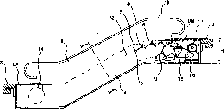
Fig. 4 is the lateral plan that shows the whole escalator of the step steering hardware with Fig. 2.
Fig. 5 is the enlarged side view that shows along the escalator of the line V-V planar interception of Fig. 4.
Fig. 6 is the planar view of another embodiment of connecting bridge that shows the link rod of Fig. 1.
The specific embodiment
Below, an embodiment of passenger conveyor of the present invention is described to escalator shown in Figure 5 with reference to Fig. 1.
As mentioned above Zhi Cheng front-wheel 6 and trailing wheel 7 respectively a pair of left and right sides front- wheel guide rail 10,10 in being installed on main frame 4 ' and a pair of left and right sides trailing wheel guide rail 11,11 ' (Fig. 5) go up and rotate and move.Rotation by front-wheel 6 and trailing wheel 7 and moving, step 5 can and move along the top machine chamber UM in the vertical two ends that are arranged on main frame 4 and path forward between the bottom machine chamber LM and return path circulation.
In order to make a plurality of step 5 circulations and to move, each step all links to each other with the step chain 12 of annular.The step chain is arranged in the both sides of Width of step 5 12, and each step chain is centered around on the step chain driven sprocket 14 of the step chain-driving sprocket wheel 13 of a supporting top machine chamber UM and a supporting bottom machine chamber LM.
As shown in Figure 3, step chain-driving sprocket wheel links to each other with rotating shaft 13S to 13, and left and right sides frame body 4A and the 4B supporting of rotating shaft 13S by constituting by main frame 4.One power transmission sprocket wheel 26 is coaxial to 13 with step chain-driving sprocket wheel, and is arranged in the side relative with step.The power of electrical motor 17 is transported to power transmission sprocket wheel 26 by a power transmission chain 15 and a reducing gear 16.
On the other hand, a pair of railing panel 18 that is made of railing is by left and right sides frame body 4A, 4B supporting, thereby is erected in the both sides by step chain 12 annular bonded assembly steps, and along the peripheral bootable handrail 19 of railing panel 18.Power and step 5 driven in synchronism of handrail 19 by being obtained by power transmission sprocket wheel 26.
The base portion of railing panel 18 is covered by an inner cap 20 and an enclosing cover 21, and in addition, the both sides of the Width of step 5 railings separate with a vertically disposed edge protection cover 22.In addition, the outer side covers of main frame 4 outer panels 23 that is made of trim board.
Most important structure is front-wheel 6, step chain 12 and bindiny mechanism in the said structure.In the present embodiment, front-wheel 6 is by wheel shaft 8 supportings along the outstanding step axle of the Width of step 5 as shown in Figure 1 to Figure 3, and is connected on the step chain 12 in a position in the outside of the front-wheel 6 of wheel shaft 8.
Below, with the connection structure of describing in detail between wheel shaft 8 and the step chain 12.That is to say, one end of link rod 24 is connected the axial end portion of the wheel shaft 8 of supporting front-wheel 6, thereby link rod can be around the axle rotation, and the other end of link rod 24 extends towards a side of trailing wheel 7, the other end of link rod 24 with link to each other by the corresponding step chain 12 in the extension end of link rod axle 25, thereby make link rod rotatable.Link rod axle 25 is parallel to wheel shaft 8 setting, and each link to each other with link rod 24 spools 8 and 25 be arranged to step chain 12 with right angle intersection.Step 5 and step chain 12 interconnect with this structure by the crank mechanism with wheel shaft 8, link rod 24 and link rod axle 25, that is to say, by a kind of have with axle and the link rod 24 that links to each other with axle that step chain 12 intersects at a right angle interconnect.Wherein, can in step 5, be provided with and be exclusively used in axle of bonded assembly and substitute wheel shaft 8 as the step axle.
A common chain link 12A and a special chain link 12B are connected on the step chain 12, and chain lever axis 25 links to each other with special chain link 25B, and the other end of link rod 24 links to each other with chain lever axis 25.Herein,
The shape of supposing regular link 12A and specific links 12B is equal, so that chain pitch equates mutually.Therefore, if chain pitch equates that mutually regular link 12A and specific links 12B needn't always be of similar shape.In addition, the other end of link rod 24 is connected with one that connecting rod pin 12P links to each other to substitute specific links 12B between the mutually adjacent regular link 12A.
In said structure, when step 5 during near step chain-driving sprocket wheel 13 (Fig. 2), be directed rotating and moving in the semisphere double track part (this part has the aperture widths m bigger slightly than the diameter of front-wheel 6) of front-wheel 6 by the guide rail in being arranged at knuckle section 10.Wherein, the purpose that is used to guide the semisphere guide rail 10 of front-wheel to be provided with is, the wheel shaft 8 of link rod 24 1 sides can be with respect to step chain 12 swing, thereby it is outstanding slightly that wheel shaft 8 is moved into towards the outside about the moving direction of the step chain 12 of the mobile route of the step chain 12 that moves along the neighboring of step chain-driving sprocket wheel 13.In addition, semisphere guide rail 10 forms, and is maximum center W at knuckle section terminal position place front-wheel 6 about the displacement at the center of the mobile route of step chain 12.Gap between the mutually adjacent step and can prevent interference (collision) between the mutual adjacent step 5 thus because the eccentric throw of the guide rail 10 that increases to center of maximum displacement W increases.
Wherein, when the length of the axle supporting spacing P of supporting link rod 24 than center of maximum displacement W in short-term, front-wheel 6 can move towards the outside of the moving direction of step chain 12 is outstanding with respect to the mobile route of step chain 12.In addition, when the length of the axle supporting spacing P of link rod 24 equaled center of maximum displacement W, link rod 24 partly was a level at center of maximum displacement W.Therefore, the displacing force of step chain 12 can not be transferred near the step 5 of the position of center of maximum displacement W part.Thus, because front-wheel 6 will be fallen the inside of semisphere guide rail 10 so that gap turn narrow is previous step 5 under the deadweight effect of step, perhaps because front-wheel 6 stops to move so that gap turn narrow is next step 5 there, the level and smooth steering operation of step 5 can be destroyed.Therefore, the length of the axle supporting spacing P of link rod 24 must be longer than center of maximum displacement W.
By doing the length of the axle supporting spacing P of link rod 24 longer than center of maximum displacement W, as mentioned above, move in the knuckle section smoothly at the front-wheel 6 that on the path outstanding, moves, thus, can avoid above-mentioned problem with respect to the mobile route outside of step chain.When front-wheel 6 arrive guide rail 10 in the return path sides ' horizontal component the time, link rod 24 will turn back to the initial condition parallel with step chain 12.
At that time, trailing wheel 7 is by having with the guide rail 11 ' guiding in the path of guide rail 10 ' different.
Following with reference to Fig. 2 describe in detail step 5 in the machine chamber of top from path forward to the mobile status of return path.As shown in Figure 2, be in a kind of like this state from the step 5 (a) of left-hand side on the guide rail 10,11 to right hand side shifting, the link rod 24 that promptly is connected on the wheel shaft 8 of front-wheel 6 is parallel with step chain 12, and the link rod axle 25 of the connecting bridge of link rod 24 and step chain 12 then is arranged in the rear positions of the moving direction of step 5.
When the step 5 (a) in being in this state arrived the neighboring of step chain-driving sprocket wheel 13 along with moving of chain 12, initial front-wheel 6 was by the hemisphere portion guiding along guide rail 10, and trailing wheel is directed by the hemisphere portion along guide rail 11 then.The neighboring that the aforesaid step that is directed 5 (b) begins by step chain-driving sprocket wheel 13 tilts, and leads downwards along the end of the step of moving direction.
Meanwhile, because the depth dimensions guide rail 10 by step 5 (b) is different with the radius of rotation and the center of turn of step chain-driving sprocket wheel 13 with center of turn with 11 radius of rotation, that is to say, because the mobile route of front-wheel 6 is towards with respect to the location, the outside of the moving direction of the mobile route of step chain 12, therefore, link rod 24 can be swung poor (the off centering size) of displacement different size.Because gapped between mutually adjacent step 5 (b)-5 (a) of turning point and 5 (b)-5 (c), therefore, the interference between the adjacent mutually step can be eliminated, and the steering operation of step is carried out smoothly.
The inclination of pedal also can be along with step 5 be shifted to 5 (c) and is increased from 5 (b), and when step surpassed the mid point of knuckle section, pedal tread was downward.When the degree of dip of step changed, shown in Fig. 6 (1), 6 (2), front-wheel 6 can move the neighboring of the chain-driving sprocket wheel 13 of topping bar and separate with it.Then, shown in Fig. 6 (3), 6 (4), front-wheel 6 moves and near the neighboring of step chain-driving sprocket wheel 13.When step 5 (b) returning add in the path by guide rail 10 ', during 11 ' guiding, the pedal complete face is downward, and link rod 24 becomes level and parallel with step chain 12.
As mentioned above, mobile route by making front-wheel 6 in the knuckle section is towards the displacement of the moving direction of step chain 12, interference between the mutual adjacent step in the knuckle section can be eliminated, and thus, even the stepped diameters of step chain-driving sprocket wheel 13 is done very for a short time, turning to also of step can be carried out smoothly.Therefore, the space that turns to of step 5 can minimize, and the height H of top machine chamber UM can be lowered.
Below the steering operation of the step among the machine chamber UM of top is described.In the machine chamber LM of bottom, along with step 5 contact progress paths, in return path prone pedal 5F change into towards on.Steering operation utilizes step chain driven sprocket 14 to carry out.Mechanism among mechanism and operation and the top machine chamber UM and class of operation are seemingly.That is to say, in the machine chamber LM of bottom, step 5 from return path to the steering operation in path forward be by a kind of with spend similar when putting upside down when Fig. 2 structure by scheme rotation 180.Therefore, omit description herein.
In order to realize that further the stable of step drive system moves, as required, can determine whether a special guide rail to be set in step chain 12, especially whether decision will be provided with a special guide rail that rotates and can correctly guide front-wheel 6 and link rod 24 with respect to chain 12.
The foregoing description is that example is carried out with escalator 1, the movable sidewalk that the present invention also can be applicable to parallel motion or tilts to move slightly.In this case, step can be called as the step pedal, and the step chain can be for being called the step step chain.
On the other hand, in having the escalator of said structure, in the process of mobile step 5, do along laterally limited moving (wriggling), thereby prevent step 5 contact with escalator machine such as edge protection cover 22 (Fig. 3) by the front-wheel 6 of front-wheel guide rail 10,10 ' guiding.
Yet, if front-wheel guide rail 10,10 ' setting accuracy lower, front-wheel 6 is wriggled along horizontal in the process that step 5 moves, thereby in the direction that can change the distance between step chain 12 and the step 5, produce a power, and, can in as the both ends of the link rod 24 of the connecting bridge between step 5 and the step chain 12, produce a moment load.If this moment load produces in the both ends of link rod 24 repeatedly, will rupture in both ends.
Therefore, in another embodiment of the present invention, as shown in Figure 6, bearing 30A, 30B are arranged between link rod 24 and the wheel shaft 8 and between link rod 24 and the link rod axle 25, like this, two bearings 30A, 30B can move vertically.That is to say, for the connection between step chain 12 and the link rod axle 25, bearing 30B one in wheel 32 be inserted in by the collar 31 and be arranged on the link rod axle 25 among the specific links 12B of step chain 12, and a foreign steamer 34 is inserted on the neighboring of interior wheel 32 of these a plurality of rollers 33, in addition, one housing 35 of link rod 24 is arranged in the periphery of foreign steamer 34, and foreign steamer 34 uses a ring 36 fixing with housing 35, and a bearing nut 37 is arranged in the link rod axle 25.
Similarly, for the connection between the link rod 24 of front-wheel 6, the interior wheel 42 of bearing 30A is inserted on the wheel shaft 8 by the collar 41, one foreign steamer 42 is inserted on the neighboring by the interior wheel 42 of a plurality of rollers 43, one housing 45 of link rod 24 is arranged in the neighboring of foreign steamer 44, housing 45 uses a ring 46 fixing with foreign steamer 44, and a bearing nut 47 is arranged on the top of wheel shaft 8.
As mentioned above, by means of connecting link rod 24 by cylindrical bearing between wheel shaft 8 and the step chain 12, wheel 32,42 slips and mobile in foreign steamer 34,44 can make by roller 33,43, and foreign steamer 34,44 can move, up to foreign steamer 34,44 with till the collar 41,51 or bearing nut 36,46 contact.
Therefore, even because front-wheel guide rail 10,10 ' setting accuracy low, front-wheel 6 is the along continuous straight runs wriggling in the process that moves of step, thereby the direction along the distance that can change step chain 12 and step 5 produces a power, the moment load that produces among bearing 30A, the 30B as the connecting bridge of link rod 24 can be suppressed on the reduced levels, and can suppress the shortening in the service life of connecting bridge.
In the above-described embodiments, two bearings that are arranged in the both ends of link rod 24 all are cylindrical bearings.Yet, even under such a case, that is, use ball bearing of main shaft to use cylindrical bearing as another bearing as a bearing, only there is a side can produce displacement thereby make, also the moment load that produces can be suppressed at reduced levels.
Claims (8)
1. passenger conveyor, this conveyer comprises: a plurality of steps that are equipped with front-wheel and trailing wheel, step moves and circulates, form pedal in path forward towards on and in return path, face down;
One step chain, this step chains round ground connects a plurality of steps;
And a step chain-driving sprocket wheel and a step chain driven sprocket, these sprocket wheels are by making the step chain and being centered around in the office, turning part between path and the return path forward on the sprocket wheel and the step chain is moved and circulate, wherein:
A wheel shaft that supports described front-wheel is outstanding towards Width from described step,
A link rod axle parallel with described wheel shaft is outstanding from the step chain that connects described step towards the direction of described step,
One end of link rod links to each other with described wheel shaft so that it is rotatable, and the other end of link rod extends towards the direction of described trailing wheel,
Extending on the side, the other end of described link rod links to each other with described link rod axle so that link rod rotates, and
One guiding device is installed in the knuckle section of described step, and described like this front-wheel moves in the outside of the rotation path of described step chain.
2. passenger conveyor, this conveyer comprises: a plurality of steps that are equipped with front-wheel and trailing wheel, step moves and circulates, form pedal in path forward towards on and in return path, face down;
One step chain, this step chains round ground connects a plurality of steps;
And a step chain-driving sprocket wheel and a step chain driven sprocket, these sprocket wheels are by making the step chain be centered around in the office, turning part between path and the return path forward the step chain is moved and circulating, wherein:
Described step links to each other with described step chain by a link rod, and described link rod links to each other with an axle that intersects at a right angle with described step chain, so that the swing in the described part of changing one's profession of described link rod, and
One is used for guiding the guide piece of described step to be installed in the knuckle section of described step, and the step side of described like this link rod can be swung in the outside of the rotation path of described step chain.
3. passenger conveyor as claimed in claim 2 is characterized in that, described guide piece is one to be used to guide the guide rail of described front-wheel.
4. passenger conveyor as claimed in claim 2 is characterized in that, described step chain is a pair of step chain that broad ways connects described step both sides, and described step chain is in the position that is arranged on step and described front-wheel and described trailing wheel opposite side.Guide piece is one to be used to guide the guide rail of described front-wheel.
5. passenger conveyor, this device comprises: a main frame that is installed between the ground that vertically separates mutually; A plurality of steps, these steps move and circulation make pedal in the path forward of described main frame towards on and in return path, face down; A pair of step chain, described step chain can connect described a plurality of step circlewise; Some front-wheels and some trailing wheels, described front-wheel and trailing wheel pass through each in the described a plurality of steps of axle supporting, move on described front-wheel and the described trailing wheel guide rail in being installed on described path forward and described return path; And step chain-driving sprocket wheel and step chain driven sprocket, these sprocket wheels are by making the step chain be centered around in the office, turning part between path and the return path forward the step chain is moved and circulating, wherein,
One crank mechanism setting also is connected between described step chain and the described step, and described crank mechanism makes in described knuckle section the mobile route of described front-wheel of the step that moves with respect to the outside displacement towards the moving direction of described step chain of the mobile route of described step chain.
6. passenger conveyor, this device comprises: a main frame that is installed between the ground that vertically separates mutually; A plurality of steps, these steps move and circulation make pedal in the path forward of described main frame towards on and in return path, face down; A pair of step chain, described step chain can connect described a plurality of step circlewise; Some front-wheels and some trailing wheels, described front-wheel and trailing wheel pass through each in the described a plurality of steps of axle supporting, move on described front-wheel and the described trailing wheel guide rail in being installed on described path forward and described return path; And step chain-driving sprocket wheel and step chain driven sprocket, these sprocket wheels are by making the step chain be centered around in the office, turning part between path and the return path forward the step chain is moved and circulating, wherein,
A wheel shaft that supports described front-wheel and described step chain interconnects by link rod, thereby makes described wheel shaft swing, and described link rod extends towards the direction of described trailing wheel;
The wheel shaft and the described step chain of the described front-wheel of one supporting interconnect by link rod, and are used for guide rail at the described front-wheel of described knuckle section guiding and are installed in the position with respect to the outside of the moving direction of the described step chain of the mobile route of described step chain.
7. passenger conveyor, this device comprises: a plurality of steps, these steps move and circulate, and it is downward to be formed on forward in the path pedal tread pedal tread upwards and in return path; One step chain, this step chains round ground connects a plurality of steps; And a step chain-driving sprocket wheel and a step chain driven sprocket, these sprocket wheels are by making the step chain be centered around in the office, turning part between path and the return path forward the step chain is moved and circulating, wherein:
One wheel shaft and the described step chain of supporting front-wheel interconnect by link rod, thereby make described wheel shaft swing, described link rod extends towards the direction of described trailing wheel, and a guide piece that is used for guiding described front-wheel is installed in described knuckle section in a position with respect to the moving direction outside of the described step chain of the mobile route of described step chain;
The wheel shaft and the described step chain that support the guide wheel of described step interconnect by a link rod, and the connecting bridge of described link rod can move vertically.
8. passenger conveyor as claimed in claim 7 is characterized in that the described connecting bridge of described link rod has the bearing of a displacement vertically.
Applications Claiming Priority (1)
| Application Number | Priority Date | Filing Date | Title |
|---|---|---|---|
| PCT/JP2000/004243 WO2002000542A1 (en) | 2000-06-28 | 2000-06-28 | Passenger conveyor |
Publications (2)
| Publication Number | Publication Date |
|---|---|
| CN1454179A CN1454179A (en) | 2003-11-05 |
| CN1248954C true CN1248954C (en) | 2006-04-05 |
Family
ID=11736193
Family Applications (1)
| Application Number | Title | Priority Date | Filing Date |
|---|---|---|---|
| CN00819691.5A Expired - Fee Related CN1248954C (en) | 2000-06-28 | 2000-06-28 | Passenger conveyor |
Country Status (6)
| Country | Link |
|---|---|
| EP (1) | EP1306342B1 (en) |
| JP (1) | JP3699957B2 (en) |
| CN (1) | CN1248954C (en) |
| DE (1) | DE60045563D1 (en) |
| MY (1) | MY128204A (en) |
| WO (1) | WO2002000542A1 (en) |
Families Citing this family (15)
| Publication number | Priority date | Publication date | Assignee | Title |
|---|---|---|---|---|
| JP4927367B2 (en) * | 2005-09-21 | 2012-05-09 | 東芝エレベータ株式会社 | Passenger conveyor step rollers |
| ES2573674T3 (en) * | 2006-12-21 | 2016-06-09 | Inventio Ag | Drive system for a sliding chain translation device |
| CN101456516B (en) * | 2007-12-13 | 2013-11-13 | 泰森克鲁普电梯(Es/Pbb)有限公司 | Conveying system for conveying passenger/goods |
| CN102442602A (en) * | 2010-10-08 | 2012-05-09 | 苏州帝奥电梯有限公司 | Main and auxiliary wheel for stair steps of automatic escalator |
| WO2014084805A2 (en) * | 2012-11-01 | 2014-06-05 | Otis Elevator Company | Offset pallet guidance for passenger conveyor |
| EP2914535A4 (en) * | 2012-11-01 | 2017-10-25 | Otis Elevator Company | Pallet return in moving walkways |
| NO335839B1 (en) | 2012-12-10 | 2015-03-02 | Jakob Hatteland Logistics As | Robot for transporting storage containers |
| GB201314313D0 (en) | 2013-08-09 | 2013-09-25 | Ocado Ltd | Apparatus for retrieving units from a storage system |
| US11858738B2 (en) | 2013-08-09 | 2024-01-02 | Ocado Innovation Limited | Apparatus for retrieving units from a storage system |
| NO337544B1 (en) | 2014-06-19 | 2016-05-02 | Jakob Hatteland Logistics As | Remote controlled vehicle assembly to pick up storage containers from a storage system |
| CN107531462B (en) * | 2015-04-16 | 2019-05-31 | 因温特奥股份公司 | Escalator with common reversion rail |
| CN107265274B (en) * | 2017-07-07 | 2019-03-08 | 江苏品尚机械科技有限公司 | A kind of moving sidewalk |
| EP3473576A1 (en) | 2017-10-20 | 2019-04-24 | Otis Elevator Company | Chain drive for a people conveyor |
| EP3569554B1 (en) * | 2018-05-16 | 2021-02-24 | Otis Elevator Company | Drive system for a people conveyor |
| CN109052131B (en) * | 2018-10-17 | 2023-09-08 | 苏州奔一机电有限公司 | Novel step spindle seat |
Family Cites Families (4)
| Publication number | Priority date | Publication date | Assignee | Title |
|---|---|---|---|---|
| JPS5211833B2 (en) * | 1972-09-29 | 1977-04-02 | ||
| JPS58207207A (en) * | 1982-05-28 | 1983-12-02 | Hitachi Ltd | Chain |
| JP2552745B2 (en) * | 1990-01-16 | 1996-11-13 | 三菱電機株式会社 | Curve escalator |
| JP3432745B2 (en) * | 1997-06-17 | 2003-08-04 | 日本フィレスタ株式会社 | Passenger conveyor equipment |
-
2000
- 2000-06-28 JP JP2002505298A patent/JP3699957B2/en not_active Expired - Fee Related
- 2000-06-28 CN CN00819691.5A patent/CN1248954C/en not_active Expired - Fee Related
- 2000-06-28 EP EP00942362A patent/EP1306342B1/en not_active Expired - Lifetime
- 2000-06-28 DE DE60045563T patent/DE60045563D1/en not_active Expired - Lifetime
- 2000-06-28 WO PCT/JP2000/004243 patent/WO2002000542A1/en active Application Filing
- 2000-10-18 MY MYPI20004880A patent/MY128204A/en unknown
Also Published As
| Publication number | Publication date |
|---|---|
| MY128204A (en) | 2007-01-31 |
| DE60045563D1 (en) | 2011-03-03 |
| EP1306342B1 (en) | 2011-01-19 |
| WO2002000542A1 (en) | 2002-01-03 |
| EP1306342A4 (en) | 2006-05-17 |
| JP3699957B2 (en) | 2005-09-28 |
| EP1306342A1 (en) | 2003-05-02 |
| CN1454179A (en) | 2003-11-05 |
Similar Documents
| Publication | Publication Date | Title |
|---|---|---|
| CN1248954C (en) | Passenger conveyor | |
| EP1791776B1 (en) | Method and apparatus for moving a pallet running on wheels in a travelator or equivalent | |
| KR940005950B1 (en) | Escalator | |
| CN102712425A (en) | Conveyor system for conveying objects, and immersion treatment system having such a conveyor system | |
| EP1680347B1 (en) | Turning device for conveyor | |
| CN1241817C (en) | Method for guiding plate link chainsin area of reversing devices of pedestrian conveyor system | |
| CN114275436A (en) | Shuttle car | |
| CN101048312A (en) | Automobile body moving and placing method, and moving and placing device | |
| CN1140788A (en) | Storage system | |
| CN1173877C (en) | Escalator | |
| CN1503762A (en) | Sloped part high-speed escalator | |
| CN1181346A (en) | Terminal rail for passenger conveyor | |
| RU2109673C1 (en) | Bow-shaped escalator drive system | |
| CN1167602C (en) | Passengers transporting device | |
| JP7045193B2 (en) | Lifting and transporting device | |
| CN214347954U (en) | Transmission device and sorting equipment | |
| CN1906114A (en) | Device for restraining the rise of a step roller of a people conveyor | |
| CN101080356A (en) | Escalator of type in which intermediate section thereof is accelerated | |
| CN1727610A (en) | Stereo parking appts. | |
| JP3147668B2 (en) | A multi-story parking lot where the treadboard is tilted by a turning drive | |
| CN100340732C (en) | Stereo parking appts. | |
| KR102451381B1 (en) | Laterally movement device of mobile robot | |
| JP7560115B2 (en) | Lift-type parking device | |
| CN1099517C (en) | Fascia drop-proof device of mechanical parking equipment | |
| CN1231649C (en) | Mechanical car stopping device |
Legal Events
| Date | Code | Title | Description |
|---|---|---|---|
| C06 | Publication | ||
| PB01 | Publication | ||
| C10 | Entry into substantive examination | ||
| SE01 | Entry into force of request for substantive examination | ||
| C14 | Grant of patent or utility model | ||
| GR01 | Patent grant | ||
| CF01 | Termination of patent right due to non-payment of annual fee |
Granted publication date: 20060405 Termination date: 20160628 |
|
| CF01 | Termination of patent right due to non-payment of annual fee |