CN1244450C - Machine plate replacing device - Google Patents
Machine plate replacing device Download PDFInfo
- Publication number
- CN1244450C CN1244450C CNB031548504A CN03154850A CN1244450C CN 1244450 C CN1244450 C CN 1244450C CN B031548504 A CNB031548504 A CN B031548504A CN 03154850 A CN03154850 A CN 03154850A CN 1244450 C CN1244450 C CN 1244450C
- Authority
- CN
- China
- Prior art keywords
- forme
- loader
- old
- plate cylinder
- discharge
- Prior art date
- Legal status (The legal status is an assumption and is not a legal conclusion. Google has not performed a legal analysis and makes no representation as to the accuracy of the status listed.)
- Expired - Fee Related
Links
Images


Classifications
-
- B—PERFORMING OPERATIONS; TRANSPORTING
- B41—PRINTING; LINING MACHINES; TYPEWRITERS; STAMPS
- B41F—PRINTING MACHINES OR PRESSES
- B41F27/00—Devices for attaching printing elements or formes to supports
- B41F27/12—Devices for attaching printing elements or formes to supports for attaching flexible printing formes
- B41F27/1206—Feeding to or removing from the forme cylinder
-
- B—PERFORMING OPERATIONS; TRANSPORTING
- B41—PRINTING; LINING MACHINES; TYPEWRITERS; STAMPS
- B41P—INDEXING SCHEME RELATING TO PRINTING, LINING MACHINES, TYPEWRITERS, AND TO STAMPS
- B41P2227/00—Mounting or handling printing plates; Forming printing surfaces in situ
- B41P2227/60—Devices for transferring printing plates
Abstract
A plate changing apparatus includes a loader, air cylinder, and removed plate recovery section. The loader is supported by a frame to be movable substantially parallel to a sheet convey direction, and feeds a new plate to a plate cylinder. The air cylinder moves the loader from a retreat position to a wait position close to the plate cylinder during plate changing. The removed plate recovery section is fixed to the frame and recovers an old plate discharged from the plate cylinder.
Description
Technical field
The present invention relates to a kind of device for changing of printing plates that is used for that new forme is provided to plate cylinder and reclaims old forme from plate cylinder.
Background technology
The device for changing of printing plates of this kind form is open in Japanese patent application publication No. No.2001-80041.In the device for changing of printing plates of this reference, be used for keeping the forme holding device of new forme to have being used to storing the old forme storage compartment of the old forme of discharging from plate cylinder.In traditional device for changing of printing plates, in the oscillating motion of forme holding device, when new forme moved to the forme supplying position that can be fed into plate cylinder, the old forme of discharging from plate cylinder was stored in old forme storage compartment.
In above-mentioned traditional device for changing of printing plates, when the old forme storage compartment that is used for storing the old forme of discharging from plate cylinder was arranged on the forme holding device, the forme holding device became big at the paper throughput direction.Owing to the restriction of installing space and because traction paper bobbin tension force becomes stable, the increase in gap is limited between printing equipment.Therefore, when forme becomes big or forme holding device when becoming big, make the operation of from the forme holding device that is arranged on the space between the printing equipment, extracting old forme become very loaded down with trivial details.
Because old forme storage compartment is formed in the forme holding device, except that old forme storage compartment, the drive unit that is used to store old forme also must be combined into the forme holding device, and therefore, it is heavy that forme holding device itself also becomes big change.As a result, the drive unit that is used to swing the forme holding device also becomes greatly, make reduce device size become impossible.
Summary of the invention
One of purpose of the present invention is to provide a kind of convenience to extract the device for changing of printing plates of old forme out from the forme holding device.
Another object of the present invention is to provide a kind of device for changing of printing plates that reduces size.
To achieve these goals, it provides the device for changing of printing plates of the printed panel on a kind of plate cylinder that is used for changing printing machine, wherein said printing machine is used for printing on the paper of carrying by printing machine, and described device for changing of printing plates comprises: by frame support to be parallel to the loader that the paper throughput direction moved and be used for new forme is fed into plate cylinder; The loader mobile device, it is used for moving described loader to move between holding fix, retracted position and forme supplying position, wherein at described holding fix, described loader is arranged to the plumbness near described plate cylinder, at described retracted position, described loader is arranged to leave the plumbness of described plate cylinder, and at described forme supplying position, described loader is arranged to heeling condition, in this heeling condition, the far-end of described loader is positioned adjacent to described plate cylinder, and wherein said loader is clamped described new forme; And be fixed to frame to reclaim from the forme discharger of the old forme of plate cylinder discharge.
Preferably, described loader comprises the guiding piece that is used for the old forme of discharging from plate cylinder is directed to described forme discharger.
Preferably, described loader comprises the withdrawing device that is used for extracting out from plate cylinder old forme.
Preferably, device for changing of printing plates also comprises: be used for supporting described loader swingably and be parallel to the base that the paper throughput direction moves between the forme supplying position of vertical holding fix and inclination; And drive unit, it is used for during changing of printing plates described loader being driven into the forme supplying position from holding fix, with the far-end that moves described loader so that described far-end near described plate cylinder, wherein said loader is clamped described new forme.
Preferably, described loader comprises: be used for when described loader is positioned at the forme supplying position, from plate cylinder, extract the withdrawing device of old forme out, and the old forme that is used for extracting out from plate cylinder by described withdrawing device is directed to the guiding piece of described forme discharger by described loader.
Preferably, described loader comprises when described loader is positioned at the forme supplying position, be used to change forme discharge path that is used for old forme and the conversion guiding piece that is used for the forme feeding path of new forme, and described conversion guiding piece will be directed to described forme discharger by the forme discharge path at the old forme that forme was discharged between expulsive stage from plate cylinder.
Preferably, described forme discharger is discharged the old forme of discharging from plate cylinder by described loader.
Preferably, described forme discharger comprises: hook-like part, it supports to can be forward and move backward with shift-in and be used for the forme discharge path of old forme and shift out from the forme discharge path that is used for old forme, described hook-like part is temporarily return from the forme discharge path by the sweep that row advances old forme one end of forme discharge path, and under its weight effect shift-in forme discharge path forward, and be used for hook-like part mobile device that described hook-like part is moved up.
Preferably, described forme discharger comprises: hook-like part, it supports to can be forward and move backward with shift-in and be used for the forme discharge path of old forme and shift out from the forme discharge path that is used for old forme, and can combine with the sweep of described old forme one end; Be used for setovering described hook-like part with the biasing member of shift-in forme discharge path forward in a direction; The bias force that is used to overcome described biasing member enters the stop of forme discharge path to stop described hook-like part to travel forward, and is used for discharging the hook-like part mobile device that direction moves described hook-like part at forme.
Preferably, described forme discharger comprises the discharge forme guided plate that vertically guides and discharge the old forme of discharging from plate cylinder along the front surface of printing equipment.
Description of drawings
Fig. 1 be show according to one embodiment of the present invention be used for perfecting press device for changing of printing plates sketch is set;
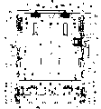
Fig. 2 is the front view that shows device for changing of printing plates among Fig. 1;
Fig. 3 shows the sketch that is provided with of going up device for changing of printing plates in the device for changing of printing plates shown in Figure 1;
Fig. 4 shows to be formed at the exploded front view that goes up the last loader of device for changing of printing plates shown in Figure 3;
Fig. 5 A is the sketch that is provided with that shows last loader shown in Figure 3, and Fig. 5 B and Fig. 5 C are the views that shows first, second adjusted part shape respectively;
Fig. 6 shows the zoomed-in view of going up the loader distal portions among Fig. 3;
Fig. 7 A is that the zoomed-in view that shows the part of V I of Fig. 3 is operated with the forme feeding that loader is described, and Fig. 7 B shows the view that is used to specify the second old forme drawing mechanism;
Fig. 8 is the zoomed-in view that shows the part of V III of Fig. 3;
Fig. 9 is the direction that shows the arrow IX from Fig. 3 view when watching;
Figure 10 A to 10E be the forme that is presented at device for changing of printing plates shown in Figure 1 discharge and the forme feeding during the view of loader state;
Figure 11 be show device for changing of printing plates shown in Figure 1 following device for changing of printing plates sketch is set;
Figure 12 is the part zoomed-in view that shows when arrow XII direction from Figure 11 is watched;
Figure 13 is the view that shows when arrow XIII direction from Figure 12 is watched;
Figure 14 is the sketch that is provided with that shows following loader shown in Figure 11;
Figure 15 is the exploded front view that shows following loader shown in Figure 11;
Figure 16 shows that the zoomed-in view of part XVI of Figure 14 is to illustrate down the forme discharging operation of device for changing of printing plates;
Figure 17 is that the zoomed-in view that shows the part XVI of Figure 14 is operated with the forme feeding that device for changing of printing plates is described down;
Figure 18 is the zoomed-in view that shows the part XVIII of Figure 14;
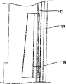
Figure 19 shows the forme discharge path of device for changing of printing plates and the view in forme feeding path gone up shown in Figure 1;
Figure 20 shows the forme discharge path of device for changing of printing plates down shown in Figure 1 and the view in forme feeding path; And
Figure 21 A and 21B are the views that shows the other method of the bar that separates new forme shown in Figure 8 and sweep.
The specific embodiment
Hereinafter, describe with reference to Fig. 1 to 18 pair of device for changing of printing plates according to embodiment of the present invention.In this embodiment in detail, the embodiment that device for changing of printing plates wherein is applied to perfecting press will be described.
See figures.1.and.2, in being used on printing on the printed matter front printing 5A and the following printing 5B that is used for printing on the printed matter back side being arranged on a pair of relative frame 3,4 of printing equipment 1.Last printing 5A has the last plate cylinder 6A that forme is fixed on outer surface, and the last blanket cylinder 7A that is used to contact relative last plate cylinder 6A.Following printing 5B has the following plate cylinder 6B that forme is fixed on outer surface, and the following blanket cylinder 7B that is used to contact relative following plate cylinder 6B.Blanket cylinder 7A, 7B are set to contact toward each other, and printing target object such as roll web are by between it.
When printing ink and damping water when ink feeder (not shown) and humidity control device (not shown) supply to plate cylinder 6A and 6B respectively, be delivered to blanket cylinder 7A and 7B respectively corresponding to the printing ink part that is fixed on the printed patterns on plate cylinder 6A and the 6B.When the printing target object passed between blanket cylinder 7A and the 7B, printed patterns just was printed on its two sides.
<last device for changing of printing plates 〉
Last device for changing of printing plates 17 is by being fixed to go up discharging forme recovery section 30 and will being directed to discharge forme recovery section 30 from the old forme that last plate cylinder 6A discharges and the last loader 20 that new forme is fed into plate cylinder 6A is constituted of frame 3,4.
As shown in Figure 1, last loader 20 supports by paired outer frame 22,23 (Fig. 2), so that it can be basically perpendicular to swing between the holding fix (position of being represented by solid line) of paper bobbin throughput direction (direction of arrow A-B) and the forme supplying position (position that the chain-dotted line that is replaced by length is represented) at it in Fig. 1 in Fig. 1, at the forme supplying position, itself and holding fix tilt to move its lower end near last plate cylinder 6A outer surface, so that the new forme in last loader 20 can be fed into plate cylinder 6A. Outer frame 22,23 on a pair of base 24 respect to one another vertically upward.
A pair of upwardly extending guide rail 25 is respectively fixed to frame 3,4 along arrow A-B side, and base 24 is supported on the guide rail 25 so that move along arrow A-B direction.Base 24 is by being fixed to frame 4 and moving in arrow A-B direction at first air cylinder 26 of the upwardly extending no bar in arrow A-B side.
When base 24 moved, last loader 20 can move from the hard translation of retracted position that the holding fix of being represented by solid line Fig. 1 is represented to the chain-dotted line that is replaced by unexpected misfortune in the working space 21 between the printing equipment 2 that is arranged on printing equipment 1 and closes on.By the support member horizontal fixed to the step 27 of left and right frame 3,4 be arranged on working space 21 below.
<on discharge the forme recovery section
As shown in Figure 3, discharge the plane that forme recovery section 30 has between frame of being fixed on 3,4 on and discharge forme guided plate 40.Discharge forme guided plate 40 by having a down dip part 41 and form with the continuous upwards upstanding portion 42 of its sloping portion 41.Sloping portion 41 to be going up the inclined at inclination angles of loader 20 no better than when last loader 20 is positioned at the forme supplying position, and its outer surface of relative last plate cylinder 6A of end in contact down.Upstanding portion 42 is vertical along the front surface of printing equipment 1 substantially.
Extend between the frame 3,4 and when from the time have a U-shaped guide rod 43 be fixed to sloping portion 41.Guide rod 43 has a large amount of rotation guide reels 44 at the gap location with sloping portion 41 surfaces.A pair of removal prevents that part 45 (only having shown) is fixed to outer frame 22,23 so that relative two ends of horizontal direction of the upstanding portion 42 of forme guided plate 40 are discharged on the edge.
In this is provided with, the old forme 10 of discharging from last plate cylinder 6A guides to move up between the upstanding portion 42 of guide reel 44 and discharge forme guided plate 40, prevent part 45 guiding by upstanding portion 42 and removal then, to reclaim by last discharge forme recovery section 30.The direction of old printing forme 10 arrow B in Fig. 3 that reclaims by last discharge forme recovery section 30 is discharged.
<the first old forme drawing mechanism 〉
As shown in Figure 8, the upstanding portion 42 of discharge forme guided plate 40 has the first old forme drawing mechanism 50.The first old forme drawing mechanism 50 is mainly by second air cylinder 51 (Fig. 9) as a pair of no bar of drive source, and is used for hook-like part 52 formations with the sweep effect of the back 10b of the old forme 10 of discharging from last plate cylinder 6A.
As shown in Figure 9.Air cylinder 51 vertically extends and is respectively fixed to frame 3,4 (only showing), and moving member 53 vertically moves thereon.The connector 54 that extends between frame 3,4 moves by guiding bearing pin 56 vertical support that are respectively fixed to air cylinder 51 by carriage 55.When moving member 53 moves, connector 54 by with move from moving member 53 upwardly extending connectors 57 are therewith vertical.
In this was provided with, when the old forme 10 that will discharge was directed to upstanding portion 42 and discharge and prevents between the part 45, the sweep of back 10b leaned against on the hook-like part 52.At this moment, hook-like part 52 overcome its gravity make into the center the axle 59 the rotation so that temporarily prevent to withdraw between the part 45 from upstanding portion 42 and removal.When old forme 10 further moved up, the sweep of hook-like part 52 and back 10b was separated from one another, and hook-like part 52 is moving forward to upstanding portion 42 under the weight effect and removal prevents between the part 45 again.
In this state, when the moving member 53 of air cylinder 51 moved up, hook-like part 52 moved up.When hook-like part 52 moved up, the lower surface effect of the sweep of the back 10b of itself and old forme 10 was upwards to spur old forme 10.According to this embodiment, hook-like part 52 moves forward to upstanding portion 42 under its weight effect and removal prevents between the part 45.Therefore, do not need to be used for the drive source of mobile hook-like part 52, so that designs simplification and reduce size.
<last loader 〉
As shown in Figure 4, last loader 20 has a pair of at the gap location interior framework 71,72 respect to one another greater than new forme 11 width.Shown in Fig. 5 A, interior framework 72 has along the elongated hole 73 of its slit-shaped that vertically forms, so that new forme 11 can insert from the side of last loader 20.As shown in Figure 4, flat first regulating part 74 is fixed in the interior framework 71 so that parallel with interior framework 71.One side of the new forme 11 that inserts from elongated hole 73 leans against on first regulating part 74.
Tabular second regulating part 75 of relative first regulating part 74 is arranged in the interior framework 72.Shown in Fig. 5 B and 5C, second regulating part 75 by elongated hole 73 less than first regulating part 74, so that it will be not the insert action of the new forme 11 that inserts from elongated hole 73 is regulated.More particularly, first regulating part 74 has the shape of overlap joint elongated hole 73, and when inserting forme with box lunch, a side of new forme 11 leans against on first regulating part 74.Second regulating part 75 has the little and corresponding size of width dimensions elongated hole 73 of size than first regulating part 74, and when inserting forme with box lunch, a side of new forme 11 does not lean against on second regulating part 75.
Second regulating part 75 supports so that move with the direction of separating with first regulating part 74 close by interior framework 72.Second regulating part 75 is shifted to first regulating part 74 (direction of arrow C Fig. 4) by the 3rd air cylinder 77 (Fig. 4) that is fixed to interior framework 72 a little from initial position.Each all is divided into upper and lower regulating part first, second regulating part 74,75, has only shown a part in Fig. 4.
In this is provided with, the new forme 11 that inserts from elongated hole 73 leans against on the one side of first regulating part 74, and moving by swing mechanism (will be explained below), and be contained in loosely in the forme holding portion 78 that is formed between two regulating parts 74 and 75 perpendicular to direction towards the surface direction of new forme 11.Then, air cylinder 77 is shifted to first regulating part 74 with second regulating part 75, so that two regulating parts 74,75 are along laterally new forme 1 being positioned.
In addition, new forme 11 can be by the inner surface of second regulating part 75 that is tapered, and promptly another side of new forme 11 is close to surface on it on second regulating part 75, to position along horizontal direction.In the case, do not need to move second regulating part 75.If new forme 11 can be contained in by the operation of unique swing mechanism between two regulating parts 74,75, then the gap between two regulating parts 74,75 can be set at and equal new forme 11 in horizontal length.In the case, do not need to move second regulating part 75, or the inner surface of second regulating part 75 that do not need to be tapered.
<last swing mechanism 〉
As shown in Figure 4, axle 81 horizontal-extending between the upper end of interior framework 71,72.A pair of thin, elongated rectangle support forme 82 has the upper end by axle 81 pivotal support, and extends to the lower end near last loader 20 lower ends.Shown in Fig. 5 A, support forme 82 and have a plurality of oscillating rollers 83 that contact with the new forme 11 that inserts from elongated hole 73 and support by bar 108.
As shown in Figure 4, a pair of the 4th air cylinder 85 is fixed in the interior framework 71,72.Shown in Fig. 5 A, an end of each control stick 86 all pivotally is fixed on the cylinder rod end of corresponding the 4th air cylinder 85.The other end of each control stick 86 all is fixed on the axle 87 that supports rotation between the interior framework 71,72.Therefore, axle 87 produces clockwise and counterclockwise pivot rotation according to the seesawing of bar of the 4th air cylinder 85.
The near-end of a pair of control stick 88 is fixed to axle 87, and elongated hole 89 is formed in the pivot section of control stick 88.The axle that extends between interior framework 71,72 90 supports rotation by bearing between elongated hole 89.Each a end of a plurality of control stick 91 all is fixed to axle 90, and the other end of each control stick 91 supports a corresponding pressure roller 92 rotationally.The lower end of supporting forme 82 is fixed to axle 90 by forme 93.
In this is provided with, when the bar of the 4th air cylinder 85 is mobile backward, in the 87 counterclockwise pivot rotations of Fig. 6 axis, so the axle 87 that control stick 88 makes to the center rotates with axle 87 counterclockwise pivots.When control stick 88 pivots rotate, in Fig. 5 A, support forme 82 clockwise pivot rotations, so oscillating roller 83 also moves in the direction of arrow E.Therefore, new forme 11 supports by the roller 83 as swing mechanism (part), and is contained between aforesaid two regulating parts 74,75.
When the lower end of supporting forme 82 when the direction of arrow E moves, control stick 91 also moves by the direction of axle 90 in arrow E.Therefore, pressure roller 92 compresses the front 11a of new forme 11 in the direction of arrow E, locatees new forme 11 with the forme clamping jaw device 8A that goes up plate cylinder 6A relatively.
<new forme supporting mechanism 〉
As shown in Figure 4, the 5th air cylinder 100 of a pair of no bar is fixed in the interior framework 71,72.The 5th air cylinder 100 drives moving member 101 and vertically moves.The two ends of the carriage release lever 102 that extends between interior framework 71,72 are connected to moving member 101 by connector 101a.When moving member 101 moved, carriage release lever 102 integral body when it guides by a pair of guide rod 103 moved up.
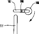
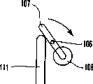
As shown in Figure 8, a pair of base 105 is fixed to carriage release lever 102 so that separated from one another by predeterminable range, is fixed to base 105 and have reversing L type pressing section 105a partly.As shown in Figure 4, support member 107 supports rotation by horizontally extending axle 106 on base 105 respectively, and level, the continuous a pair of bar 108 that extends are fixed to support member 107 between interior framework 71,72.
As shown in Figure 8, the stop bearing pin 109 with support member 107 effects extends upward from base 105 respectively.The downward pivot motion of the stop bearing pin 109 effect self-supporting part 107 by regulating its weight so that support member 107 remains on level substantially, that is, remains on and has the state that enters in the forme holding portion 78 that moves forward.As shown in Figure 4, the locking member 111 of rectangular ring vertically extends on horizontally extending horizon bar 112 between the interior framework 71,72, with corresponding with support member 107.
In this was provided with, when the moving member 101 of air cylinder 100 moves down, and support member 107 was when also moving down, and the front 11a of the new forme 11 that supports by bar 108 leans against on plate cylinder 6A and the forme maintenance roller 135.Then, as shown in Figure 8, when support member 107 leans against the upper end of locking member 111 and when further moving down, overcome the axle 106 counterclockwise pivots that its weight makes to the center and rotate.
Therefore, bar 108 is return from forme holding portion 78, and correspondingly, the sweep of the back 11b of bar 108 and new forme 11 is separated from one another.Then, pressing section 105a compresses the back 11b of new forme 11, so that front 11a can inject plate cylinder 6A.Under this mode,, do not need to be used for the driving mechanism of pivot swingle 108 when bar 108 and new forme 11 when being separated from one another.Therefore, structure obtains simplifying.
As shown in Figure 4, guide rod 120 levels are connected to the upper end near the outer frame 23 of the interior framework 72 with elongated hole 73.Guide rod 120 is arranged on a little the position higher than bar 108.Therefore, when new forme 11 is to inject when going up loader 20 from elongated hole 73, this will be explained below, and the sweep of the back 11b of new forme 11 temporarily is placed on the guide rod 120, so that the sweep of back 11b is by bar 108 level and smooth and channeling conduct and supports reliably.
<forme discharge/feeding conversion guided plate 〉
As shown in Figure 4, the 6th air cylinder 130 is fixed in the interior framework 71,72.As shown in Figure 6, an end of each control stick 131 all pivot be fixed on the rod end of respective air cylinder 130.Control stick 131 passes through from interior framework 71,72 upwardly extending axle 132 pivotal support.Forme discharge/feeding conversion guided plate 133 is connected to the other end of a control stick 131 and the other end of another control stick 131.
In this is provided with, when the bar of air cylinder 130 is mobile backward, forme discharge/feeding conversion guided plate 133 is represented as the solid line among Fig. 6, so that new forme 11 can inject among the plate cylinder 6A in the direction pivot rotation that makes to the arrow E of the axle 132 of pivot center.When the bar of air cylinder 130 moved forward, forme discharge/feeding conversion guided plate 133 was in the direction pivot rotation as the arrow F of the axle 132 of pivot center, so that can discharge old forme 10 from last plate cylinder 6A.
Forme keep roller 135 by the air cylinder (not shown) move with near and away from the outer surface of last plate cylinder 6A.In the forme feeding, when forme keeps the outer surface of the relative last plate cylinder 6A of roller 135 contacts, it injects the forme clamping jaw device 8A that goes up plate cylinder 6A with sweep of new forme 11 front 11a and back 11b, and new forme 11 compressed with the outer surface with last plate cylinder 6A forms tight the contact.
<the second old forme drawing mechanism 〉
As shown in Figure 4, the 7th air cylinder 140 is fixed on outside the interior framework 71,72.Shown in Fig. 7 B, an end of each control stick 141 all pivot is fixed on the rod end of respective air cylinder 140.And an end of corresponding control stick 142 all pivot be fixed on the other end of control stick 141.The other end of control stick 142 is axially fixed on the corresponding axle 143 of pivotal support by interior framework 71,72.The near-end of extracting control stick 144 at the second old forme that extends between the interior framework 71,72 out is axially fixed on the axle 143.
In this was provided with, when the bar of air cylinder 140 moved forward, in Fig. 7 B, axle 143 was by control stick 141 and 142 counterclockwise pivot rotations.When axle 143 pivots rotated, the swinging end 144a that the second old forme is extracted control stick 144 out moved to the position that the chain-dotted line that replaced by length is represented in the direction of arrow F from the position of being represented by solid line.Therefore, the second old forme is extracted the swinging end 144a of control stick 144 and the front 10a effect of old forme 10 out, and the sweep of the front 10a of old forme 10 is extracted out from the forme clamping jaw device 8A of last plate cylinder 6A by force.
As shown in Figure 4, the 8th air cylinder 150 with pivotal support cylinder end is fixed in the interior framework 71,72.Shown in Fig. 7 A, an end of each control stick 151 all pivotally is fixed on the rod end of respective air cylinder 150.Control stick 151 by interior framework 71,72 axial support so that make axle 152 pivots rotation respectively into pivot center.As shown in Figure 4, at the guide rod 153 that extends between the interior framework 71,72 horizontal-extending between the other end of the other end of a control stick 151 and another control stick 151.A plurality of rotating shaft rollers 155 support rotation by guide rod 153.
In this was provided with, when the bar of air cylinder 150 moved forward, control stick 151 made the axle 152 clockwise pivot rotations into pivot center.When control stick 151 pivots rotated, rotating shaft roller 155 direction that arrow E is represented in Fig. 7 A moved to the position of alternately being represented by the chain-dotted line of unexpected misfortune from the position of being represented by solid line.When rotating shaft roller 155 moves, it will press to plate cylinder 6A from the old forme 10 that last plate cylinder 6A discharges.Therefore, can utilize rotating shaft roller 155 to pass through the above-mentioned second old forme extraction control stick 144 reliably with old forme 10 extractions as rotating shaft.
Shown in Fig. 5 A, three discharge forme guided plates 161,162 and 163 are fixed to the lower end of loader 20 between the interior framework 71,72 continuously.It is corresponding with forme discharge/feeding conversion guided plate 133 to discharge forme guided plate 161, and discharge forme guided plate 162,163 is corresponding with the sloping portion 41 of the discharge forme guided plate 40 that is fixed to framework 3,4.In this was provided with, the old forme 10 of discharging from last plate cylinder 6A passed between discharge forme guided plate 161 and the forme discharge/feeding conversion guided plate 133, and is directed between the sloping portion 41 of discharging forme guided plate 162,163 and discharge forme guided plate 40.
<upward the oscillating motion of loader 〉
As shown in Figure 3, outer frame 22,23 swinging in the cross rest of last loader 20 by passing back shaft 170.As shown in Figure 4, a pair of cylinder end with the 9th air cylinder 171 of bar 172 is supported on pivot rotation in the outer frame 22,23.The rod end of bar 172 pivot respectively is fixed on the interior framework 71,72.
In this was provided with, as shown in Figure 3, when the bar 172 of air cylinder 171 moved forward, last loader 20 tilted, and its lower end is positioned at the forme supplying position near last plate cylinder 6A outer surface.When the bar 172 of air cylinder 171 was mobile backward, last loader 20 became vertical state and is positioned at holding fix.
<upward changing of printing plates the operation of plate cylinder 〉
At first, shown in Figure 10 A, last loader 20 moves to holding fix from retracted position.More particularly, when air cylinder 26 (Fig. 2) started, the retracted position that last loader 20 is represented at the direction chain-dotted line that unexpected misfortune replaces from by Fig. 1 of arrow A moved to the holding fix represented by solid line with near printing equipment 1.
Be positioned at holding fix in the loader 20, the sweep of new forme 11 back 11b is caught by guide rod 120, new forme 11 moves so that its elongated hole 73 from interior framework 72 injects loader 20 in the direction of arrow C.Then, the sweep of new forme 11 back 11b moves to bar 108 (Fig. 4) from guide rod 120, so that new forme 11 supports by himself weight vertical hanging and by bar 108.
Then, the bar 172 of air cylinder 171 moves forward, and correspondingly, last loader 20 tilts, and is positioned at the forme supplying position that the chain-dotted line that replaced by length among Fig. 1 is represented.In this state, upper and lower blanket cylinder 7A, 7B are separated from one another, and the clutch (not shown) between the driving mechanism of the driving mechanism of printing equipment 2 and Foldable device (not shown) separates.Then, shown in Figure 10 B, the drive mechanism of printing machine is so that upper and lower plate cylinder 6A, 6B forwards change (clockwise direction among Figure 10 B) to rotation about.
At this moment, be positioned at the lax corresponding substantially amount of circumferential length with last plate cylinder 6A of roll web 15 between printing equipment 1 and the Foldable device.The air cylinder (not shown) drives to move down dance roller 16, relaxes thereby eliminate.Then, the bar of air cylinder 130 (Fig. 7 A) moves forward, so that forme discharge/feeding conversion guided plate 133 moves to be positioned at the forme drain position in the direction of arrow F.Then, forme keeps roller 135 to begin to contact relative last plate cylinder 6A outer surface.
Then, the spool bars pivot of forme clamping jaw device 8A rotation, and the back 10b of old forme 10 separates with last plate cylinder 6A and emerges from the outer surface of last plate cylinder 6A.Then, when last plate cylinder 6A (counter clockwise direction in Fig. 7 A) rotation in the opposite direction, the back 10b of old forme 10 passes and discharges between forme guided plate 161 and the forme discharge/feeding conversion guided plate 133, and is directed between the sloping portion 41 of discharging forme guided plate 162,163 and discharge forme guided plate 40.Figure 19 has shown the forme discharge path X at this state.
Under this mode, change the far-end that guided plate 133 is set to the last loader 20 of the outer surface that contacts relative last plate cylinder 6A owing to be used to guide the discharge forme guided plate 161 of the old forme 10 of discharging from last plate cylinder 6A with forme discharges/feeding, so, can old forme 10 be directed to reliably by last loader 20 and discharge plate recovery section 30.Then, last plate cylinder 6A is (in Fig. 7 A counterclockwise) rotation in the opposite direction, correspondingly, as shown in Figure 8, the back 10b of old forme 10 is directed to the upstanding portion 42 and the discharge of discharging forme guided plate 40 prevents between the part 45.
At this moment, the sweep of old forme 10 leans against on the hook-like part 52, and hook-like part 52 temporarily prevents to return between the part 45 from the upstanding portion 42 and the discharge of discharging forme guided plate 40.Then, remove when this adjacency state, when the sweep of back 10b passed, hook-like part 52 moved forward from the forme discharge path by its weight once more.After hook-like part 52 restores, follow the forme discharging operation (old forme 10 moves up) of plate cylinder 6A pivot motion to stop substantially simultaneously, and the lower surface of back 10b sweep and hook-like part 52 effects.
Simultaneously, shown in Fig. 7 A, forme keeps roller 135 to separate with last plate cylinder 6A, and the bar of air cylinder 150 moves forward, so as rotating shaft roller 155 the direction of arrow E move with will from the back 10b of the plate cylinder 6A old forme 10 of discharging press to plate cylinder 6A.
Then, the bar of air cylinder 140 moves forward, and moves in the direction of arrow F so that the second old forme is extracted control stick 144 out, so that extract the front 10a of old forme 10 out from the forme clamping jaw device 8A of last plate cylinder 6A.Then, the moving member 53 of air cylinder 51 (Fig. 9) moves up, correspondingly, and the old forme 10 of hook-like part 52 pull-ups.
In this mode, the front 10a of the old forme 10 that compresses by rotating shaft roller 155 extracts control stick 144 out by the second old forme and extracts out from the forme clamping jaw device 8A of last plate cylinder 6A, and after this, the back 10b of old forme 10 is by hook-like part 52 pull-ups.Therefore, can reliably old forme 10 be discharged from last plate cylinder 6A.The old forme 10 of discharging reclaims and remains on going up of frame 3,4 sides and discharges in the forme recovery section 30.When next forme feeding EO, be recovered in the old forme 10 of discharging in the forme recovery section 30 by operating personnel from wherein discharging, this will be explained below.
<forme feeding operation 〉
As shown in Figure 6, when the air cylinder (not shown) drove, forme kept the outer surface of the relative last plate cylinder 6A of roller 135 contacts.Then, the bar of air cylinder 130 moves backward, so that forme discharge/feeding conversion guided plate 133 moves in the direction of arrow E, and is positioned at the forme supplying position.Then, the bar of air cylinder 85 moves backward, and in order to produce incentive action between two regulating parts 74,75, the new forme 11 that inserts from elongated hole 73 hangs down from bar 108, and leans against on first regulating part 74 at the one side.
Shown in Fig. 5 A, when the bar of the 4th air cylinder 85 was mobile backward, support forme 82 made the axle 81 clockwise pivots rotations into pivot center.Then, oscillating roller 83 also in Fig. 5 A the direction of arrow E move, and the new forme 11 that contacts with oscillating roller 83 is contained between two regulating parts 74,75.Simultaneously, when the lower end of supporting forme 82 when the direction of arrow E moves, control stick 91 moves in the direction of arrow E by axle 90.Therefore, pressure roller 92 compresses the front 11a of new forme 11 in the direction of arrow E, so that its location is with the forme clamping jaw device 8A of plate cylinder 6A on the correspondence.
Simultaneously, drive air cylinder 77 (Fig. 4) so that second regulating part 75 is shifted to first regulating part 74, with two regulating parts 74,75 at the new forme 11 of located lateral.Under this mode, different with previous technology, owing to be used on injecting that the mechanism of the new forme 11 in location is arranged on loader 20 before the plate cylinder 6A, and do not need to be provided for new forme 11 is directed to device between loader 20 and the last plate cylinder 6A.As a result, not only can reduce the size of equipment, and can adapt to the increase of plate size.
The moving member 101 of air cylinder 100 (Fig. 8) moves down, and correspondingly, support member 107 moves down.Then, the front 11a of the new forme 11 that supports by bar 108 leans against on plate cylinder 6A and the forme maintenance roller 135, so that stop moving downward of new forme 11.After this, support member 107 leans against the upper end of locking member 111.When support member 107 further moved down, it made the axle 106 counterclockwise pivot rotations into the center, and bar 108 is return from forme holding portion 78.Then, back 11b compresses by pressing section 105a, so that front 11a can inject among the forme clamping jaw device 8A of plate cylinder 6A.
In this state, when the last plate cylinder 6A direction of advance that arrow is represented in by Fig. 6 is rotated, lean against plate cylinder 6A and forme and keep the front 11a of the new forme 11 on the roller 135 to keep roller 135 to inject among the forme clamping jaw device 8A by forme.Last plate cylinder 6A approximately revolves and goes around, and correspondingly, the back 11b of new forme 11 injects among the forme clamping jaw device 8A.When the spool bars of forme clamping jaw device 8A was followed the pivot rotation, new forme 11 was fixed on the outer surface of plate cylinder 6A.Figure 19 has shown the forme feeding path Y of this kind situation.
When the fixing end of new forme 11, the bar 172 of air cylinder 171 (Fig. 3) moves backward, is set in vertical state and is positioned at holding fix so that go up loader 20.Then, as among Fig. 1 by shown in the unexpected misfortune chain-dotted line, air cylinder 26 (Fig. 2) drives so that go up loader 20 and separate and make it be positioned at holding fix from printing equipment 1.Figure 10 E has shown this state.After this, shown in Figure 11 E, the clutch between the driving mechanism of the driving mechanism of printing equipment 2 and Foldable device (not shown) connects, to drive the driver of printing machine.Then, dance roller 16 moves up, and the operator pulls out the old forme 10 that is recovered in the discharge forme recovery section 30 in the direction of arrow B, to extract it out to working space 21.
Under this mode, since old forme 10 reclaim (extract out, receive and keep) be set to frame 3,4 on discharge in the forme recovery section 30, and do not need to be arranged on the device that is used to reclaim old forme 10 in the loader 20, can reduce size in paper throughput direction (direction of arrow A-B) and go up loader 20.Because last loader 20 moves to retracted position, the working space of going up discharge forme recovery section 30 that then is fixed to frame 3,4 becomes big, and therefore, old forme 10 can be discharged from last loader 20 easily.
Since last loader 20 itself can be reduced in size and be made as light-duty, so, can reduce the size of the air cylinder 171,26 that is used to swing and move loader 20, so that the minimizing device size.
<following device for changing of printing plates 〉
As shown in Figure 1, following device for changing of printing plates 217 is by the following discharge forme recovery section 230 that is fixed to frame 3,4 and be used for being directed to down from the old forme that following plate cylinder 6B discharges discharge forme recovery section 230 and the following loader 220 that new forme is fed into down plate cylinder 6B is constituted.
Following loader 220 supports by a pair of outer frame 222,223, so that it can be swung between holding fix that is basically perpendicular to roll web throughput direction (direction of arrow A-B) (position that solid line is represented among Fig. 1) and forme supplying position (position that the chain-dotted line that length replaces in by Fig. 1 is represented), at the forme supplying position, itself and holding fix tilt, and the close outer surface of plate cylinder 6B down in its upper end.At the forme supplying position, the new forme in following loader 220 can be fed into plate cylinder 6B down.
As shown in Figure 2, outer frame 222,223 toward each other, stand vertically on a pair of base 224.In arrow A-B direction (Fig. 1), promptly the guide rail 225 that extends in the direction of printing equipment 1 and printing equipment 2 centerings is respectively fixed to frame 3,4, and base 224 is supported on the guide rail 225 so that move in arrow A-B direction.Base 224 moves in arrow A-B direction by no bar the tenth air cylinder 226 that is fixed to frame 3.
When base 224 moved, following loader 220 moved between holding fix that the chain-dotted line that is replaced by solid line and unexpected misfortune in respectively by Fig. 1 is represented and the retracted position by being formed at the working space between the printing equipment 1,2.Below working space 221, step 227 passes through support member (not shown) horizontal fixed to frame 3,4.
<following discharge forme recovery section 〉
As shown in figure 11, following discharge forme recovery section 230 has the tabular discharge forme guided plate 231 that frame of being fixed to 3,4 also substantially vertically is arranged at the front of printing equipment.Discharge the upper part bending of forme guided plate 231, so that the close outer surface of plate cylinder 6B down in its upper end.A pair of discharge prevents that part 232 (only showing) is fixed to outer frame 222,223 so that relative with two ends in the horizontal direction of discharging forme guided plate 231.
In this was provided with, the old forme 10 of discharging from following plate cylinder 6B prevented guiding downwards between the part 232 at discharge forme guided plate 231 and discharge.Being recovered in the old forme 10 of discharging in the forme recovery section 210 discharges along the direction of being represented by arrow B among Figure 11.
<the first old forme drawing mechanism 〉
As shown in figure 12, the first old forme drawing mechanism 240 is arranged on discharge forme guided plate 231 and discharge prevents below the part 232, so that extract the front 10a of old forme 10 out from the clamping jaw device 8B of following plate cylinder 6B in forme is discharged.
As shown in figure 13, bedplate 242 is fixed on two minor axises 241 that protrude from frame 4, and the cylinder end pivoting of the 11 air cylinder 243 be fixed to base version 242.As shown in figure 12, the bar 244 of air cylinder 243 pivotally is fixed on the crooked swing component 245.The near-end of swing component 245 supports by base version 242 so that make axle 246 swings into the center.Hook-like part 247 rotatably is supported on the swinging end of swing component 245 by axle 248.
Hook-like part 247 is by being wound on torsion-coil spring 249 (Figure 13) biasing of axle on 248 so that pivot rotation counterclockwise in Figure 12, and its pivot moves through the latch 250 that protrudes from base version 242 and regulates.In this is provided with, in the mobile backward original state of the bar 244 of air cylinder 243, in Figure 12, hook-like part 247 by with the effect of latch 250, overcome the clockwise pivot rotation of effect of torsion-coil spring 249, and return from the discharge forme guided plate of representing by solid line Figure 12 231.When the bar 244 of air cylinder 243 moved forward a little, swing component 245 made the axle 246 pivot rotation a little clockwise into pivot center, and when rotating with the clockwise pivot of box lunch, hook-like part 247 separates with latch 250.
Therefore, hook-like part 247 enters the forme discharge path by the bias power of torsion-coil spring 249 from discharging forme guided plate 231, and by remaining on level state forward from swing component 245 upwardly extending another latch 251.The reception guided plate 252 that is fixed to frame 3,4 is clamped from the back 10b of the old forme 10 of following plate cylinder 6B discharge.
In this was provided with, in forme was discharged, when discharging forme guided plate 231 and discharging the back 10b that prevents the old forme 10 of guiding between the part 232 when passing hook-like part 247, the bar 244 of air cylinder 243 moved forward substantially simultaneously.When bar 244 moved forward, hook-like part 247 was from discharging forme guided plate 231 shift-in forme discharge path forward, and the lower surface of old forme 10 back 10b sweeps acts on hook-like part 247.When the bar 244 of air cylinder 243 further moved forward, the axle 246 that swing component 245 makes to pivot turned clockwise.Therefore, the swinging end of swing component 245 moves along receiving guided plate 252, so that its back 10b is spurred downwards by force with old forme 10 with hook-like part 247 effects.
<following loader 〉
As shown in figure 15, following loader 220 has a pair of at the interior framework 261,262 more positioned opposite to each other than the bigger gap location of width of new forme 11.As shown in figure 14, interior framework 261 have along frame vertically for the elongated hole 263 of slit-shaped so that 11 insertions of new forme.As shown in figure 15, flat first regulating part 264 is fixed in the interior framework 262 so that in parallel.One side of the new forme 11 that inserts from elongated hole 263 leans against on first regulating part 264.
Flat second regulating part 265 is arranged in the interior framework 261 with relative first regulating part 264.As shown in figure 14, second regulating part 265 has by the profile of elongated hole 263 less than first regulating part 264, so that it will be not can carry out regulation to the insertion of the new forme 11 that inserts from elongated hole 263.Second regulating part 265 can move to first regulating part 264 (direction of arrow D in Figure 15) a little by the 12 air cylinder 266 that is fixed to interior framework 261.Each all is divided into two to should be noted that first, second regulating part 264,265, promptly upper and lower regulating part, and only some demonstrates in Figure 15.
In this is provided with, the new forme 11 that injects from elongated hole 263 leans against on first regulating part 74 at the one side, and moving perpendicular to direction, and be stored in the forme storage compartment 267 that is formed between two regulating parts 264,265 towards new forme 11 surfaces by swing mechanism (will be explained below) (bar 295).After this, air cylinder 266 moves second regulating part 265 to first regulating part 264, so as two regulating parts 264,265 with new forme 11 in located lateral.
<the second old forme drawing mechanism 〉
As shown in figure 15, a pair of the 13 air cylinder 270 is fixed on the outside of interior framework 261,262.As shown in figure 16, when watching in the side, the bar of each air cylinder 270 all pivotally is fixed on the end with leg-of-mutton corresponding control stick 271, and by forming rotatable support from the upwardly extending corresponding axis 272 of one of corresponding interior framework 261,262.
The end of the other end of control stick 271 and corresponding control stick 274a is connected to each other by connecting rod 273, and is axially fixed in the other end of control stick 274a by the bearing pin 274 that interior framework 261,262 axial pins support.The near-end that the second old forme is extracted control stick 275 out is axially fixed on the bearing pin 274.In this was provided with, when the bar of air cylinder 270 moved forward, as the axle 272 counterclockwise pivot rotations at center, simultaneously, axle 274 was by connecting rod 273 and the clockwise pivot rotation of control stick 274a in Figure 16 for control stick 271.
Being axially fixed in the second old forme of axle on 274, to extract that part 275 makes out be the therewith whole pivots clockwise of axle 274 rotation of pivot center, and its swinging end 275a shifts to by unexpected misfortune from the position of being represented by solid line and replaces the position that chain-dotted line is represented.Therefore, the swinging end 275a that the second old forme is extracted part 275 out forme between expulsive stage with the front 10a effect of old forme 10 so that by force old forme 10 is extracted out from the forme clamping jaw device 8B that descends plate cylinder 6B.
As shown in figure 15, the cylinder end pivoting of a pair of the 14 air cylinder 280 is supported in the interior framework 261,262.As shown in figure 16, an end of each control stick 282 all pivotally is fixed on the rod end of respective air cylinder 280.Control stick 282 supports by interior framework 261,262 so that axle 281 pivots that make to pivot center rotate.As shown in figure 15, the two ends of the support bar 282a that extends between interior framework 261,262 are respectively fixed to the other end of a control stick 282 and the other end of another control stick 282.A plurality of rotating shaft rollers 283 support rotation by support bar 282a.
In this was provided with, when the bar of air cylinder 280 (Figure 16) moved forward, control stick 282 made the axle 281 counterclockwise pivot rotations into pivot center, and simultaneously, rotating shaft roller 283y moves along the direction of arrow H.Rotating shaft roller 283 leans against down the outer surface of plate cylinder 6B, so that plate cylinder 6B is pressed to down in the front of the old forme 10 that will discharge from following plate cylinder 6B.Therefore, can by above-mentioned have extract control stick 275 out as the second old forme of the rotating shaft roller 283 of rotating shaft old forme 10 extracted out reliably.
<forme discharge/feeding conversion guided plate 〉
As shown in figure 15, a pair of the 15 air cylinder 290 that is supported by pivot cylinder end is arranged in the interior framework 261,262.As shown in figure 17, an end of each control stick 291 all pivot be fixed on the rod end of respective air cylinder 290.Axle 292 by interior framework 261,262 pivotal support is axially fixed in the other end of a control stick 291 and the other end of another control stick 291 respectively, and forme discharge/feeding conversion guided plate 293 is fixed to axle 292.Forme discharge/feeding conversion guided plate 293 extends between interior framework 261,262, and its swinging end makes axle 292 swings into pivot.
In this was provided with, when the bar of air cylinder 290 moved forward, forme discharge/feeding conversion guided plate 293 axle 292 clockwise pivots as pivot in Figure 17 rotated, to move to the forme drain position that the chain-dotted line that replaced by unexpected misfortune is represented.When forme discharge/feeding conversion guided plate 293 was positioned at the forme drain position, it can guide the old forme 10 of discharging from plate cylinder 6B down to discharging forme recovery section 230.When the bar of air cylinder 290 is mobile backward, forme discharge/feeding conversion guided plate 293 makes axle 292 counterclockwise (direction of arrow J in Figure 17) the pivots rotations into pivot center, so that newly forme 11 moves to new forme 11 and can be inserted into down forme supplying position (solid line) among the plate cylinder 6B.
As shown in figure 17, a pair of bar 295 is fixed to the swinging end of forme discharge/feeding conversion guided plate 293, as shown in figure 15, and extends between interior framework 261,262.When forme discharge/feeding conversion guided plate 293 was positioned at forme drain position (chain-dotted line that unexpected misfortune replaces) among Figure 17, bar 295 was positioned at the upper end of elongated hole 263.When forme discharge/feeding conversion guided plate 293 is positioned at forme supplying position (solid line), bar 295 is near the outer surfaces of plate cylinder 6B down, can inject down insertion position the forme clamping jaw device 8B of plate cylinder 6B will move to old forme 10 from the old forme 10 that bar 295 suspends.
As shown in figure 15, guide rod 296 levels are connected to the upper end near the outer frame 222 of the interior framework 261 with elongated hole 263.Guide rod 296 is arranged on the position higher a little than bar 295.In the time of when new forme 11 is injected down loaders 220 from elongated hole 263, the sweep of new forme 11 front 11a temporarily is placed on the guide rod 296.Then, the sweep of front 11a smoothly, be directed to bar 295 from guide rod 296 reliably and form by bar 295 and to support.
As shown in figure 17, following loader 220 has the discharge forme guiding piece 297 of relative forme discharge/feeding conversion guided plate 293.Discharge 297 of forme guiding and will be directed to discharge forme recovery section 210 from the old forme 10 of plate cylinder 6B discharge down.Forme pressure roller 298 can by the air cylinder (not shown) near or leave down the outer surface of plate cylinder 6B.When the feeding forme, the outer surface of the following plate cylinder 6B that 298 contacts of forme pressure roller are relative, so that the front 11a of new forme 11 and back 11b are injected among the forme clamping jaw device 8B of plate cylinder 6B down, and new forme 11 is fixed as with the outer surface of following plate cylinder 6B tightly contacts.
<new forme ejecting mechanism 〉
As shown in figure 15, the 16 air cylinder 300 of a pair of no bar is fixed in the interior framework 261,262 by carriage 301.Air cylinder 300 has the moving member 302 that moves along guide rod 303 respectively.The carriage release lever 304 that extends between interior framework 261,262 has the two ends that are connected to moving member 302 by connector 302a.When the moving member 302 by guide rod 303 guiding moved, carriage release lever 304 was with moving member 302 whole vertical moving.
As shown in figure 18, carriage release lever 304 has pair of curved pressing section 304a.When moving member 302 was positioned at the lower end, pressing section 304a was inserted from elongated hole 263, and was positioned at the back 11b of the new forme 11 that supports by bar 295 at once.In this state, the moving member 302 of air cylinder 300 is moved upwards up to the position of alternately being represented by the unexpected misfortune chain-dotted line in the direction of arrow K, so that pressing section 304a leans against the back 11b of new forme 11.Therefore, the back 11b of new forme 11 catches by pressing section 304a and moves up, and navigates to front 11a with the front 11a with new forme 11 and can inject down position among the forme clamping jaw device 8B of plate cylinder 6B.
The oscillating motion of<following loader 〉
As shown in figure 11, following loader 220 passes through back shaft 312 by outer frame 222,223 swinging in the cross rest.The cylinder end of a pair of the 17 air cylinder 310 is supported in the outer frame 222,223 pivotally.As shown in figure 15, the rod end of air cylinder 310 bars 311 pivotally is fixed on respectively on the interior framework 261,262.In this was provided with, when the bar 311 of air cylinder 310 moved forward, following loader 220 tilted and is positioned at the close forme supplying position of plate cylinder 6B down in its upper end of being represented by solid line among Figure 11.When the bar 311 of air cylinder 310 was mobile backward, following loader 220 was set in the plumbness of alternately being represented by the unexpected misfortune chain-dotted line, and is positioned at holding fix.
The changing of printing plates operation of<following plate cylinder 〉
At first, shown in Figure 10 A, following loader 220 is positioned at holding fix.More particularly, the retracted position of in Fig. 1, alternately representing by the unexpected misfortune chain-dotted line, when air cylinder 226 (Fig. 2) drives, following loader 220 moves from the position of alternately being represented by the unexpected misfortune chain-dotted line among Fig. 1 in the direction of arrow A, and the holding fix that is positioned at close printing equipment 1 and is represented by solid line.
As shown in Figure 2, in being positioned at the following loader 220 of holding fix, the sweep of new forme 11 front 11a is caught by guide rod 296, and new forme 11 the direction of arrow D move so that its elongated hole 263 from interior framework 261 inject under the loader 220.Then, the sweep of new forme 11 front 11a is delivered to bar 295 (Figure 15) from guide rod 296, so that new forme 11 supports by bar 295 under its weight effect.
Then, the bar 311 of air cylinder 310 moves forward, and correspondingly, as shown in figure 11, following loader 220 tilts and is positioned at the forme supplying position.Then, upper and lower blanket cylinder 7A, 7B are separated from one another, and printer driver drives.Shown in Figure 10 B, upper and lower plate cylinder 6A, 6B approximately revolve in direction forward and go around, with the clutch (not shown) between the driving mechanism of the driving mechanism that separates printing equipment 2 and Foldable device (not shown).At this moment, be positioned at the lax corresponding substantially amount of circumferential length with last plate cylinder 6A of roll web 15 between printing equipment 1 and the Foldable device.The air cylinder (not shown) is driven so that dance roller 16 moves down, thereby eliminates lax.
Then, as shown in figure 16, the bar of air cylinder 290 moves forward, so that forme discharge/feeding conversion guided plate 293 moves in the direction of arrow G, so that be positioned at the forme drain position.Then, the air cylinder (not shown) is driven so that forme keeps roller 298 to contact with the outer surface of relative following plate cylinder 6B.
At this state, the spool bars pivot of forme clamping jaw device 8B rotation, and the back 10b of old forme 10 separates with following plate cylinder 6B, and emerge from the outer surface that descends plate cylinder 6B.Shown in Figure 10 B, instantly plate cylinder 6B is when opposite direction (counter clockwise direction among Figure 10 B) rotation, the back 10b of old forme 10 passes forme discharge/feeding conversion guided plate 293 and discharges between the forme guiding 297, as shown in figure 11, and be directed into and discharge forme guided plate 231 and discharge prevents between the part 232.
Under this mode, owing to be used to guide the far-end that is set to the following loader 220 that contacts to descend relatively plate cylinder 6B outer surface from the discharge forme guided plate 297 that descends plate cylinder 6B and forme discharge/feeding conversion guided plate 293 to discharge old forme 10, so, can old forme 10 be directed to down discharge forme recovery section 230 reliably by following loader 220.
Then, as shown in figure 12, plate cylinder 6B is when opposite direction rotation instantly, and the back 10b of old forme 10 passes hook-like part 247.
Then, as shown in figure 16, forme pressure roller 298 separates with the outer surface of plate cylinder 6B.In addition, the bar of air cylinder 280 moves forward, so that rotating shaft roller 283 moves in the direction of arrow H, the front 10a of the old forme 10 that will discharge from following plate cylinder 6B is pressed to down plate cylinder 6B.Then, the bar of air cylinder 270 moves forward, and moves in arrow I direction so that the second old forme is extracted the swinging end 275a of part 275 out, to extract the front 10a of old forme 10 out from the forme clamping jaw device 8B of following plate cylinder 6B.The bar of air cylinder 243 moves forward, correspondingly, and the sweep effect of the back 10b of hook-like part 247 and old forme 10.When hook-like part 247 moved, old forme 10 was spurred by force.
Under this mode, the front 10a of the old forme 10 that compresses by rotating shaft roller 283 extracts part 275 out by the second old forme and extracts out from the forme clamping jaw device 8B of plate cylinder 6B down, and after this, the back 10b of old forme 10 is by hook-like part 247 pull-ups.Therefore, can be with old forme 10 from discharging reliably the plate cylinder 6B down.The old forme 10 of discharging reclaims and remains in the following discharge forme recovery section 230 of frame 3,4 sides.Under this mode, when next forme EO, be recovered in down old forme 10 in the discharge forme recovery section 230 by the operator from wherein discharging.
<forme feeding operation 〉
As shown in figure 17, when the air cylinder (not shown) drove, forme kept roller 298 to contact with the outer surface of relative following plate cylinder 6B.Then, the bar of air cylinder 290 moves backward, so that forme discharge/feeding conversion guided plate 293 moves in arrow J direction, and is positioned at the forme supplying position.Then, as shown in figure 17, the new forme 11 that inserts from elongated hole 263 is positioned between the regulating part 264,265, and the front 11a of new forme 11 moves in arrow J direction, and navigates to the position of the forme clamping jaw device 8B that descends plate cylinder 6B relatively.
Simultaneously, drive air cylinder 266 and move second regulating part 265, so that two regulating parts 264,265 are at the new forme 11 of located lateral with direction at arrow D (towards first regulating part 264).Under this mode, different with previous technology, be arranged on down in the loader 220 owing to be used for fixing the mechanism of the new forme 11 in location before following plate cylinder 6B, must be at the guiding device that be provided for guiding new forme 11 down between loader 220 and the following plate cylinder 6B.As a result, can reduce device size, and adapt to the increase of plate size.
As shown in figure 18, the moving member 302 of air cylinder 330 moves in arrow K direction, and pressing section 304a also moves in arrow K direction.At this moment, pressing section 304a leans against on the back 11b of new forme 11, so that new forme 11 is shifted to down plate cylinder 6B.
Therefore, as shown in figure 17, the front 11a of new forme 11 is directed to down the outer surface of plate cylinder 6B by forme discharge/feeding conversion guided plate 293.As shown in figure 17, instantly plate cylinder 6B shown in Figure 10 C forwards when (clockwise direction among Figure 10 C) rotates, the front 11a that leans against the new forme 11 on the forme pressure roller 298 injects formes by forme pressure roller 298 and clamps among the jaw 8B.
Instantly plate cylinder 6B revolves when going around substantially, and newly the back 11b of forme 11 inserts among the forme clamping jaw device 8B by forme pressure roller 298, and after this, the rotation of the spool bars pivot of forme clamping jaw device 8B is fixed new forme 11 with the outer surface at following plate cylinder 6B.
In this state shown in Figure 10 D, wherein when the fixing end of new forme 11, the bar 311 of air cylinder 310 (Figure 11) moves backward, so that loader 220 is set in vertical state down, and is positioned at holding fix (chain-dotted line that unexpected misfortune replaces).Then, air cylinder 226 (Fig. 2) drives will descend loader 220 to separate with printing equipment 1 and to be located at retracted position (replacing chain-dotted line by unexpected misfortune in Fig. 1 represents).After this, shown in Figure 10 E, the clutch between the driving mechanism of the driving mechanism of printing equipment 2 and Foldable device connects, to drive the driver of printing machine.Then, dance roller 16 moves up, and then, the operator will be recovered in the old forme 10 of discharging in the forme recovery section 210 in the arrow B direction and pull out, it is retracted to working space 221.
Under this mode, because old forme 10 is recovered in the following discharge forme recovery section 230 that is set to frame 3,4, and must in following loader 220, not be provided for reclaiming the device of old forme, and can be under the paper throughput direction reduces the size (direction of arrow A-B) of loader 220.Because down loader 220 can move to retracted position, therefore, the working space that is fixed to the following discharge forme recovery section 230 of frame 3,4 can become greatly, correspondingly, old forme 10 can be easily under discharge 230 discharges of forme recovery section.
Because down loader 220 itself can reduce size and be made as light-dutyly, therefore, also can reduce to be used to swing and move down the size of the air cylinder 310 of loader 220, so that reduce device size.
In this embodiment, the printing machine that is used for printing has been described on roll web.The present invention also can be applied to the paper feed rotary printing machines that is used for printing on paper.
As above-mentioned illustrated,, reduce the size of loader at the throughput direction of paper, so that whole loader can move at the throughput direction of paper according to the present invention.Therefore, the working space of paper throughput direction that is fixed to the old forme recovery section of frame can become greatly, and correspondingly, the extraction of old forme can become easy in the loader.Because the minimizing of the size of loader own and reducing of weight, the size that is used for the drive unit of mobile loader also can reduce, thereby reaches the purpose that reduces whole plant bulk.Because being provided with the guiding piece that is used for old forme is directed to the forme discharger, so, forme can be discharged reliably.Owing to be used for being set to loader, therefore, can from plate cylinder, discharge old forme reliably from the withdrawing device of the old forme of plate cylinder extraction.
Claims (10)
1. the device for changing of printing plates of the printed panel on the plate cylinder that is used for changing printing machine, wherein said printing machine is used for printing on the paper of carrying by printing machine, and described device for changing of printing plates comprises:
Support to be parallel to the loader (20,220) that the paper throughput direction moved and be used for new forme is fed into plate cylinder by frame (3,4);
Loader mobile device (26,226), it is used for moving described loader with at holding fix, move between retracted position and the forme supplying position, wherein at described holding fix, described loader is arranged to the plumbness near described plate cylinder, at described retracted position, described loader is arranged to leave the plumbness of described plate cylinder, and at described forme supplying position, described loader is arranged to heeling condition, in this heeling condition, the far-end of described loader is positioned adjacent to described plate cylinder, and wherein said loader is clamped described new forme; And
Be fixed to frame to reclaim from the forme discharger (30,230) of the old forme of plate cylinder discharge.
2. according to the described device of claim 1, it is characterized in that:
Described loader comprises the guiding piece (161,162,163) that is used for the old forme of discharging from plate cylinder is directed to described forme discharger.
3. according to the described device of claim 1, it is characterized in that:
Described loader comprises the withdrawing device (140,144 that is used for extracting out from plate cylinder old forme; 270,275).
4. according to the described device of claim 1, also comprise:
Be used between the forme supplying position of vertical holding fix and inclination, supporting swingably described loader and be parallel to the base (24 that the paper throughput direction moves; 224); And
Drive unit (171; 310), it is used for during changing of printing plates described loader being driven into the forme supplying position from holding fix, with the far-end that moves described loader so that described far-end near described plate cylinder, wherein said loader is clamped described new forme.
5. according to the described device of claim 4, it is characterized in that described loader comprises:
Be used for when described loader is positioned at the forme supplying position, from plate cylinder, extract the withdrawing device (140,144 of old forme out; 270,275), and
Be used for to be directed to the guiding piece (161,162,163) of described forme discharger by described loader by the old forme that described withdrawing device is extracted out from plate cylinder.
6. according to the described device of claim 4, it is characterized in that:
Described loader comprises when described loader is positioned at the forme supplying position, is used to change forme discharge path that is used for old forme and the conversion guiding piece (133 that is used for the forme feeding path of new forme; 293), and
Described conversion guiding piece will be directed to described forme discharger by the forme discharge path at the old forme that forme was discharged between expulsive stage from plate cylinder.
7. according to the described device of claim 1, it is characterized in that:
Described forme discharger is discharged the old forme of discharging from plate cylinder by described loader.
8. according to the described device of claim 1, it is characterized in that described forme discharger comprises:
Hook-like part (52), it supports to can be forward and move backward with shift-in and be used for the forme discharge path of old forme and shift out from the forme discharge path that is used for old forme, described hook-like part is temporarily return from the forme discharge path by the sweep that row advances old forme one end of forme discharge path, and under its weight effect shift-in forme discharge path forward, and
Be used for hook-like part mobile device (51) that described hook-like part is moved up.
9. according to the described device of claim 1, it is characterized in that described forme discharger comprises:
Hook-like part (247), it supports to can be forward and move backward with shift-in and be used for the forme discharge path of old forme and shift out from the forme discharge path that is used for old forme, and can combine with the sweep of described old forme one end;
Be used for setovering described hook-like part with the biasing member of shift-in forme discharge path (249) forward in a direction;
Be used to overcome the stop (250) that the bias force of described biasing member enters the forme discharge path to stop described hook-like part to travel forward, and
Be used for discharging the hook-like part mobile device (243,245) that direction moves described hook-like part at forme.
10. according to the described device of claim 1, it is characterized in that:
Described forme discharger comprises the discharge forme guided plate (40,231) that vertically guides and discharge the old forme of discharging from plate cylinder along the front surface of printing equipment.
Applications Claiming Priority (2)
| Application Number | Priority Date | Filing Date | Title |
|---|---|---|---|
| JP2002239599A JP4361720B2 (en) | 2002-08-20 | 2002-08-20 | Plate changer |
| JP2002239599 | 2002-08-20 |
Publications (2)
| Publication Number | Publication Date |
|---|---|
| CN1490158A CN1490158A (en) | 2004-04-21 |
| CN1244450C true CN1244450C (en) | 2006-03-08 |
Family
ID=31185183
Family Applications (1)
| Application Number | Title | Priority Date | Filing Date |
|---|---|---|---|
| CNB031548504A Expired - Fee Related CN1244450C (en) | 2002-08-20 | 2003-08-20 | Machine plate replacing device |
Country Status (7)
| Country | Link |
|---|---|
| US (1) | US6854392B2 (en) |
| EP (1) | EP1391300B1 (en) |
| JP (1) | JP4361720B2 (en) |
| CN (1) | CN1244450C (en) |
| AT (1) | ATE378178T1 (en) |
| DE (1) | DE60317416T2 (en) |
| ES (1) | ES2297080T3 (en) |
Cited By (1)
| Publication number | Priority date | Publication date | Assignee | Title |
|---|---|---|---|---|
| CN103260885A (en) * | 2010-10-07 | 2013-08-21 | 柯尼格及包尔公开股份有限公司 | Transport system and printing-orme changing system in a press unit, and logistics system in a printing works |
Families Citing this family (16)
| Publication number | Priority date | Publication date | Assignee | Title |
|---|---|---|---|---|
| DE50202871D1 (en) | 2001-11-28 | 2005-05-25 | Koenig & Bauer Ag | DEVICES AND METHOD FOR ORIENTING OR MOUNTING AN ELEVATOR MADE TO A CYLINDER OF A PRINTING MACHINE |
| JP4256845B2 (en) | 2002-08-21 | 2009-04-22 | 株式会社荏原製作所 | Power supply system |
| NL1022048C2 (en) * | 2002-12-02 | 2004-06-03 | Mps Holding B V | Printing module as well as a printing machine provided with such a printing module. |
| JP2006334969A (en) * | 2005-06-03 | 2006-12-14 | Komori Corp | Printing plate handling device |
| DE102005042756A1 (en) * | 2005-09-08 | 2007-03-29 | Maschinenfabrik Wifag | Printing form memory, printing unit with printing form memory and method for changing printing forms |
| DE102006051219A1 (en) * | 2006-01-31 | 2007-08-09 | Koenig & Bauer Aktiengesellschaft | Printing unit with several printing units |
| US20070175346A1 (en) * | 2006-02-02 | 2007-08-02 | Goss International Americas, Inc. | Reverse air flow web stabilizer |
| ATE523340T1 (en) * | 2006-12-01 | 2011-09-15 | Koenig & Bauer Ag | METHOD FOR OPERATING A NINE-CYLINDER SATELLITE PRESSURE UNIT |
| DE102006061452A1 (en) | 2006-12-23 | 2008-06-26 | Man Roland Druckmaschinen Ag | Plate cassette |
| DE102008048281A1 (en) | 2007-10-18 | 2009-04-23 | Heidelberger Druckmaschinen Ag | Printing plate replacing device for e.g. sheet-fed rotary printing machine, has guide surfaces arranged parallel to each other in standby position and arranged as funnel in operating position of guiding device |
| DE102008019515A1 (en) * | 2008-04-18 | 2009-10-22 | Manroland Ag | Printing plate changing device |
| EP2389292B1 (en) * | 2009-01-20 | 2012-09-12 | Koenig & Bauer Aktiengesellschaft | Transport system for providing printing forms to a printing press |
| FR3000429B1 (en) * | 2012-12-28 | 2017-02-10 | Bobst Lyon | PRINTING MODULE FOR PRINTING FROM SHEETS ON PLATE ELEMENTS AND PROCESSING MACHINE COMPRISING SUCH A PRINTING MODULE |
| US9701105B2 (en) * | 2013-08-22 | 2017-07-11 | Koenig & Bauer Ag | Method for conveying printing forms during the changeover of printing forms and printing machine having a printing tower and a vertically movable storage device |
| DE102016206223A1 (en) * | 2015-05-22 | 2016-11-24 | Heidelberger Druckmaschinen Ag | record changer |
| CN112622435A (en) * | 2020-12-25 | 2021-04-09 | 高斯图文印刷系统(中国)有限公司 | Full-automatic plate changing system of rotary offset press |
Family Cites Families (5)
| Publication number | Priority date | Publication date | Assignee | Title |
|---|---|---|---|---|
| DE4309658C1 (en) * | 1993-03-25 | 1994-10-27 | Roland Man Druckmasch | Device for automatically changing printing plates in sheet-fed offset printing machines with several printing units |
| DE4322027A1 (en) * | 1993-07-02 | 1995-01-19 | Zirkon Druckmaschinen Gmbh | Device for automatically changing a printing plate |
| US5709151A (en) * | 1994-01-17 | 1998-01-20 | Koenig & Bauer-Albert Aktiengesellschaft | Device for mounting, dismounting and transporting curved objects that are easy to bend and have hanging up edges |
| JP3592760B2 (en) | 1994-10-12 | 2004-11-24 | 株式会社小森コーポレーション | Automatic plate changing method and apparatus for rotary printing press |
| JP4410344B2 (en) | 1999-09-17 | 2010-02-03 | 株式会社小森コーポレーション | Plate holding device |
-
2002
- 2002-08-20 JP JP2002239599A patent/JP4361720B2/en not_active Expired - Fee Related
-
2003
- 2003-08-18 AT AT03018590T patent/ATE378178T1/en not_active IP Right Cessation
- 2003-08-18 DE DE60317416T patent/DE60317416T2/en not_active Expired - Lifetime
- 2003-08-18 ES ES03018590T patent/ES2297080T3/en not_active Expired - Lifetime
- 2003-08-18 EP EP03018590A patent/EP1391300B1/en not_active Expired - Lifetime
- 2003-08-19 US US10/644,495 patent/US6854392B2/en not_active Expired - Fee Related
- 2003-08-20 CN CNB031548504A patent/CN1244450C/en not_active Expired - Fee Related
Cited By (2)
| Publication number | Priority date | Publication date | Assignee | Title |
|---|---|---|---|---|
| CN103260885A (en) * | 2010-10-07 | 2013-08-21 | 柯尼格及包尔公开股份有限公司 | Transport system and printing-orme changing system in a press unit, and logistics system in a printing works |
| CN103260885B (en) * | 2010-10-07 | 2014-10-15 | 柯尼格及包尔公开股份有限公司 | Transport system and printing-orme changing system in a press unit, and logistics system in a printing works |
Also Published As
| Publication number | Publication date |
|---|---|
| DE60317416D1 (en) | 2007-12-27 |
| EP1391300B1 (en) | 2007-11-14 |
| JP4361720B2 (en) | 2009-11-11 |
| DE60317416T2 (en) | 2008-09-18 |
| CN1490158A (en) | 2004-04-21 |
| JP2004074639A (en) | 2004-03-11 |
| EP1391300A1 (en) | 2004-02-25 |
| ATE378178T1 (en) | 2007-11-15 |
| US20040069170A1 (en) | 2004-04-15 |
| ES2297080T3 (en) | 2008-05-01 |
| US6854392B2 (en) | 2005-02-15 |
Similar Documents
| Publication | Publication Date | Title |
|---|---|---|
| CN1244450C (en) | Machine plate replacing device | |
| CN100343071C (en) | Printer | |
| CN100349788C (en) | Image recording apparatus | |
| CN1616238A (en) | Printer with cutting tool mechanism | |
| CN2675402Y (en) | Recording apparatus | |
| US7784893B2 (en) | Image-forming device | |
| CN2850916Y (en) | Image forming apparatus | |
| CN1281416C (en) | Carriage for cartridge of imaging device | |
| CN1160236C (en) | Paper paging device and ejection device | |
| CN1304205C (en) | Carriage and image recording equipment | |
| CN1182960C (en) | Cylinder cleaning device and cylinder cleaning fabric used therefor | |
| CN1305676C (en) | Printing apparatus | |
| CN1603109A (en) | Image forming apparatus | |
| CN1868695A (en) | Cutting device and sheet processing apparatus | |
| CN101031018A (en) | Scanner | |
| CN1612430A (en) | Composite press connection device and terminal feeding assembly | |
| CN1990366A (en) | Sheet-conveying device | |
| CN1056561C (en) | Thin film forming apparatus and thin film forming method | |
| CN1225359C (en) | Machine plate inserting devices | |
| CN1449916A (en) | Plate holding apparatus | |
| CN1550350A (en) | Gap adjusting device, recording apparatus and liquid ejection apparatus | |
| CN1974222A (en) | Refill unit | |
| CN1990235A (en) | Printing unit which enables to limit the risk of a damage of the cylinder in a throw-off position by wrap round of a paper web | |
| CN1655950A (en) | Method and apparatus for automatically transferring pattern to surface of steering wheel | |
| CN1796147A (en) | Ink sheet cartridge |
Legal Events
| Date | Code | Title | Description |
|---|---|---|---|
| C06 | Publication | ||
| PB01 | Publication | ||
| C10 | Entry into substantive examination | ||
| SE01 | Entry into force of request for substantive examination | ||
| C14 | Grant of patent or utility model | ||
| GR01 | Patent grant | ||
| CF01 | Termination of patent right due to non-payment of annual fee |
Granted publication date: 20060308 Termination date: 20150820 |
|
| EXPY | Termination of patent right or utility model |