CN1242573C - 3R optical signal reproduction - Google Patents
3R optical signal reproduction Download PDFInfo
- Publication number
- CN1242573C CN1242573C CN01133874.1A CN01133874A CN1242573C CN 1242573 C CN1242573 C CN 1242573C CN 01133874 A CN01133874 A CN 01133874A CN 1242573 C CN1242573 C CN 1242573C
- Authority
- CN
- China
- Prior art keywords
- clock signal
- signal
- optical
- amplitude
- regenerator
- Prior art date
- Legal status (The legal status is an assumption and is not a legal conclusion. Google has not performed a legal analysis and makes no representation as to the accuracy of the status listed.)
- Expired - Fee Related
Links
Images


Classifications
-
- H—ELECTRICITY
- H04—ELECTRIC COMMUNICATION TECHNIQUE
- H04B—TRANSMISSION
- H04B10/00—Transmission systems employing electromagnetic waves other than radio-waves, e.g. infrared, visible or ultraviolet light, or employing corpuscular radiation, e.g. quantum communication
- H04B10/29—Repeaters
- H04B10/291—Repeaters in which processing or amplification is carried out without conversion of the main signal from optical form
- H04B10/299—Signal waveform processing, e.g. reshaping or retiming
Abstract
A method and apparatus for providing optical 3R regeneration involving: 1) generating an encoded optical clock signal from at least an optical signal; 2) introducing the encoded clock signal into a delay interference section of a regenerator such that an amplitude modulated clock signal is produced; andoutputting the amplitude modulated clock signal wherein the output amplitude modulated clock signal preserves information present within the input optical signal.
Description
Technical field
The present invention relates generally to field of telecommunications, more specifically say, relate to provide the wavelength Conversion of communicate optical signal and 3R (amplify again, more regularly, with shaping again) method and apparatus of optical regeneration.
Background technology
Constantly increase the requirement of capacity for satisfying following optical communication network, must in whole network, keep constant and acceptable optical signal quality.Specifically because with optical fiber, optics with by the relevant chromatic dispersion of the optical communication of these optical fiber, optics, loss, crosstalk and other nonlinear effects, require to provide 3R (amplify again, more regularly, and shaping again) method and apparatus of optical regeneration.
Summary of the invention
A kind of method and apparatus (3R optical signal regenerator) of the 3R of providing optical regeneration has been has been provided for I.My method is particularly suitable for providing regularly and shaping more again, and if combine with image intensifer, can also provide again and amplify.I relate to by the method and apparatus of invention: the 1) optical clock signal of encoding from a light signal generating one at least; 2) clock signal of this coding is introduced the delayed interference part of regenerator, thereby produced amplitude-modulated clock signal; With 3) output this amplitude-modulated clock signal, wherein existing information in Shu Chu the in store input optical signal of Modulation and Amplitude Modulation clock signal.
Unlike the prior art, my method and apparatus of invention can be used to develop extremely simple, cheap device.
Description of drawings
Fig. 1 is a schematic diagram, according to the argumentation of my invention, illustrates to possess the universal concept of the 3R signal regeneration of wavelength Conversion simultaneously;
Fig. 2 is a schematic diagram, according to the argumentation of my invention, the 3R signal regenerator that draws general;
Fig. 3 is a schematic diagram, and the operation principle according to 3R signal regenerator of the present invention is described;
Fig. 4 (a)-(f) draws according to the other form of 3R signal regenerator of the present invention in the mode of signal;
Fig. 5 (a)-(e) draws according to the other form of delayed interference part of the present invention in the mode of signal; With
Fig. 6 (a)-(b) embodiment that the 3R regenerator of my invention is simplified that draws.
Embodiment
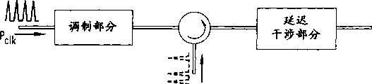
With reference to figure 1, signal is drawn and is possessed the universal concept of the 3R signal regeneration of wavelength Conversion simultaneously on the figure.Specifically, by the effect of 3R regenerator 130, input signal (P
In) 110 be mapped in clock signal (P
Clk) on 120, thus the signal (P of regeneration produced
Reg) 140.From scheming as seen, this notion comprises: shaping again-wherein regenerated signal 140 presents the shape of general clock signal 120; Again regularly-wherein regenerated signal 140 presents the timing of general clock signal 120; And in addition, amplify again-by the effect of amplifier and by optionally choosing clock signal power.
Now, our attentiveness is turned to Fig. 2, draw on the figure according to general 3R signal regenerator 200 of the present invention.Specifically, this 3R regenerator comprises modulating part 210, coupling unit 220 and delayed interference part 230.Correspondingly, input signal (P
In) 240 be added in coupling unit 220 and clock signal (P
Clk) 250 be added in modulating part 210, deliver to delayed interference part 230 then, the output of delayed interference part 230 is the regenerated signal (P that present desirable characteristics
Reg) 260, specifically, present timing and shaping characteristic more exactly.In addition, as previously mentioned, regenerated signal 260 also can select to present wavelength conversion characteristics.
In one embodiment, modulating part 210 comprises energy enable clock signal (P
Clk) 250 the transmission and its refractive index can use input signal (P
In) 240 a kind of medium of modulating or some kinds of different mediums.Certainly, this refractive index can be modulated with change in voltage, variations in temperature or electric current injection by nonlinear effect (i.e. change of refractive in the high light signal).
Obviously, utilizable material has in modulating part 210, as, comprise semiconductor optical amplifier (SOA), absorber, optical fiber, glass, chalcogenide glass, semiconductor, plastic base waveguide material, liquid or gas as InGaAsP, Ga, As or the like.
A kind of implementing method based on SOA (obviously not drawing in Fig. 2) can following work.Input signal (P
In) 240 utilize the refractive index carrier depletion effect of being correlated with, the refractive index of medium in the modulation SOA.Perhaps, can be input signal (P
In) 240 lead-in light electric diodes, produce photoelectric current.Then, this photoelectric current injected SOA or be used to change voltage on the SOA, this voltage changes the carrier density among the SOA again, produces the modulation of refractive index.In another implementing method, according to the input signal (P that applies
In) 240, utilize the Kerr effect to come refractive index in the modulation optical fiber (not shown).The reader reckons with many other implementing methods easily.
Continue with reference to figure 2 now, coupling unit 220 is directly input signal (P
In) 240 introduction modulating part 210, perhaps, in addition, introduce and also revise input signal (P
In) 240, make this signal can be used for changing the refractive index of modulating part 210.In a simple embodiment, coupling unit 220 can comprise optical coupler, input signal (P
In) 240 be coupled into clock signal (P
Clk) 250 passage, it then modulates the refractive index of general nonlinearity material.This simple coupler for example can be placed on before the modulating part 210, or is placed between modulating part 210 and the delayed interference part 230.In another embodiment, coupling unit 220 can comprise the optical circulator that places between modulating part 210 and the delayed interference part 230.In yet another embodiment, coupling unit 220 can comprise the optical photoconductor diode, light input signal (P
In) 240 be converted to signal code.Then, the signal code that obtains is like this introduced modulating part 210, make modulating part 210 produce variations in refractive index.
Continuation is to the discussion of Fig. 2, and delayed interference part 230 comprises optical branching device (not shown), optical combiner (not shown) and a plurality of light path (not shown)s between them.Advantage is that splitter and combiner can be used same device.During operation, with delayed interference part 230 clock signal (P
Clk) 250 being decomposed into two signals, this two signal is along the propagation of interference of light path experience different time then, until the recombinant by the effect of combiner subsequently.Then, this combiner is exported (P interfering (constructive interference or destructive interference) to introduce output
Conv) 260 depend on these two decomposed signals between relative phase relation.If in interference of light path, place a phase shifter and/or a gain/absorption portion, be favourable.Produce the time delay Δ t of these two decomposed signals during by interference of light path from one of two decomposed signals, approximate by Δ t=N Δ t
ClkExpression, N=1 here, 2,3 ..., and the Δ t that introduces here
ClkBasically be the time delay between the clock signal pulse subsequently.
Now our attention is gone to Fig. 3, drawing in a schematic way on the figure shows the device of operation principle of the present invention.Specifically, Fig. 3 3R signal regenerator 300 that draws, it receives λ
1 Input signal P
In310 and λ
2Clock signal P
Clk320 as input, and exports λ subsequently
2Regenerated signal P
Conv330.During operation, input signal P
In310 directly or indirectly modulate the refractive index of modulating part (obviously not drawing on Fig. 3) with one of aforementioned processing way, thus modulation clock signal P
Clk320 phase place.The intensity of variations in refractive index will be fit to make clock signal P
Clk320 amount of phase modulation is approximate greater than zero but be not more than π.The rise time of the phase shift that produces, relevant with used elementary process (for example, carrier depletion, band gap contraction, plasma effect, spectral hole burning, charge carrier heating, two photon absorption ", Kerr effect etc.).Normally by P
InThe pulse-width restricting of 310 signals be bordering on instantaneous process, and the decay of the phase place that produces is slower usually.
After modulating part, P
Clk320 signals are directed into the delayed interference part, are decomposed there, and the recombinant by the effect of splitter 350 and combiner 370 respectively subsequently.The signal that decomposes is crossed at least two paths that separate, or is " arm ", and one comprises delay loop 360, and another comprises phase shifter 365.
Cross shorter interferometer path, present the clock signal of π phase shift, at first arrive coupler and on delivery outlet 380b, " open the switch window ".The clock signal of crossing longer interferometer path arrives after time Δ t, and phase difference is reset, so the switch window in the delivery outlet 380 is closed.If second input data pulse then arranged, then because of the phase place of clock is set in the shorter interferometer path once more, the switch window is opened again.In order to make the clock pulse of sending output subsequently to obtain long mutually basically and the interference that disappears mutually, must selection Δ t time of delay basically with subsequently clock pulse time delay Δ t
ClkIdentical.
Obviously, exist various different ways to realize the coupling unit shown in the reference number 220 among Fig. 2.With reference now to Fig. 4 (a)-(f),, described various realizing method draws on the figure.Fig. 4 (a) draws and places a kind of simple combiner (coupler) 410 of modulating part 420 and delayed interference part 430 fronts.This combiner can be coupled into modulating part to input clock signal and input signal in the co-propagate mode.
Fig. 4 (b) draws and places a kind of coupler 410 between modulating part 420 and the delayed interference part 430.Input signal is introduced in the backpropagation mode.Its advantage is to need not with filter clock to be separated from control signal.In addition, if desired, can use optical isolator at input side.
Fig. 4 (c) comprises circulator 440, places between modulating part 420 and the delayed interference part 430.This circulator 440 is introduced modulating part 420 to input signal.Circulator 440 shines upon into delayed interference part 430 to clock signal undistortedly.
Fig. 4 (d) comprise optical coupler 410 and circulator 440 the two.Clock signal and input signal are introduced through optical coupler 410.This kind configuration supposition is to extract through the circulator 440 that comprises regeneration pulse from the reflection of delayed interference part 430.
The 3R regenerator that Fig. 4 (e) draws and invents in person, it has a grating, and input signal is introduced modulating part 420.This grating can be placed in the optical fiber or in the waveguide, place before or after the modulating part 420.
At last, Fig. 4 (f) comprises photodiode 450, available its detect input signal and produce the electric current (or voltage) of Modulation and Nonlinear medium.Certainly, the one skilled in the art easily sees, also has many other types and variation.
The draw various variations of delayed interference part of 3R regenerator of my invention of Fig. 5 (a)-(e).Obviously, interferometry delay scheme is utilized the light path of different length, perhaps, utilizes the light signal different piece that different propagation velocitys is arranged.These schemes comprise, for example the optical branching device and the combiner of optical coupler form, raster mode, speculum form, polarization splitter form, high-rder mode coupler form.Coupler can have, for example symmetry or asymmetrical shunt ratio, or even tunable.
With reference now to Fig. 5 (a),, interference portion is made of the interference arm of two couplers and two different lengths.In Fig. 5 (c), be two light directing arrangements after the coupler.Light directing arrangement terminates on the reflecting surface, makes light reflected back coupler.Article two, the length of light path is different.In Fig. 5 (d), the interferometer that draws, thereon, a part of light is reflected back with probability R1, and the remainder beam split with probability R2 in that the time is reflected back a little later.Afterwards, this two backward reflecting part interferes, and forms output.At last, at Fig. 5 (e), clock signal is introduced into birefringece crystal or other materials with the polarization state of determining.From this material outgoing, there is the delay of determining with different polarizations in this two signal to each other.Rotate this two signal subsequently, making it becomes identical polarization state and combines, so this two signal can constructive interference or destructive interference.
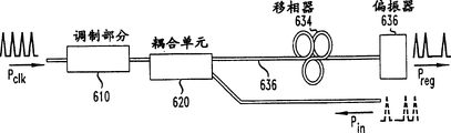
At last, Fig. 6 (a) draws with the 3R regenerator of invention in person of optical fiber realization.Specifically, regenerator 600 comprises modulating part 610, input signal coupling unit and delayed interference part 630, and wherein, delayed interference part 630 has birefringence fiber, phase shifter 634 and polarizer 636.Birefringence fiber 632 can be a polarization mode dispersion optical fiber, and promptly the light to different polarization presents different group velocitys.Delay between the fiber lengths decision is not isotype.As seen,, place phase-shift unit 634 at optical fiber connector away from modulating part 610 at Fig. 6.This phase shifter can be half-wave plate, Polarization Controller or another kind of suitable components.A polarizer is placed in the farther place, and its position is wanted and can be advanced an output being similar to half optical coupling of passing through optical fiber.
In a further embodiment, can insert additional phase shifter, wave plate or polarizer between modulating part and the decay part, thereby guarantee that operation is more stable.In general, recommend a whole unit or its part are carried out temperature control, to guarantee stable operation.Input signal can be coupled into SOA by the backpropagation operational mode.Pei Zhi example is shown in Fig. 6 (b) like this.
The one skilled in the art knows that the present invention can have various other modifications.Thereby all rely on the principle that advanced present technique development and the equivalence narration of this principle basically, but with the inconsistent variation of concrete argumentation of this specification, all should be believed to comprise the present invention illustrated and the scope that in claims, requires within.
Claims (8)
1. the method for an optical regeneration, the step that comprises has:
Use at least one input optical signal and a clock signal, produce the clock signal that phase place and amplitude all are encoded;
Delayed interference part the clock signal of this coding introduction regenerator obtains amplitude-modulated clock signal; With
Export this Modulation and Amplitude Modulation clock signal, existing information in Shu Chu the in store input optical signal of Modulation and Amplitude Modulation clock signal is wherein wherein used this clock signal described at least one input optical signal that allows to retime.
2. according to the process of claim 1 wherein that described delayed interference comprises step:
The clock signal of coding is divided into two light signals at least; With make one of code signal than measuring Δ t another signal delay time, wherein
, Δ t here
ClkBe the clock pulse time delay that between clock signal pulse subsequently, records, and N is an integer.
3. according to the method for claim 2, also comprise step:
Amplitude-modulated clock signal is carried out optics amplifies.
4. according to the method for claim 2, also comprise step:
Make amplitude-modulated clock signal polarization.
5. according to the method for claim 2, delayed interference wherein partly comprises the birefringence fiber of the optical communication that is used to have phase shifter.
6. according to the method for claim 5, delayed interference part wherein also comprises the polarizer of the optical communication that is used to have phase shifter.
7. also comprise step according to the generation step that the process of claim 1 wherein:
Input optical signal is added in the coupling unit of optical regenerator; With
Clock signal is added in the modulating part of optical regenerator.
8. according to the method for claim 7, wherein said coupling unit comprises photodiode.
Applications Claiming Priority (2)
| Application Number | Priority Date | Filing Date | Title |
|---|---|---|---|
| US09/745,785 | 2000-12-22 | ||
| US09/745,785 US6931212B2 (en) | 2000-12-22 | 2000-12-22 | 3R optical signal regeneration |
Publications (2)
| Publication Number | Publication Date |
|---|---|
| CN1360407A CN1360407A (en) | 2002-07-24 |
| CN1242573C true CN1242573C (en) | 2006-02-15 |
Family
ID=24998241
Family Applications (1)
| Application Number | Title | Priority Date | Filing Date |
|---|---|---|---|
| CN01133874.1A Expired - Fee Related CN1242573C (en) | 2000-12-22 | 2001-12-21 | 3R optical signal reproduction |
Country Status (4)
| Country | Link |
|---|---|
| US (1) | US6931212B2 (en) |
| JP (1) | JP4138307B2 (en) |
| CN (1) | CN1242573C (en) |
| CA (1) | CA2363665C (en) |
Families Citing this family (16)
| Publication number | Priority date | Publication date | Assignee | Title |
|---|---|---|---|---|
| US6832053B2 (en) * | 2000-12-22 | 2004-12-14 | Lucent Technologies Inc. | Delayed interference wavelength converter and/or 2R regenerator |
| DE10118958B4 (en) * | 2001-04-10 | 2006-11-09 | Fraunhofer-Gesellschaft zur Förderung der angewandten Forschung e.V. | Optical 3R regenerator with wavelength conversion |
| US7203427B2 (en) * | 2001-05-15 | 2007-04-10 | Alphion Corporation | Redundant path all-optical regeneration, reshaping and wavelength conversion for enhanced yield |
| AUPR673701A0 (en) * | 2001-07-31 | 2001-08-23 | University Of Queensland, The | Optical signal regeneration |
| US7440179B2 (en) * | 2002-05-29 | 2008-10-21 | Alphion Corporation | SOA-MZI device fault isolation |
| US7010234B2 (en) * | 2002-07-29 | 2006-03-07 | Alcatel Optronics Usa, Inc. | All-optical regenerator for retiming, reshaping and retransmitting an optical signal |
| US6798557B1 (en) * | 2003-05-22 | 2004-09-28 | Lucent Technologies Inc. | Direct optical N-state phase shift keying |
| JP4139963B2 (en) * | 2003-02-28 | 2008-08-27 | 日本電気株式会社 | Optical signal regeneration repeater and optical signal regeneration method |
| US6947206B2 (en) * | 2003-07-18 | 2005-09-20 | Kailight Photonics, Inc. | All-optical, tunable regenerator, reshaper and wavelength converter |
| DE10344319A1 (en) * | 2003-09-19 | 2005-04-28 | Fraunhofer Ges Forschung | Wavelength-preserving optical signal regenerator |
| JP2006039037A (en) * | 2004-07-23 | 2006-02-09 | Mitsubishi Electric Corp | Semiconductor optical delay interferometer |
| US7590358B2 (en) * | 2005-02-28 | 2009-09-15 | Vladimir Grigoryan | Optical regenerative amplifier for binary phase shift-keying signals |
| US7489874B2 (en) * | 2005-02-28 | 2009-02-10 | Alcatel-Lucent Usa Inc. | Method and apparatus for demodulation of optical differential phase shift keyed signals |
| WO2009030822A1 (en) * | 2007-09-05 | 2009-03-12 | Luxdyne Oy | Protocol-independent regeneration of optical data signals |
| EP3872464A1 (en) * | 2020-02-28 | 2021-09-01 | FRAUNHOFER-GESELLSCHAFT zur Förderung der angewandten Forschung e.V. | Method for imaging or spectroscopy with a non-linear interferometer |
| CN115308844B (en) * | 2022-07-04 | 2023-11-24 | 厦门市三安集成电路有限公司 | Monolithic integrated chip for multichannel all-optical signal processing and processing method thereof |
Family Cites Families (7)
| Publication number | Priority date | Publication date | Assignee | Title |
|---|---|---|---|---|
| JP3036424B2 (en) * | 1996-01-12 | 2000-04-24 | 日本電気株式会社 | Optical repeater with signal regeneration function |
| GB2320634A (en) * | 1996-12-19 | 1998-06-24 | Northern Telecom Ltd | Optical sampling by using an interferometer to modulate a pulse train |
| JP3438770B2 (en) * | 1998-03-06 | 2003-08-18 | Kddi株式会社 | Optical digital playback device |
| JP2000323786A (en) * | 1999-05-14 | 2000-11-24 | Fujitsu Ltd | Method, device, and system for shaping waveform of signal light |
| JP2001183714A (en) * | 1999-12-27 | 2001-07-06 | Kddi Corp | Optical waveform shaping device |
| US6437905B1 (en) * | 2000-07-07 | 2002-08-20 | Lucent Technologies Inc. | Optical wavelength converter |
| US6832053B2 (en) * | 2000-12-22 | 2004-12-14 | Lucent Technologies Inc. | Delayed interference wavelength converter and/or 2R regenerator |
-
2000
- 2000-12-22 US US09/745,785 patent/US6931212B2/en not_active Expired - Fee Related
-
2001
- 2001-11-22 CA CA002363665A patent/CA2363665C/en not_active Expired - Fee Related
- 2001-12-21 JP JP2001390425A patent/JP4138307B2/en not_active Expired - Fee Related
- 2001-12-21 CN CN01133874.1A patent/CN1242573C/en not_active Expired - Fee Related
Also Published As
| Publication number | Publication date |
|---|---|
| CN1360407A (en) | 2002-07-24 |
| US6931212B2 (en) | 2005-08-16 |
| US20020080453A1 (en) | 2002-06-27 |
| CA2363665A1 (en) | 2002-06-22 |
| JP4138307B2 (en) | 2008-08-27 |
| CA2363665C (en) | 2008-02-05 |
| JP2002207229A (en) | 2002-07-26 |
Similar Documents
| Publication | Publication Date | Title |
|---|---|---|
| CN1242573C (en) | 3R optical signal reproduction | |
| Nakamura et al. | Experimental investigation on high‐speed switching characteristics of a novel symmetric Mach–Zehnder all‐optical switch | |
| JP2629624B2 (en) | All-optical switch | |
| US7068948B2 (en) | Generation of optical signals with return-to-zero format | |
| JPH06326387A (en) | Optical soliton generator | |
| JP4500452B2 (en) | Light modulator | |
| US6882758B2 (en) | Current tuned Mach-Zehnder optical attenuator | |
| Korotky et al. | Fully connectorized high-speed Ti: LiNbO 3 switch/modulator for time-division multiplexing and data encoding | |
| JPH09236835A (en) | Adjustable optical amplitude phase modulator and soliton regenerator containing such modulator | |
| JPH11504773A (en) | Method and apparatus for transmitting a signal in an optical fiber | |
| Park | Accurate determination of transient chirp parameter in high speed digital lightwave transmitters | |
| CN1375957A (en) | Delay interference wavelength conversion and/or 2R regenerator | |
| US6832053B2 (en) | Delayed interference wavelength converter and/or 2R regenerator | |
| US6377388B1 (en) | Optical signal processor | |
| US6512860B2 (en) | Bent electro-absorption modulator | |
| CN113219684A (en) | Acousto-optic modulator | |
| US6498885B1 (en) | Semiconductor nonlinear waveguide and optical switch | |
| EP0455144B1 (en) | An optical polarization modulator employing interferometric structures | |
| JPH07199240A (en) | Optical modulation method | |
| CN1218558A (en) | Optical clock division | |
| Grobkopf et al. | Application of nonlinear effects in semiconductor-laser optical amplifiers | |
| Poberezhskiy et al. | Frequency conversion for WDM applications using polymer traveling-wave electro-optic devices | |
| JPH06118460A (en) | Optical phase modulation circuit | |
| da Silveira | All-Optical Processing Systems Based on Semiconductor Optical Amplifiers | |
| Morimura et al. | The phase reversal effect of a fiber Bragg grating and its application to optical switches |
Legal Events
| Date | Code | Title | Description |
|---|---|---|---|
| C06 | Publication | ||
| PB01 | Publication | ||
| C10 | Entry into substantive examination | ||
| SE01 | Entry into force of request for substantive examination | ||
| C14 | Grant of patent or utility model | ||
| GR01 | Patent grant | ||
| C17 | Cessation of patent right | ||
| CF01 | Termination of patent right due to non-payment of annual fee |
Granted publication date: 20060215 Termination date: 20100121 |