CN1238736C - Polarizer constructions and display devices exhibiting unique color effects - Google Patents
Polarizer constructions and display devices exhibiting unique color effects Download PDFInfo
- Publication number
- CN1238736C CN1238736C CNB008176671A CN00817667A CN1238736C CN 1238736 C CN1238736 C CN 1238736C CN B008176671 A CNB008176671 A CN B008176671A CN 00817667 A CN00817667 A CN 00817667A CN 1238736 C CN1238736 C CN 1238736C
- Authority
- CN
- China
- Prior art keywords
- light
- color
- guest
- polarization state
- transmission
- Prior art date
- Legal status (The legal status is an assumption and is not a legal conclusion. Google has not performed a legal analysis and makes no representation as to the accuracy of the status listed.)
- Expired - Fee Related
Links
Images

Classifications
-
- G—PHYSICS
- G02—OPTICS
- G02B—OPTICAL ELEMENTS, SYSTEMS OR APPARATUS
- G02B5/00—Optical elements other than lenses
- G02B5/30—Polarising elements
-
- G—PHYSICS
- G02—OPTICS
- G02B—OPTICAL ELEMENTS, SYSTEMS OR APPARATUS
- G02B5/00—Optical elements other than lenses
- G02B5/30—Polarising elements
- G02B5/3025—Polarisers, i.e. arrangements capable of producing a definite output polarisation state from an unpolarised input state
-
- G—PHYSICS
- G02—OPTICS
- G02F—OPTICAL DEVICES OR ARRANGEMENTS FOR THE CONTROL OF LIGHT BY MODIFICATION OF THE OPTICAL PROPERTIES OF THE MEDIA OF THE ELEMENTS INVOLVED THEREIN; NON-LINEAR OPTICS; FREQUENCY-CHANGING OF LIGHT; OPTICAL LOGIC ELEMENTS; OPTICAL ANALOGUE/DIGITAL CONVERTERS
- G02F1/00—Devices or arrangements for the control of the intensity, colour, phase, polarisation or direction of light arriving from an independent light source, e.g. switching, gating or modulating; Non-linear optics
- G02F1/01—Devices or arrangements for the control of the intensity, colour, phase, polarisation or direction of light arriving from an independent light source, e.g. switching, gating or modulating; Non-linear optics for the control of the intensity, phase, polarisation or colour
- G02F1/13—Devices or arrangements for the control of the intensity, colour, phase, polarisation or direction of light arriving from an independent light source, e.g. switching, gating or modulating; Non-linear optics for the control of the intensity, phase, polarisation or colour based on liquid crystals, e.g. single liquid crystal display cells
- G02F1/133—Constructional arrangements; Operation of liquid crystal cells; Circuit arrangements
- G02F1/1333—Constructional arrangements; Manufacturing methods
- G02F1/1335—Structural association of cells with optical devices, e.g. polarisers or reflectors
- G02F1/133528—Polarisers
- G02F1/133533—Colour selective polarisers
-
- G—PHYSICS
- G02—OPTICS
- G02F—OPTICAL DEVICES OR ARRANGEMENTS FOR THE CONTROL OF LIGHT BY MODIFICATION OF THE OPTICAL PROPERTIES OF THE MEDIA OF THE ELEMENTS INVOLVED THEREIN; NON-LINEAR OPTICS; FREQUENCY-CHANGING OF LIGHT; OPTICAL LOGIC ELEMENTS; OPTICAL ANALOGUE/DIGITAL CONVERTERS
- G02F1/00—Devices or arrangements for the control of the intensity, colour, phase, polarisation or direction of light arriving from an independent light source, e.g. switching, gating or modulating; Non-linear optics
- G02F1/01—Devices or arrangements for the control of the intensity, colour, phase, polarisation or direction of light arriving from an independent light source, e.g. switching, gating or modulating; Non-linear optics for the control of the intensity, phase, polarisation or colour
- G02F1/13—Devices or arrangements for the control of the intensity, colour, phase, polarisation or direction of light arriving from an independent light source, e.g. switching, gating or modulating; Non-linear optics for the control of the intensity, phase, polarisation or colour based on liquid crystals, e.g. single liquid crystal display cells
- G02F1/133—Constructional arrangements; Operation of liquid crystal cells; Circuit arrangements
- G02F1/1333—Constructional arrangements; Manufacturing methods
- G02F1/1335—Structural association of cells with optical devices, e.g. polarisers or reflectors
- G02F1/133528—Polarisers
- G02F1/133536—Reflective polarizers
-
- G—PHYSICS
- G02—OPTICS
- G02F—OPTICAL DEVICES OR ARRANGEMENTS FOR THE CONTROL OF LIGHT BY MODIFICATION OF THE OPTICAL PROPERTIES OF THE MEDIA OF THE ELEMENTS INVOLVED THEREIN; NON-LINEAR OPTICS; FREQUENCY-CHANGING OF LIGHT; OPTICAL LOGIC ELEMENTS; OPTICAL ANALOGUE/DIGITAL CONVERTERS
- G02F1/00—Devices or arrangements for the control of the intensity, colour, phase, polarisation or direction of light arriving from an independent light source, e.g. switching, gating or modulating; Non-linear optics
- G02F1/01—Devices or arrangements for the control of the intensity, colour, phase, polarisation or direction of light arriving from an independent light source, e.g. switching, gating or modulating; Non-linear optics for the control of the intensity, phase, polarisation or colour
- G02F1/13—Devices or arrangements for the control of the intensity, colour, phase, polarisation or direction of light arriving from an independent light source, e.g. switching, gating or modulating; Non-linear optics for the control of the intensity, phase, polarisation or colour based on liquid crystals, e.g. single liquid crystal display cells
- G02F1/133—Constructional arrangements; Operation of liquid crystal cells; Circuit arrangements
- G02F1/1333—Constructional arrangements; Manufacturing methods
- G02F1/1335—Structural association of cells with optical devices, e.g. polarisers or reflectors
- G02F1/1336—Illuminating devices
- G02F1/133626—Illuminating devices providing two modes of illumination, e.g. day-night
Abstract
A polarizer construction is disclosed that includes a reflective polarizer disposed on a first side of the construction to transmit light having one polarization and reflect light having an orthogonal polarization, and one or more colored dichroic polarizers disposed on a second side of the construction. The one or more colored dichroic polarizers are arranged so that when the construction is illuminated from the first side, an observer viewing the construction from the second side will observe a first spectral distribution of visible light, and when the construction is illuminated from the second side, an observer viewing the construction from the second side will observe a second spectral distribution of visible light different from the first spectral distribution. Various display constructions using colored polarizers to achieve color changing and image reversal effects are also disclosed.
Description
Technical field
The present invention relates generally to colored dichroic polarizers (also claiming polaroid) and their application in electronic display unit.
Background technology
Dichroic material is used for respect to the polarized light on direction of the preferential transmission of the polarized light of other direction.Dichroic material is placed on the light path of a branch of random polarization, and the luminous flux of transmitted light polarized component in one plane maybe can be ignored very for a short time with comparing with the luminous flux of polarized light on the plane of its orthogonal, at this moment to be referred to as be to be subjected to linear polarization to this transmitted light, and this dichroic material layer is referred to as the linear dichroism polaroid.The dichromatism polaroid can be in the spectral range of broad, and in visible light, transmission has the light of specific polarization, it can also by only in the wavelength coverage of restriction transmission have the light of specific polarization to carry out the function of color filter in addition.
A class material that is fit to the generation dichroic effect is the material that a class is called pleochroic dye.The pleochroic dye molecule be optical absorption spectra along with molecule with respect to the orientation of the polarization of incident light and the molecule that changes.Forming one deck on a substrate has the pleochroism dye molecule of orientation can make the branch light polarization plate.The known heterogeneous colours molecule that can be orientated automatically when being used for suitable substrate, as the heterogeneous colours molecule that needs to use some other method for alignment, these methods are such as mixing or producing suitable orientation in conjunction with a kind of host material that is orientated in addition.
The polarized light of the vertical dye molecule orientation of orientation heterogeneous colours common transmission polarization and absorb all other light only meets the dye molecule orientation and has the polarized light of this dye colour can transmission.Because the optical function of most of polaroids is all light that fully stop unwanted polarization direction, single heterogeneous colours is only limited to as polaroid.In polaroid, merge several heterogeneous colourss and can reach polarization more completely, make it cover the major part of visible light, so grey polaroid in for example can producing.Provide required colour filter arbitrarily by a discrete color filter then.
Summary of the invention
To the existing needs of color polarizing plate is the light of a kind of particular color and a kind of polarization to be arranged transmission, and stops all visible lights or a kind of light that the different colours of other polarization is arranged of transmission in fact.According to of the present invention, such polaroid can form pattern and be used as the color filter of an improvement.Also can reach with reflection demonstration, transmission demonstration or reflection and transmission the style color effect is arranged with such polaroid.
According to one aspect of the present invention, provide a kind of polarizer assembly.Described assembly comprises:
Reflection type polarizer, it is positioned at first side of described assembly, is used for transmission and has the light of a polarization state and the light that reflection has an orthogonal polarisation state; With
One or more guest-host polarizers, they are positioned at second side of described assembly;
Wherein, have one in described one or more guest-host polarizers at least and comprise a main matrix, one or more first object dyestuffs and one or more second object dyestuffs, wherein said one or more first object dyestuffs are arranged in described main matrix, be used for absorbing first's visible light with described first polarization state through orientation, described one or more second kind of object dyestuff are arranged in described main matrix, be used to absorb second portion visible light with described second polarization state through orientation, described one or more guest-host polarizers is arranged to be used for second color of light that transmission has first color of light of first polarization state and has second polarization state, described first color is different with second color, and every kind of color all comprises at least a portion visible spectrum, and described first polarization state and second polarization state are mutually orthogonal.
According to another aspect of the present invention, a kind of reflection and transmission type LCD is provided, it comprises:
Backlight;
Liquid crystal material, it is set between a substrate and the bottom substrate, is used for changing selectively the polarisation of light by described liquid crystal material transmission; With
The polarizer assembly of the invention described above, it is set between described backlight and the described bottom substrate, and the reflection type polarizer in the described polarizer assembly is facing to described backlight orientation.
Provide a kind of projector system more on the one hand according to of the present invention, it is characterized in that it comprises:
The projector transmitter is used to launch first spectral distribution with first polarization state and second spectral distribution with second polarization state;
Screen, it is arranged for showing the light of being launched by the projector transmitter; With
One or more color polarizing plates, they are between described screen and described projector transmitter, have one in described one or more guest-host polarizers at least and comprise a main matrix, one or more first object dyestuffs and one or more second object dyestuffs, wherein said one or more first object dyestuffs are arranged in described main matrix, be used for absorbing first's visible light with described first polarization state through orientation, described one or more second kind of object dyestuff are arranged in described main matrix, be used to absorb second portion visible light with described second polarization state through orientation, described one or more color polarizing plate is arranged to be used for the light that described first spectral distribution of transmission has first polarization state, and have the light of second polarization state in described second spectral distribution, and absorb other visible light.
In an example embodiment, the invention provides a kind of guest-host polarizers that includes a main matrix and at least the first and second object dyestuffs are arranged.Configuration first object dyestuff and orientation are absorbed with the first of the visible light of first polarization state in main matrix, and configuration second object dyestuff and orientation are absorbed with the second portion of the visible light of second polarization state vertical with first polarization state in main matrix.
In another example embodiment, the invention provides a kind of reflection and transmission LCD, it comprises backlight, be arranged in the liquid crystal material that selectively changes this place's transmission polarisation of light between face substrate and the bottom substrate, be arranged in reflection and transmission layer between backlight and the liquid crystal material, be arranged in the end polaroid between reflection and transmission layer and the liquid crystal material and be positioned at the face polaroid at vicinal face substrate place.In face polaroid and the end polaroid any or two comprise a guest-host polarizers, guest-host polarizers has a main matrix and is configured in the main matrix and orientation is absorbed with the first one or more object dyestuff of first's visible light of first polarization state, and is configured in the main matrix and orientation is absorbed with the second one or more object dyestuff with the second portion visible light of second polarization state of the first polarization state orthogonal.
In the example embodiment of following, the invention provides the polarizer constructions that comprises a reflecting polarizer and one or more colored dichromatism polaroid.Reflecting polarizer is arranged in a side of this structure, and color polarizing plate is arranged in the opposite side of this structure.Arrange this or more colored dichromatism polaroid, make when first end shines this structure, observe the observer of this structure will observe first spectral distribution of visible light from second end, when second end shines this structure, observe the observer of this structure will observe second spectral distribution of the visible light that is different from first spectral distribution from second end.
In another example embodiment, the invention provides a kind of color liquid crystal material display, it comprises and is arranged in two liquid crystal materials between the parallel display panel substrate, and at least one display panel substrate has been arranged a color filter array.Have at least a color filter to comprise a guest-host polarizers in the color filter, it has a main matrix and is configured in the main matrix and orientation is absorbed with the first one or more object dyestuff of first's visible light of first polarization state, and is configured in the main matrix and orientation is absorbed with the second one or more object dyestuff with the second portion visible light of second polarization state of the first polarization state orthogonal.
In the example embodiment of following, the invention provides a kind of projector system, comprising: a projection transmitter, its launches the light of a kind of and more colors that a polarization state is arranged and the light that one or more other colors of kind of vertical polarization attitude are arranged; Demonstration is by the screen of the light launched of projection transmitter; Be arranged in the color polarizing plate between screen and the projector transmitter.Can arrange the light that same color and polarization are arranged that color polarizing plate comes transmission to launch from the projector transmitter, make the image intensity that produces on the screen can not be polarized sheet and reduce significantly, simultaneously the polaroid light around the filtering also.
In another example embodiment, the invention provides a kind of method of placing polarizer by image.This method comprises provides one a substrate is arranged, a guest-host polarizers transfer layer and be arranged in substrate and the guest-host polarizers transfer layer between the donor element of photo-thermal transfer layer.Then, the transfer layer of donor element is placed on and the place that contacted by main substrate, passes to and be subjected to main substrate from executing the chamber element by the selection zone of executing the chamber element being exposed to the transfer layer that makes a part in the image radiation.At last, from being subjected to main substrate to remove donor element.
Description of drawings
Fig. 1 is the side view that is used for color polarizing plate of the present invention.
Fig. 2 is the side view that comprises the optical texture of a color polarizing plate.
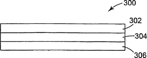
Fig. 3 is the side view that comprises the optical texture of a color polarizing plate.
Fig. 4 is the side view that comprises the display of one or more color polarizing plates.
Fig. 5 is the side view that comprises the display of one or more color polarizing plates.
Fig. 6 is the cross-sectional view strength that comprises the colour liquid crystal display device of one or more color polarizing plates.
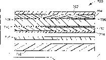
Fig. 7 is the cross-sectional view strength that comprises the colour liquid crystal display device of one or more color polarizing plates.
Fig. 8 is the cross-sectional view strength that comprises the colour liquid crystal display device of one or more color polarizing plates.
Fig. 9 shows the transmitted spectrum of the middle grey polaroid of making according to the present invention.
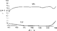
Figure 10 shows the transmitted spectrum of the middle grey polaroid of making according to the present invention.
Describe in detail
Fig. 1 shows the color polarizing plate 100 that uses in the present invention. Color polarizing plate 100 comprises basis The plane of polarization transmission has the single thin layer of the incident light of different spectral characteristics. For example, when polarised light 102 arbitrarily When inciding color polarizing plate 100, transmission has first linear polarization state 104 when first spatial distribution is arranged Light (" ← → " is illustrated in the polarization in the paper plane), and be different from of first spatial distribution having Transmission has the light of vertical linear polarisation attitude 106 (" " expression is perpendicular to the paper plane during two spatial distribution Polarization). The light in the transmitted spectrum of special polarization state is not polarized sheet 100 absorptions basically. For example, Color polarizing plate 100 can transmission have a kind of polarization state a kind of color light with have vertical polarization state in addition A kind of light of color (painted/painted, or dichroism). Also can be made into color polarizing plate 100 can Transmission have a kind of polarization state a kind of color light and basically absorb the visible light be in other polarization state (painted/black). Also can be made into the institute that fully transmission has a kind of polarization state to color polarizing plate 100 Visible light is arranged and basically absorb all visible lights (white/black, or middle ash) that are in other polarization state. Table 1 shows can be by the separately possible face in two kinds of vertical linear polarisation attitudes of polarizer 100 transmissions Colour cell is closed. The present invention has also imagined other color combination that needs.
Table 1 (color combination that " * " expresses possibility)
| Color in the transmission of first polarization state | ||||||||
| Black | Red | Green | Blue | Purple | Blue or green | Yellow | ||
| Color in the transmission of second polarization state | Black | × | × | × | × | × | × | |
| Red | × | × | × | × | × | × | ||
| Green | × | × | × | × | × | × | ||
| Blue | × | × | × | × | × | × | ||
| Purple | × | × | × | × | × | × | ||
| Blue or green | × | × | × | × | × | × | ||
| Yellow | × | × | × | × | × | × | ||
Here used " color " refers to when absorb visible spectrum with one or more of dyestuffs one Thereby or the light time of a kind of color of more part transmission, desired a kind of light less than whole visible spectrum Spectrum distributes. Can be from the context relevant with dyestuff technology is understood the meaning of color. In this, saturating Penetrate a kind of light that only refers to one or more of wavelength in the visible light transmissive spectrum or wavestrip of color, or black Wavelength during visible light transmissive is not composed basically in the situation of look. The special circumstances of black also comprise the dark of grey Shade, here can transmission in a small amount (such as being no more than about 10% or 15%) any or all can See wavelength but also do not cause significantly painted.
The color polarizing plate that the present invention uses can be made by enough diverse ways. Can make one or two Polarization state has all been showed the color polarizing plate of wide region spectral characteristic, and it comprises a main base in a thin layer The object dyestuff of body and at least two types. In an example, a color polarizing plate energy among the present invention Enough comprise a molecular matrix that contains two or more dye molecules, wherein at least a be by one or The heterogeneous colours molecule that a plurality of predetermined directions are arranged is so that incident light depends on the color polarization.
According to the chemical constitution of the particular dye that is oriented, can use molecular matrix that different pleochroisms is dyed Material is along different direction orientations. Can incorporate the combination of different dyes in the dichroism thin layer into, thus can be relatively Selection in molecular matrix makes different dyes directed different. Like this, can use two or more same orientation Or the combination of different orientation dyestuff provides the color polarizing plate of single thin layer, it can be painted/and painted (transmission have a kind of polarization state color light and the light of the color of different polarization states is arranged), painted/black (thoroughly Penetrate a kind of color of light of polarization state and absorb basically all visible lights of other polarization state) or white/ Black (basically all visible lights of a kind of polarization state of transmission and basically absorb all other as seen Light).
Can not use the heterogeneous colours of different orientation, and use of all being arranged on the molecular matrix or One or more heterogeneous colourss of a plurality of no oriented dye and equidirectional orientation change a kind of method and make Color polarizing plate. In such an embodiment, by the optical wavelength that absorbed by the orientation heterogeneous colours or by The optical wavelength that no oriented dye absorbs decides a kind of color of light of polarization, but the color of orthogonal polarized light The optical wavelength that is absorbed by no oriented dye determines. For example, with blue oriented dye and yellow no oriented dye energy Enough make the color polarizing plate of yellow/green, the green of a polarization state is provided when two dyestuffs all are orientated Light only has the weld orientation that the sodium yellow of vertical polarization attitude then is provided.
Use the combination making color polarizing plate that is orientated and does not have oriented dye, higher dye selection spirit can be provided Quick property. For example, in case selected in one application one or more of suitable oriented dye, just can Freely select the dyestuff of one or more of nothing orientations and add this oriented dye group to form multiple color Combination. Do not change the oriented dye of selecting in the application by changing no oriented dye and can access different colours Combination. In addition, especially when needs high-purity dyestuff, no oriented dye more makes in buying.
By coat water-soluble one or more polychrome object dyestuffs and Yi Rong at a solid substrate Liquid crystal material of main part and dry this coating can form as the dichroism of color polarizing plate among the present invention inclined to one side Thin layer shakes. The demonstration substrate comprises glass substrate and hard polymer matrix film, and flexible polymer film, Plural layers, optical laminated, structural membrane or substrate. It is upper useful that the demonstration substrate can also be included in demonstration Other element, such as polarizer, colour filter, black battle array, the electronics addressable is active or passive device (such as thoroughly Prescribed electrode, thin film transistor (TFT)) etc. The demonstration substrate also can comprise the display floater of partially or completely installing.
According to the present invention, guest-host polarizers can be showed the heat resistance of surprising improvement, particularly it is being used When glass substrate. Especially to will be through the structure of heat treatment or to producing the aobvious of heat when the work Show device, heat resistance is very important.
In an example embodiment, molecule or the master of ease of solubility nematic liquid crystal material as guest-host polarizers Matrix. The liquid crystal matrix material that has comprised at least one triazine (triazine) family is particularly useful. When this When the class liquid crystal material was given the identical or different direction of different dyestuffs, they can be used as different object dyestuffs Main body. So suitably select permission dyestuff of transmission different colours on the different polarization plane can produce list The thin layer of one polarization.
When applying a kind of compound main body solution of one or more suitable object dyestuffs, can be to liquid Layer applies to shear and gives the liquid crystal material of main part orderly structure. For fully shearing the aligned liquid-crystal structure Can generate the orientation coating to polychrome object dyestuff orientation, it is generated has dichroism inclined to one side A thin layer of the characteristic of shaking. Because the cutting range degree ratio that coating procedure generates in liquid level can cause just The cutting shearing stress of hard substrate mechanically deform is low, and the process that forms dichromatic layers has the generation of reducing can make substrate The superpotential of the stress that optical characteristics is short. To some specific application, be color such as those substrates that are used for applying The temporary transient carrier of chromatic polarization sheet, or those also need to make substrate along the application of the shear direction orientation that applies, Can use more pliable and tougher substrate and not consider specifically that optical characteristics can variation.
The object dyestuff of particular type can be for generation of dichroic effect, perhaps in limited wave-length coverage Make up other object dyestuff and produce dichroic effect in wider wave-length coverage, for example, they can be used for Grey polarizer or dichroism polarizer in the making. The function of the direction the when orientation of dyestuff generally is coating. The polarizer that the dyestuff of some types is made has in the axis of homology that applies direction, the dyestuff system of other types The polarizer that becomes then has perpendicular to the axis of homology that applies direction. This two classes dyestuff can be at single host and guest's polarization Be used in combination to produce different color combination in the sheet.
Be fit to molecular matrix material of the present invention and comprise United States Patent (USP) 5,948,487 is special with the common U.S. that transfers the possession of The sort of ease of solubility liquid crystal host compound that discloses in the sharp application 09/172,440, the content that discloses is all done For list of references is incorporated herein. Below comprising, the structure of the host compound of implementing is labeled as compd A and change The structure of compound B.

Compd A

Compd B
Dye can be with respect to the master when using in the aqueous solution together with host compound of the present invention Body compound oneself is aimed at, and makes all visible lights of polarization on the parallel plane that applies direction basically logical Cross. These dyestuffs are referred to as parallel colourless property metachromia. A class object dyestuff embodiment who shows by this way Be the triazine dyestuff, generally be referred to as reactive dye. These dyestuffs comprise can be by the conduct of Keystone company Commercially available Reactive Red under the Reactive Red 187 of the active orchil KB supply of material and the some trade marks 120.
Can be with respect to the compound autoregistration so as to make with the plane that applies perpendicular direction in all of polarization can See that the dyestuff that light sees through basically is referred to as vertical colourless property metachromia. Show as a class embodiment of this mode The dyestuff dyestuff (directdye) that is referred to as to lead. Commercial guiding dyestuff has Black RPM (by Crompton﹠ Knowles Colors company provides Charlotte, NC), Black SP (being provided by Keystone company) and (provided by Crompton ﹠ Knowles Colors company, trade mark is Intrajet Yellow to Direct Yellow86 DJR).
By at first preparing water and such as NH
4The pH of OH adjusts compound, can prepare the host and guest's coating solution that has comprised subject and object compound recited above.Guest compound and other adjuvant that can improve the coating ability such as surfactant of dissolving host compound prepare coating solution in aqueous solution then.Can add a small amount of suitable water-soluble copolymer adhesive in main body solution, the weight range that it accounts for is less than 1% to 5% or more.The known polymer that can be used for this purpose comprises dextran type (dextran) polymkeric substance or their sulfate or sulfonated polystyrene.Generally can add a certain amount of host compound and fully form host compound concentration weight ratio, but general suitable concentration range is about 10% to 16% greatly about 8% to 20% aqueous solution.Also can use the main body solution concentration outside this scope to reach needed function degree.For example, the sufficient host and guest's structure that the solution that generates needs to provide after coating sorts as polaroid, and the coating solution that generates needs the aridity that enough concentration provides enough coating thickness, but its concentration is not difficult to orientation after should highly must not being difficult to apply or apply.
Only in selected wavelength coverage, make light polarization if desired, in host and guest's solution, can use single dyestuff.Grey polaroid in providing if desired that is to say that polarized light is roughly the same in whole visible spectrum to such polaroid, at this moment can add several different colours that have in main body solution, but the object dyestuff of same orientation is arranged.Can generate like this is the polaroid of neutral density basically, for example, can add the cyan of similar orientation in main body solution, purplish red and weld forms, also can be with other dye combinations.See through the light and the light that the another kind of color of another kind of polarization is arranged of a kind of color that a kind of polarization is arranged if desired, can use two or more dyestuffs, and wherein have at least two kinds of dyestuffs orientation when applying different.In view of the purpose of this announcement, think that the dyestuff that does not have the dyestuff of orientation and be orientated along a specific direction is the dyestuff of different orientation when applying and shear.
When parallel colourless property metachromia colourlessly is combined into all light of stopping basically on the polarization direction and only during the color polarizing plate by a kind of light of particular color on the vertical polarization, can obtains a kind of useful especially object dye combinations with vertical.For example, can use a kind of compound of suitable vertical colourless object dyestuff to form the light by vertical coating direction but stop the middle grey polaroid of parallel with it light.Equally, can add the parallel colourless property metachromia of particular color in host and guest's combination to, thereby transmission is perpendicular to the light of the particular color that applies the direction polarization.For example, these color polarizing plates can be as the color filter in the colour liquid crystal display device.
The combination of another kind of effectively parallel colourless property metachromia and vertical colourless property metachromia is a kind of combination that forms the dichromatism polaroid, and the transmission of dichromatism polaroid is parallel to the light of a kind of color that applies the direction polarization and the transmission light perpendicular to the another kind of color that applies the direction polarization.For example, the vertical colourless dyestuff that can make up a kind of parallel colourless dyestuff of yellow and a kind of redness in identical main body provides the dichromatism polaroid of single thin layer.As following discussed in detail, can be in transflective liquid crystal display or use the dichromatism polaroid obtain unique effect in conjunction with a reflecting polarizer simply.
The another kind of effectively combination of different orientation dyestuff comprises that one or more of planting no oriented dye together with one or more plant parallel colourless property metachromia or/and one or more plant vertical colourless property metachromia.Such combination not only can be used as the painted/painted polaroid of formation but also can be used for forming painted/black polaroid.
Generally speaking, improve dyestuffs purity and can improve polarization characteristic, because that finds in some commercial dyestuffs can absorb all visible lights of random polarization state such as salt and the such impurity of organic nonionic material, thereby reduced the effect of polaroid, even in the transmission-polarizing attitude, made color filter produce black colourity.According to the weight of providing dyestuff, wish that generally impurity levels in the dyestuff is in 1% scope or lower.The number of the object dye molecule that exists in host and guest's solution can will lack but the object dye molecule cans be compared to host molecule most near the number of main body dyestuff.
Though suitable use in coating procedure is applied to painting method on the coat to some shear stresses, also can be coated to host and guest's solution on the solid substrate with the method for any suitable.The paint-on technique scope that can apply shear stress is from using the extruding dyestuff of wire-wound coated rod to routine.The shear stress that puts on coat in coating procedure can be used to promote the molecular order of guest molecule or host molecule.
The dry coat of the certain methods of available suitable dry water coating, these methods should not damaged coating or upset the molecule order of the coat that is formed by shear stress or other ordering effect.
Use optical graving platemaking technology, hot substance transfer technology and/or other suitable design producing technology on substrate, to form pattern to guest-host polarizers of the present invention.For example, can on a loading substrate, apply the dichromatism polarization layer and form donor element.Then to form the mode of image, make polarization layer by thermal head, induce light or other hot material to be delivered to such as display panel or such being subjected on the main substrate of other suitable substrate from donor element.The hot material Transfer demonstration methods of colored polarization layer from donor element comprises the heat of transmitting photoinduction from donor element, this donor element comprises that basement membrane (generally is the flexible polymer thin layer, such as mylar) photo-thermal transfer layer (generally be radiation absorber, such as carbon black or be distributed in infrared absorbing dye in the bonding agent), selectable middle layer and comprise colored polarization layer transfer layer.As United States Patent (USP) 5,693,446 disclosed like that, make its contact be subjected to main substrate by placing donor unit, and use selection district such as the image radiation source donor element of laser instrument or flashlamp by mask plate, can be by the image transfer polarized material.The content that this patent discloses is drawn and presents as a reference.With more detailed description, form the pattern color polarizing plate and can be used in particular for the color filter of production LCD, and can produce unique change color ability below in a middle one deck color filter of combination and a polaroid function.
Another forms method of patterning and comprises the color polarizing plate selective bleaching, with the dyestuff of one or more kinds of bleaching institute favored area.Like this, institute's favored area of color polarizing plate can be exposed on the solution or material of having bleached one or more kind dyestuffs.For example, color polarizing plate can make a certain dyestuff bleaching on the pattern be formed on the direction of polarized light visible and on another direction of polarized light sightless character or other mark.Can be used for this function such as safety element.
The substrate that is used to apply and/or form the guest-host polarizers of pattern can comprise the substrate that many kinds are suitable.For example, substrate can comprise the substrate of glass or plastics, they can be transparent or partially transparents, it can be painted or brilliant white, can be birefringent or non-birefringent, can comprise the additional optical active layer or do not have, can comprise active or passive electronic or do not comprise, no matter also can comprise being integrated or adding any other thin layer or the material of substrate to, particularly those can be used in influence or control transmission, reflection or absorb thin layer or materials by the light of whole display structures.
In example embodiment, can the pattern electrode transparent conductive oxidation striped of tin indium oxide (ITO) (for example such as) is arranged and/or the matrix of thin film transistor (TFT) (TFT) is arranged or the substrate of other active device on apply guest-host polarizers or form pattern.This comprises and guest-host polarizers is directly applied or forms pattern on the face of electrode and/or TFT, or on the face such as the middle layer of the complanation layer that provides by electrode and/or TFT, or on the opposite side plane on the plane that electrode and/or TFT are arranged on the substrate.As another kind of method, can apply guest-host polarizers or form pattern on the substrate of equipping electrode and/or active device subsequently.No matter polaroid is in the example embodiment that absorb or reflection at other, can apply guest-host polarizers or form pattern in (or comprising on the substrate of polarization layer) on the polaroid.Generally at polaroid or comprised on the structure of polaroid and apply or form pattern, that works according to structure in the required relation of transmission, reflection or absorption axes of one or more polaroid place the axis of homology of guest-host polarizers.
The color polarizing plate of making according to the present invention can be used for multiple optical applications separately or in conjunction with other polaroid and optical element, and is used at multiple display device structure.For example, Fig. 2 shows a suitable layering or other attached to the structure 200 that is used to show purposes on the substrate.Structure 200 comprises selectable surface-treated layer 202, polaroid 204 and optical adhesive 206.According to the present invention, polaroid 204 can be a color polarizing plate.Thin layer 202 can be the surface-treated layer by optics and the selected any appropriate of physical characteristics.For example, thin layer 202 can be anti-reflection coating, nonpolluting coating or other low-energy state coating, or veined or similar coating.When this surface was outside surface, such surface-treated layer was particularly useful.For example, anti-reflection layer and texture layer can help to control reflected light and reduce to glitter.Nonpolluting coating and low-surface-energy attitude coating can make surface easy to clean and raising permanance and treatment characteristic.For example can adhere to hierarchy 200 on substrate or the display panel with selectable adhesive phase 206.Thin layer 206 can be optically transparent pressure sensitive bonding agent, ultraviolet light (uv) solidified liquid bonding agent, hot setting adhesive, high pressure bonding agent, optical scattering bonding agent or similar bonding agent.When under the situation that incides structure 200 at polarized light during utilization structure 200, selectable adhesive phase 206,206 is suitable can to keep the polarization of incident light attitude if use.Structure 200 can be attached on many suitable substrates, and substrate comprises LCD, mirror, reflecting polarizer, dichromatism polaroid, retardation plate or other luminescent system.
A demonstration structure comprises the polaroid 204 that contiguous projector screen (not shown) is placed.Such structure is suitable for the contrast of following the projector emission to use and strengthens screen, such as, it can launch a polarization state one or more plant the light (for example blue light) of colors and another vertical polarization attitude arranged one or more plant the light (for example ruddiness or green glow) of other color.In this example, adjacent transmitters screen place can arrange a color polarizing plate between screen and projector transmitter, and it is designed transmission by the same or similar color of projection transmitter emission and the light of polarization state.Like this, can significantly not reduce to project light intensity on the screen to color polarizing plate as filtering the color filter of a part of ambient light, so improved contrast.
Fig. 3 shows another optical texture 300, and it comprises color polarizing plate 302, selectable adhesive phase 304 and reflection or reflection and transmission layer 306.Selectable adhesive phase 304 can be optically transparent pressure sensitive bonding agent, ultraviolet light (uv) solidified liquid bonding agent, hot setting adhesive, high pressure bonding agent or optical scattering bonding agent.In an example embodiment, adhesive phase 304 has kept the polarisation of light by it basically.Reverberator/reflection and transmission device 306 can be the thin layer of the partial reflection at least of any suitable from the light of the color polarizing plate one side incident of structure 300.For example, reflection horizon 306 can be mirror array, microprism array, holographic reflection and transmission layer of catoptron or irreflexive mirror, partial reflection sheet or partially metallised mirror, reflection multilayer layer, colored mirror, reflecting polarizer, inclination etc.Whole visible spectrums or part spectrum can be selected to reflect basically in reflection horizon 306.The example that can be used for the diffuse reflector of reflectance coating 306 comprises veined metal surface or is dispersed in a mirror thin slice on the optical clear matrix.The example that is applicable to the reflecting polarizer in reflection horizon 306 comprises plurality of layers of double refraction reflecting polarizer, diffuse reflective polarizing sheet and cholesterol polaroid.
The reflecting polarizer as reflection horizon/reflection and transmission layer 306 use of a dichromatism host and guest polaroid 302 of associating can cause unique change color characteristic according to the incident direction of light in structure 300.For example, when from the color polarizing plate unilateral observation, from the front side (observer's one side) illumination the time to can be observed structure 300 are a kind of colors, be another kind of color and can be observed during from back side illumination.By reflecting polarizer as can reflecting the element 306 of a kind of polarization state and other polarization state of transmission, from the polaroid reflection that can be reflected of the light in a kind of polarization state of front side incident, when making proper alignment dichromatism polaroid, can only observe a kind of color.Under opposite situation, from the polaroid transmission that can be reflected of the light in the vertical polarization attitude of rear side incident, thereby light can be observed different colors can be by the transmission of dichromatism polaroid the time.
Such as use reflection and transmission the reflecting polarizer (for example plurality of layers of double refraction reflecting polarizer) of the linearly polarized photon of vertical polarization attitude is arranged, or use reflection and transmission that the cholesterol reflecting polarizer (thinking that dextropolarization is perpendicular to left-hand polarization) of the circularly polarized light of vertical polarization attitude is arranged.Can obtain change color along with the variation of incident light direction.When following colored dichromatism polaroid to use the cholesterol reflecting polarizer to obtain the effect of change color, can between color polarizing plate and cholesterol reflecting polarizer, add a quarter-wave plate and come the light of transmission between cholesterol polaroid and color polarizing plate is converted to linear polarization according to the incident direction of light from circular polarization, and vice versa.
For example, can be in reflection or reflection and transmission LCD optical texture 300 as back side light control element.Can use optically transparent layered adhesive layer (not showing) to come liquid crystal cells is arrived in optical texture 300 combinations and optical coupled.Optical texture 300 can the mode towards liquid crystal cells be attached to liquid crystal cells towards liquid crystal cells or reflection horizon 306 with color polarizing plate 302.
In example embodiment, reflection horizon 306 can be the plurality of layers of double refraction reflecting polarizer or the cholesterol reflecting polarizer of the light of a polarization state of reflection and the light that transmission has a vertical polarization state.When layer 306 is used reflecting polarizer, need be optical texture 300 and liquid crystal cells combination, LCD can also can be used as reflective-mode as transmission mode like that.Use such structure, can obtain effect and unique outward appearance of different-style.For example, can select color polarizing plate 302 to come transmission to have the light (such as ruddiness) of a kind of color of first polarization state and transmission that the light (such as green glow) of the another kind of color of the second vertical polarization state is arranged according to the present invention.For example in transmission mode, when using back side light to throw light on LCD, can use this structure on black background, to show red literal and character.When display used reflective-mode, display can be showed the image of inverse and the color of variation, for example showed the literal or the character of black on the background of green.According to the image inverse of the reflection and transmission LCD of color polarizing plate of the present invention and the notion of change color, it can be generalized to any specific color combinations that is used for character and background, such as the color combination of pointing out in table 1 for use.
The notion of image inverse and change color also can be generalized in the system of the two or more discrete colored dichromatism polaroid that uses a reflecting polarizer (cholesterol or other) and be distributed in the reflecting polarizer same side, wherein selects at least two in the colored dichromatism polaroid to come the different color of transmission and they are arranged to the extinction axis of intersection.In this structure, use the identical change color that two or more solid color dichromatism polaroids can replace using individual layer dichromatism host and guest polaroid to reach aforesaid use individual layer dichromatism host and guest polaroid and the effect of image inverse.So, the present invention has considered that reflecting polarizer of associating uses two or more single color dichromatism polaroids (if desired, can also use described quarter-wave plate) to form the optical texture of showing a kind of polarized light of color and show the polarized light of another kind of color when a side is thrown light on when opposite side throwing light on.For example, this structure can be inserted change color and/or the image complementary picture effect that provides unique in the LCD.
Now, when between reflective-mode and transmission mode, changing, showed that the display of image complementary picture effect accords with to black background bright (in vain) character conversion from bright (in vain) background surplus.Illuminating simultaneously under the situation of this display from front side and rear side, showing that contrast waters down occurring.According to an advantage of dichromatism image inversion of the present invention be to use painted be shown in the painted or painted contrast that is shown in black can be so that be difficult for the influence that watered down by contrast.
Fig. 4 shows the dual-polarization LCD 400 that can comprise according to color polarizing plate of the present invention.LCD 400 can comprise face polaroid 402, selectable delayer or compensator 404, comprises face substrate 406, bottom substrate 410 and be arranged in the liquid crystal cells of the liquid crystal material 408 between them, and end polaroid 412, selectable reflection horizon or reflection and transmission layer 414 and selectable backlight 416.Face polaroid 402 and end polaroid 412 can comprise according to colored polarization layer of the present invention.Can the cremasteric reflex layer or reflection and transmission device 414 allow the illumination environment for use light of LCD 400 or the light of front end optical waveguide (not showing).Can provide selectable backlight 416 to allow under the situation of following or do not follow selectable reflection horizon or reflection and transmission device 414 to LCD 400 backlights.
By using color polarizing plate can access unique style and outward appearance in one or two of the polarizer in LCD 400 402 and 412.For example, polarizer 402 can comprise the colored polarization layer of first color that transmission has first linear polarization and second color that the second vertical linear polarization is arranged.For example, under the situation of ambient light illumination, such structure can be illustrated in the character of first color dyes of display color polaroid transmission on the background of second color dyes of color polarizing plate transmission.Other similar visual effect comprises image inversion effect and colour switching effect, and they can form by the color polarizing plate of the present invention that use is used for polaroid 412 or the light of the polarization state of transmission by being used for reflection horizon 414 and the reflection of light polaroid that reflects another vertical polarization attitude form.
Can be used in single polarizing liquid crystal display device structure according to color polarizing plate of the present invention.Fig. 5 shows single reflection of polarization type LCD 500, it comprises selectable front end optical waveguide 502, front end polaroid 504, selectable retardation plate or compensating plate 506, comprise a face substrate 508, bottom substrate 512 and be arranged in the liquid crystal cells of the liquid crystal material 510 between them, and backside reflection element 514.Use bias light, or when bias light is inadequate, use the selectable additional light source that is used for illuminated displays on the front end optical waveguide 502 reflection LCD 500 that throws light on that is coupling in.Polaroid 504 can comprise according to colored polarization layer of the present invention.Reflection horizon 514 can be the mirror of diffuse reflection or direct reflection, or comprises the partially reflecting layer of partial mirror or colored mirror, or such as the reflection and transmission layer of reflecting polarizer.
By using one to be used for the reflection and transmission layer of element 514 and to provide selectable backlight (not shown) in the behind of reflection and transmission layer 514, LCD 500 also can be used as the reflection and transmission display.In example embodiment, reflection and transmission device 514 can be the reflecting polarizer of polarization state of reflection and transmission vertical polarization attitude, front end polaroid 504 can comprise the one or more transmissions that arranges have first polarization state first color light and the dichromatism polaroid of light of second kind of color of the second vertical polarization attitude is arranged.For example, front end polaroid 504 can comprise dichromatism host and guest polaroid or comprise two dichromatism polaroids that the quadrature extinction axis is arranged.Reflecting polarizer of use such as reflection and transmission layer 514 and dichromatism polaroid or use color polarizing plate can realize unique color effects as front end polaroid 504.For example, come transmission that the blue light and the green glow that the vertical polarization attitude is arranged of polarization state are arranged if arrange polaroid 504, display 500 can have reflecting polarizer 514, make when front end throws light on, display shows as the character that black is arranged on blue background, and when throwing light on from the rear end, display shows as blue character on green background.Use the combination of other different colours to obtain, when between the illumination of front end indirect illumination and rear end transmission mode, changing, can show from black display in painted to the painted display that is shown in painted colour switching and image inverse.
In the reflection and transmission LCD that is similar to structure among Fig. 5 is arranged, can reach the colour switching effect, this structure uses colored backlight source (not shown) to come illuminated displays in transmission mode, it also is useful on the reflecting polarizer of element 514, and the colorama of a polarization state and the colored front end polaroid 504 of all visible lights on another polarization state of transmission basically can transmission be arranged.By selecting can transmission to access the Color Style of uniqueness with the color polaroid 504 of the light of backlight different colours.For example, if backlight sends all visible lights that green glow and color polarizing plate transmission have the blue light of a polarization state and another polarization state is arranged basically, can use this display be illustrated under the reflective-mode (front end illumination) the blue character on the black background and under transmission mode (using the colored backlight source) the green character on black background.As mentioned above, also can use other different color combination and image inverse method.
In the reflection and transmission display, when using the backlight pattern, use the demonstration that reduces that the colored backlight source also can be very big to water down in conjunction with the color polarizing plate among the present invention.When under significant bias light is being arranged, using backlight, between the reflective-mode of the reflection and transmission display that uses the image inverse (reflective-mode shows black and transmission mode shows light, vice versa) and transmission mode, there is competition.Can cause the contrast reduction like this and show that profile waters down.But, can be different because use the color combination of backlight pattern with the color combination of using the front end light illumination mode, use the colored backlight source to offset in conjunction with color polarizing plate and water down effect.When the image inverse, different color combination not necessarily can cause contrast to reduce but can cause the figure image intensifying really.When select to be transmitted in the wavelength bandwidth not with the backlight of the light of the wavelength bandwidth crossover of color polarizing plate transmission the time, the figure image intensifying can be more obvious.
As shown in Figure 1, can be used in display structure shown in Fig. 2-5, make in monochrome or dichromatism show and produce different visual effects according to color polarizing plate of the present invention.In addition, can be used in the elementary or secondary polarizer in the panchromatic LCD or itself be used as color filter according to color polarizing plate of the present invention.When as color filter, the color polarizing plate among the present invention can be used in colour filter function and linear polarization function are merged in the single thin layer or element.The color filter that also can carry out simultaneously polarization function can be removed extra polarization and described enhancing contrast ratio is provided and/or the colour switching characteristic of same or analogous uniqueness is provided.
Referring now to Fig. 6, shown colour liquid crystal display device 600 comprises that face polaroid 602, face substrate 604, face get sentence layer 606, liquid crystal layer 608, the end and get sentence layer 610, colour filter 612, bottom substrate 614, end polaroid 616 and selectable backlight 618.Can comprise color polarizing plate of the present invention with the position grouping of face polaroid 602, end polaroid 616 and/or color filter 612.
Can use the combination and permutation of different colours to color filter array 612.Usually, full-color display is to the primary colours color filter structure of color filter array 612 service regeulations.For example, color filter can be the array of three kinds of colors of rule, generally is redness, green and blueness or cyan, aubergine and yellow.Used color filter can be the color polarizing plate among conventional color filter or the present invention.When in display the present invention in color polarizing plate when the color filter, polaroid should be such type, be a kind of color of a kind of polarization state of transmission, absorb all other colors basically of this polarization state, and basic all light of transmission vertical polarization attitude.Change one type, polaroid should be the light of a transmission a kind of color that a kind of polarization state is arranged and the type that absorbs all other visible lights basically.If color filter 612 is according to the light of a kind of color of transmission first polarization state of the present invention and absorbs the color polarizing plate of other visible light that show contrast though end polaroid 616 can also be used for improving, it is selectable.If color filter 612 is those class color polarizing plates according to basic all visible lights of the light of a kind of color of transmission first polarization state of the present invention and the transmission second vertical polarization attitude, the so suitable back polaroid 616 that uses is particularly when display is used end back lighting 618 from backlight.
Also can allow to form sub-pixel combinations to color polarizing plate as the color filter in the color monitor and improve display resolution.For example, can be in single polarization filter sheet display predetermined colors in combination and green oriented dye, thereby pixel is two subpixel rather than three.Pixel becomes littler and has improved total display effect like this.In identical example, can be used for second kind of subpixel to the polarization filter sheet of blueness in addition, and can form pattern with red/green polarization filter sheet with little overlapping region.The overlapping region is shown as black and can not be used as black matrix.
Optical graving platemaking technology by routine or select for use above-mentioned hot substance transfer technology can make colored guest-host polarizers on display substrate, form pattern and come as color filter.
Except in color filter 612 with color polarizing plate, front end polaroid 602 can comprise according to of the present invention can reach the colored polarization layer that is similar to foregoing various visual effects.Rear end polaroid 616 also can comprise the colored polarization layer that can reach various visual effects according to of the present invention, grey dichromatism polaroid in also can comprising in addition or selectively comprise, such as reflecting polarizer and/or other required element of plurality of layers of double refraction reflecting polarizer.
Fig. 7 shows another colour liquid crystal display device structure 700, it comprises that face substrate 702, colour filter 704, face get sentence layer 706, liquid crystal layer 708, the end and get sentence layer 710, end polaroid 712, bottom substrate 714, selectable reflection horizon, reflection and transmission layer, reflecting polarizer or other optical processing rete 716 and selectable backlight 718.Display 700 has at least two aspects different with the display 600 shown in Fig. 6.The first, colour filter 704 is arranged on the face substrate 702, is arranged on the bottom substrate and figure 6 illustrates colour filter 612.According to special display structure, be arranged in its colour filter and it would be better on the bottom substrate it is arranged in more favourable on the face substrate (vice versa).The second, display 700 comprises the end polaroid 712 of the inboard (liquid crystal side) that is arranged in substrate 714.Color filter 704 can be according to the present invention includes colored polarizer or conventional color filter.End polaroid 712 also can comprise a colored polarization layer of the present invention or conventional dichromatism polaroid.
Fig. 8 shows another colour liquid crystal display device structure 800, it comprises that face substrate 802, face polaroid 804, face get sentence layer 806, liquid crystal layer 808, the end and get sentence layer 810, colour filter 812, bottom substrate 814, selectable optical processing layer or layer group 816 and selectable backlight 818.Display 800 shown in Figure 8 is similar to the display device structure shown in Fig. 7, but color filter 812 shown in Figure 8 is arranged on the bottom substrate 814.
As mentioned above, the color polarizing plate among the present invention can follow other different optical elements to be used for different display structures.A useful especially combination is that color polarizing plate of the present invention adds the dichromatism polaroid, and the axis of homology of dichromatism polaroid is consistent with the axis of homology of colored polarization layer here.Generally speaking, polaroid recently characterizes according to delustring.To a polaroid arbitrarily, it has an axis of homology and an extinction axis, and extinction ratio is the function of wavelength, and it is proportional to and sees through light (being the function of wavelength) divided by seeing through light (being the function of wavelength) along the extinction axis polarization along axis of homology polarization.Extinction ratio can be averaged by for example whole visible spectrum, to reach a numeral ratio.For their dichromatism polaroids of extinction axis aligning separately that makes of a pair of vicinity, total extinction ratio equals their extinction ratios separately and multiplies each other.For example, if the extinction ratio of a guest-host polarizers in certain wavelengths or wavelength coverage among the present invention approximately from 2: 1 to 100: 1, by making the combination of color polarizing plate and conventional polaroid, can improve total extinction ratio of polaroid in the display.
Embodiment
Among the unconfined below embodiment, prepare dye solution by the dyestuff that in the main body aqueous solution, adds various combination.By at first in a certain amount of deionized water, adding such as NH
4The so basic compound of OH is prepared main body solution, is applicable to the basic solution of dissolved compound A or compd B with formation.NH in water
4OH proportion is that 0.5% to 2.0% solution is suitable for dissolved compound A or compd B.Compd A or compd B add in this solution together in company with the surfactant of about 0.1% proportion, and to improve the coating ability of solution, surfactant can be Rohm﹠amp; Haas, Philadelphia, the TritonX-100 that PA sells.Example 1 provides a kind of special main body solution.Other main body solution in the example of back and the main body solution in the example 1 are just in the type of used host compound and quantitatively different.Main body solution in the following example is determined by host compound and concentration.For example, the main body solution of one 16% compd A is meant that the proportion of compd A in main body solution is 16%.Though also can use other concentration, in example, use and the concentration that is suitable for main body solution of the present invention is that per 100 gram water comprise 10 host compounds (9% to 17% solution proportion) that restrain 20 grams.
Embodiment 1
By containing NH at 84 grams
4Dissolving 16 is digested compound A and is contained NH at 84 grams in the aqueous solution of OH
4Dissolving 16 is digested compound B and is prepared main body solution in the same solution of OH.In these solution, add then from Rohm﹠amp; The trade mark that Haas buys is that the proportion of TritonX-100 is 0.1% surfactant, improves the coating ability of solution on polymer substrate.Main body solution hereinafter is to refer to 16% compd A or the solution of B respectively.
Embodiment 2
Prepare the parallel colourless property polaroid (see through the visible light that is parallel to coating direction polarization, and absorb all other visible lights basically) of grey with following method.
Prepare the main body solution of the compd A of 10 grams 16%.Then following composition is added to and form host and guest's solution in the main body solution: the refining ReactiveRedKB (active orchil) (Keystone company) of 0.24 gram, 1.62 gram IntrajetBlueJE liquid (Crompton﹠amp; KnowlesColors company) and the refining ReactiveYellow27 (active yellow dye) (GoldenYellowEG150 of Keystone company) of 0.20 gram.Host and guest's solution cutting (shear) is coated on the plastic base about 13 microns of its wet thickness.Dry coating, and use spectrophotometer to measure the transport property of polaroid in visible spectrum (400nm is to 700nm) scope.Fig. 9 has shown the transmitted spectrum 900 that is parallel to the polarized light that applies direction and perpendicular to the transmitted spectrum 902 of the polarized light that applies direction.Use the main body solution of 16% compd B to prepare the parallel colourless polaroid of another grey with same method.Similar among resulting transmitted spectrum and Fig. 9.
Embodiment 3
Prepare the vertical colourless property polaroid (see through, and all other visible lights of basic absorption) of grey perpendicular to the visible light that applies the direction polarization with following method.
Prepare the main body solution of the compd A of 10 grams 16%.Then following composition is added in the main body solution to make host and guest's solution: the refining IntrajetBlackRPM (Crompton﹠amp of 0.1 gram; Knowles company), 0.03 gram IntrajetBlueJE liquid (Crompton﹠amp; Knowles company) and 0.12 gram IntrajetYellowDJR liquid (Crompton﹠amp; Knowles company).The cutting of host and guest's solution is coated on the sample 2.Dry coating, and measure the transport property of polaroid in limit of visible spectrum.Figure 10 has shown the transmitted spectrum 1000 and the transmitted spectrum 1002 that is parallel to the polarized light that applies direction perpendicular to the polarized light that applies direction.In kind use the main body solution of 16% compd B to prepare the vertical colourless property polaroid of another grey.Similar among resulting transmitted spectrum and Figure 10.
Embodiment 4
Do not make up and make a green/black color polarizing plate by will have oriented dye and oriented dye in molecular matrix, it is by following weight ratio:
1.5 part compd A or B
0.6 part ammonium hydroxide
7 parts of water
0.1 the blue triarylmethane dye (C.I.FoodBlue2 is provided by Warner Jenkinson company commerce) of part nothing orientation
0.1 part IntrajetBlueJE (Crompton﹠amp; KnowlesColors company)
0.3 part KeyreactRedKB (Keystone company)
0.1 part KeystoneYellowEG150 (Keystone company)
0.2 part DirectYellowDJR (Crompton﹠amp; KnowlesColors company)
In the time of on being coated to glass substrate, this composition has just produced a transmission to be had a green glow of a polarization state and not to transmit color polarizing plate perpendicular to any light of polarization state basically.
Adopt other not have the orientation blue active dye,, replace above-mentioned nothing orientation blue active dye (C.I.FoodBlue2) also can make similar color polarizing plate such as the methyl blue dyes in the dyestuff of thiazine (thiazine) family.
Embodiment 5,6 and 7
Will be according to embodiment 5,6, and/or the color polarizing plate of made is combined into chromatic color filter and can makes such as Fig. 6 in 7, desired display in 7 and 8.
Embodiment 5
The transmission-type host and guest color polarizing plate (transmission is parallel to the cyan light that applies direction and absorbs all other visible lights basically) that can prepare cyan by the combination of following composition (providing) in the solution by weight:
The main body solution of 20 parts 16% compd B
0.8 the BlackRPM (Crompton﹠amp of part; Knowles company)
0.2 part YellowDJR (Crompton﹠amp; Knowles company)
2.5 part BlueJE (Crompton﹠amp; Knowles company)
Host and guest's solution is coated on the glass substrate, and wet thickness is 25 microns, and the dry transmission-type chromatic color filter of making a cyan.
Embodiment 6
Combination by following composition in the solution can prepare purpureal transmission-type host and guest color polarizing plate (transmission is parallel to the purple light that applies direction and absorbs all other visible lights basically):
The main body solution of 20 parts 16% compd B
0.8 the BlackRPM (Crompton﹠amp of part; Knowles company)
0.2 part YellowDJR (Crompton﹠amp; Knowles company)
0.24 part ReactiveRedKB (Keystone company)
Host and guest's solution is coated on the glass substrate, and wet thickness is 25 microns, and drying is made a purpureal transmission-type chromatic color filter.
Embodiment 7
Combination by following composition in the solution can prepare yellow transmission-type host and guest color polarizing plate (transmission is parallel to the sodium yellow that applies direction and absorbs all other visible lights basically):
The main body solution of 20 parts 16% compd B
0.8 the BlackRPM (Crompton﹠amp of part; Knowles company)
0.2 part YellowDJR (Crompton﹠amp; Knowles company)
0.2 part GoldenYellowEG150 (Keystone company)
Host and guest's solution is coated on the glass substrate, and wet thickness is 25 microns, and the dry transmission-type chromatic color filter of making a yellow.
Embodiment 8
Can make the donor element of photoinduction thermal cross over color polarizing plate according to the present invention.Method is: the photothermal transformation layer that applies 2 micron thickness that contain the carbon black that is dispersed on the thermoplastic adhesives on polyethylene terephthalate (PET) substrate of 100 micron thickness, on photothermal transformation layer, apply the Polymer interlayers of 1.5 micron thickness, on middle layer, apply host and guest's solution of the cyan of embodiment 4 as the conversion layer of donor element.The guest-host polarizers conversion layer to 2 of dry cyan is to 5 micron thickness.
Donor element is placed on glass is subjected on the main substrate and the cyan conversion layer is being contacted to be subjected to main substrate, donor element is by the vacuum fixed position.When the 1064nm light of donor element by the Nd:YAg laser instrument used 140 microns to 150 microns beam spot size and 8 watts of energy and variable residence time imaging, the striped of color polarizing plate conversion layer became being transformed into from donor element of image to be subjected to main stor(e)y.
Claims (10)
1. a polarizer assembly is characterized in that, described assembly comprises:
Reflection type polarizer, it is positioned at first side of described assembly, is used for transmission and has the light of a polarization state and the light that reflection has an orthogonal polarisation state; With
One or more guest-host polarizers, they are positioned at second side of described assembly;
Wherein, have one in described one or more guest-host polarizers at least and comprise a main matrix, one or more first object dyestuffs and one or more second object dyestuffs, wherein said one or more first object dyestuffs are arranged in described main matrix, be used for absorbing first's visible light with described first polarization state through orientation, described one or more second kind of object dyestuff are arranged in described main matrix, be used to absorb second portion visible light with described second polarization state through orientation, described one or more guest-host polarizers is arranged to be used for second color of light that transmission has first color of light of first polarization state and has second polarization state, described first color is different with second color, and every kind of color all comprises at least a portion visible spectrum, and described first polarization state and second polarization state are mutually orthogonal.
2. polarizer assembly as claimed in claim 1 is characterized in that, described one or more guest-host polarizers comprise first guest-host polarizers and second guest-host polarizers, and they are configured to have the extinction axis of intersection.
3. polarizer assembly as claimed in claim 1 is characterized in that, described reflection type polarizer is a plurality of layers of double refraction reflection type polarizer.
4. polarizer assembly as claimed in claim 1, it is characterized in that, described reflection type polarizer is a cholesterol reflection type polarizer, and described polarizer assembly also comprises a quarter-wave plate, and it is between described cholesterol reflection type polarizer and described one or more guest-host polarizers.
5. polarizer assembly as claimed in claim 1 is characterized in that, also comprises a kind of bonding agent, and described bonding agent is between described reflection type polarizer and described one or more guest-host polarizers.
6. polarizer assembly as claimed in claim 5 is characterized in that described bonding agent is a kind of diffuse adhesives, is used to keep the polarisation of light by described bonding agent transmission.
7. polarizer assembly as claimed in claim 1 is characterized in that, also comprises a delayer, and it is between described reflection type polarizer and described one or more guest-host polarizers.
8. polarizer assembly as claimed in claim 1, it is characterized in that, also comprise a kind of liquid crystal material, described liquid crystal material and is configured to change selectively polarisation of light by described liquid crystal material transmission between described reflection type polarizer and described one or more guest-host polarizers.
9. reflection and transmission type LCD is characterized in that it comprises:
Backlight;
Liquid crystal material, it is set between a substrate and the bottom substrate, is used for changing selectively the polarisation of light by described liquid crystal material transmission; With
Polarizer assembly as claimed in claim 1, it is set between described backlight and the described bottom substrate, and the reflection type polarizer in the described polarizer assembly is facing to described backlight orientation.
10. projector system is characterized in that it comprises:
The projector transmitter is used to launch first spectral distribution with first polarization state and second spectral distribution with second polarization state;
Screen, it is arranged for showing the light of being launched by the projector transmitter; With
One or more guest-host polarizers, they are between described screen and described projector transmitter, have one in described one or more guest-host polarizers at least and comprise a main matrix, one or more first object dyestuffs and one or more second object dyestuffs, wherein said one or more first object dyestuffs are arranged in described main matrix, be used for absorbing first's visible light with described first polarization state through orientation, described one or more second kind of object dyestuff are arranged in described main matrix, be used to absorb second portion visible light with described second polarization state through orientation, described one or more guest-host polarizers is arranged to be used for the light that described first spectral distribution of transmission has first polarization state, and have the light of second polarization state in described second spectral distribution, and absorb other visible light.
Applications Claiming Priority (2)
| Application Number | Priority Date | Filing Date | Title |
|---|---|---|---|
| US09/426,461 | 1999-10-25 | ||
| US09/426,461 US6574044B1 (en) | 1999-10-25 | 1999-10-25 | Polarizer constructions and display devices exhibiting unique color effects |
Publications (2)
| Publication Number | Publication Date |
|---|---|
| CN1433522A CN1433522A (en) | 2003-07-30 |
| CN1238736C true CN1238736C (en) | 2006-01-25 |
Family
ID=23690898
Family Applications (1)
| Application Number | Title | Priority Date | Filing Date |
|---|---|---|---|
| CNB008176671A Expired - Fee Related CN1238736C (en) | 1999-10-25 | 2000-02-29 | Polarizer constructions and display devices exhibiting unique color effects |
Country Status (8)
| Country | Link |
|---|---|
| US (3) | US6574044B1 (en) |
| EP (1) | EP1226459B1 (en) |
| JP (1) | JP2003513299A (en) |
| KR (1) | KR20020053827A (en) |
| CN (1) | CN1238736C (en) |
| AU (1) | AU3714400A (en) |
| DE (1) | DE60007654T2 (en) |
| WO (1) | WO2001031371A1 (en) |
Families Citing this family (79)
| Publication number | Priority date | Publication date | Assignee | Title |
|---|---|---|---|---|
| DE69435174D1 (en) | 1993-12-21 | 2009-01-15 | Minnesota Mining & Mfg | Multilayer optical film |
| US6096375A (en) * | 1993-12-21 | 2000-08-01 | 3M Innovative Properties Company | Optical polarizer |
| US6574044B1 (en) * | 1999-10-25 | 2003-06-03 | 3M Innovative Properties Company | Polarizer constructions and display devices exhibiting unique color effects |
| JP2001174633A (en) * | 1999-12-15 | 2001-06-29 | Nitto Denko Corp | Polarizing member and liquid crystal display device |
| JP2003521742A (en) * | 2000-02-03 | 2003-07-15 | ロリク アーゲー | Color switch |
| JP3858581B2 (en) * | 2000-09-26 | 2006-12-13 | セイコーエプソン株式会社 | Liquid crystal device and electronic device |
| EP1237207B1 (en) * | 2001-03-02 | 2012-01-04 | FUJIFILM Corporation | Method for producing organic thin film device |
| US7106307B2 (en) * | 2001-05-24 | 2006-09-12 | Eastman Kodak Company | Touch screen for use with an OLED display |
| US6642977B2 (en) | 2001-06-20 | 2003-11-04 | 3M Innovative Properties Company | Liquid crystal displays with repositionable front polarizers |
| US7110178B2 (en) * | 2001-07-02 | 2006-09-19 | 3M Innovative Properties Company | Polarizers coated with optically functional layers |
| TW557371B (en) * | 2001-07-02 | 2003-10-11 | Sumitomo Chemical Co | Semi-transparent-semi-reflectivity film, semi- transparent-semi-reflectivity polarized film, polarized light device using these films, and liquid crystal display device using these films |
| RU2226708C2 (en) * | 2001-09-21 | 2004-04-10 | ОПТИВА, Инк. | Liquid-crystal display with reflection polarizer |
| KR100883986B1 (en) * | 2002-07-09 | 2009-02-17 | 엘지디스플레이 주식회사 | LCD with CLC color filter and CLC polariser |
| DE10233734A1 (en) * | 2002-07-24 | 2004-02-05 | Siemens Ag | Mirror with display device especially for motor vehicles has a liquid crystal cell with rear polarized foil and a front polarizing filter |
| AU2003270750A1 (en) * | 2002-09-20 | 2004-04-08 | Honeywell International, Inc. | High efficiency viewing screen |
| US6908202B2 (en) | 2002-10-03 | 2005-06-21 | General Electric Company | Bulk diffuser for flat panel display |
| US7271863B2 (en) * | 2002-10-16 | 2007-09-18 | Nitto Denko Corporation | Color liquid crystal display with internal rear polarizer |
| US6879356B2 (en) * | 2003-01-06 | 2005-04-12 | Industrial Technology Research Institute | Optical device having an E-mode polarizer |
| US7048307B1 (en) * | 2003-03-14 | 2006-05-23 | Serigraph, Inc. | Reflective display |
| KR20060054371A (en) * | 2003-07-31 | 2006-05-22 | 쓰리엠 이노베이티브 프로퍼티즈 컴파니 | Compositions for encapsulation and controlled release |
| US7479938B2 (en) * | 2003-09-19 | 2009-01-20 | Hewlett-Packard Development Company, L.P. | Optically addressable display and method driven by polarized emissions |
| TW594275B (en) * | 2003-10-22 | 2004-06-21 | Optimax Tech Corp | A method of enhancing contrast ratio |
| KR100910954B1 (en) * | 2003-10-23 | 2009-08-05 | 닛토덴코 가부시키가이샤 | Optical element, condensing backlight system and liquid crystal display unit |
| TWI234014B (en) * | 2004-03-19 | 2005-06-11 | Optimax Tech Corp | Structure and generated method of a polarizer with improved the view angle |
| US7379135B2 (en) * | 2004-05-28 | 2008-05-27 | Fujitsu Limited | Transflective liquid crystal display |
| JP2006077151A (en) * | 2004-09-10 | 2006-03-23 | Fuji Photo Film Co Ltd | Liquid crystal composition and liquid crystal element |
| US7338690B2 (en) * | 2004-09-17 | 2008-03-04 | Fujifilm Corporation | Liquid crystal composition and liquid crystal device |
| JP2006126371A (en) * | 2004-10-27 | 2006-05-18 | Nissan Motor Co Ltd | Dimmer material, vehicle using same, and method for manufacturing dimmer material |
| US20060110540A1 (en) * | 2004-11-24 | 2006-05-25 | 3M Innovative Properties Company | Method for making nanostructured surfaces |
| US7582330B2 (en) * | 2004-11-24 | 2009-09-01 | 3M Innovative Properties Counsel | Method for making metallic nanostructures |
| US7247723B2 (en) * | 2004-11-24 | 2007-07-24 | 3M Innovative Properties Company | Metallic chromonic compounds |
| US7687115B2 (en) * | 2004-11-24 | 2010-03-30 | 3M Innovative Properties Company | Method for making nanostructured surfaces |
| DE602005006508D1 (en) * | 2004-12-07 | 2008-06-19 | Merck Patent Gmbh | Polymerizable liquid crystal compositions and polarizer |
| US7286192B2 (en) * | 2005-06-07 | 2007-10-23 | Au Optronics Corporation | Transflective liquid crystal display |
| US7768604B2 (en) * | 2005-09-20 | 2010-08-03 | Au Optronics Corporation | Transflective liquid crystal display with partially shifted reflectivity curve |
| US7718716B2 (en) * | 2005-10-14 | 2010-05-18 | 3M Innovative Properties Company | Chromonic nanoparticles containing bioactive compounds |
| US7629027B2 (en) * | 2005-10-14 | 2009-12-08 | 3M Innovative Properties Company | Method for making chromonic nanoparticles |
| TWI275876B (en) * | 2005-10-28 | 2007-03-11 | Jemitek Electronics Corp | Dual panel display |
| US20070128291A1 (en) * | 2005-12-07 | 2007-06-07 | Tokie Jeffrey H | Method and Apparatus for Forming Chromonic Nanoparticles |
| US7807661B2 (en) | 2005-12-08 | 2010-10-05 | 3M Innovative Properties Company | Silver ion releasing articles and methods of manufacture |
| US20070146481A1 (en) * | 2005-12-12 | 2007-06-28 | Volkswagen Ag | Rear view mirror for a motor vehicle |
| US8092710B2 (en) * | 2005-12-19 | 2012-01-10 | 3M Innovative Properties Company | Hierarchical chromonic structures |
| US7601769B2 (en) * | 2005-12-19 | 2009-10-13 | 3M Innovative Peroperties Company | Multilayered chromonic structures |
| US20070139766A1 (en) * | 2005-12-20 | 2007-06-21 | Radcliffe Marc D | High contrast front projection screen |
| US7824732B2 (en) | 2005-12-28 | 2010-11-02 | 3M Innovative Properties Company | Encapsulated chromonic particles |
| US7683988B2 (en) * | 2006-05-10 | 2010-03-23 | Au Optronics | Transflective liquid crystal display with gamma harmonization |
| US8068605B2 (en) * | 2006-03-07 | 2011-11-29 | Sony Ericsson Mobile Communications Ab | Programmable keypad |
| US20070229733A1 (en) * | 2006-04-03 | 2007-10-04 | Duck-Jong Suh | Liquid crystal display, panel for the same and method of manufacture |
| US7317576B2 (en) * | 2006-04-21 | 2008-01-08 | Cpfilms, Inc. | Dichroic filters on flexible polymer film substrates |
| US20080030656A1 (en) * | 2006-08-01 | 2008-02-07 | 3M Innovative Properties Company | Transflective lc display with internal reflector and reflective polarizer |
| US7826009B2 (en) | 2006-12-21 | 2010-11-02 | 3M Innovative Properties Company | Hybrid polarizer |
| US20080204463A1 (en) * | 2007-02-27 | 2008-08-28 | Adam Cybart | Adaptable User Interface and Mechanism for a Title Portable Electronic Device |
| US20080207254A1 (en) * | 2007-02-27 | 2008-08-28 | Pierce Paul M | Multimodal Adaptive User Interface for a Portable Electronic Device |
| US20080204418A1 (en) * | 2007-02-27 | 2008-08-28 | Adam Cybart | Adaptable User Interface and Mechanism for a Portable Electronic Device |
| US20080204417A1 (en) * | 2007-02-27 | 2008-08-28 | Pierce Paul M | Multimodal Adaptive User Interface for a Portable Electronic Device |
| US8902152B2 (en) * | 2007-04-30 | 2014-12-02 | Motorola Mobility Llc | Dual sided electrophoretic display |
| US20080291169A1 (en) * | 2007-05-21 | 2008-11-27 | Brenner David S | Multimodal Adaptive User Interface for a Portable Electronic Device |
| US20080309589A1 (en) * | 2007-06-13 | 2008-12-18 | Morales Joseph M | Segmented Electroluminescent Device for Morphing User Interface |
| US9122092B2 (en) * | 2007-06-22 | 2015-09-01 | Google Technology Holdings LLC | Colored morphing apparatus for an electronic device |
| US20090041984A1 (en) * | 2007-08-10 | 2009-02-12 | Nano Terra Inc. | Structured Smudge-Resistant Coatings and Methods of Making and Using the Same |
| US20090042619A1 (en) * | 2007-08-10 | 2009-02-12 | Pierce Paul M | Electronic Device with Morphing User Interface |
| US8077154B2 (en) * | 2007-08-13 | 2011-12-13 | Motorola Mobility, Inc. | Electrically non-interfering printing for electronic devices having capacitive touch sensors |
| US8139195B2 (en) * | 2007-12-19 | 2012-03-20 | Motorola Mobility, Inc. | Field effect mode electro-optical device having a quasi-random photospacer arrangement |
| KR20090080370A (en) * | 2008-01-21 | 2009-07-24 | 삼성전자주식회사 | Polarizer and display device having the same |
| US8059232B2 (en) * | 2008-02-08 | 2011-11-15 | Motorola Mobility, Inc. | Electronic device and LC shutter for polarization-sensitive switching between transparent and diffusive states |
| US7864270B2 (en) * | 2008-02-08 | 2011-01-04 | Motorola, Inc. | Electronic device and LC shutter with diffusive reflective polarizer |
| JP4961581B2 (en) * | 2008-02-14 | 2012-06-27 | 富士フイルム株式会社 | Display device |
| WO2010078066A1 (en) * | 2008-12-31 | 2010-07-08 | 3M Innovative Properties Company | Polarizing device for selectively blocking and transmitting radiation and method making same |
| JP2010250025A (en) * | 2009-04-14 | 2010-11-04 | Hitachi Displays Ltd | Polarization element, method for manufacturing the same, and liquid crystal display |
| KR101676313B1 (en) | 2010-05-31 | 2016-11-16 | 삼성디스플레이 주식회사 | Organic light emitting device |
| WO2012070904A2 (en) * | 2010-11-25 | 2012-05-31 | Choi Uk | Polarized light illumination system |
| CN103246104B (en) * | 2012-02-14 | 2017-09-26 | 日本精机株式会社 | Liquid crystal display device |
| CN103869519B (en) * | 2012-12-13 | 2016-06-01 | 京东方科技集团股份有限公司 | Manufacture the method for Thin Film Transistor-LCD |
| KR101640670B1 (en) * | 2013-09-30 | 2016-07-18 | 주식회사 엘지화학 | Optical element |
| US9618669B2 (en) | 2013-11-08 | 2017-04-11 | Apple Inc. | Electronic device display with polarizer windows |
| JP2016142942A (en) * | 2015-02-03 | 2016-08-08 | 住友化学株式会社 | Polarizing plate, liquid crystal panel and liquid crystal display device |
| CN104614895A (en) * | 2015-03-05 | 2015-05-13 | 京东方科技集团股份有限公司 | Illumination and display device |
| US20170153496A1 (en) * | 2015-08-11 | 2017-06-01 | Shenzhen China Star Optoelectronics Technology Co. Ltd. | Manufacture method of polarization and color filter function integration film and liquid crystal display panel |
| WO2022168709A1 (en) * | 2021-02-05 | 2022-08-11 | 日本ゼオン株式会社 | Optical laminate and method for determining authenticity thereof, and article |
Family Cites Families (40)
| Publication number | Priority date | Publication date | Assignee | Title |
|---|---|---|---|---|
| US2400877A (en) | 1941-03-21 | 1946-05-28 | John F Dreyer | Optical device and method and manufacture thereof |
| US2544659A (en) | 1946-05-14 | 1951-03-13 | John F Dreyer | Dichroic light-polarizing sheet materials and the like and the formation and use thereof |
| US4031092A (en) | 1975-06-16 | 1977-06-21 | Minnesota Mining And Manufacturing Company | 1,3-Bis-(carboxy-phenylamino)-s-triazines |
| US4030812A (en) | 1975-06-16 | 1977-06-21 | Minnesota Mining And Manufacturing Company | Lyotropic birefringent films |
| US4634225A (en) * | 1984-12-24 | 1987-01-06 | General Electric Co. | Transflective liquid crystal display with integral heating unit and temperature sensor |
| JPS6269202A (en) | 1985-09-20 | 1987-03-30 | Fuji Photo Film Co Ltd | Polarizing film |
| JP2675158B2 (en) | 1988-12-07 | 1997-11-12 | シャープ株式会社 | Liquid crystal display |
| DE69020855T2 (en) | 1989-03-28 | 1996-03-28 | Asahi Glass Co Ltd | LIQUID CRYSTAL DISPLAY DEVICE. |
| NL8901167A (en) | 1989-05-10 | 1990-12-03 | Philips Nv | METHOD FOR MANUFACTURING A POLARIZATION FILTER, A POLARIZATION FILTER SO OBTAINED AND A DISPLAY EQUIPPED WITH THE POLARIZATION FILTER. |
| JP2631015B2 (en) | 1989-06-06 | 1997-07-16 | 株式会社リコー | Liquid crystal polymer alignment method |
| US5235449A (en) | 1990-03-02 | 1993-08-10 | Hitachi, Ltd. | Polarizer with patterned diacetylene layer, method for producing the same, and liquid crystal display device including such polarizer |
| US5380459A (en) | 1990-04-20 | 1995-01-10 | Ricoh Company, Ltd. | Liquid crystal display device with improved viewing angle dependence of color |
| US5526150A (en) | 1991-07-19 | 1996-06-11 | Nippon Oil Company, Limited | Liquid crystal polymer viewing angle compensator for liquid crystal display having its largest refractive index in the thickness direction |
| DE59310312D1 (en) * | 1992-07-01 | 2002-12-12 | Forschungszentrum Juelich Gmbh | METHOD FOR PRODUCING SACCHAROSE SYNTHASE |
| DE69319215T2 (en) | 1992-12-25 | 1998-10-22 | Mitsui Chemicals Inc | Polarizing color filter |
| JPH06300916A (en) | 1993-04-12 | 1994-10-28 | Sumitomo Chem Co Ltd | Production of phase difference film |
| JP2693368B2 (en) | 1993-06-29 | 1997-12-24 | スタンレー電気株式会社 | Liquid crystal display device and method of manufacturing the same |
| JP3284002B2 (en) | 1993-11-22 | 2002-05-20 | 富士写真フイルム株式会社 | Elliptical polarizing plate and liquid crystal display device using the same |
| JPH07318926A (en) | 1994-05-25 | 1995-12-08 | Fuji Xerox Co Ltd | Reflection type liquid crystal display device |
| US5521035A (en) | 1994-07-11 | 1996-05-28 | Minnesota Mining And Manufacturing Company | Methods for preparing color filter elements using laser induced transfer of colorants with associated liquid crystal display device |
| US5751389A (en) | 1994-09-08 | 1998-05-12 | Sumitomo Chemical Company | Film containing oriented dye, method of manufacturing the same, and polarizer and liquid crystal display unit utilizing the same |
| US5589963C1 (en) | 1994-09-30 | 2001-06-26 | Rockwell International Corp | Pixelated compensators for twisted nematic liquid crystal displays |
| EP1158320B1 (en) | 1994-11-18 | 2008-08-06 | Nitto Denko Corporation | Dichroic light polarizers |
| US6707516B1 (en) * | 1995-05-23 | 2004-03-16 | Colorlink, Inc. | Single-panel field-sequential color display systems |
| JP3557290B2 (en) | 1995-04-11 | 2004-08-25 | 富士写真フイルム株式会社 | Optical compensation sheet, method for manufacturing the same, liquid crystal display device, and color liquid crystal display device |
| US5672296A (en) | 1995-06-02 | 1997-09-30 | Hoechst Celanese Corp. | Polarizer films comprising wholly aromatic liquid crystalline polymers and dichroic dyes |
| GB2306231A (en) | 1995-10-13 | 1997-04-30 | Sharp Kk | Patterned optical polarising element |
| US5610743A (en) | 1995-10-30 | 1997-03-11 | United Microelectronics Corporation | Liquid crystal display including concentric shapes and radial spokes which has an improved viewing angle |
| EP0803077B1 (en) | 1995-11-13 | 2004-12-01 | Koninklijke Philips Electronics N.V. | Picture display device |
| RU2120651C1 (en) | 1996-04-15 | 1998-10-20 | Поларайзер Интернэшнл, ЛЛСи | Lcd indicator |
| US5693446A (en) | 1996-04-17 | 1997-12-02 | Minnesota Mining And Manufacturing Company | Polarizing mass transfer donor element and method of transferring a polarizing mass transfer layer |
| AU6508898A (en) | 1997-03-06 | 1998-09-22 | Nashua Corporation | Improved display |
| JP3933255B2 (en) | 1997-06-04 | 2007-06-20 | 日本化薬株式会社 | Method for aligning lyotropic liquid crystals |
| US6295108B1 (en) * | 1997-06-30 | 2001-09-25 | Citizen Watch Co., Ltd. | Liquid crystal display device |
| AU8244198A (en) | 1997-07-18 | 1999-02-10 | Citizen Watch Co. Ltd. | Liquid crystal display panel |
| JPH11174172A (en) | 1997-07-30 | 1999-07-02 | Citizen Watch Co Ltd | Time piece |
| US5948487A (en) | 1997-09-05 | 1999-09-07 | 3M Innovative Properties Company | Anisotropic retardation layers for display devices |
| US6552849B1 (en) * | 1998-12-18 | 2003-04-22 | Nippon Kayaku Kabushiki Kaisha | Color polarizer with support for liquid crystal projector and color liquid crystal projector |
| US6538714B1 (en) * | 1999-10-25 | 2003-03-25 | 3M Innovative Properties Company | Dual color guest-host polarizers and devices containing guest-host polarizers |
| US6574044B1 (en) * | 1999-10-25 | 2003-06-03 | 3M Innovative Properties Company | Polarizer constructions and display devices exhibiting unique color effects |
-
1999
- 1999-10-25 US US09/426,461 patent/US6574044B1/en not_active Expired - Fee Related
-
2000
- 2000-02-29 DE DE60007654T patent/DE60007654T2/en not_active Expired - Fee Related
- 2000-02-29 CN CNB008176671A patent/CN1238736C/en not_active Expired - Fee Related
- 2000-02-29 AU AU37144/00A patent/AU3714400A/en not_active Abandoned
- 2000-02-29 KR KR1020027005262A patent/KR20020053827A/en not_active Application Discontinuation
- 2000-02-29 WO PCT/US2000/005314 patent/WO2001031371A1/en not_active Application Discontinuation
- 2000-02-29 EP EP00915962A patent/EP1226459B1/en not_active Expired - Lifetime
- 2000-02-29 JP JP2001533451A patent/JP2003513299A/en not_active Withdrawn
-
2003
- 2003-03-26 US US10/397,485 patent/US6768586B2/en not_active Expired - Fee Related
-
2004
- 2004-06-30 US US10/882,865 patent/US20040246580A1/en not_active Abandoned
Also Published As
| Publication number | Publication date |
|---|---|
| US6574044B1 (en) | 2003-06-03 |
| JP2003513299A (en) | 2003-04-08 |
| DE60007654T2 (en) | 2004-11-11 |
| EP1226459B1 (en) | 2004-01-07 |
| KR20020053827A (en) | 2002-07-05 |
| US20030184862A1 (en) | 2003-10-02 |
| DE60007654D1 (en) | 2004-02-12 |
| US6768586B2 (en) | 2004-07-27 |
| US20040246580A1 (en) | 2004-12-09 |
| CN1433522A (en) | 2003-07-30 |
| EP1226459A1 (en) | 2002-07-31 |
| WO2001031371A1 (en) | 2001-05-03 |
| AU3714400A (en) | 2001-05-08 |
Similar Documents
| Publication | Publication Date | Title |
|---|---|---|
| CN1238736C (en) | Polarizer constructions and display devices exhibiting unique color effects | |
| CN1252494C (en) | Dual colour guest-host polarizers and devices containing guest-host polarizers | |
| CN1141605C (en) | Guest-host polarizers | |
| CN1133890C (en) | Liquid crystal display device and electronic apparatus | |
| EP2317376B1 (en) | Optical filter for display device and display device having the same | |
| US20060240286A1 (en) | Display device | |
| KR101663280B1 (en) | Color gamut enhancing film for liquid crystal display and liquid crystal display comprising same | |
| CN106292057A (en) | Liquid crystal indicator including border fluorescence structure body | |
| KR20160050933A (en) | Color gamut enhancing and brightness compensation film for liquid crystal display and liquid crystal display comprising same | |
| CN1487357A (en) | Image display screen, method for producing image display screen and image display | |
| TW200302943A (en) | Display apparatus | |
| CN102043318B (en) | Screen and projection system | |
| CN101556400B (en) | Liquid crystal display device, polarizing plate and backlight source | |
| CN101285957B (en) | Color liquid-crystal display | |
| CN102116959A (en) | Optical element of liquid crystal display and manufacturing method thereof | |
| KR20170046692A (en) | Backlight systems containing downconversion film elements | |
| EP0856750A1 (en) | Diffusion plate and liquid crystal display element employing the same | |
| CN1203355C (en) | Substrate with chromatograph and mfg. method thereof | |
| CN101221319A (en) | LCD and backlight module thereof | |
| KR101208637B1 (en) | Color compensation optical film for display device and optical filter for display device having the same | |
| CN1440511A (en) | Color-compensated information displays | |
| JP2004271623A (en) | Liquid crystal device and electronic apparatus | |
| JP2011085938A (en) | Optical filter for display apparatus and display apparatus equipped with the same | |
| CN1823242A (en) | Anisotropic fluorescent thin crystal film and backlight system and liquid crystal display incorporating the same |
Legal Events
| Date | Code | Title | Description |
|---|---|---|---|
| C06 | Publication | ||
| PB01 | Publication | ||
| C10 | Entry into substantive examination | ||
| SE01 | Entry into force of request for substantive examination | ||
| C14 | Grant of patent or utility model | ||
| GR01 | Patent grant | ||
| C17 | Cessation of patent right | ||
| CF01 | Termination of patent right due to non-payment of annual fee |
Granted publication date: 20060125 |