CN1237472C - Inverse reflextion scanning module used for electrooptical sensing device - Google Patents
Inverse reflextion scanning module used for electrooptical sensing device Download PDFInfo
- Publication number
- CN1237472C CN1237472C CNB001054104A CN00105410A CN1237472C CN 1237472 C CN1237472 C CN 1237472C CN B001054104 A CNB001054104 A CN B001054104A CN 00105410 A CN00105410 A CN 00105410A CN 1237472 C CN1237472 C CN 1237472C
- Authority
- CN
- China
- Prior art keywords
- scan module
- scanning
- mirror
- module
- light
- Prior art date
- Legal status (The legal status is an assumption and is not a legal conclusion. Google has not performed a legal analysis and makes no representation as to the accuracy of the status listed.)
- Expired - Fee Related
Links
Images


Classifications
-
- G—PHYSICS
- G06—COMPUTING; CALCULATING OR COUNTING
- G06K—GRAPHICAL DATA READING; PRESENTATION OF DATA; RECORD CARRIERS; HANDLING RECORD CARRIERS
- G06K7/00—Methods or arrangements for sensing record carriers, e.g. for reading patterns
- G06K7/10—Methods or arrangements for sensing record carriers, e.g. for reading patterns by electromagnetic radiation, e.g. optical sensing; by corpuscular radiation
- G06K7/10544—Methods or arrangements for sensing record carriers, e.g. for reading patterns by electromagnetic radiation, e.g. optical sensing; by corpuscular radiation by scanning of the records by radiation in the optical part of the electromagnetic spectrum
- G06K7/10554—Moving beam scanning
- G06K7/10594—Beam path
- G06K7/10603—Basic scanning using moving elements
- G06K7/10633—Basic scanning using moving elements by oscillation
- G06K7/10643—Activating means
- G06K7/10653—Activating means using flexible or piezoelectric means
-
- G—PHYSICS
- G06—COMPUTING; CALCULATING OR COUNTING
- G06K—GRAPHICAL DATA READING; PRESENTATION OF DATA; RECORD CARRIERS; HANDLING RECORD CARRIERS
- G06K7/00—Methods or arrangements for sensing record carriers, e.g. for reading patterns
- G06K7/10—Methods or arrangements for sensing record carriers, e.g. for reading patterns by electromagnetic radiation, e.g. optical sensing; by corpuscular radiation
- G06K7/10544—Methods or arrangements for sensing record carriers, e.g. for reading patterns by electromagnetic radiation, e.g. optical sensing; by corpuscular radiation by scanning of the records by radiation in the optical part of the electromagnetic spectrum
- G06K7/10554—Moving beam scanning
- G06K7/10594—Beam path
- G06K7/10683—Arrangement of fixed elements
Abstract
A miniaturized electro-optical, retro-reflective scanning module. The module has a base, a first circuit board, and a second circuit board mounted substantially orthogonal to the first circuit board. The base supports a light emitter for producing a scanning beam and optical elements for directing and collecting light energy. The emitted beam reflects off a fold mirror onto a reflector mounted on a drive for oscillation. The oscillating reflector, in turn, redirects the beam onto an indicia being read. The reflected light is reflected off the oscillating reflector and directed to the collection mirror before reaching a detector. The detector included in the module senses light reflected from an indicia scanned by the beam. The reflector is driven by an electro-magnetiz driven system, including a flexure and an actuation arm.
Description
Relevant application
The application is that the application number of application on October 9th, 1996, unexamined is No.08/727, the continuation of 944 U.S. Patent application is partly applied for, its right of priority is that the application number of application on October 10 nineteen ninety-five is 60/005049 US application, is hereby incorporated by.
Technical field
The present invention relates to electric light reader or scanning system, for example bar code scanner relates more specifically to the back reflection laser scanning module, and this module is used for the scanner of requirement compactization.
Background technology
The electric light reader, for example the bar code symbol reader is known at present.Usually, bar code symbol comprises the bright and dark areas that is shaped as rectangle of delegation or multirow.The coded message that the width (that is the interval between the bar) in width of dark areas (that is bar) and/or territory, area pellucida indicates to read.
Thereby bar code symbol reader irradiation bar code symbol and detection also obtain coded message from the reflected light in sign indicating number zone with definite sign indicating number regional width and interval.Bar code reading type data entry system has improved the efficient and the precision of the data input of various application.In such system, import data easily and help more frequent and more detailed data input, for example, provide the inventory of usefulness, follow the tracks of ongoing work, or the like.Yet in order to obtain these advantages, user or user must be happy to use reader always.Therefore, reader must easily and be convenient to operation.
Various scanning systems are well-known.One especially the reader of good type be the photoscanner, with a light beam light (for example, laser) scanning bar code symbol.Had by assignee of the present invention by U.S. Pat 4387297 and illustrational this class laser scanning system of US4760248 and parts, be incorporated herein by reference, this class laser scanning system and parts are used for, in a certain working range of leaving hand-held or fixed scanner or read distance, read the mark of part with different light reflectivities, be bar code symbol, the bar code of univeraal product code (UPC) type especially.
Fig. 1 a has described an example with the prior art bar code reader 10 of rifle shape device handle 53 that realize, that have the pistol grip type.In light plastic housing 55, include light source 46, detecting device 58, optics 57, signal processing circuit 63, programmable microprocessor 40 and power supply or battery 62.The transmitted light window 56 that is positioned at housing 55 front ends makes outgoing beam 51 ejaculations and the reflected light 52 of input is entered.The user from a position that reader and bar code separate reader alignment bar font code 70, i.e. reader bow strip font code or move inswept bar code not.
Further described as Fig. 1 a, optics can comprise suitable lens 57 (or a plurality of lens combination) so that make scanning light beam be focused to an analyzing spot on suitable reference planes.Light source 46, semiconductor laser diode for example, with light beam introduce lens 57 optical axis and, as required, light beam is by part silver-plated catoptron 47 and other lens or beam-shaping structure.By oscillating mirror 59 folded light beams, oscillating mirror 59 and turntable driving motor 60 couplings that energy is provided when manual starting trigger 54.The vibration of catoptron 59 makes outgoing beam 51 come flyback retrace by desired figure.
Can use various catoptrons and motor that light beam is moved by desired scanning patter.For example U.S. Patent No. 4251789 discloses and has a kind ofly had the rotating polygon of level crossing in each side, and each level crossing is followed the inswept bar code symbol of sweep trace.U.S. Patent No. 4387297 and No.4409470 have used a level crossing, and level crossing is installed on the driving shaft, repeat and reciprocally drive level crossing around driving shaft along the circumferencial direction that replaces.U.S. Patent No. 4816660 discloses a kind of many mirrors structure that partly is made of common concave mirror part and common planar mirror.Many mirrors structure is installed on the driving shaft, repeats and reciprocally drive many mirrors structure around driving shaft along the circumferencial direction that replaces.
Light 52 backs by bar code symbol 70 back reflections pass through window 56, are transmitted to detecting device 58.In the shown typical reader of Fig. 1 a, reflected light reflection and being mapped on the light-sensitive detector 58 from the silver-plated mirror 47 of mirror 59 and part.Detector 58 produces the simulating signal that is directly proportional with the intensity of reflected light 52.
Signal processing circuit comprises the digital quantizer 63 that is installed on the printed circuit board (PCB) 61.Digitizer processes from the simulating signal of detector 58 to produce the corresponding pulse signal of width and the interval between the bar of pulse width and recurrent interval and bar.Digital quantizer is as edge finder or waveshaper circuit, determine simulating signal by the digital quantizer preset threshold which point represent the bar edge.The pulse signal that will come from digital quantizer 63 is applied on the common demoder in programmable microprocessor 40, and programmable microprocessor also will comprise corresponding program storage and Random Access Data storer.Microprocessor decoder 40 is at first determined pulse width and the sigtnal interval from digital quantizer.Demoder analysis width and interval are to obtain real bar code information and real bar code information is decoded then.This comprises analyzes to discern real character and order, and character and order are defined by suitable sign indicating number standard.This also comprises the initial identification of the specific criteria that conforms to scanned symbol.Usually this identification of standard is called automatic identification.
For scan code symbol 70, the user aims at bar-code reader 10 and operate mobile trigger switch 54 with driving light source 46, scan module 60 and signal circuit.If scanning light beam is visible, the operator can see scanning patter on the surface that symbol occurs and adjust the aiming of reader 10 thus.If the light beam 51 that is produced by light source 46 is critical visible, can comprise aiming light.Aiming light, if necessary, the visible light luminous point that formation can be fixed or scan is as laser beam 51.Before start trigger, the user uses visible light that reader is aimed at symbol.
In the electropical scanning of the type of Tao Luning, comprise that the volume and weight that " scanning machine (scanengine) ", the optics of mirror structure of lasing light emitter, the driver, photo-detector and the corresponding signal process that make the mirror structure vibration and decoding circuit all make scanner increases in the above.In the long-time application of using, big and stupid hand held scanner can make the user produce fatigue.When the use generation of scanner was tired or inconvenient, the user was unwilling to operate scanner.Be unwilling to adhere to use scanner not want the collection data purpose that realizes with regard to reaching such bar code system.In addition, need the small scanning device of suitable midget plant (for example, the computer of notebook or palm of the hand size).
Therefore, the current goal of bar code reader development is to make the reader miniaturization as much as possible, and still needs further to reduce the volume, weight of scanning machine and for using scanner that special convenience is provided.The quality of moving-member should be light as much as possible so that make the required power minimum of scanning motion.
Also wish to make the scanning machine modularization so that special module can be used on the various scanner.Still need to develop a kind of compact, lightweight module, this module comprises all necessary scanner parts.
The sweep unit of reduced size can be operated in higher sweep frequency.Yet in typical bar code scan was used, the sweep frequency of mobile beam point should be quite low, is generally 20Hz or lower.If frequency increases, the speed of luminous point is inswept sign indicating number increases.The frequency of the signal that is produced by detector also increases, and thereby must increase the bandwidth of the treatment circuit that is used to analyze detector signal.In addition, be operated in the detector signal that higher scan frequency has generation high noise levels usually, make decoding exactly more difficult.
Summary of the invention
The objective of the invention is to develop a kind of fully independently, scan module electric light, back reflection, it comprises and produces light beam, makes the beam flying symbol, detects the light that is returned by symbol and handle needed all parts of the catoptrical signal of expression by figure.About this point, the module of back reflection is should volume little, in light weight and can easily be added in the various dissimilar electropical scanning systems.
Another object of the present invention is that the volume and weight that will be used to produce beam scanning motion and collect catoptrical parts reduces.
Another kind of purpose of the present invention is a kind of electropical scanning of development system, and this system volume when the operator is hand-held is little and in light weight, and compared with prior art, this system is the coded mark of scanning easily.
Another similar purpose is a kind of electropical scanning modular system of development, and this system is insensitive to the direct reflection from the outgoing window of bar code scanning system.
Consistent with the purpose of invention, of the present invention one be characterized by one independently, in scan module electric light, back reflection, this scan module is used for by reading bar code label with the light beam passing marker and by collecting the reflected light that returns from mark.Described scan module comprises: base plate; Light source is used to produce described light beam; Scanning element is used to make the light beam that is produced to change direction and utilize the described light beam that has changed direction to scan described symbol in the mobile mode of vibrating, and described scanning element comprises: support, and it is connected on the described base plate; Sheet type elastomeric element, it is connected described support one end; Actuating arm, it links to each other with second end of described elastomeric element, and extends along a side of described elastomeric element; Scanning mirror, it is connected to described actuating arm; Magnet, it is connected to described actuating arm; And driver, be used for masterpiece is used in described magnet, and described scanning mirror and described magnet are moved along a circumferencial direction at least; Converging optical element is used to collect the reflected light that returns from described symbol; Detecting device is used to detect the reflected light of described collection, and converts the reflected light of described detection to an electric signal; Treatment circuit is used to handle described electric signal; And refrative mirror, it is along the beam path setting from described light source to described scanning element.Described refrative mirror is positioned at the back of described converging optical element.Scan module further comprises a scanning element centring means, is used to adjust the position of the relative base plate of described scanning element.
One of the present invention is characterized by a kind of scanning element that is used to make the beam flying bar code.Scanning element comprises: support; Sheet type elastomeric element, it is connected described support one end; Actuating arm, it links to each other with second end of described elastomeric element, and extends along a side of described elastomeric element; Reflector element, it is connected to described actuating arm; Magnet, it is connected to described actuating arm; Driver, be used for masterpiece is used in described magnet, and described reflector element and described magnet are moved at least along a circumferencial direction, wherein, described driver comprises a solenoid, this solenoid has the hole by its center, and during described magnet movement, described coil is accepted the described magnet by coil hole at least in part; And refrative mirror, it is along the beam path setting from described light source to described scanning element, and be characterised in that: described refrative mirror is positioned at the back of converging optical element.
One of the present invention is characterized by a kind ofly by utilizing the laser beam flying symbol and collecting the scan module that the reflected light that returns from symbol is read bar code, and described scan module comprises: metal base plate; Condenser is used to collect the reflected light that returns from described symbol, and described condenser has the hole of perforation; Lasing light emitter is used to produce laser beam; Refrative mirror is used to make the described laser beam bending of described lasing light emitter generation, and throws the laser beam of described bending by the hole in the described condenser; Scanning element is used for accepting hole by described condenser and projects laser on it, and utilizes described laser beam flying symbol in the vibratory movement mode, and described scanning element comprises: support, and it is connected on the described metal base plate; Sheet type elastomeric element, it is connected described support one end; Actuating arm, it links to each other with second end of described elastomeric element, and extends along a side of described elastomeric element; Scanning mirror, first end that it has a width and is connected to described actuating arm is used for accepting from the crooked laser beam of the hole projection of described condenser, and makes the described symbol of laser beam directive; Magnet, it is connected to second end of described actuating arm; And solenoid, be used for masterpiece is used in described magnet, and described scanning mirror and described magnet are moved at least one circumferencial direction; Detecting device is used to detect the reflected light of described collection, and converts the reflected light of described detection to an electric signal; And first circuit board, it connects described lasing light emitter, described detecting device and described coil; And second circuit board, it comprises the treatment circuit of handling described electric signal.
According to the present invention, light source is installed on the housing, and static condenser is fixedly mounted on the housing, and fixed folding/scanning mirror is installed on the condenser in a fixed manner.Preferably, condenser is a bow, folding/scanning mirror is the plane.And, leaving housing a distance these mirrors of carriage clamping.
Another useful aspect of the present invention is embodied in, and in a fixed manner housing and mirror is installed in an end of two end regions of base plate, the packaged type reverberator is installed in the other end of two end regions of base plate.Photodetector is installed in the zone line of base plate, and faces condenser and be positioned at its center of curvature.
Driver comprises an elongated rails, and this support has relative end.Reverberator is installed in an end of support.Driver comprises a permanent magnet on the other end that is installed in support; A near solenoid that is installed in the permanent magnet, when being applied to the AC driving signal on the coil, solenoid work, be used to produce the AC magnetic field that acts on the permanent magnet, make magnet vibration so that make on the support and the scanning reflection device that is installed in support around the approximately shaft vibration between reverberator and permanent magnet.
In another embodiment, the module of back reflection comprises a refrative mirror that is positioned at the condenser back.Refrative mirror makes the laser beam that is produced by the laser focusing diode apparatus change direction and is mapped on the oscillating scanning mirror.Arrive the scanning mirror of vibration in order to make laser beam change direction, light beam must be by the hole in the condenser.The design tradeoff scheme of considering the scan module whole dimension of choice of location that is provided with of photodetector and condenser.
Resulting small-scale structure can make the back reflection module be placed in the various system architectures, especially in the microstructure.
Disclose the detection that makes from the direct reflection of the outgoing window of scanner and reduced to minimum and the various schemes in abridged.
In appending claims, specifically described the novel feature of characteristic of the present invention.Yet,, will understand structure and method of operating, its attached purpose and the advantage of invention itself, invention best by below with reference to the description of accompanying drawing to specific embodiment.In appended independent claims, describe the further feature of invention, described preferred feature in the dependent claims.
Description of drawings
Fig. 1 a is the synoptic diagram of prior art hand held laser scanner and data receiver;
Fig. 1 b is according to the synoptic diagram of hand held rifle type describer of the present invention;
Fig. 2 has for the sake of clarity removed some part according to the skeleton view of an embodiment of a scan module of the present invention;
Fig. 3 is the top view of module shown in Figure 2, has removed some part again so that the inside of module is shown;
Fig. 4 is the left view of module shown in Figure 2;
Fig. 5 is the right view of module shown in Figure 2;
Fig. 6 is the front elevation of the driver part of module shown in Figure 2;
Fig. 7 a is the skeleton view according to another embodiment of a scan module of the present invention;
Fig. 7 b is the planimetric map according to another embodiment of a scan module of the present invention;
Fig. 8 shows a scan module according to a further aspect of the invention;
Fig. 9 shows scan module according to another embodiment of the present invention;
The another embodiment that Figure 10 shows at the scan module shown in Fig. 9;
Figure 11 shows nominal bar code symbol and reading optical beam point;
Figure 12 shows laser focusing aperture and beam waist;
Figure 13 a shows improved aperture shape;
Figure 13 b shows another aperture shape at the aperture shape shown in Figure 13 a;
Figure 13 c shows another aperture shape at the aperture shape shown in Figure 13 a;
Figure 14 shows the nominal MTF curve based on the aperture shape of 6 mil density bar codes;
Figure 15 shows the nominal MTF curve based on the aperture shape of 7.5 mil density bar codes;
Figure 16 shows the MTF curve based on 20 mil density bar codes;
Figure 17 shows the MTF curve of 55 mil density bar codes;
Figure 18 schematically shows interconnecting between scan module and the decoder module;
Figure 19 by on a kind of two photodiode detection systems of routine are shown;
Figure 20 shows the system of Figure 19 from a side;
Figure 21 shows the system of Figure 19 from the front;
Figure 22 shows from above according to improvement detection system of the present invention;
Figure 23 shows the system of Figure 22 from a side;
Figure 24 shows the system of Figure 22 from the front;
Figure 25 shows the part of conventional sweep module;
Figure 26 shows a decoder module according to a further aspect of the invention;
Figure 27 shows " back-to-back " twin-laser device according to a further aspect in the invention;
Figure 28 is the skeleton view of another embodiment of the scan module of Fig. 2 according to the present invention, has for the sake of clarity removed some part;
Figure 29 is the top view of module shown in Figure 28, has removed some part again so that the inside of module is shown;
Figure 30 a is the top view of driver part of the module of Figure 29;
Figure 30 b is the front elevation of driver part of the module of Figure 29;
Figure 31 is the backplan of base plate of the module of Figure 29, describes mounting hole and mating holes.
Embodiment
Used term " mark " briefly not only comprises the symbol figure that constitute, that be commonly referred to bar code symbol by bar that replaces and various width interval in this instructions and appended claim, but also comprise other one dimension or two-dimensional figure figure, and alphanumeric character.Usually, term " mark " is applicable to the figure or the information of any kind, by making beam flying and detecting the reflected light or the scattered light of variation of the light reflectivity at each some place that is illustrated in figure or information.Bar code symbol is that the present invention can scan an example of " mark ".
That Fig. 2 to 6 shows is undersized, independently, the scan module 400 of back reflection.Module 400 is essentially rectangle and is to make as 1.35 " * 0.95 " * 0.69 " so a little example.Fig. 2 shows the skeleton view of the module 400 of removing some part.
Figure 28 to 31 show the small size of another kind of structure, independently, the scan module 900 of back reflection.Module 900 is essentially rectangle and is of a size of 0.811 " * 0.559 " * 0.449 ".Figure 28 shows the skeleton view of the module 900 of having removed some part.
Although scan module is discussed below with reference to rifle class type scanner,, should be appreciated that also to be suitable for to this module is introduced in any appropriate system that for example comprises sweep test and keypad and/or display screen and so on.
The module of Fig. 2 to Fig. 6 comprises a general plane, elongated, metal base plate 410, is formed by aluminium usually.Base plate 410 has an end regions 402, relative end regions 404 and centre or central area 406.The body of a semicolumn or housing 412 comprise a laser diode and a focus module, and this focus module similar with by shown in the application's the U.S. Patent No. that the assignee had 5,367,151 is incorporated herein that it is open as a reference.
Fig. 3 is the top view of module 400, for the inside of describing module, has saved second circuit board 418.As shown in the figure, supporting construction 300 provides flexible support for scanning reflection device 359, allows this reverberator back and forth movement.Below in conjunction with Fig. 6 flexible supporting construction is described.
The end 402 that the inside of module also is included in base plate is fixed to fixed mirror surface structure 200 on the housing 412 by carriage 202.Mirror surface structure 200 comprises that its center of curvature has a bow condenser 204. photodetectors 206 of photodetector 206 to be installed in the central area 406 of the base plate 410 in the housing 208.Light filter 210 is positioned at the upstream of the photodetector 206 of housing 208.
The louver of known type can be positioned at the front of photodetector 206, although this does not illustrate in the accompanying drawings.
A universal plane refrative mirror 212 is fixedly mounted on the condenser 204, and is preferably integrally formed and be molded as an integral body.Refrative mirror 212 is tilted and facing to laser diode and reverberator 359 in housing 412.The front of mirror 204,212 is provided with optical reflection coating.
As shown in Figure 6, supporting construction 300 comprises that its first arm 305 is connected to the U-shaped parts 303 on the reverberator 359.Second arm 307 of these parts 303 supports a permanent magnet 309.Straight line portion 311 extends between first and second arms and first and second arms is joined together to form U-shaped parts 303.
A pair of elastic strip 321,323 links to each other with an arm of U-shaped parts 303 and is used as plane spring.These springs comprise elastic plastic material (for example a, Mylar
TMOr Kapton
TMFilm) flat board, or other flexible member for example resemble the nonmagnetic metal of copper beryllium alloy and so on.In shown all the other positions, bar 321,323 is in relatively case of bending not and extends along the direction substantially parallel with straight line portion 311, in the space of straight line portion 311 between the first arm 303 and second arm 307.One group of end of bar 321,323 is connected with the first arm 305, and the relative end of another group of fixed strip 321,323.
More specifically, fix the Mylar that forms elastic strip 321,323 by the securing member 325 that is suitable for
TMOr Kapton
TMThe end of plate of material, and thus with described end clips between plate 327 and framework 366, framework 366 extends from the part of the lower surface of the rear surface of the first arm 305 and straight line portion 311.Make the relative end of bar 321,323 be fixed to (Fig. 2) on the fixed support by suitable fasteners 329, this suitable fasteners bar is clipped in plate 331 and the augmenting portion of the fixed arm 337 that stretches out from support carriers 335 between.。Support carriers 335 is installed in the planar section of the metal base plate 410 of end regions 404.
The parts of supporting construction 300, reverberator 359 and magnet 309 are dimensioned to, the weight that makes magnet with respect to big between reverberator and magnet pivot and the weight balancing of reverberator.The result is, bar 321,323 plays planar chip spring unit and around this pivot flexure.The flat lower part of pivot A and base plate 410 vertically (or vertical plane of Fig. 6) extends.
When laser diode emission light beam, this light beam transmits and shines along path part 100 and unfolds mirror 212, then, reflexes on the reverberator 359 along path part 102, and reverberator reflexes to markd target surface with light beam along path part 104 again.This light beam penetrates by the hole that forms in a side of module.During laser diode emission light beam, the double vibrations of reverberator 359 makes light beam cross mark scannng delegation.
If module level is installed in the scanner, resulting scan line can be level and can scan mark with vertical bar.On the contrary, if module 400 is vertically mounted in the scanner, resulting scan line can be vertical and can scan the mark with horizontal bar.
By the light of mark back reflection along path part 104 reverse transfer, subsequently along path part 102 reflected light, to be used for collecting light by spill condenser 204.Condenser 204 will reflect to affact on the detecting device along the light that path part 106 is returned by surround lighting barrier filter 210 again.Optical filter stops most of optical wavelength, but the light of the corresponding wavelength of optical wavelength of permission and laser diode emission passes through.Louver also can be located at the front of detecting device.
Detecting device 206 produces simulating signal, and this simulating signal is directly proportional with the catoptrical intensity of also being decoded by special IC 419 processing, digitizing.For the sake of clarity, the electrical lead that the signal of self-detector in the future passes to special IC is not shown.
Being located at small size elastic support structure 300 in the scan module can not hinder under low sweep frequency and operate.In addition, the opposed end that reverberator and magnet are positioned at parts 303 makes its gravity quite far away from driving shaft, thereby big moment of inertia is provided.And the quality of moving component is quite big, and it is as flexible that the preferred material 321,323 of spring tends to.Big quality, big inertia and flexibility of spring make flexible supporting construction present quite low vibration performance frequency.Therefore, little independent scan module 400 operates in under the preferably low sweep frequency of bar code, for example 20Hz or still less.In addition, the weight balancing of the weight of reverberator and permanent magnet in module 400, can reduce or eliminate the undesirable vibration that to disturb scanning motion like this and can make and cheat the quantity of power that applies of moving for rising of sweep unit to be kept to minimum, to make scanner more effective.
Figure 28 to 31 show of the present invention undersized, independently, another embodiment of the scan module of back reflection.Scan module is by Symbol Technologies, and Inc. (assignee of the present invention) makes, and this module is called SE 900.Be incorporated herein SE 900 scan module Integration Guide as a reference.The volume of scan module is less than 0.15 cubic inch.The length of scan module, width and highly be about 0.8 inch, 0.5 inch and 0.3 inch.For example, as shown in figure 28, module 900 is essentially rectangle and it is of a size of 0.811 " * 0.559 " * 0.449 ".Therefore, the whole volume of scan module is approximately 0.2 cubic inch.Figure 28 shows the skeleton view of the module 900 of removing some part.Module comprises a general plane, elongated, metal base plate 910, made of aluminum usually, also can make by other metal (for example zinc).Base plate 910 has an end regions 902, relative end regions 904 and centre or central area 906.The housing 912 of a semicolumn comprises the laser diode device 911 of a focusing.Housing 912 is as the part of base plate 910 and whole formation.Laser focusing diode apparatus 911 produces the laser beam 1000 that focuses on, and this laser beam will project on the optical element of scan module 900 by the hole 913 of laser diode device.In another embodiment, when being provided with the aperture that laser beam passes through, shell is stopped 912 and can be designed to hold laser diode and focusing unit, thereby reduces the number of elements of this laser diode device.Should be understood that can there be contribution in the aperture of housing to the focus characteristics of emitting laser bundle in the case.
Module comprises two rectangular basically mutually circuit boards.First circuit board 916 that vertically is installed on the base plate 910 supports by the employed circuit part of scanner.In the embodiment of Fig. 8, first circuit board 916 is connected for the solenoid 1004 of the scanning element 950 of laser diode device 911, photodetector 935 and a driven sweep module 900 provides.By two screw hole 903a and 903b (for simplicity with second circuit board, do not illustrate) be installed in the top of module 900 and parallel with the lower surface of base plate 910, second circuit board supports the driving circuit of the scanning element of receiver, signal processing circuit and driven sweep module 900 usually.In ASIC or chip board class component, be included in the circuit on the second circuit board at least in part.Circuit can be designed to have programmable feature, sweep amplitude for example able to programme, amplifier gain, laser power, laser work cycle, in the restriction of the scanning light beam of the end of scan line, or the like.Relation one of along the edge of each circuit board with contact or adosculation is provided with two circuit boards mutual vertically.Assign to be implemented in electric conductivity between the plate by what weld two circuit boards in abutting connection with contact site.Other method of connecting circuit plate, flexible section for example, spring pin etc. also are fine.In a preferred embodiment, the connector that links with the outside is installed on the second circuit board 918.
Figure 29 is the top view of module 900, for the inside of describing module, has saved second circuit board 918.The same reference numerals of Figure 28 and Figure 29 is represented components identical.Reference numeral 940a and 940b represent the threaded post of base plate 910, second circuit board 918 are fixed on the base plate by threaded post with threaded hole 930a and 930b.As shown in the figure, module comprises that laser diode device 911, one unfold mirror 930, bow condenser 932, scanning element 950, drive coil 1004 and a photodetector/filtering apparatus 936.Scanning element 950 comprises and is used for scanning the flexible stent of (reverberator) mirror 952 so that allow the double vibrations motion of scanning mirror.Further describe scanning element 950 below in conjunction with Figure 30 a and 30b.
A bow condenser 932 has the center of curvature that photodetector 935 is aimed at.Photodetector is installed in the back of the central area 906 of the base plate 910 in photodetector/filtering apparatus 936.Light filter 937 is positioned at the upstream of the photodetector 935 of photodetector/filtering apparatus 936.Photodetector/filtering apparatus 936 also comprises an aperture 931, and this aperture is positioned at the front of photodetector and is positioned at the front or the back of light filter 936.
Refrative mirror 930 can be that a level crossing or it have a cylindrical curvature, so that change the light characteristic of outgoing laser beam.Other curved shape of the refrative mirror of the light characteristic of meeting change outgoing laser beam also is fine.The curvature of refrative mirror 930 or in the horizontal direction, vertical direction or promptly in the horizontal direction again in vertical direction.Refrative mirror 930 or make or be molded by plastic by glass.Refrative mirror 930 is fixedly connected on the base plate 910.
Condenser 932 comprises an aperture 933, passes to scanning mirror 952 by refrative mirror 930 laser light reflected bundles through this aperture.Condenser 932 is towards scanning mirror 952 with towards the photodetector in photodetector/filtering apparatus 936 935.Mirror 930,933 and 952 front surfaces are provided with catoptrical coating.As what can see from Figure 29, first circuit board 916 links to each other with laser diode device 911, photodiode 935 and coil 1004.By making the empty minimum between on the circuit board between three elements realize that the width of module reduces.Compare with the module embodiment of Fig. 3, the position that makes photodetector more causes interfering from the light beam of condenser 204 near laser diode device and projects on the photodiode 206.Make photodetector 935 also require condenser 932 near the central area of base plate 910 with near the side of the laser beam that penetrates from laser diode device 911 in a preferred embodiment near laser diode device 911.Yet, owing to place like this condenser 932, so the refrative mirror that requires to be positioned at laser diode device 911 fronts and be positioned at condenser 932 back changes the direction of laser beam and laser beam is mapped on the scanning mirror 952.Make condenser 932 not stop the laser beam that is mapped to scanning mirror 952 by refrative mirror change direction for sending out, in condenser 932, need an aperture 933.
Realized reducing the height of scan module by the height that reduces the scanning element 950 shown in Figure 28,29,30a and the 30b.Figure 30 a has described the scanning element 950 of separating with other element of scan module.Scanning element 950 comprises arm 963.Scanning mirror 952 is fixed to an end of arm 963.In a preferred embodiment, arm 963 and scanning mirror 952 injection mouldings are a single plastic components.Permanent magnet 969 is fixed to an end of arm 963.By flexible spring 965 arm 963 and the base plate 910 of scan module are coupled as plane spring.Flexible spring 965 by the flexiplast material of for example mylar or Kapton film and so on or other for example the flexible member of planar strip metal (as copper beryllium alloy or stainless steel) and so on make.Flexible spring 965 comprises a rectangular slits in the centre.When a side is watched, flexible spring 965 just looks like to be made of two flexible section 966a and 966b, shown in Figure 30 b.Although two flexible sections are parts of a flexible spring 965,, simple in order to describe, will be used as independent unit to flexible section and discuss.In all the other positions, bar 965a is in relative unbent state with 965b and extend with arm 963 direction at angle on the edge, shown in Figure 30 a.One group of end 967 of bar 966a and bar 966b is connected and the opposed end 968 of fixed strip with arm 963.More specifically, fix the end 967 of bar by the securing member 970 that is suitable for, and thus described end clips is held between the framework 971 of plate 972 and arm 963.Suitable fasteners 974 by between a part of fixed arm 978 that bar is clipped in plate 976 and stretches out from support carriers 980 makes relative end 968 be fixed to (Figure 28) on the fixed support, and support carriers 980 is installed on the base plate 910.Should be noted that, although, in a preferred embodiment, it is the part of a flexible spring that the rectangular slits by flexible spring makes flexible section 966a and 966b, but these can be made into element separately and only the clamping action by plate and framework link together.Embodiment with otch is better than flexible section structure separately, vertical stability preferably is provided for arm 963 because have the embodiment of otch.Design scanning mirror 952, arm 963 and magnet 969 by this way: with respect to the axle of the rotation center of scan arm, the weight of magnet and the weight balancing of scanning mirror.The result is that bar 966a and 966b play planar chip spring unit.The weight of scanning mirror 952 and the weight of magnet balance on arm can guarantee scanning element 950 all the other position stabilities, allows to place scan module 900 in different azimuth.Can adjust supporting construction 980 with respect to base plate 910.Base plate can be used as the inlet that leads to supporting construction from below.This orientation process for scan module in manufacturing process is very useful, when needing to change the rest position of scanning element and the scanning mirror of fixing in order to make suitable aligning of sweep trace relative scanning module.After the rest position of having adjusted scanning element, supporting construction can be fixed on the base plate 910 by screw, bonding or any other solid mechanical device.In another embodiment, can be designed to carry out the adjustment of supporting construction from the top of module, with adjust from the bottom opposite.Save supporting construction in another embodiment and flexible section directly is fixed on the base plate.
The solenoid 1004 of Figure 28 is fixed to the lower surface of first circuit board 916 and very near magnet 969.Coil has one to allow magnet 969 to move into wherein hollow central portion 1006 in the scanning element duration of oscillation.This feature has guaranteed a small-sized scanning element 950 and the whole length of scanning element is reduced, thereby the height of scan module 900 is reduced.When introducing alternating currents by coil 1004, the interaction between the magnetic field of the magnetic field of coil and magnet 969 makes permanent magnet 969 produce oscillating movements and makes arm 963 rotate vibration against the restoring force that is produced by plane spring bar 966a and 966b.Elastic strip comes back rotation to cause arm 963 vibrations around pivot.Pivot between the flexible section end the centre and vertically extend with the planar section of base plate 910.Thereby, make the scanning mirror 952 that is fixed on the arm 963 around pivot by circular arc along two circumferencial direction to-and-fro movements.Because arm 963 is positioned at the side of flexible section rather than on flexible section, so the scanning element 950 of present embodiment has the height that reduces, shown in the embodiment of Fig. 6.The annular shape part of the Reference numeral 1022 expression arms 963 of Figure 30 a and 30b.Annular shape part is extended above the midsection of flexible section 966a slightly.Annular shape part 1022 has the center of a hollow and is used as the vibration stop pin that extends down into the center 1024 of hollow from circuit board 918 (not shown)s.Distance representative between the inner arm of pin and annular shape part 1022 in the decline process along the largest motion of the planar arms 963 of base plate 910.
Again with reference to the accompanying drawings 29, when laser diode emission light beam, this light beam is along 1010 transmission of path part and shine the reflecting surface of refrative mirror 930.Refrative mirror 930 change the direction of light beams and with beam reflection on road 1012.Change light beam 1012 transmission of direction, by the aperture in the condenser 932 933 and be mapped on the scanning mirror 952 as the part of reflector element 950 along the path.Scanning mirror 952 reflexes to underlined object appearing surface with light beam along path part 1014.This light beam penetrates by the hole that forms in a side of scan module 900.During laser diode emission light beam, the double vibrations of scanning (reflection) mirror 952 makes light beam sweep away a row labels.If module 900 levels are installed in the scanner, resulting scan line can be level and can scan mark with vertical bar.On the contrary, if module 900 is vertically mounted in the scanner, resulting scan line can be vertical and can scan the mark with horizontal bar.
Illumination by the mark back reflection is mapped to scanning mirror 952.Scanning mirror 952 projects reflected light on the condenser 932.The area of condenser is equated with the minimum projected area of scanning mirror basically.The light quantity that like this can balance be received by condenser 952 when (vibration) moved in the another location from a position when scanning mirror, thus the length of passing scan line provides identical signal.The light that condenser 952 will return reflexes on the photodetector 935 again.Arrive in the way of photodetector 935 at light, the light that returns is by optical filter 937.The most of light waves of filter blocks, but allow wavelength to pass through with the light that the laser diode wavelength of light emitted conforms to.The aperture makes the visual field minimum of photodetector 935.Photodetector 935 produces the simulating signal that is directly proportional with catoptrical intensity.By Programmable ASIC processing, digitizing and the simulating signal of decoding, Programmable ASIC is positioned on the second circuit board 918.
Figure 31 shows the bottom surface of base plate 910 of scan module 900 or the lower surface of base plate 910.Otch 1020 has guaranteed the adjustment of supporting construction 980.Module has 1022,1023 and two locator holes 1024,1025 of two mounting holes.Diagonal line along the bottom surface of base plate 910 is provided with these holes, thereby makes the distance between the hole maximum, and this itself has guaranteed also that scanner 900 and corresponding mounting structure have supporting role preferably also to aim at.
Thereby scan module of the present invention can guarantee to reduce veritably height, width and the degree of depth of module.Should be noted that, can reduce the scan module size further by size, the position that changes photodetector of reducing optical element, the light path of revising outgoing laser beam with by the light path of the light of target bar code reflection.
Be to be further noted that in disclosed example, in same plane, carry out laser beam transmission/scanning and catoptrical optically focused.Because module is designed to be integrated in the data collector, the same with manual scanning device or the pocket computer of Fig. 1 b, this device will generally include an outgoing window (Reference numeral 56 of Fig. 1 b), penetrate from this device in the way that arrives bar code by outgoing window sweep trace.This same window that condenser and photodetector passed through that also may be reflected light in the scan module.Because non-scanning window is 100% transmission, the part light that shines the inside surface of outgoing window oppositely reflects towards scan module in the way that arrives bar code, thereby will never stay the inside of data collector.This part light is called direct reflection.Its energy is usually greater than turning back to data collector and arriving the diffusion luminous energy of scan module from bar code reflection.The outgoing window will determine with respect to the obliquity of scan module whether the direct reflection of outgoing window will be mapped on the scanning mirror of scan module.When the outgoing window is vertical with the plane of outgoing sweep trace, the direct reflection of outgoing window will enter into scan module along transmission/plane of scanning motion back reflection.Carry out in the scan module of catoptrical transmission/scanning and detection on same plane, condenser will be collected the direct reflection energy, and photodetector will detect the direct reflection energy.Because direct reflection is not carried any bar code information, so think that direct reflection is optical noise and the decoding performance that can influence scanning system.A kind of method of avoiding detecting outgoing window direct reflection is, make of the transmission/plane of scanning motion inclination (from upright position) of outgoing window with respect to scan module, cause direct reflection by outgoing window inside surface reflection in the plane different, thereby prevent that the direct reflection back reflection is to scanning mirror with the transmission/plane of scanning motion.The shortcoming of this method is to make the outgoing window to tilt the total depth when scan module becomes an angle of 90 degrees greater than the outgoing window with respect to scanning/transport plane with the total depth of the combination of inclination outgoing window in harvester now with respect to the scan module transmission/plane of scanning motion.
Under the situation that exit window mouth mirror face reflects along detection/plane of scanning motion back reflection to scan module and detection/plane of scanning motion is consistent with the optically focused plane, the another kind of method of dealing with problems is to block the line (zone) on the condenser that can collect the outgoing direct reflection.The shortcoming of this method is, the collecting zone that is used to collect the light that is reflected by bar code on scanning mirror reduces at present.
Under the situation that does not have collecting zone to reduce, the another kind of method of avoiding detecting from the direct reflection of outgoing window is, will transmit/plane of scanning motion separates with the collection plane.For example, the structure of the optical system of scan module can make photodetector be placed on the second circuit board 918, and the base plate 910 in the face of scan module changes on the plane different with the transmission/plane of scanning motion condenser and collects reflected light.Transmission/the plane of scanning motion receives direct reflection with can reduce or avoid fully photodetector separating of detection plane under the situation of the collection area that does not lose condenser.Make photodetector also can reduce the amount of ambient light that shines the dispersion on the photodetector towards the base plate of scan module downwards.
Although embodiment discussed above provides with reference to single laser instrument scheme, should be appreciated that when suitable and also a plurality of laser instruments can be introduced in the modules (for example, below will full double range scanning discussed in detail).Laser instrument can be any known type, for example, and conventional laser instrument, laser diode or their combination.Such scheme has been shown in Fig. 7 b, in this figure, except scanister, has also had one to be used to scan the more laser instrument of distant object, a laser instrument that is used to scan the closer distance target of representing with 310b with what 310a represented with 300 expressions.On the mirror 359 that refrative mirror 310c is mapped to laser beam far away and nearly laser instrument is shared.
Referring to Fig. 1 b, show one can implement at the scan module 400 shown in Fig. 2 to 6 or Fig. 7.Just as can be seen, simply module 400 is fixed and is positioned in the reader 10 of a rifle shape class.Use already used same reference numerals in whole instructions at this.Module is fixed and aim at any suitable device, so that outgoing beam 104 penetrates along direction of scanning by scanning window 56.The circuit board 416 and 418 of one or other can alternately be arranged in the handle of pistol grip type, and perhaps, as shown in the figure, a PC card that adds can be retained in the handle independently.When independently scan module is placed on and is fixed on suitably in the rifle type scanner 10 simply, obviously make this device easily.If a PC card that adds is installed, then also can easily be fixed in a conventional way in the handle 53 and and be connected with module 400.Resulting device will have the advantage of rifle type scanner and the advantage of the reduced in size and weight that provided by module of the present invention.
Can revise flexible supporting construction so that providing light beam spot scanning on the orthogonal both direction basically.Many different scanning application needs scan on two different directions.Such application provides a kind of scanning patter of inswept bar code phenotypic marker that moves to find the quite complete part that is enough to sign indicating number is accurately read.The scanning that relates to the mark of encoding in different two-dimensional directions is used in bilateral scanning.
Two-dimensional bar code comprises the light coded message of a series of row or bar.Each row is orientated along directions X (horizontal direction), and is provided with many row along the Y direction in a mode above another.The symbol that each row of information or each bar comprise a series of codings, each symbol is made up of a series of bright and dark zones that are generally rectangle.The width of dark areas (bar) and/or the central bay between bar every width represent each row or coded message of bar.Two-dimensional bar code carries more coded message than public bar code.
In order to read the bidimensional mark, hope can be with the scanning patter passing marker of grating or similar type.With such scanning patter, a considerable amount of basic horizontal and the substantially parallel inswept mark of sweep trace from a last horizontal scanning line, proceed to many by-level sweep traces downwards, arrive down at last horizontal scanning line, cover the desirable scanning area that comprises mark equably.In order to obtain such raster type scans figure, must guarantee has along the scanning element of two different directions back and forth movements.And the vibration frequency of the first direction of edge generation directions X spot scan campaign is usually than much higher along the vibration frequency of the second direction that produces Y direction spot scan campaign.
Fig. 7 a has described another embodiment of module, and the embodiment of this embodiment and Fig. 2 is similar except two following aspects.At first, radio frequency sending set 450 is installed on the printed circuit board (PCB) 418, and is coupled with the emitting antenna 452 that propagation of electrical signals is arrived distance host.This signal produces decoded signal by the scanning machine digitizing or by scanning machine.In myriad applications, can both use resulting " wireless scan module ".
Fig. 7 a also shows one second housing 412 ', and another laser diode has been installed on second housing 412 ', be used for launching hole by refrative mirror 212, along the road through part 108 transmission, be radiated at another laser beam on the catoptron 359.This " two laser " is used very useful to fine scanning.
Although at reading one dimension or two-dimensional bar code has been described the present invention, the present invention is not limited to these embodiment, and the present invention can also be applied to during more complicated mark scannng uses.Can expect that the present invention can also obtain to observe the application of using for various machines, perhaps can also obtain to use from the mark of other type of for example character and so on or from the optical character identification that the character of surface of scan articles draws information.
In all various embodiment, scanning element all is installed in the very little encapsulation.As the such module of the scanning machine of various types of data acquisition system (DAS)s is general.For example, one or more modules replacedly are used in hand-scanner, the desk top scanning with hand device, described desk top scanning with hand device links to each other with a flexing arm or links to each other along the surface extension installation of desk or with the downside of desktop, and perhaps more the subassembly or the subassembly of complex data acquisition system are installed as one.A plurality of modules can be placed three-dimensionally so that several staggered reference planes or visual field can be scanned or imaging.Can link to each other with the electric connector on the edge that is installed in module exterior surface with this class component control corresponding or data line, the module matching connector corresponding with other element of data acquisition system (DAS) is electrically connected.
The module of a special use can have specific scanning or the decoding characteristics relevant with module,, in the operability of a certain operating distance, or has that special symbol is learned or the operability of printing density that is.Also can come setting property by the manual setting gauge tap relevant with module.The user can also revise data acquisition system (DAS) and come change system by using simple electric connector by the module of exchange on data acquisition system (DAS) with the article of scan different types or for different purposes.
In comprising one or more independent data acquisition systems that resemble the parts keyboard, display, printer, data-carrier store, application software and the database, also can realize scan module recited above.Such system also can comprise communication interface, by modulator-demodular unit or isdn interface, or, data acquisition system (DAS) is communicated by letter with other components communicate of local area network or with switched telephone network by the broadcasting of the infrared or low powered radio from the portable terminal device to the fixed receiver.
Referring now to Fig. 8,, shows another structure of the scan module 500 of a general design.Module comprises the laser instrument 510 that produces scanning light beam 511, and scanning light beam 511 passes the lens combination 512 of general design.As described in embodiment in front, scanning light beam 511 is incident on to be arranged on the mirror 520 of pivoting point 521 vibrations, so that press the such scanning light beam shown in arrow 513 and 514 usually.Comprising installation component on the interconnective circuit board 501 that is used for wall formation circuit board 502 (such) just as what discussed at front embodiment.As discussed above, with backplane circuit plate 501 another circuit board (not shown) is installed abreast.The device of installed module 500 is set at 503 and 504 places.One receives photodiode, is located at 516,517 and 518 places respectively as the appropriate information treating apparatus and the louver of light filter and so on.These elements receive and handle folded light beam in a generally known manner and at the size of base plate 501 these elements are discussed typically, about size A and B can be A=0.7 " (17.8mm) and B=0.75 " (19.0mm).Typical height can be 0.42 " in the scope (10.67mm).
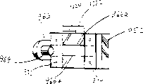
The miniscanning unit of size above for example being particularly suitable for having, is discussed in the device shown in Fig. 8.Point out that in above-mentioned module owing to be difficult to obtain mass balance, so pointing error occurs in such micromodule, this also can bring the problem of droop.This problem especially when hope obtains low frequency sweep discussed above.The present invention has overcome these difficulties by using shown specific mirror structure.Observe this structure in more detail, mirror 520 is installed on the public support that has permanent magnet 521.The mirror system that comprises mirror 520 and permanent magnet 521 rotates by pivot 522 with respect to the point of fixity on the base plate 501 523.Mirror system and pivot axis vertically extend from a side of pivot 522, and with respect on direction vis-a-vis, being provided with 520 and permanent magnet 521 Face to face with pivot 522 vertically extending nominal line.By producing the coil 524 of AC magnetic field,, drive mirror system and realize scanning motion in the mode that embodiment was discussed of reference Fig. 2 to Fig. 6.AC magnetic field is moved permanent magnet 521 to and fro, causes scanning motion.This structure and the contrast structure that Fig. 2 to Fig. 6 discussed be difference slightly, and its difference is that mirror 520 and permanent magnet 521 are positioned at the same side of driving axle 522, rather than is positioned at the opposite side that drives axle.
Consider the miniaturization of system, be difficult in mirror system, provide enough quality also and then by enough amounts to reduce vibration frequency to increase moment of inertia.Introducing quality can cause droop and add any other quality making this problem more serious.In the embodiment that Fig. 8 asked, overcome this point by the additional magnetic cell 530 that is positioned on the base plate 501 near the introducing permanent magnet 521.For example, unit 530 is the iron bars from base plate 501 projections.Because the mutual magnetic action between iron bar 530 and the permanent magnet 521, give permanent magnet 521 and mirror system entirely biasing it is aimed at iron bar.Thereby realized mirror system quality effective increase and reduced pointing error/droop thus.Certainly, can be appreciated that, can replace iron bar by any other suitable magnetic element 530.
According to a further aspect in the invention, provide a kind of scanner module system, be suitable for overcoming the difficulty relevant with the interference that causes by the surround lighting in the scanner environment.
This problem is especially conflicted with non-return polymerization (non-retro-reflective) bar code scanning system, and detecting device is not only collected the reading optical beam that is produced by scanner in this system, but also collects surround lighting.This will cause inferior performance, especially in the media of high ambient light environment.To know, and come filtering to address this problem by the caused noise of ambient light environment by being provided for catoptrical suitable light filter.The spatial filtering of noise depends on the scanning patter that is formed by the reflection light that bar code received.The waveform that is formed by the reflection light that bar code received is depended in the instantaneous filtering of noise.The normal light spectrum filter depends on following factors:
A) caused by the changeability of visible laser diode (VLD) processing
Wavelength variations;
B) by the aging wavelength variations that causes of VLD;
C) to a given VLD wavelength with variation of temperature;
D) light transmission and the relation that receives optic angle;
E) the multi-mode laser effect of VLD.
In order to regulate above-mentioned all factors, light filter has the bandwidth of about 70nm usually.This is the order of magnitude wideer than the spectral width of single VLD mould, and the result is, is keeping a large amount of unwanted noises that caused by the ambient light environment.In addition, under the situation that does not influence scanner performance, can not change the optical filtering parameter.
Referring to Fig. 9, show a kind of scheme that the present invention proposes.This device comprises a fixing light filter and the VLD with tunable wavelength, and tuning parameter is the temperature of VLD.
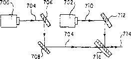
Generally represent a scan module with 540.To recognize, to reference to the single module of top embodiment discussion or in officely what can comprise the element of discussing below in its suitable form.Module 540 comprises the laser instrument 541 of an emission reading optical beam 542.Make light beam 542 change direction by reverberator 543 and be mapped on the scanning system 544, represent with the individual reflection device in the drawings, this reverberator is movably so that by make light beam 542 scannings along the direction to-and-fro movement shown in the arrow A.Resulting scanning light beam is used diagrammatic representation by main beam 555, and scanning limit(s) is by dotted line 556 and 556 ' expression.In order to use the wavelength that comes tuned laser 541 as the temperature of tuner parameters, laser instrument 541 is placed on the thermoelectric cooling/heating unit 560, this individual laser package is on a submounts or in chip that forms in any known manner.Refrigeration/heating unit 560 can be any known type, for example, can be the refrigeration/heating unit that flows through the amplitude and the type that direction changes temperature of its electric current by change.Thereby the wavelength of laser instrument 541 can remain in the free transmission range of the light filter that is used for the detecting device (not shown) and thereby can use narrower band logical.
Usually can control temperature in various manners according to feedback signal.For example, make reflector sections silver-plated, transmit the part of reading optical beam so that reflect the great majority of reading optical beam 542, shown in 561.Receive the light beam 561 of transmission by assisted detector 562.Assisted detector 562 can be located on the module 540 or be retained in the scanner shell, when suitable.Assisted detector 562 monitor reading optical beams 561 hop wavelength and control signal is provided for refrigeration/heating unit 560 so that obtain temperature desired the wavelength of reading optical beam 542 is remained in the logical scope of band of light filter.By control line 563 transmission of control signals.This shows that a method of control temperature is to make that assisted detector 562 is tuning to provide peak response with a desired wavelength in free transmission range.Control the temperature of refrigeration/heating unit 560, make the output maximum of assisted detector 562.
This scheme remains in the desirable frequency band wavelength of reading optical beam 562.The result is that along with critically controlling wave length shift, light filter has the bandwidth that significantly reduces.Therefore, the energy elimination is by the irrelevant noise of the caused major part of ambient light environment, thus signal to noise ratio (S/N ratio) that is improved and performance.
Embodiment shown in Figure 9 be particularly suitable for antagonism because above-mentioned factor a) to c), and the wavelength variations that occurs is promptly processed the wavelength change that changeability, aging and temperature occur when obvious.Be appreciated that the performance that therefore this embodiment will be improved.
Use embodiment shown in Figure 10 will further improve performance, this embodiment also considers because the caused wavelength variations of relation of the angle of light transmission and reception light.By being set again, assisted detector realizes this point with the downstream that is located at scanning system 544.Therefore can make the reverberator 543 that changes direction all silver-plated.And the silver-plated mirror 565 of another part is placed in the path by light beam scanning system 544 reflection, that cover whole sweep limit, so that be reflected and changed direction by catoptron 565 in the part by the light beam in the boundary of Reference numeral 556 and 556 ' expression.Detecting device 566 detects the part of the change direction of reading optical beam.Detecting device 566 detects the wavelength (using the detecting device 562 similar modes of being discussed with reference Fig. 9) of reading optical beams and prompting message about scan angle is provided.This information feedback is also controlled thus the temperature of refrigeration/heating unit 560 to controller 567 (can be any suitable processor).Certainly, be appreciated that controller 567 can be integrally formed with detecting device, perhaps can be formed for the part of the controller of module 542 on the whole.Thereby the wavelength that can control laser instrument 541 depends on the variation of the light transmission that receives the optic angle degree with correction.Should be appreciated that for this embodiment can be operated, must change the temperature of refrigeration/heating unit 560 and laser instrument with enough fast speed, to catch up with the variation of scan angle.Certainly, can realize this point, and be reduced as minimum by the thermal mass that makes whole refrigeration/heating unit 560 and laser instrument 541 systems and can regulate sweep speed faster for enough slow sweep speed.
By selecting with the lasing suitable VLD of single vertical mould, the system that can also improve further is with Consideration e) (some VLD is with several spectrum moulds generation laser) variation of causing.The various VLD that can satisfy this requirement are known, for example, and most of index guide structure VLD.Produce laser even be appreciated that VLD with several moulds, also can identify improvement, but they are not main key points.
Use another kind of method, introduce the VLD of fixed wave length and can use tunable filter to replace.In the case, can feed back light filter by the control signal of assisted detector 562 or composite wavelength and 566 receptions of scan angle detecting device, so that light filter is followed the wavelength variations of laser instrument 541.Tunable filter applicatory is known, for example, by the article of several pieces of relevant electric tunable spectral filters of the 6th phase of optical engineering (in November, 1981/Dec) the 805th to 845 page of collection, can know tunable light filter.Should be appreciated that system other features can with reference Fig. 9 and 10 described similar.
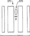
According to a further aspect in the invention, the one-dimensional bar code symbol of hope improvement difference quality reads.As everyone knows, have reading optical beam oval cross sections, that major axis is parallel with bar direction or septal direction by use and improve the precision of reading one-dimensional bar code, as shown in figure 11, show the luminous point of reading optical beam and this luminous point enlargedly by the scanning direction bar code symbol 571 shown in the arrow B with 570.It is oval-shaped reading luminous point, and its major axis is parallel with the direction of bar and vertical with the direction of scanning.The result is that the sign indicating number defective on the vertical direction is a mixing.
Hope can increase the working range of a given scanner, so that scanner can be more general.In order to increase the working range of scanner to high density bar code (3 to 10mil), can increase the far-end of working range by the focal aperture size that increases laser instrument in the direction of scanning, more the near-end of working range is reduced by making beam waist near the aperture.In Figure 12, show this point with figure.Laser instrument 575 is by the emission light beam 576 in the gathering aperture 577 of circle.Light beam 576 has a waist shown in amplifying with W.By increasing the aperture size on the direction of scanning (still representing with arrow B), working range increases, but beam waist reduces.Thereby, if near bad bar code of printing of laser beam waist scanning, then owing to the not too uniform result of the defective in the bar code on the direction of scanning, to increase the size of reading optical beam luminous point, thereby cause by the noise of the elongated oval point vertical in can not the elimination read output signal with sweep trace.Wish to eliminate or reduce the performance degradation that working range is had adverse effect.
The present invention has solved a difficult problem with known solutions, comes the improvement state by discerning changeable systematic parameter, and promptly laser instrument is assembled aperture shape.Particularly preferred shape is described below.If found to have optimized the shape of assembling the aperture, then can increase laser optical with a tight waist and under the situation of not losing the scanner working range bar code to the difference quality obtain improved signal to noise ratio (S/N ratio).
Conventional aperture shape generally be circle or rectangle be aperture size and beam waist position owing to can be used for increasing the parameter that only has of scanner working range; Press as mentioned above, this will make beam waist reduce and working range increases.Various other aperture shape are shown among Figure 13 a to 13c.Referring to Figure 13 a, show optimization aperture with stairstepping.This aperture can be formed by symmetrically arranged series of rectangular A1, A2, A3, A1 ', A2 ' A3 ' as shown in the figure.Each all (illustrates) side that different length is arranged again to rectangle A1, A1 ' etc. with arrow B in the direction of scanning, find the wideest rectangle in the centre, in the above and below find the narrowest rectangle.
In order to make the light scattering that manufacturing process is easy and minimizing is located in the sharp corner, the approaching smooth form of shape shown in selection and Figure 13 a.For example, shown in Figure 13 b, can use the diamond of fillet, or shown in Figure 13 c, use have that last boss rises and following boss rises, rise and following boss plays the circle of extension by last boss.
In fact, analyze the optimization aperture shape that can obtain shown in Figure 13 a by MTF, MTF is the convolution integer of aperture function.We forward the mathematics manipulation of using MTF to analyze now to.
Suppose that scanner wants to read 6,7.5,20 and 55 mil sign indicating numbers.Usually after optimizing the scanner working range, the MTF of the highest code density (being 6 mils in our example) changes the vs target range, and is described as the cross mark curve among Figure 14.Letting as assume that digital quantizer can provide at MTF>15% reads." (0.686mm) scanner of wide rectangular aperture for 6 mil bar codes, will provide from 2.5 " (63.5mm) to 9 " working range (228.6mm) in the example shown, to have 0.027.
For the sign indicating number of 6 mils, the MTF curve is in that " (130mm) the beam waist position reaches about 45% maximal value from scanner 5.Have than the much bigger maximal value MTF of threshold value 15% performance of scanner is not exerted an influence.Scanner has been eliminated the higher-spatial frequencies of expression printing defects, and noise increases the light beam around the beam waist position.Ideally, wish a just in time flat MTF curve on threshold value.In other words, beam waist increases till reaching flat MTF curve.
Therefore, use additional degree of freedom for the shape of controlling the MTF curve, that is, and the aperture shape when reading bar code.For shown in Figure 13 a, by three apertures that the rectangular area constitutes that have different sides along direction of scanning x1, x2 and x3, consider that MTF is the convolution integer of aperture function, the MTF in the aperture shown in calculating by following formula:
MIF=(MTF1.S1+MTF2.S2+MTF3+.S3+...)/(P1+P2+P3...)
Wherein, MTFI is the MTF in the i zone in aperture, the laser power of Pi in the i zone.Thereby we have the degree of freedom of additional design by making the aperture have certain shape.The example in aperture that flat MTF is provided for 6 mil sign indicating numbers is in Figure 13 a.The MTF that 7.5 mils, 20 mils and 55 mils are calculated is respectively represented by the solid line of Figure 15 to 17.People can reckon with, will eliminate size all printing defects littler than 6 mils.
The another kind of possibility of aperture shape optimization is to increase the working range of low-density bar code (40,55 mil) when keeping the wide region of high density bar code, as what seen from Figure 16 and 17.
Referring to Figure 14, provide by following formula for the nominal MTF curvilinear function of " diamond " aperture and 6 mil sign indicating numbers:
Wherein wb is a code density, and z is a distance (mm) of leaving the aperture, and x is the distance between laser instrument and the lens focal plane, and e is the angle of divergence of laser instrument, and Ax is the aperture size (inch) of aperture relevant portion.The numerical value that provides is corresponding with the embodiment of Figure 13 a.
Distance W R is a working range defined above, and shows aperture, right angle (curve of representing with cross) and optimize the MTF curve in aperture (solid line).The threshold value with dashed lines of MTF=15% draws, and limits working range WR.
Figure 15 to 17 uses identical convention, but respectively at the sign indicating number of 7.5 mils, 20 close, 55 mils.Represent the improvement of working range by ▲ WR.For Figure 17, selected 20% threshold value, as discussed above, can realize such low-density bar code.
According to a further aspect in the invention, the dead zone minimizing problem to little scan module has proposed suggestion.
With reference to Figure 19, show the conventional scheme that is used to improve small-sized non-return optically focused (non-retro-reflective) peacekeeping bidimensional scan module from above.Respective detection device (for example, photodiode) 602,603 in the scan module 605 of two lens 600,601 and any kind is corresponding, for example, and above with reference to the described module type of other embodiments of the invention.Other element of scan module 605 is not shown, for example, laser instrument, or the like.Lens are used to reduce the visual field and eliminate a part of ground unrest and ambient light thus.Lens 600,601 also amplify the signal collection zone of respective detection device 602,603, thereby have increased signal to noise ratio (S/N ratio).Adder (not shown) with general type will be from the signal plus of two detecting devices.Respectively by the place shown in the opposite hatched area 604 and 605 of separately direction, will see the Non-overlapping Domain that is called " dead band " that has to represent in the visual field of each detecting device by distance L d.When attempting to scan the mark that prints in this zone, will in this zone, obtain non-homogeneous signal.Especially, the center will or be zero or is the twice of the amplitude of its end with signal.The dead zone defines a non-area decoder, and the result is, near " noise " or near the output window of actual scanning module, can not realize decoding.Should be appreciated that, usually wish to realize such sign indicating number that touches, if but make photodiode oppositely move the zone of to lose the job for visual angle with covering " dead band ".Figure 20 and 21 shows the side view and the front view of the device of Figure 19 respectively.
There is shown the scheme of the present invention's suggestion on the plane of Figure 22.Except two detecting devices 602,603, be provided with one the 3rd photoelectric detector 606 at the center of module 605.The draw visual field of the 3rd detecting device 606 and represent the visual field of the 3rd detecting device of with dashed lines with Reference numeral 607.It will be appreciated that the 3rd detecting device 606 will detect the signal in the dead band, under the situation of the working range of not losing primary detector 602,603, provide additional working range.Because near the signal of scan module 605 is high-quality relatively and than much bigger away from the signal of scan module, so little photoelectric detector is just enough.Less photodiode detector needn't be decoded above the signal of distance L d because two bigger detecting devices sufficiently covered should the zone.Less detecting device 606 helps the decoding to the axis proximal marker especially.In order to make figure suitably big, use a suitable mirror system to make the laser path bending.This means that two primary detectors 602,603 have to remove farther, and the 3rd detecting device has relaxed this situation once more by covering the dead band.Figure 23 and 24 shows respectively according to the side view of device of the present invention and front view.
According to a further aspect in the invention, wish to obtain to have minimal modification or do not revise the multidigit performance (multi-bit performance) that has element now.Various non-multidigit scan modules are well-known.For example, introduce this feature, specifically comprise a sweep signal input, sweep signal digital quantizer and digitized signal output with top scan module or scanning machine referring to figs. 1 through 7 types of discussing, and simulating signal differentiator and output.The front considered that the multidigit structure of introducing such element was infeasible, unless introduce special IC (ASIC), because do not increase the space of multidigit circuit on the little circuit board in the conventional sweep module.In addition, even can realize the multidigit scan module, still, the multidigit scan module also can be incompatible with the demoder in all existing portable terminal device.
The present invention utilizes existing element in such module and multidigit demoder to carry out interface to solve these problems by keeping present scan module in improved mode.
Figure 25 illustrates an example of the present invention.Represent a scan module (although can use any appropriate module) with 620 with reference to figure 2 described types.Only show those elements relevant with signal Processing.Module 620 comprises 621 and digital quantizers 622 that analog input signal converted to numeral output 623 of a signal input.Numeral output remains in the interface leading-out end 624.This permission is used scan module with the actual module form of being arranged to be connected with suitable decoder module.Except that digital converter 622, also has a simulating signal differentiator 620.In the second interface leading-out end 627, keep output differential signal 626.Conventional non-multidigit system does not use the second interface leading-out end.
Referring to Figure 26, show a decoder module.For non-multidigit decoding, digitized signal 623 is received by interface leading-out end 624 and is decoded in demoder 631.Do not use differential signal 626 interface leading-out ends 627; The standard digital converter bar figure signal that is provided by the digital quantizer on the scanning board 620 622 is provided demoder.
Can realize the multidigit performance with a use differentiator signal 626 with from the suitable demoder of digitized figure signal of digital quantizer 622.Comprise analog to digital converter 632 as the part of decoder module 630.When demoder 631 detected the conversion of exporting from the digital quantizer of scanning machine, it passed the signal to controller 634 by line 633, made analog to digital converter 632 sampling differential signals.Thereby analog to digital converter 632 provides edge strength information for demoder 631 by line 635.Scan module digital quantizer 622 is supplied with marginal position and polarity information.The cardinal principle that multibit signal is handled is well-known in prior art, just at length this is not studied at this, still should be understood that to monitor the parameter of being concerned about.
Analog to digital converter 632 can be an independent integrated circuit on the decoding deck (as shown in figure 26), or analog to digital converter 632 is included in the decoding microprocessor chip itself.A suitable microprocessor is produced by Toshiba.
In the delegation of input signal 621, have under the situation at two plus or minus edges, conventional digital quantizer is very sensitive, even so that for the very little negative peak between two positive peaks or vice versa, digital quantizer 622 also will detect all edges and these feeble signals in the usual way the working strength data can not obtain.Have been found that this is not the main cause that causes signal Processing to be degenerated.
Figure 18 has schematically illustrated the annexation between scan module 620 and decoder module 630.
To see, and improved multidigit modular unit and the structure of being discussed with reference to figure 1-7 or 28-31 can be combined, and, make the range of application of basic back reflection scan module described here wideer with the interchangeability and the module voltinism of further this device of improvement.
According to a further aspect in the invention, wish to introduce two or more laser instruments, particularly use more and more littler duodiode characteristic scanner, with the consideration of the ergonomical of satisfying desired size/relate to.
According to an embodiment shown in Figure 27 of the present invention, duodiode (ER) device comprises that one is used for first laser instrument that long range sweep focuses on and one and is used for the second scanning focused laser instrument of low coverage.In order to obtain desired small size, long distance laser instrument 700 is placed on the back of low coverage laser instrument 702 with back-to-back structure.Make long distance laser beam 704 near low coverage laser instrument 702, change direction by mirror 706 and 708.Change the direction of low coverage laser beam 710 by mirror 712.According to an embodiment, make two light beam recombinants at 714 places by " specialized mirror " 716.Make the specialized mirror part silver-plated or crack, so that reflection low coverage light and transmit the long distance light beam.In addition, specialized mirror 716 can be offset long distance beam path 704 so that long distance light beam 704 passes through specialized mirror 716.
Except energy is reduced in size, will find, use when having module now and can introduce this device, only be included in the add ons in the free space.Using the place of the modular unit of type being discussed, will find that can easily embody the ability that increases additional laser and element, the adaptability that makes existing element is with applicability is bigger again at this.One imagines surely, and the device of Figure 27 can combine with the modular device that earlier in respect of figures 1-6 and 28-31 are discussed.
Should be appreciated that, each feature described above, or two or more combination can both be applied in the scanner of other class different with top discussion type and bar-code reader.
Although the back reflection scan module of electricity consumption optical reader has been described the present invention as an example,, do not want to limit the present invention on the illustrated details, because under the situation that does not break away from spirit of the present invention, can make various modifications and structural change.
Under situation about further not analyzing, foregoing just discloses main points of the present invention so fully, thereby by using general knowledge, others can easily make it be applicable to the various application of not saving feature from prior art or viewpoint, clearly constitute the essential feature of general or particular aspects of the present invention, therefore such modification should and be wished to be included in the implication and scope of equivalent of following claim.Stated in the appended claims and thought content new and that hope is protected by letters patent.
Claims (57)
1, a kind of scanning element that is used to make the beam flying bar code, described scanning element comprises:
A) support;
B) sheet type elastomeric element, it is connected described support one end;
C) actuating arm, it links to each other with second end of described elastomeric element, and extends along a side of described elastomeric element;
D) reflector element, it is connected to described actuating arm;
E) magnet, it is connected to described actuating arm; And
F) driver, be used for masterpiece is used in described magnet, and described reflector element and described magnet are moved at least along a circumferencial direction, wherein, described driver comprises a solenoid, this solenoid has the hole by its center, and during described magnet movement, described coil is accepted the described magnet by coil hole at least in part; And
G) refrative mirror, it is along the beam path setting from described light source to described scanning element, and be characterised in that: described refrative mirror is positioned at the back of converging optical element.
2, scanning element as claimed in claim 1, wherein, described magnet and described reflector element are positioned at the different ends of described actuating arm.
3, scanning element as claimed in claim 2, wherein, described actuating arm, described reflector element and described magnet form a balanced structure.
4, scanning element as claimed in claim 1, wherein, described reflector element is a level crossing.
5, scanning element as claimed in claim 4, wherein, described level crossing is a kind of plastic surface mirror.
6, scanning element as claimed in claim 1, wherein, described actuating arm is a plastics actuating arm.
7, scanning element as claimed in claim 1, wherein, described actuating arm and described reflector element constitute a single molded plastics unit.
8, scanning element as claimed in claim 1, wherein, described type elastomeric element made by mylar.
9, scanning element as claimed in claim 1, wherein, described type elastomeric element comprises at least two sheet springs.
10, scanning element as claimed in claim 1, wherein, described source is a laser diode, and described light beam is a laser beam.
11, a kind of by utilizing the beam flying symbol and collecting the scan module that the reflected light that returns from symbol is read bar code symbol, described scan module comprises:
A) base plate;
B) light source is used to produce described light beam;
C) scanning element is used to make the light beam that is produced to change direction and utilize the described light beam that has changed direction to scan described symbol in the mobile mode of vibrating, and described scanning element comprises:
I) support, it is connected on the described base plate;
Ii) sheet type elastomeric element, it is connected described support one end;
Iii) actuating arm, it links to each other with second end of described elastomeric element, and extends along a side of described elastomeric element;
Iv) scanning mirror, it is connected to described actuating arm;
V) magnet, it is connected to described actuating arm; And
Vi) driver is used for masterpiece is used in described magnet, and described scanning mirror and described magnet are moved along a circumferencial direction at least;
D) converging optical element is used to collect the reflected light that returns from described symbol;
E) detecting device is used to detect the reflected light of described collection, and converts the reflected light of described detection to an electric signal;
F) treatment circuit is used to handle described electric signal; And
G) refrative mirror, it is along the beam path setting from described light source to described scanning element, and be characterised in that: described refrative mirror is positioned at the back of described converging optical element.
12, scan module as claimed in claim 11, wherein, the light beam bending that described refrative mirror produces described light source, and change described beam direction and the described scanning mirror of directive.
13, scan module as claimed in claim 12, wherein, described refrative mirror has a curvature, is used to revise the xsect characteristic of described light beam.
14, scan module as claimed in claim 11, wherein, described driver comprises a solenoid, this solenoid heart therein has the hole.
15, scan module as claimed in claim 14, wherein, during described magnet oscillating movement, described coil is accepted the described magnet by coil hole at least in part.
16, scan module as claimed in claim 11, wherein, described magnet and described scanning mirror are positioned at the different ends of described actuating arm.
17, scan module as claimed in claim 16, wherein, described actuating arm, described scanning mirror and described magnet form a balanced structure.
18, scan module as claimed in claim 11, wherein, described scanning mirror is a kind of plastic lens.
19, scan module as claimed in claim 12, wherein, described converging optical element comprises a condenser with through hole, and wherein, the light beam bending that described refrative mirror produces described light source, and make the beam direction in the hole by described condenser change into the described scanning mirror of directive.
20, scan module as claimed in claim 11, wherein, described actuating arm is a plastics actuating arm.
21, scan module as claimed in claim 11, wherein, described actuating arm and described reflector element constitute a single molded plastics unit.
22, scan module as claimed in claim 11, wherein, described type elastomeric element made by mylar.
23, scan module as claimed in claim 11, wherein, described type elastomeric element comprises at least two sheet springs.
24, scan module as claimed in claim 11, wherein, described source is a laser diode, and described light beam is a laser beam.
25, scan module as claimed in claim 14 further comprises a first circuit board, is used for providing electrical connection to described light source, described detecting device and described coil.
26, scan module as claimed in claim 11, wherein, described treatment circuit comprises Analogue ASIC's.
27, scan module as claimed in claim 11, wherein, described treatment circuit comprises the chip board circuit.
28, scan module as claimed in claim 11, wherein, described treatment circuit includes the programmable feature of at least one operating parameter of selectively revising described scan module.
29, scan module as claimed in claim 11 wherein, is stored in described operating parameter in the described treatment circuit.
30, scan module as claimed in claim 11 further comprises a scanning element centering feature, is used to adjust the position of described scanning element with respect to base plate.
31, scan module as claimed in claim 11, wherein, base plate comprises at least two aligned units, is used for described scan module is positioned properly the housing of data collector.
32, scan module as claimed in claim 11, wherein, described at least two aligned units comprise the aligning trimmer.
33, scan module as claimed in claim 31, wherein, described at least two aligned units comprise mating holes.
34, scan module as claimed in claim 19, wherein, the width of described condenser equates with the minimum projection width of described scanning mirror basically.
35, scan module as claimed in claim 11, wherein, the transmission/scanning of described laser beam is carried out with catoptrical being collected in the different planes.
36, a kind of by utilizing the laser beam flying symbol and collecting the scan module that the reflected light that returns from symbol is read bar code, described scan module comprises:
A) metal base plate;
B) condenser is used to collect the reflected light that returns from described symbol, and described condenser has the hole of perforation;
C) lasing light emitter is used to produce laser beam;
D) refrative mirror is used to make the described laser beam bending of described lasing light emitter generation, and throws the laser beam of described bending by the hole in the described condenser;
E) scanning element is used for accepting hole by described condenser and projects laser on it, and utilizes described laser beam flying symbol in the vibratory movement mode, and described scanning element comprises:
I) support, it is connected on the described metal base plate;
Ii) sheet type elastomeric element, it is connected described support one end;
Iii) actuating arm, it links to each other with second end of described elastomeric element, and extends along a side of described elastomeric element;
Iv) scanning mirror, first end that it has a width and is connected to described actuating arm is used for accepting the crooked laser beam from the hole projection of described condenser, and makes the described symbol of laser beam directive;
V) magnet, it is connected to second end of described actuating arm; And
Vi) solenoid is used for masterpiece is used in described magnet, and described scanning mirror and described magnet are moved at least one circumferencial direction;
F) detecting device is used to detect the reflected light of described collection, and converts the reflected light of described detection to an electric signal; And
G) first circuit board, it connects described lasing light emitter, described detecting device and described coil; And
H) second circuit board, it comprises the treatment circuit of handling described electric signal.
37, scan module as claimed in claim 36, wherein, described refrative mirror has a curvature, is used to revise the xsect characteristic of described laser beam.
38, scan module as claimed in claim 37, wherein, described refrative mirror has a cylindrical curvature.
39, scan module as claimed in claim 36, wherein, described coil is accepted the described magnet by described coil hole at least in part.
40, scan module as claimed in claim 36, wherein, described actuating arm and described scanning mirror constitute single molded plastic parts.
41, scan module as claimed in claim 36, wherein, described actuating arm, described scanning mirror and described magnet form a balanced structure.
42, scan module as claimed in claim 36, wherein, described type elastomeric element made by mylar.
43, scan module as claimed in claim 36, wherein, described type elastomeric element comprises at least two sheet springs.
44, scan module as claimed in claim 36, wherein, described treatment circuit comprises an application specific integrated circuit.
45, scan module as claimed in claim 36, wherein, described treatment circuit comprises a chip board circuit.
46, scan module as claimed in claim 36, wherein, described treatment circuit includes the programmable feature of at least one operating parameter of selectively revising described scan module.
47, scan module as claimed in claim 46 wherein, is stored in described operating parameter in the described treatment circuit.
48, scan module as claimed in claim 46, wherein, described treatment circuit further comprises a demoder, is used for the scanning bar code coded message is decoded.
49, scan module as claimed in claim 36 further comprises a scanning element centering feature, is used to adjust the position of described scanning element with respect to described base plate.
50, scan module as claimed in claim 36, wherein, the width of described condenser equates with the minimum projection width of described scanning mirror basically.
51, scan module as claimed in claim 36, wherein, the volume of described scan module is less than 0.15 cubic inch.
52, scan module as claimed in claim 51 has about 0.8 inch length, about 0.5 inch width and about 0.3 inch height.
53, scan module as claimed in claim 36, wherein, base plate comprises at least two aligned units, is used for described scan module is positioned properly the housing of data collector.
54, scan module as claimed in claim 53, wherein, described at least two aligned units comprise the aligning trimmer.
55, scan module as claimed in claim 53, wherein, described at least two aligned units comprise mating holes.
56, scan module as claimed in claim 36, wherein, described coil comprises at least two windings, first around level be the excitation winding, and second winding for the feedback winding.
57, scan module as claimed in claim 36, wherein, the transmission/scanning of described laser beam is carried out with catoptrical being collected in the different planes.
Applications Claiming Priority (2)
| Application Number | Priority Date | Filing Date | Title |
|---|---|---|---|
| US09/275,858 | 1999-03-24 | ||
| US09/275,858 US6360949B1 (en) | 1995-10-10 | 1999-03-24 | Retro-reflective scan module for electro-optical readers |
Publications (2)
| Publication Number | Publication Date |
|---|---|
| CN1278088A CN1278088A (en) | 2000-12-27 |
| CN1237472C true CN1237472C (en) | 2006-01-18 |
Family
ID=23054112
Family Applications (1)
| Application Number | Title | Priority Date | Filing Date |
|---|---|---|---|
| CNB001054104A Expired - Fee Related CN1237472C (en) | 1999-03-24 | 2000-03-24 | Inverse reflextion scanning module used for electrooptical sensing device |
Country Status (5)
| Country | Link |
|---|---|
| US (1) | US6360949B1 (en) |
| EP (1) | EP1039409A3 (en) |
| JP (1) | JP2000298242A (en) |
| CN (1) | CN1237472C (en) |
| TW (1) | TW498287B (en) |
Families Citing this family (90)
| Publication number | Priority date | Publication date | Assignee | Title |
|---|---|---|---|---|
| US6631842B1 (en) * | 2000-06-07 | 2003-10-14 | Metrologic Instruments, Inc. | Method of and system for producing images of objects using planar laser illumination beams and image detection arrays |
| US8352400B2 (en) | 1991-12-23 | 2013-01-08 | Hoffberg Steven M | Adaptive pattern recognition based controller apparatus and method and human-factored interface therefore |
| US7028899B2 (en) * | 1999-06-07 | 2006-04-18 | Metrologic Instruments, Inc. | Method of speckle-noise pattern reduction and apparatus therefore based on reducing the temporal-coherence of the planar laser illumination beam before it illuminates the target object by applying temporal phase modulation techniques during the transmission of the plib towards the target |
| US7966078B2 (en) | 1999-02-01 | 2011-06-21 | Steven Hoffberg | Network media appliance system and method |
| US6578767B1 (en) * | 1999-07-16 | 2003-06-17 | Symbol Technologies, Inc. | Low cost bar code reader |
| US7270274B2 (en) | 1999-10-04 | 2007-09-18 | Hand Held Products, Inc. | Imaging module comprising support post for optical reader |
| WO2001026036A2 (en) * | 1999-10-04 | 2001-04-12 | Welch Allyn Data Collection, Inc. | Imaging module for optical reader |
| US6932271B2 (en) * | 2000-01-27 | 2005-08-23 | Ricoh Company, Ltd. | Optical scan module, optical scanner, optical scan method, image generator and image reader |
| EP2093694B1 (en) * | 2000-10-26 | 2011-06-22 | Datalogic S.p.A. | Receiving chamber for a laser reader |
| US20020050519A1 (en) * | 2000-10-26 | 2002-05-02 | Oliva Guido M. | Laser module for reading optical codes |
| US20030098352A1 (en) * | 2000-11-24 | 2003-05-29 | Metrologic Instruments, Inc. | Handheld imaging device employing planar light illumination and linear imaging with image-based velocity detection and aspect ratio compensation |
| US7164810B2 (en) * | 2001-11-21 | 2007-01-16 | Metrologic Instruments, Inc. | Planar light illumination and linear imaging (PLILIM) device with image-based velocity detection and aspect ratio compensation |
| US6523751B2 (en) * | 2000-12-15 | 2003-02-25 | Yu-Chun Chang | Scanning apparatus |
| US6761316B2 (en) | 2001-03-27 | 2004-07-13 | Symbol Technologies, Inc. | Compact auto ID reader and radio frequency transceiver data collection module |
| DE60238341D1 (en) | 2001-08-31 | 2010-12-30 | Optoelectronics Co Ltd | MODULE FOR AN OPTICAL INFORMATION READER |
| US6578765B2 (en) * | 2001-09-12 | 2003-06-17 | Psc Scanning, Inc. | Optical scanning system and integrated optics module therefor |
| US6811085B2 (en) * | 2001-10-26 | 2004-11-02 | Symbol Technologies, Inc. | Miniature imager |
| US6805295B2 (en) * | 2001-11-06 | 2004-10-19 | Symbol Technologies, Ltd. | High speed laser scan module with folded beam path |
| US7055747B2 (en) * | 2002-06-11 | 2006-06-06 | Hand Held Products, Inc. | Long range optical reader |
| TWI261207B (en) * | 2002-04-18 | 2006-09-01 | Symbol Technologies Inc | Scan module for a system for electro-optically reading indicia |
| JP4364482B2 (en) | 2002-04-23 | 2009-11-18 | 株式会社キーエンス | Optical unit for optical symbol reader |
| CN1318879C (en) * | 2002-05-14 | 2007-05-30 | 奥林巴斯株式会社 | Barcode reader |
| US20030222147A1 (en) * | 2002-06-04 | 2003-12-04 | Hand Held Products, Inc. | Optical reader having a plurality of imaging modules |
| US8596542B2 (en) | 2002-06-04 | 2013-12-03 | Hand Held Products, Inc. | Apparatus operative for capture of image data |
| US6802451B2 (en) * | 2002-08-07 | 2004-10-12 | Symbol Technologies, Inc. | Scanning actuator assembly for image projection modules, especially in portable instruments |
| US6899271B2 (en) * | 2003-05-05 | 2005-05-31 | Symbol Technologies, Inc. | Arrangement for and method of collecting and displaying information in real time along a line of sight |
| US6932274B2 (en) * | 2003-05-27 | 2005-08-23 | Symbol Technologies, Inc. | Vibration reduction in electro-optical readers |
| US7707039B2 (en) | 2004-02-15 | 2010-04-27 | Exbiblio B.V. | Automatic modification of web pages |
| US8442331B2 (en) | 2004-02-15 | 2013-05-14 | Google Inc. | Capturing text from rendered documents using supplemental information |
| US8521772B2 (en) | 2004-02-15 | 2013-08-27 | Google Inc. | Document enhancement system and method |
| US20060041484A1 (en) | 2004-04-01 | 2006-02-23 | King Martin T | Methods and systems for initiating application processes by data capture from rendered documents |
| US8799303B2 (en) | 2004-02-15 | 2014-08-05 | Google Inc. | Establishing an interactive environment for rendered documents |
| US7812860B2 (en) * | 2004-04-01 | 2010-10-12 | Exbiblio B.V. | Handheld device for capturing text from both a document printed on paper and a document displayed on a dynamic display device |
| US10635723B2 (en) | 2004-02-15 | 2020-04-28 | Google Llc | Search engines and systems with handheld document data capture devices |
| US7894670B2 (en) | 2004-04-01 | 2011-02-22 | Exbiblio B.V. | Triggering actions in response to optically or acoustically capturing keywords from a rendered document |
| US9116890B2 (en) | 2004-04-01 | 2015-08-25 | Google Inc. | Triggering actions in response to optically or acoustically capturing keywords from a rendered document |
| US9143638B2 (en) | 2004-04-01 | 2015-09-22 | Google Inc. | Data capture from rendered documents using handheld device |
| US20070300142A1 (en) | 2005-04-01 | 2007-12-27 | King Martin T | Contextual dynamic advertising based upon captured rendered text |
| US8793162B2 (en) | 2004-04-01 | 2014-07-29 | Google Inc. | Adding information or functionality to a rendered document via association with an electronic counterpart |
| US20080313172A1 (en) | 2004-12-03 | 2008-12-18 | King Martin T | Determining actions involving captured information and electronic content associated with rendered documents |
| US7990556B2 (en) | 2004-12-03 | 2011-08-02 | Google Inc. | Association of a portable scanner with input/output and storage devices |
| US8621349B2 (en) | 2004-04-01 | 2013-12-31 | Google Inc. | Publishing techniques for adding value to a rendered document |
| US8146156B2 (en) | 2004-04-01 | 2012-03-27 | Google Inc. | Archive of text captures from rendered documents |
| US20100185538A1 (en) * | 2004-04-01 | 2010-07-22 | Exbiblio B.V. | Content access with handheld document data capture devices |
| US9008447B2 (en) | 2004-04-01 | 2015-04-14 | Google Inc. | Method and system for character recognition |
| US8713418B2 (en) | 2004-04-12 | 2014-04-29 | Google Inc. | Adding value to a rendered document |
| US8489624B2 (en) | 2004-05-17 | 2013-07-16 | Google, Inc. | Processing techniques for text capture from a rendered document |
| US9460346B2 (en) | 2004-04-19 | 2016-10-04 | Google Inc. | Handheld device for capturing text from both a document printed on paper and a document displayed on a dynamic display device |
| US8620083B2 (en) | 2004-12-03 | 2013-12-31 | Google Inc. | Method and system for character recognition |
| US8874504B2 (en) | 2004-12-03 | 2014-10-28 | Google Inc. | Processing techniques for visual capture data from a rendered document |
| US8316068B2 (en) | 2004-06-04 | 2012-11-20 | Telefonaktiebolaget Lm Ericsson (Publ) | Memory compression |
| US8346620B2 (en) | 2004-07-19 | 2013-01-01 | Google Inc. | Automatic modification of web pages |
| US20110029504A1 (en) * | 2004-12-03 | 2011-02-03 | King Martin T | Searching and accessing documents on private networks for use with captures from rendered documents |
| GB0426662D0 (en) * | 2004-12-06 | 2005-01-05 | Univ St Andrews | Gas imager |
| US7207489B2 (en) * | 2005-01-31 | 2007-04-24 | Symbol Technologies, Inc. | Scan motor |
| US7281658B2 (en) * | 2005-01-31 | 2007-10-16 | Symbol Technologies, Inc. | Scan module |
| US7204424B2 (en) * | 2005-05-31 | 2007-04-17 | Symbol Technologies, Inc. | Retro-reflective scanner having exit window with positive optical power |
| US8002183B2 (en) * | 2005-10-20 | 2011-08-23 | Metrologic Instruments, Inc. | Scanner flipper integrity indicator |
| JP5493240B2 (en) * | 2005-11-21 | 2014-05-14 | 株式会社リコー | Optical scanning apparatus and image forming apparatus |
| US7273178B2 (en) * | 2006-01-20 | 2007-09-25 | Optoelectronics Co., Ltd. | Compact scan engine disposed within a scanner housing |
| US20110096174A1 (en) * | 2006-02-28 | 2011-04-28 | King Martin T | Accessing resources based on capturing information from a rendered document |
| EP2067119A2 (en) * | 2006-09-08 | 2009-06-10 | Exbiblio B.V. | Optical scanners, such as hand-held optical scanners |
| US7857223B2 (en) * | 2007-04-26 | 2010-12-28 | Microvision, Inc. | Scanning module for a scanner system having a MEMS device or the like |
| US7832641B2 (en) * | 2007-05-24 | 2010-11-16 | Metrologic Instruments, Inc. | Scanner switched to active state by sensed movement in quiescent scanning mechanism |
| US7992786B2 (en) * | 2007-08-22 | 2011-08-09 | Olympus Corporation | Bar code reader |
| US20100051696A1 (en) * | 2008-08-27 | 2010-03-04 | Symbol Technologies, Inc. | Illumination system for a bar code reader |
| DE202010018601U1 (en) | 2009-02-18 | 2018-04-30 | Google LLC (n.d.Ges.d. Staates Delaware) | Automatically collecting information, such as gathering information using a document recognizing device |
| US8447066B2 (en) * | 2009-03-12 | 2013-05-21 | Google Inc. | Performing actions based on capturing information from rendered documents, such as documents under copyright |
| WO2010105245A2 (en) | 2009-03-12 | 2010-09-16 | Exbiblio B.V. | Automatically providing content associated with captured information, such as information captured in real-time |
| US8059324B2 (en) * | 2009-09-23 | 2011-11-15 | Metrologic Instruments, Inc. | Scan element for use in scanning light and method of making the same |
| US8294969B2 (en) | 2009-09-23 | 2012-10-23 | Metrologic Instruments, Inc. | Scan element for use in scanning light and method of making the same |
| US8390909B2 (en) | 2009-09-23 | 2013-03-05 | Metrologic Instruments, Inc. | Molded elastomeric flexural elements for use in a laser scanning assemblies and scanners, and methods of manufacturing, tuning and adjusting the same |
| US9081799B2 (en) | 2009-12-04 | 2015-07-14 | Google Inc. | Using gestalt information to identify locations in printed information |
| US9323784B2 (en) | 2009-12-09 | 2016-04-26 | Google Inc. | Image search using text-based elements within the contents of images |
| US8561903B2 (en) | 2011-01-31 | 2013-10-22 | Hand Held Products, Inc. | System operative to adaptively select an image sensor for decodable indicia reading |
| US8608071B2 (en) | 2011-10-17 | 2013-12-17 | Honeywell Scanning And Mobility | Optical indicia reading terminal with two image sensors |
| US8915439B2 (en) | 2012-02-06 | 2014-12-23 | Metrologic Instruments, Inc. | Laser scanning modules embodying silicone scan element with torsional hinges |
| US8991707B2 (en) | 2012-05-21 | 2015-03-31 | Symbol Technologies, Inc. | Optical slot scanner having coaxial illuminaton |
| US8746563B2 (en) | 2012-06-10 | 2014-06-10 | Metrologic Instruments, Inc. | Laser scanning module with rotatably adjustable laser scanning assembly |
| CN103150538B (en) * | 2013-03-08 | 2015-10-28 | 公安部交通管理科学研究所 | Number plate reflective membrane two-dimensional bar code recognizing apparatus and reading method |
| US9016578B2 (en) | 2013-05-14 | 2015-04-28 | Symbol Technologies, Inc. | Apparatus for and method of electro-optically reading a target in the presence of ambient light by suppressing the ambient light |
| US8967478B2 (en) | 2013-05-16 | 2015-03-03 | Symbol Technologies, Inc. | Apparatus for and method of electro-optically reading a target in the presence of ambient light by rejecting the ambient light |
| US8925814B1 (en) | 2013-10-09 | 2015-01-06 | Symbol Technologies, Inc. | Apparatus for and method of monitoring output power of a laser beam during reading of targets |
| JP2015187853A (en) * | 2014-03-14 | 2015-10-29 | 株式会社リコー | Method for reading optical information code |
| FR3025913B1 (en) * | 2014-09-12 | 2016-09-09 | Biomerieux Sa | BAR CODE READING DEVICE AND MACHINE FOR AUTOMATED ANALYSIS OF A SAMPLE COMPRISING SUCH A DEVICE |
| CN105973150A (en) * | 2016-07-22 | 2016-09-28 | 武汉海达数云技术有限公司 | Three-dimensional laser scanner with inclined window mirror |
| JP6104436B1 (en) * | 2016-07-28 | 2017-03-29 | 株式会社オプトエレクトロニクス | Optical scanning module |
| CN110505814A (en) | 2017-02-20 | 2019-11-26 | 3M创新有限公司 | Optical goods and the system interacted |
| US11161668B1 (en) | 2020-07-22 | 2021-11-02 | Terry Hermanson | Packing material and method of manufacturing the packing material |
| CN112711959B (en) * | 2021-01-15 | 2024-02-02 | 苏州浩创信息科技有限公司 | Packaging structure, scanner and wearable intelligent device |
Family Cites Families (18)
| Publication number | Priority date | Publication date | Assignee | Title |
|---|---|---|---|---|
| US4983818A (en) * | 1989-01-30 | 1991-01-08 | Metrologic Instruments, Inc. | Data acquisition system with laser scanner module |
| US5367151A (en) | 1989-10-30 | 1994-11-22 | Symbol Technologies, Inc. | Slim scan module with interchangeable scan element |
| US5280165A (en) | 1989-10-30 | 1994-01-18 | Symbol Technolgoies, Inc. | Scan pattern generators for bar code symbol readers |
| US5479000A (en) | 1989-10-30 | 1995-12-26 | Symbol Technologies, Inc. | Compact scanning module for reading bar codes |
| US5552592A (en) * | 1989-10-30 | 1996-09-03 | Symbol Technologies, Inc. | Slim scan module with dual detectors |
| US5168149A (en) * | 1989-10-30 | 1992-12-01 | Symbol Technologies, Inc. | Scan pattern generators for bar code symbol readers |
| US5621371A (en) * | 1989-10-30 | 1997-04-15 | Symbol Technologies, Inc. | Arrangement for two-dimensional optical scanning with springs of different moduli of elasticity |
| US5581067A (en) | 1990-05-08 | 1996-12-03 | Symbol Technologies, Inc. | Compact bar code scanning module with shock protection |
| US5200597A (en) * | 1991-02-07 | 1993-04-06 | Psc, Inc. | Digitally controlled system for scanning and reading bar codes |
| US5329103A (en) * | 1991-10-30 | 1994-07-12 | Spectra-Physics | Laser beam scanner with low cost ditherer mechanism |
| US5214270A (en) * | 1991-11-22 | 1993-05-25 | Spectra-Physics | Modular handheld or fixed scanner |
| US6000619A (en) * | 1992-02-21 | 1999-12-14 | Spectra-Physics Scanning Systems, Inc. | Scanner assembly |
| US5629510A (en) | 1992-12-04 | 1997-05-13 | Psc Inc. | Bar code scanning and reading apparatus with an oscillating scanning engine |
| EP0660255A3 (en) * | 1993-12-24 | 1998-04-08 | Opticon Sensors Europe B.V. | Oscillation bar code reader |
| DE29623079U1 (en) * | 1995-10-10 | 1997-12-18 | Symbol Technologies Inc | Retroreflective scanning module for electro-optical readers |
| JPH09243942A (en) * | 1996-03-04 | 1997-09-19 | Brother Ind Ltd | Optical scanner |
| US6152372A (en) | 1996-09-23 | 2000-11-28 | Psc Scanning, Inc. | Dithering assemblies for barcode scanners |
| JPH1153462A (en) * | 1997-08-07 | 1999-02-26 | Hitachi Ltd | Laser system bar code scanner |
-
1999
- 1999-03-24 US US09/275,858 patent/US6360949B1/en not_active Expired - Fee Related
-
2000
- 2000-03-24 CN CNB001054104A patent/CN1237472C/en not_active Expired - Fee Related
- 2000-03-24 EP EP00106449A patent/EP1039409A3/en not_active Withdrawn
- 2000-03-24 JP JP2000085220A patent/JP2000298242A/en active Pending
- 2000-11-08 TW TW089105495A patent/TW498287B/en not_active IP Right Cessation
Also Published As
| Publication number | Publication date |
|---|---|
| CN1278088A (en) | 2000-12-27 |
| JP2000298242A (en) | 2000-10-24 |
| US6360949B1 (en) | 2002-03-26 |
| TW498287B (en) | 2002-08-11 |
| EP1039409A2 (en) | 2000-09-27 |
| EP1039409A3 (en) | 2002-05-15 |
Similar Documents
| Publication | Publication Date | Title |
|---|---|---|
| CN1237472C (en) | Inverse reflextion scanning module used for electrooptical sensing device | |
| CN1112649C (en) | Slim scan module with interchangeable X-Y scan element | |
| CN1156788C (en) | One piece optical assembly for low cost optical scanner | |
| CN1174336C (en) | Optic path design for scanning component of small bar code reader | |
| US5552592A (en) | Slim scan module with dual detectors | |
| JP2732459B2 (en) | Scan module for barcode reader | |
| KR100277272B1 (en) | Optical scanner with extended focal depth and scanning with extended focal depth | |
| CN1038537C (en) | Pre-objective scanner with flexible optical support | |
| US7992786B2 (en) | Bar code reader | |
| JP3089147U (en) | Scanning module for reading display symbols electro-optically | |
| US20040031848A1 (en) | Positioning of photodetectors in optical scanning modules for use in bar code readers for reducing specular reflection | |
| CN1242354C (en) | Small scanning module with magnetic centring scanning mirror | |
| US6805295B2 (en) | High speed laser scan module with folded beam path | |
| US7514702B2 (en) | Compact scan engine | |
| JP4435469B2 (en) | High speed laser scanning module with reflected beam path | |
| US6225641B1 (en) | Optical reader for scanning optical indicia by movement of an aperture relative to an image plane | |
| US6702184B2 (en) | Collection optics for low profile single line scanning assembly in compact bar code readers | |
| EP0768614A2 (en) | Retroreflective scan module for electro-optical readers | |
| CN1038536C (en) | Light scanor with enlarged focal length | |
| CN1038279C (en) | Piezo-beam-deflector of bar code reading apparatus | |
| CN1034778C (en) | High speed scanner with unit of high frequency and low stress | |
| CN1078566A (en) | Mirrorless scanners with movable laser, optical and sensor components |
Legal Events
| Date | Code | Title | Description |
|---|---|---|---|
| C06 | Publication | ||
| PB01 | Publication | ||
| C10 | Entry into substantive examination | ||
| SE01 | Entry into force of request for substantive examination | ||
| C14 | Grant of patent or utility model | ||
| GR01 | Patent grant | ||
| C17 | Cessation of patent right | ||
| CF01 | Termination of patent right due to non-payment of annual fee |
Granted publication date: 20060118 Termination date: 20120324 |