CN1237413C - Toner supply container and imaging device - Google Patents
Toner supply container and imaging device Download PDFInfo
- Publication number
- CN1237413C CN1237413C CNB021185018A CN02118501A CN1237413C CN 1237413 C CN1237413 C CN 1237413C CN B021185018 A CNB021185018 A CN B021185018A CN 02118501 A CN02118501 A CN 02118501A CN 1237413 C CN1237413 C CN 1237413C
- Authority
- CN
- China
- Prior art keywords
- toner
- mentioned
- supply container
- toner supply
- discoid component
- Prior art date
- Legal status (The legal status is an assumption and is not a legal conclusion. Google has not performed a legal analysis and makes no representation as to the accuracy of the status listed.)
- Expired - Fee Related
Links
Images


Classifications
-
- G—PHYSICS
- G03—PHOTOGRAPHY; CINEMATOGRAPHY; ANALOGOUS TECHNIQUES USING WAVES OTHER THAN OPTICAL WAVES; ELECTROGRAPHY; HOLOGRAPHY
- G03G—ELECTROGRAPHY; ELECTROPHOTOGRAPHY; MAGNETOGRAPHY
- G03G15/00—Apparatus for electrographic processes using a charge pattern
- G03G15/06—Apparatus for electrographic processes using a charge pattern for developing
- G03G15/08—Apparatus for electrographic processes using a charge pattern for developing using a solid developer, e.g. powder developer
- G03G15/0822—Arrangements for preparing, mixing, supplying or dispensing developer
- G03G15/0865—Arrangements for supplying new developer
- G03G15/0867—Arrangements for supplying new developer cylindrical developer cartridges, e.g. toner bottles for the developer replenishing opening
- G03G15/0868—Toner cartridges fulfilling a continuous function within the electrographic apparatus during the use of the supplied developer material, e.g. toner discharge on demand, storing residual toner, acting as an active closure for the developer replenishing opening
-
- A—HUMAN NECESSITIES
- A41—WEARING APPAREL
- A41C—CORSETS; BRASSIERES
- A41C3/00—Brassieres
- A41C3/06—Strapless brassieres, i.e. without shoulder straps
- A41C3/065—Strapless brassieres, i.e. without shoulder straps attached directly to the body, e.g. by means of adhesive
-
- A—HUMAN NECESSITIES
- A41—WEARING APPAREL
- A41C—CORSETS; BRASSIERES
- A41C3/00—Brassieres
- A41C3/0085—Brassieres with ventilation feature
-
- G—PHYSICS
- G03—PHOTOGRAPHY; CINEMATOGRAPHY; ANALOGOUS TECHNIQUES USING WAVES OTHER THAN OPTICAL WAVES; ELECTROGRAPHY; HOLOGRAPHY
- G03G—ELECTROGRAPHY; ELECTROPHOTOGRAPHY; MAGNETOGRAPHY
- G03G15/00—Apparatus for electrographic processes using a charge pattern
- G03G15/06—Apparatus for electrographic processes using a charge pattern for developing
- G03G15/08—Apparatus for electrographic processes using a charge pattern for developing using a solid developer, e.g. powder developer
- G03G15/0822—Arrangements for preparing, mixing, supplying or dispensing developer
- G03G15/0865—Arrangements for supplying new developer
- G03G15/0867—Arrangements for supplying new developer cylindrical developer cartridges, e.g. toner bottles for the developer replenishing opening
- G03G15/087—Developer cartridges having a longitudinal rotational axis, around which at least one part is rotated when mounting or using the cartridge
- G03G15/0872—Developer cartridges having a longitudinal rotational axis, around which at least one part is rotated when mounting or using the cartridge the developer cartridges being generally horizontally mounted parallel to its longitudinal rotational axis
-
- G—PHYSICS
- G03—PHOTOGRAPHY; CINEMATOGRAPHY; ANALOGOUS TECHNIQUES USING WAVES OTHER THAN OPTICAL WAVES; ELECTROGRAPHY; HOLOGRAPHY
- G03G—ELECTROGRAPHY; ELECTROPHOTOGRAPHY; MAGNETOGRAPHY
- G03G2215/00—Apparatus for electrophotographic processes
- G03G2215/06—Developing structures, details
- G03G2215/066—Toner cartridge or other attachable and detachable container for supplying developer material to replace the used material
- G03G2215/0663—Toner cartridge or other attachable and detachable container for supplying developer material to replace the used material having a longitudinal rotational axis, around which at least one part is rotated when mounting or using the cartridge
- G03G2215/0665—Generally horizontally mounting of said toner cartridge parallel to its longitudinal rotational axis
- G03G2215/0668—Toner discharging opening at one axial end
-
- G—PHYSICS
- G03—PHOTOGRAPHY; CINEMATOGRAPHY; ANALOGOUS TECHNIQUES USING WAVES OTHER THAN OPTICAL WAVES; ELECTROGRAPHY; HOLOGRAPHY
- G03G—ELECTROGRAPHY; ELECTROPHOTOGRAPHY; MAGNETOGRAPHY
- G03G2215/00—Apparatus for electrophotographic processes
- G03G2215/06—Developing structures, details
- G03G2215/066—Toner cartridge or other attachable and detachable container for supplying developer material to replace the used material
- G03G2215/0692—Toner cartridge or other attachable and detachable container for supplying developer material to replace the used material using a slidable sealing member, e.g. shutter
-
- G—PHYSICS
- G03—PHOTOGRAPHY; CINEMATOGRAPHY; ANALOGOUS TECHNIQUES USING WAVES OTHER THAN OPTICAL WAVES; ELECTROGRAPHY; HOLOGRAPHY
- G03G—ELECTROGRAPHY; ELECTROPHOTOGRAPHY; MAGNETOGRAPHY
- G03G2215/00—Apparatus for electrophotographic processes
- G03G2215/08—Details of powder developing device not concerning the development directly
- G03G2215/0802—Arrangements for agitating or circulating developer material
- G03G2215/085—Stirring member in developer container
-
- Y—GENERAL TAGGING OF NEW TECHNOLOGICAL DEVELOPMENTS; GENERAL TAGGING OF CROSS-SECTIONAL TECHNOLOGIES SPANNING OVER SEVERAL SECTIONS OF THE IPC; TECHNICAL SUBJECTS COVERED BY FORMER USPC CROSS-REFERENCE ART COLLECTIONS [XRACs] AND DIGESTS
- Y10—TECHNICAL SUBJECTS COVERED BY FORMER USPC
- Y10S—TECHNICAL SUBJECTS COVERED BY FORMER USPC CROSS-REFERENCE ART COLLECTIONS [XRACs] AND DIGESTS
- Y10S222/00—Dispensing
- Y10S222/01—Xerography
Landscapes
- Physics & Mathematics (AREA)
- General Physics & Mathematics (AREA)
- Engineering & Computer Science (AREA)
- Textile Engineering (AREA)
- Dry Development In Electrophotography (AREA)
Abstract
A toner supply container detachably mountable to an image forming apparatus, includes a main body for accommodating toner; an opening for permitting discharge of the toner from the main body; a rotatable feeding member, provided in the main body, for feeding the toner by rotation thereof; wherein the feeding member including a lift portion for lifting the toner in the main body, a guiding portion for guiding the toner lifted by the collecting portion downwardly toward the opening, and a falling portion for letting the toner lifted by the lifting portion fall without feeding it toward the opening with rotation of the feeding member.
Description
Invention field and correlation technique
The present invention relates to a kind of imaging device of electrophotographic image forming method or electrostatic recording and toner supply container that uses with such imaging device of using.The present invention be more particularly directed to such as duplicating machine printer, the imaging device that facsimile recorder etc. are such and the toner supply container that uses with such imaging device.
Such as electrophotographic copier, in the imaging devices such as printer, the toner micro mist is used as developer.Consumption along with developer in the imaging device is supplied to imaging device with toner supply container with toner.
Because toner is the form of micro mist, to supply with operating period at toner and just have following problem, toner disperses also to pollute the operator and near the zone of device.Therefore, produced many suggestions about the method for preventing this problem, and some of them practical application.According to a suggestion in these suggestions, toner supply container places the primary clustering of imaging device (hereinafter referred to as the device primary clustering), and the discharging on a small quantity from container as required of the toner in the toner supply container.Under the situation of this method, be difficult to reliable and (dependence gravity) discharging toner naturally.Therefore, need do some regulations to the device of stirring/conveying toner.
Be the cylindrical shape that is similar on the disclosed toner supply container monnolithic case among the Japanese Patent Application Publication 7-113796.A wall in its vertical end wall is provided with relatively little toner outlet.It also is furnished with the spiral toner stirring/delivery element that is positioned at internal tank.This screw element is external drive; By the vertical end wall of cell therefor, external motivating force transmits on the end in the vertical end of screw element so far.The other end of helical stir/delivery element, promptly anti-drive end freely exists.
The disclosed toner supply container of Japanese Laid-Open Patent Application 7-104579 also comprises the tone stirrer, and it has many stirrer paddles that formed by elastic material.In this case, make propeller-blade form irregular quadrilateral, thereby obtain power at the conveying toner parallel with the container axial direction by the distance that changes from turning axle to the stirrer paddle head.
End in vertical end of each of above-mentioned two agitating elements of the prior art all is to be passed on the chamber wall at the end place in vertical end.Therefore, there is the extended chamber wall of agitating element partly need assemble the supporting/sealing mechanism of some models.Structure as for such supporting/sealing mechanism is widely used, and gear is installed on vertical end of agitating element, and seal element is clipped between gear and the chamber wall.As for seal element, use felt usually, or oil seal washer.
This class toner container is assemblied in the primary clustering of imaging device.In the operation, when the toner stirring/delivery element in the toner container during by the power driven in rotation that sends from equipment primary clustering one side, the toner in the container is carried in container, then as required from a small amount of continuously discharging of toner outlet.
Japanese Laid-Open Patent Application 7-44000 discloses the toner supply container of another kind of prior art.According to this application, toner supply container is approximate cylindrical bottle; In other words, toner supply container has: be equivalent to bottle neck, the toner exit portion of diameter minimum; The main body that is equivalent to bottle is held the part of toner and the asymptotic part of circular truncated cone form, and this is equivalent to connect the bottle coupling part of bottle neck and main body.The inside surface of main part is equipped with one or more chomas, and they extend to another vertical end from a vertical end of main body.An outside end of exit portion is provided with a hole, and toner is by this hole discharging.In the operation, along with the toner supply container rotation, toner is wherein carried towards the toner outlet by choma,, discharges from exhaust opening then to the toner outlet by asymptotic part guiding (or lifting).
Japanese Laid-Open Patent Application 10-260574 also discloses a kind of toner supply container of prior art.This toner supply container also is the cylindrical bottle that is similar to.In other words, it has the bottle neck of being equivalent to, the toner exit portion of diameter minimum; The main body that is equivalent to bottle is held the part of toner and the asymptotic part of circular truncated cone form, and this is equivalent to connect the bottle coupling part of bottle neck and main body.The inside surface of main part is equipped with single choma, perhaps many chomas, and they extend to another vertical end from a vertical end of main body.An outside end of exit portion is equipped with a hole, and toner is by this hole discharging.Yet this toner supply container and previous difference be, its asymptotic part comprises when toner is carried, the part that toner is upwards collected and toner is directed to the part that toner exports when toner is upwards collected.
The toner supply container of these two prior aries of tight front and the toner supply container difference of other two front prior aries are that they do not contain agitating element.These two toner supply containers of tight front also are assemblied within the primary clustering of imaging device.Their difference is, in order to carry toner wherein, makes toner supply container rotation itself by the driving force from equipment primary clustering side.
Yet the toner supply container of above-mentioned prior art can run into following point.
At first, under the situation of Japanese Laid-Open Patent Application 7-113796 and the disclosed prior art toner supply container of 7-104572, toner supply container bears the part that is used to drive agitating element power must be provided with supporting/sealing mechanism.This requirement has increased the quantity of part, and this causes increasing installation time and work again, thereby increases production cost.
And under the situation of an aforesaid supporting/sealing mechanism, toner might fall into supporting/hermetic unit.If toner falls into supporting/hermetic unit, the toner particle may melt and be bonded into bigger toner particle, if they have effect to developing by chance, will have a strong impact on picture quality.Problem that Here it is is although it seldom occurs.
Secondly, under the situation of disclosed prior art toner supply container, toner supply container does not have inner agitating element in Japanese Laid-Open Patent Application 7-44000 and 10-260574.Therefore, they can not run into the above-mentioned problem relevant with supporting/sealing mechanism.Yet because their inside surface is provided with one or more chomas, they can run into following point.
Because these toner supply containers do not contain the inside agitating element that is used to stir toner wherein etc., if they are vibrated between the time of shipment, if perhaps they store under high-temperature/damp condition for a long time, toner wherein might be assembled, and forms so-called toner bridge.Do not have the toner agitating element, in case form the toner bridge, toner just can not discharge effectively.More particularly, will not have broken toner bridge to carry by the choma on the toner supply container inside surface and may stop up the toner outlet towards outlet.
Summary of the invention:
Fundamental purpose of the present invention provides a kind of toner supply container, and it is at the defeated toner supply container that all is better than prior art aspect performance and the toner whipping performance that selects of toner.
Another object of the present invention provides a kind of when carrying toner, can be with the toner supply container of toner depolymerization.
Considering following description, and on the basis in conjunction with the accompanying drawings, other purpose of the present invention, characteristics and advantage can become more obvious to the preferred embodiment of the invention.
The accompanying drawing summary:
Fig. 1 is the cross-sectional schematic of imaging device in the embodiment of the present invention (electrofax copy image machine) critical piece.
Fig. 2 is the skeleton view of electrophotographic copier shown in Fig. 1.
Fig. 3 is the top perspective of electrophotographic copier shown in Fig. 1, is used for explanation and changes cover by opening toner supply container, and how toner supply container is assembled in the electrophotographic copier.
Fig. 4 is the skeleton view of toner supply container in first embodiment of the present invention, and half youngster who has wherein omitted cylindrical wall is to show the inside of container.
Fig. 5 (A) is that toner supply container is positioned at the cut-open view on the plane that comprises container axis from the front of duplicating machine in first embodiment of the present invention, and Fig. 5 (B) is a same containers among Fig. 5 (A), the cut-open view on A-A plane.
Fig. 6 (A), 6 (B) and 6 (C) they are the cross-sectional schematic of toner supply container in first embodiment of the present invention, it has shown how the toner in the container discharges from container.
Fig. 7 (A), 7 (B) and 7 (C) are skeleton view, front view and the left view of toner delivery element in first embodiment of the present invention.
Fig. 8 (A) and 8 (B) are the cut-open view of toner supply container from first embodiment of the present invention that the duplicating machine front is seen and the plan view that the A-A face is seen from Fig. 8 (A), are used to describe the various constitutional details of container.
Fig. 9 (A) and 9 (B) are from the duplicating machine front, in inner structure part and first embodiment cut-open view of the slightly different toner supply container of toner supply container and from 9 (A) the plan view seen of A-A face.
Figure 10 is the decomposition diagram of toner supply container in first embodiment of the present invention, is used to show its installation process.
Figure 11 (A) and 11 (B) are the part cross-sectional schematic of toner supply container of the present invention, and its midfeather engages the inwall of cylindrical wall, and have shown the position relation between partition and the cylindrical wall inwall.
Figure 12 is the decomposition diagram of toner supply container in another embodiment of the invention, is used to show its installation process.
Figure 13 (a) and 13 (b) are the floor map and the side view of toner supply container driving force translator unit of the present invention, are used to show its structure.
Figure 14 (a) and 14 (b) are the floor map and the side view of another toner supply container driving force translator unit of the present invention, have shown its structure.
Figure 15 is the adjacent thing with it of cut-away view of another driving force translator unit of toner supply container of the present invention of seeing from the front of duplicating machine.
Figure 16 (A), 16 (B), with 16 (C) be the skeleton view of toner supply container in second embodiment of the present invention, side view and plan view, wherein inclination gusset and the inclination gusset on the delivery element another side on the delivery element one side is symmetrically arranged about toner delivery element minute surface.
Figure 17 (A), 17 (B) and 17 (C) are the cross-sectional schematic of toner supply container in second embodiment of the present invention, and it has shown that when container rotates in the direction of the clock how from container the toner in the container discharging.
Figure 18 (A), 18 (B) and 18 (C) are the cross-sectional schematic of toner supply container in second embodiment of the present invention, and it has shown that when container rotates counter clockwise how from container the toner in the container discharging.
Figure 19 is aspect the tilted ribs plate structure, is different from the skeleton view of the toner delivery element of delivery element in first and second embodiment.
Figure 20 is aspect the tilted ribs plate structure, is different from the skeleton view of another toner delivery element of delivery element in first and second embodiment.
Figure 21 is aspect the tilted ribs plate structure, is different from the skeleton view of another toner delivery element of delivery element in first and second embodiment.
Figure 22 is aspect the tilted ribs plate structure, is different from the skeleton view of another toner delivery element of delivery element in first and second embodiment.
Figure 23 is aspect the tilted ribs plate structure, is different from the skeleton view of a toner delivery element of delivery element in first and second embodiment.
Figure 24 (A) and 24 (B) are respectively the perspective phantom view and the cut-open view of toner supply container in another embodiment of the invention, and its toner outlet is arranged in the container cylindrical wall.
Figure 25 (A) and 25 (B) are cut-open view that toner supply container is seen from the front of duplicating machine in first Comparative Examples of toner supply container and the plan view that the A-A plane is seen from Fig. 8 (A), and its toner delivery element is not provided with the hole.
Figure 26 is the disconnected view of the part of toner supply container in second Comparative Examples of prior art toner supply container, and the inside surface of its main body is equipped with perhaps many choma, is used to describe the various constitutional detail of container.
Figure 27 is a chart, and it has shown the toner emission behavior of the toner supply container in first and second embodiment and first Comparative Examples.
DESCRIPTION OF THE PREFERRED:
Below, the preferred embodiments of the invention will be described with reference to the drawings.
At first,, an embodiment of imaging device will be described with reference to figure 1, i.e. the structure of electrophotographic copier, it has assembled toner supply container of the present invention.
(electrophotographic imaging forming apparatus)
Among Fig. 1, code 1 refers to the critical piece (hereinafter, being referred to as the equipment primary clustering) of electrophotographic copier.
Code 105-108 refers to cartridge.By layer be placed in these cartridges recording medium p (hereinafter, be referred to as " paper p "), its size of paper or be complementary by the information of the control panel 100a shown in Fig. 2 input with the operator, or be complementary with the size of original paper, this is to select on the basis of the paper size information of cartridge 105-108.By the way, select recording medium to be not limited to paper.For example, as required, OHP etc. also can be used as recording medium.
The paper p that selects by among the supplys/tripping device 105A-108A accordingly supply/tripping device leave among the cartridge 105-108 one, and then pass through transport portion 109 and be transported to tube roll 110.Tube roll 110 and then make paper p with the rotation synchronous transport of photosensitive drums 104 and make opticator 103 scannings regularly.Code 111 and 112 refers to transfer printing charging equipment and separation of charged equipment respectively.Be transferred on the paper p by transfer printing discharge equipment 111 at the toner image that forms on the photosensitive drums 104.
Then, the paper p of toner image in the transfer printing separates with photosensitive drums 104 by separating discharge equipment.
After this, paper p is transported to photographic fixing part 114 by paper transport portion 113, wherein the toner image on the paper p by the heating and compression set on paper p.Next, when duplicating machine is in single-sided copying 12 patterns, carry paper p by inversion section 115, and by discharge roller 116 with its be disposed to the dish 117, and when being in the double-sided copying pattern,, paper p is transported to tube roll 110 through resupplying carrying path 119 and 120 by the clack valve 118 of control inversion section 115, after paper p has passed through identical path, when being in the single-sided copying pattern path of process, it is disposed to catch tray 117.
More particularly, when being in two surface models, when paper p passed through inversion section 115, paper p only passed through discharge roller 116 by the partial discharge of equipment critical piece.In other words, when paper p is still discharged by the equipment primary clustering, as long as the afterbody one of paper p is just controlled clack valve 118 by clack valve 118, simultaneously discharge roller 116 with regard to retrograde rotation so that paper p is sent back in the equipment primary clustering.After this, through resupplying carrying path 119 and 120 paper p is transported to tube roll 110.Then, paper p is disposed to catch tray 117 through identical path, the path of process when being in the single-sided copying pattern.
In the equipment primary clustering 100 that constitutes as mentioned above, around photosensitive drums 104, also be provided with development part 201, cleaning part 202, main live part 203 etc.By means of toner, development part 201 will be by the latent electrostatic image developing of opticator 103 exposure photosensitive drums 104 outer surfaces formation.Be used for being installed in movably the toner supply container assembled portion of equipment primary clustering to the toner supply container that development part 210 is supplied with toner.
Development part 210 is equipped with toner feed bin 201a and developing apparatus 201b.Toner feed bin 201a has the agitating element 201c that is used to stir the toner that comes from toner supply container.
After agitating element 201c-stirring, toner is delivered to developing apparatus 201b by magnetic roller 201d.Developing apparatus 201b has developer roll 201f and toner transmitting element 201e.By magnetic roller 201d, toner sends to the element 201e that toner sends from toner feed bin 201a, and further sends to developer roll 201f by toner transmitting element 201e.Then, by developer roll 201f toner is supplied to photosensitive drums 104.
Under the situation of the unassembled vessel beds 50 of tankage primary clustering, toner supply container 1 can directly be placed in the equipment primary clustering or dismantle there.
(embodiment 1)
Next, with reference to Figure 4 and 5, with the toner supply container of describing in first embodiment of the present invention.Fig. 4 is the part decomposition diagram of toner supply container in first embodiment of the present invention.Fig. 5 (A) is when the front of duplicating machine is seen, the cut-open view of toner supply container, Fig. 5 (B) are the A-A planes from Fig. 5 (A) when seeing, the plan view of toner supply container.
(toner supply container)
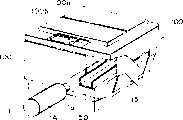
Shown in Figure 4 and 5, toner bottle 1A (main body of bottle or container) is hollow cylinder normally, from the outstanding cylindrical part that forms of an end face that is positioned at its center.The free end face of cylindrical part is decided to be opening 1a, is used for to imaging device (developing apparatus) side discharging toner.
In opening 1a, the seal element 2 that is used for sealed open 1a is pressed into cooperation, and seal element 2 is slidably with automatic opening and closing opening 1a with respect to toner bottle main body 1A axially at toner bottle 1A.
Among Fig. 4, the situation that shown is when opening.
With the inner structure of describing about toner bottle 1A.
Normally the feed element 3 of Ping Ban shape is equipped among the toner bottle 1A, and the inside of toner bottle 1A is divided into two parts, and it exceeds its total length along extending axially of bottle 1A.
Each face at the flat of feed element 3, many protruding 3a (leader) are set, it tilts to extend to opening (when the feed element occupies effectively downwards position towards opening guiding toner, when promptly feed element 3 occupies position among (B) of Fig. 7) with respect to the turning axle a-a of bottle 1A.The tabular zone has the function that supports angled protrusions.An end that leaves the nearest angled protrusions 3a of mouthful 1a extends to the cylindrical part that is defined as opening 1a.At last, along with the rotation of feed element 3, the toner landing is on the surface of nearest protruding 3a and arrive cylindrical part, discharges through opening 1a then.An end that leaves the nearest protruding 3a of mouthful 1a can be extended down to cylindrical part near.
Shown in Fig. 5 (B), on the two sides of feed element 3 plate parts by the rotation symmetry arrangement and protruding 3a is set, like this along with the unidirectional rotation of toner bottle, just can be to opening 1a supply toner.Along with the feed element with the every Rotate 180 of model °, the toner landing that projection is mentioned is on raised surface, like this, opening is supplied with and arrived to toner to opening part gradually.
Therefore, when the feed element rotates with bottle is whole, carry out toner off and on and supply with operation and emissions operation.By the rotation of continuous high speed, toner is supplied with and emissions operation carries out basically continuously.Here, the rotational symmetric meaning is basically about the turning axle symmetry, and promptly the protruding 3a on each face of feed element 3 occupies identical position by the form of 180 ° of rotations basically.
With reference to figure 6,7, will the toner discharging principle of this embodiment toner supply container 1 be described.Fig. 6 is the phantom view that the A-A in Fig. 5 obtains.
More specifically, in this embodiment, be to promote or the rising toner in the space that limits of lift portion (3y zone among Fig. 7 (A)) at bottle and the inside surface that contacts with bottle.When guiding the position of toner downwards, a part of angled protrusions that occupies upper position is defined as lift portion towards opening (for example Fig. 7, (B)) when the feed element occupies.
Plate-like part contact with the inside surface of bottle basically, and prolongs and the setting of the whole length of bottle, and the inside surface of use bottle can promote toner effectively.
The toner that lift portion is not mentioned is by bore portion 3c, and therefore, toner is subjected to castering action and stirs abreast.
Rotation along with bottle, a part of toner that feed element 3 draws or mentions, shown in (B) among Fig. 6, support their plate-like part 3x of (t2 among Fig. 7 (B) and Fig. 6 (B)) by means of angled protrusions 3a and a part, guide to opening down by gravity.
A part of toner that the lift portion of feed element 3 is mentioned is not supplied with or guiding towards opening, but under action of gravity, falls (the t1 among (B) among Fig. 6 and Fig. 7 (B) by bore portion 3c.The effect that falls by bore portion 3c is stirred once more with the toner that makes of the toner that guiding and supply are mentioned.
By above-mentioned effect repeatedly, the toner among the toner bottle 1A is supplied with to discharge port when stirring gradually.At last, partly be extended to opening 1a, shown in Fig. 6 (C), by opening 1a discharging toner from above-mentioned angled protrusions 3a.
Because plate-like part is prolonged basically and the total length of toner bottle 1a, and many angled protrusions 3a are provided with in aforesaid mode, and toner can be supplied with effectively in the well-beaten while.
From the direction perpendicular to turning axle, promptly when inclined protrusions was stretched on the turning axle, they were overlapped.Like this, another angled protrusions is set, can makes by the toner that advances to opening that tilted and be able to further propelling by tight front in angled protrusions.Thus, can stir and supply with toner effectively.
Utilize this embodiment, by suitably selecting the shape of the angled protrusions 3a of setting on the feed element 3, size is arranged and structure, and various toner emission behavior can be provided.
(feed element)
To describe feed element 3 in detail.Feed element 3 prolongs and the main body 1A total length of container basically, thereby the inner space of main body 1A is separated.In this embodiment, feed element 3 is divided into two parts with the main body 1A of container, yet it also can be divided into the space three or four parts.
Preferably, feed element 3 extends the prolongation of opening 1a or opening 1a along the direction of axle.Reason is as follows.Finally, by the toner functions of physical supply of aforesaid angled protrusions 3a, toner discharges through opening 1a.Therefore, feed element 3 preferably extends the opening 1a near main body boss flange part (end wall surface) 3b.
Because feed element 3 just can be avoided toner to rub between feed element 3 and main body 1A and cause solidifying with the whole rotation of container body 1A.
Toner supply container can have the shape of elongation, because can proof strength by the invigoration effect of feed element 3 (as the skeleton that keeps the hollow body shape).For the same reason, can reduce the wall thickness of main body 1A, this can make main body 1A cost reduce and make the material of main body 1A that more selection be arranged.
With reference to figure 7, the toner agitation effects will be described.
Fig. 7 has shown skeleton view (A) and its front view and the left view (B) of the feed element 3 of embodiment of the present invention.
Therefore, guide and supply with a certain amount of toner of mentioning through the rotation of toner bottle to opening by angled protrusions 3a, other toner of mentioning falls through bore portion 3c.Like this, within bottle different motions can appear.
Toner falls through bore portion 3c, and the collision that causes thus disperses the toner that condenses effectively, thereby has improved the flowability of toner in the bottle.The whole length of toner bottle all is provided with bore portion 3c basically, therefore, any part of bottle interior can both very fast raising toner flowability, encircle gratifying emission behavior so the initial period after changing toner container can be carried.For this reason, be unwanted for reaching the standardized pre-rotation of emission behavior, like this reduced to minimum stop time of imaging device (in this cycle can not imaging).
Under traditional colour is adjusted the situation of supply container, form helical raised at the inside surface of bottle, this does not have positive meaning to the toner that disperses to condense, and therefore, must be rotated that estimate to be distributed to until toner can degree of discharge.
Yet according to this embodiment, toner can move effectively on feed element 3 and improve flowability.Even toner becomes bridge and therefore knot is fast, the discharging toner also is no problem.
Preferably, feed element 3 usefulness plastic resin material injection moldings are made, yet also can make with other method and/or different materials.
From recycling container viewpoint, its material preferably with container body 1A identical materials.In more detail, preferable material is ABS, PP, POM, HI-PS.In this embodiment, use HHI-PS.
(angled protrusions)
With reference to figure 8, toner is stirred and supplies with the angled protrusions 3a that performance has appreciable impact with describing.Among Fig. 8, θ is the pitch angle of angled protrusions 3a with respect to turning axle a-a, and size p is the spacing between adjacent inclined projection 3a.In addition, s is a distance of supplying with the toner process by angled protrusions 3a, and b is the width of angled protrusions 3a.
By changing the tiltangle of angled protrusions 3a, can determine the toner supply power selectively.For example, change tiltangle so that precipitous gradient to be set, toner sliding type on angled protrusions 3a approaches vertical drop.In this case, can improve toner slip effect, thereby make the toner supply amount bigger, little apart from s but every angled protrusions toner is supplied with, therefore, feed speed is just littler.When changing tiltangle so that more smooth arrangement to be set, every angled protrusions 3a toner is supplied with elongated apart from s, so feed speed is higher.Yet if tiltangle is too little, toner is not easy landing on angled protrusions 3a.By suitably selecting tiltangle, realize the optimal design of the toner efficiency of supply.According to experiment, preferably 30 °-80 ° of tiltangles, more preferably 45 °-70 °.
In above-mentioned analysis, the toner that angled protrusions forms is supplied with apart from s and is assumed to prominent its length on turning axle.Angled protrusions (when feed element during) downwards towards opening (for example, (B) of Fig. 7) guiding toner by down simultaneously away from the inside of bottle surface.A little structures are favourable.
Do like this, can avoid because the toner that the toner angled protrusions that the inertia of landing causes on angled protrusions is mentioned is mentioned above tight front angled protrusions.Like this, can increase every angled protrusions toner and supply with distance.
On the other hand, shown in Fig. 7 (B), preferably as much as possible near the inside surface of bottle, more preferably it contacts with the inside surface of bottle angled protrusions (for example, (B) of Fig. 7) by last one side.
Do like this, the toner that lift portion is mentioned is basically all by angled protrusions guiding and supply.
Like this, can supply with toner effectively.
(pitch angle and protruding spacing)
All angled protrusions 3a there is no need identical tiltangle.Shown in Fig. 9 (A), for angled protrusions 3a can with differently set angled protrusions 3a (tiltangle 1, θ 2, θ s3) and be provided with differently.Similarly, spacing p also needn't fix, but should be according to angled protrusions 3a (the consistent p1 that sets of spacing, p2, p3) setting.
By being provided with, can control the emission behavior of toner.
In the traditional colour of rotation was as a whole adjusted supply container, the toner discharge capacity changed according to the quantity of remaining toner in the toner bottle, therefore, was difficult to the discharge capacity that keeps constant.This is because in the initial period, and bottle has been filled toner, so toner powder pressure height, and the toner discharge capacity is inevitable big, and stage in the end is equipped with a spot of toner in the bottle, compare with the discharge capacity of initial period, and the toner discharge capacity is minimum.
Yet,,, can produce constant toner discharge capacity by tiltangle s and its spacing p suitably are set according to the structure of this embodiment.
For example, near the spacing p opening 1a is provided with greatly so that low toner mass rate of emission to be provided, and in the part away from opening 1a tiltangle is arranged to little angle to provide for higher toner mass rate of emission.After this manner, for example, the toner bottle axially on can change supply power.Do like this,, can suppress the big tendency of toner discharge capacity, and in the end the toner feed speed becomes bigger antithesis the stage in the initial period.Like this, can guarantee basically that the toner discharge capacity is constant.
(width)
Shown in Fig. 9 (B), similar with spacing p to tiltangle, the width of angled protrusions 3a is optional, supplies with power to adjust toner.
For example, width b is big more, and the quantity of the toner of mentioning is just big more.Yet if it is too big, when making toner supply container, the dress toner will be affected.Therefore, it is set to preferred sizes.
By inventor's experiment and research, the width that shows angled protrusions 3a is about 5-20% of toner bottle inner diameter d preferably.10-15% more preferably.
Finally, width b extends to the opening 1a of discharge port, and the width of ratio open 1a is big.
If it is less than the width of opening 1a, if the efficiency of supply of toner just reduce that it is not less than opening 1a half sufficient practical supply performance just can be provided.
In this embodiment, it the width with opening 1a is identical basically.
(assembly method of toner supply container)
To the assembly method of the toner supply container 1 of embodiment of the present invention be described.
Figure 10 is the skeleton view of illustrating the toner supply container 1 of assembling embodiment 1.The structure of the toner supply container 1 of this embodiment is very simple, can assemble by five parts that connect as shown in figure 10.The main body 1A of container can be easily made by injection molding or blow moulding, seal element 2 can be easily made by injection molding, feed element 3, flange component 4, charging door and cover component 5.In this embodiment, make all parts by injection molding.
As for the method that connects container body 1A and flange component 4, available ultrasonic soldering or vibration welding method perhaps can pass through hot-melt adhesive material or other jointing material with they combinations, like this, can guarantee sealing property.
Perhaps, can use the method that between the outer peripheral surface portion of flange section and cylindrical end, compresses engagement lightly.In this case, twine the outside surface of mate with adhesive tape etc.So, just can easily dismantle the toner bottle.Therefore, can easily reuse toner supply container.
Installation step is as follows.At first, feed element 3 inserts flange 4, and the end of feed element 3 just is clipped between the protruding 4a that is provided with on flange 4 inside surfaces like this.Then, flange component 4 is connected with the main body 1A flange component 4 of container, and with the driving transmission shaft part 3d engagement of seal element 2 with feed element 3.
After this, 4b is filled into main body with toner by the toner filler opening, and will fill cover plate 5 and press among the filler opening 4b, thereby finishes the assembling toner supply container.
Use such installation method, it should be noted feed element 3 and the contacted part of container body 1A inside surface.As mentioned above, if between feed element 3 and body inner surface the slit is arranged, toner passes this slit, causes the efficiency of supply to descend, and the quantity of the residue toner that final stage can not be discharged increases.This is not preferred.Figure 11 has shown that the prevention toner efficiency of supply descends or the embodiment of the structure of increase residue toner quantity.
In the embodiment of Figure 11 (a), the main body of container has two protruding 1e that reinforcing plate type is parallel, and they extend along the parallel direction of axle, and feed element 3 inserts in the slit that forms between the protruding 1e.This structure is adapted to pass through the main body that injection molding is made.Though the free end face of feed element 3 does not mesh with container body 1A, toner does not pass through yet, and therefore can not effectively prevent efficiency of supply decline or the increase of residue toner.For the sense of rotation of container, the protruding 1e of gusset form can only be set in the downstream of relative feed element 3.
Figure 11 (b) has shown another embodiment, and recess 1f wherein is set vertically, and feed element 3 places recess 1f.This embodiment is adapted to pass through the main body that blow moulding is made.The toner efficiency of supply is identical with embodiment (a) with the residue toner.
Figure 12 has illustrated another installation step embodiment.In this embodiment, feed element 3 and flange component 4 unitary, injection-molded moulding are inserted into whole element among the main body 1A then.Do like this, the quantity of parts can be reduced to four parts.
Thereby, according to embodiment of the present invention, can be with various manufacture methods and installation method.In addition, because different with traditional toner supply container, the agitating element in the toner container does not rotate, and does not increase the problem that stirs required moment of torsion so do not exist.
Do not use supporting member etc. for bearing the t shaft, reduced departmental cost and also can avoid condensing owing to the toner particle that the slip effect at supporting part causes.
(recycling of toner supply container)
To the recycling of the toner supply container 1 that uses be described.For the easy-off purpose, main body 1A and flange component 4 are connected by adhesive tape.Disassembling section is opposite with assembly manipulation.In more detail, the seal element 2 of at first dismantling, the adhesive tape of dismantling again, thus main body 1A is divided into four parts as shown in figure 12.With air flow cleaning main body 1A, with the feed element 3 of protruding 3a, flange component 4, seal element 2 and filling cover plate 5.Subsequently, they are ressembled in the container, fill the toner of scheduled volume, thereby finish recycling.
The part of short of wearing and tearing, utilization factor will be high again.Under normal situation, the part that will replace not.Because the part that does not have labyrinth or do not have air to be not easy to arrive.So this structure is suitable for air purification.Therefore, can simply and surely clear up.It is identical with new toner bottle that this toner is supplied with performance.
On the other hand, the toner supply container 1 of use may be crushed, and it all is possible reducing material.Even main body 1A, feed element 3, flange component 4, seal element 2 is made with the different material of filling cover plate 5 usefulness, and they also are easy to be divided into various piece so.The situation that this helps reusing.In addition, the toner supply container 1 of embodiment of the present invention makes the material of feed element 3 that very big choice be arranged.Might make all parts with identical materials.Under the sort of situation, make up container body 1A by ultrasonic soldering, so when utilizing container body again, its is understood crushed and does not dismantle and utilize.Material is polypropylene or tygon preferably, because comprise seal element 2, all is general material.
(rotation drives structure)
To the device of the transmission driving force of rotating rotary container main body 1A be described.For this device, can be with various known mechanical hook-ups.Figure 13 and 14 has shown an embodiment.
In Figure 13, protruding 3f is arranged on the outside surface of flange section 3b, and it meshes to bear rotary driving force with the driving running part that is arranged in the imaging device primary clustering.Figure 14 has shown another embodiment, and as shown in this figure, wherein at the circumference surrounding edge formative gear part 1d of main body 1A, gear parts 1d is meshed to bear rotary driving force with driven wheel in being arranged on the imaging device primary clustering.
In the embodiment shown in Figure 15, seal element 2 also plays the rotary driving force conveying element.Seal element 2 comprises hermetic unit 2c, flange section 2d, and driving force is born part 2e and lock part 2f.
The internal diameter of the external diameter ratio open 1a of hermetic unit 2c is big slightly, it is pressed among the opening 1a blocked by flange section 2d up to it.
After toner supply container 1 is packed in the critical piece 100 of imaging device, lock part 11 is moved to the center of seal element 2 by opening and closing Qianmen or operating rod.The main body 1A of container moves in the left side in figure, the engagement of the lock part 2f of while lock part 11 and seal element 2, thereby seal element 2 mediation automatically discharges and when putting in the critical piece from container when toner, and rotary driving force is accepted part 2e from the driving force that the drive unit 12 of imaging device primary clustering is delivered to seal element 2.Seal element 2 further comprise from the whole non-circular shaft part 3d that extend of feed element 3 and along the direction of axle slide with the corresponding rectangular opening 2g of shaft portion 3d engagement.Even after opening was opened, they also kept being engaged with each other.
By seal element 2, rotary driving force is sent on feed element 3 and the main body 1A, thereby supplies with and the discharging toner, and by shaft portion 3d, they rotate together.
In the time will taking out toner supply container 1, operation is opposite.In more detail, open the Qianmen or by the operation pull bar, the main body 1A of container pushes ahead, like this, seal element 2 presses into opening 1a with sealed open 1a again.
(embodiment 2)
With reference to Figure 16, second embodiment will be described.
In Figure 16, the angled protrusions 3a on the plate-like part opposite side is the minute surface symmetric relation with respect to the turning axle a-a of toner bottle 1A.
In traditional embodiment, the sense of rotation of toner bottle 1A to be decided to be a direction in order to discharge toner (supply) by toner bottle 1A rotation discharging toner.
Under the traditional colour adjustment situation that has the spiral fashion gusset on the toner bottle inside surface, have only when bottle rotates by certain predetermined direction, could supply with toner.
Yet under the situation of toner supply container 1 of the present invention, the angled protrusions 3a shown in Figure 16 is possible by minute surface symmetric mode structure arranged.Use this arrangement, can discharge toner by direction rotation arbitrarily.
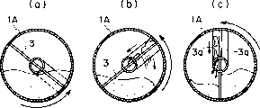
Figure 17 has shown the right handed situation of toner bottle 1A, and Figure 18 has shown the situation that toner bottle 1A counterclockwise rotates.
At Figure 17, in 18, by (a) among these figure and the step (b) have drawing of feed element 3 or lift portion that toner is drained out.Then, the toner landing is on the angled protrusions 3a of opening (C).
As shown in these figures, angled protrusions 3a presses the minute surface symmetric mode and arranges, and all can discharge toner by any one direction rotation.Yet, the toner emissions operation by on any direction one only occur once in the rotation fully, these are different with first embodiment.
Utilize these to arrange, can reach following favourable effect.
By the sense of rotation of periodic variation bottle and feed element, the impact (facilitation) that produces on this conversion basis can significantly improve the mixing effect of toner in the container effectively.Simultaneously, the toner particle that is deposited on the bottle inside surface is fallen, therefore, can significantly reduce the quantity of obsolete residue toner.
(other embodiment)
The present invention is not limited to above-mentioned embodiment, also various variations can be arranged.
In the above-described embodiment, angled protrusions is vertically to extend from disk-shaped regions basically, and ready-made angled protrusions 3a can be by Figure 19 to improving shown in Figure 23.
Among Figure 19, the side end of protruding 3a bends to " L " type to block toner, and in this case, the quantity of the toner of landing on angled protrusions 3a is bigger than above-mentioned embodiment.
Figure 20,21 have shown other embodiment, the xsect of angled protrusions 3a is semicircle, ellipse etc., promptly the smooth curved xsect in this case, can surely hold toner, thereby, improve toner and supplied with power.In addition, reduce the quantity that is deposited on lip-deep toner, so just reduced obsolete residue toner.
Shown in Figure 22 and 23, change the width b of (reduce or increase) angled protrusions 3a gradually, can adjust the toner supply amount like this.Under the situation of Figure 22, can guide on the top of angled protrusions and supply with a large amount of toners, in the bottom, the fallen part of toner is greater than guiding or the part supplied with.This can strengthen the toner mixing effect effectively, and adjusts the quantity of supplying with toner.
Because with the shaped design of angled protrusions 3a is big scope, the toner supply amount can suitably be set to reach predetermined toner emission behavior intensity.
The position of opening 1a (toner is by its discharging) is not limited to the vertical end surfaces of container body 1A, but as shown in figure 24, it also can be arranged in the face of cylinder of main body.
In this case, seal element 2 is regarded opening 1a as, the packing ring 2b that it comprises the arc valve 2a that conforms with main body 1A outer shape and is bonded to valve 2a inside surface.
To the toner emission behavior result of experiment of toner supply container in the above-mentioned embodiment be described.
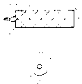
(test 1)
In the toner supply container of first embodiment (Fig. 4-7), fill the 2000g toner, and under high temperature and high humidity atmosphere (40 ℃ of humidity, humidity 80%), upper shed 1a in toner supply container bottom side was vertically placed 40 days down.
So, owing to absorbed moisture content, the toner powder in the toner bottle has just had very poor flowability.
Because container is placed in the bottom with opening 1a, so because gravity causes toner to be squeezed in the bottom.After harsh conditions was placed, the toner bottle had no quiveringly in the critical piece of charging apparatus slowly, then with predetermined gyro frequency (30rpm) rotation.Rotation toner bottle is measured the toner discharging simultaneously always till all toners all give off.
Figure 27 has shown the result that the toner discharge capacity is measured.Ordinate is an accumulation toner discharge capacity (g), and horizontal ordinate is the discharging used time (second) of toner, i.e. the time (second) of bottle rotation.
(test 2)
As shown in figure 25, feed element 3 all bore portion 3c close, so the inside of bottle is divided into the chamber basically fully.Under identical condition, carry out identical test.Figure 27 has shown the result who measures the toner discharge capacity.
(structure of Comparative Examples 1)
For the toner bottle that has the spiral fashion gusset at inside surface, under identical condition, carry out identical test.
Figure 27 has also shown the result who measures the toner discharge capacity.
As will be from Figure 27 understood, the toner bottle for test 1 is equipped with bore portion 3c in its feed element 3, and be no problem in the initial period of rotation.Do not have the situation of bore portion (test 2), emission behavior is poor slightly.In more detail, up to about 150 seconds, discharge capacity was still poor slightly.
Under the situation of test 2, bottle interior is cut apart fully, and therefore, toner can not pass through the feed element.What obviously increase is the starting torque of driving motor.So tendency that driving motor just might damage and may need to change.For fear of these, need to use powerful driving motor, this will cause cost to increase.
On the other hand, at existing embodiment with under the situation that the toner bottle rotates,, the toner discharging is arranged just up to about 200 seconds in the initial period.Along with the continuous rotation of bottle, just begin discharging from beginning 200 seconds in the past toners.
Verified, in test 1 and 2, even bottle is preserved under harsh conditions and bottle in toner Cheng Qiao (though in the performance of test in 2 than the poor performance in test 2), gather thing also from the beginning (rotation initial stage) just discharge.
As mentioned above, embodiment of the present invention possess following useful effect.
(1) quantity in the parts that constitute the toner bottle is few, and the quantity of required installation step is also few, thereby can reduce production costs.
(2) structure with traditional is different, does not use supporting sealing device, reduces required rotary torque.
(3) structure with traditional is different, does not use supporting sealing device, tendency that can corresponding minimizing toner seepage.
(4) by from bigger range of choice, selecting the shape and the arrangement of projection, can easily adjust toner discharge capacity and a mass rate of emission.
(5) rotating the tank capacity that can both discharge toner by any direction improves.
(6) owing to be provided with the feed element, strengthened the physical strength of main body, and can reduce the thickness of container body in the inside of container body.
(7), also can suitably discharge toner from the initial period of rotation even the toner in bottle contains the bulk particle.
(8) can reach the constant number emission behavior.
(9) can be with the critical piece miniaturization of imaging device, thus the cost of toner supply container driving element reduced.
(10) can easily reuse employed toner supply container.
(11) because toner stirring efficiency height can not produce the toner bridge in container body.
(12), be simple and easy so utilize metal pattern manufacturing metal pattern or mould because the toner bottle does not have the spiral fashion gusset in the inboard of toner bottle.
Though with reference to structrual description disclosed herein the present invention, it is not limited to the details of front, and the application is intended to, and is included in improvement in the object of the invention and variation and plays to cover and meet following claim scope.
Claims (20)
1. toner supply container that is removably mounted on the imaging device, above-mentioned toner supply container comprises:
One is used to hold the container body of toner, and the said vesse body has the opening portion of permission toner from wherein discharging; And
Be arranged on the feed member in the said vesse body, it is used for supplying with towards above-mentioned opening portion the toner of said vesse body,
It is characterized by, above-mentioned feed member comprises a rotatable discoid component along the longitudinal extension of said vesse body, above-mentioned discoid component comprises a projection and a through hole, this projection is extended obliquely with respect to the rotation of above-mentioned discoid component, guide toner with basic rotation towards above-mentioned opening portion with above-mentioned discoid component, this through hole allows the toner on the above-mentioned discoid component to fall along with the rotation of above-mentioned discoid component effectively, thus agitation of toner.
2. toner supply container as claimed in claim 1 is characterized by, and in a side of above-mentioned discoid component, in different lengthwise positions, many this projections is set.
3. toner supply container as claimed in claim 1 is characterized by, and in the both sides of above-mentioned discoid component, in different lengthwise positions, many this projections is set.
4. toner supply container as claimed in claim 3 is characterized by, and in the both sides of above-mentioned discoid component above-mentioned projection is set, so that twice toner discharging action carried out in a whole rotation of enclosing of above-mentioned discoid component.
5. as each toner supply container of claim 2~4, it is characterized by, in above-mentioned many projections one basically with above-mentioned opening portion near or adjacent.
6. as each toner supply container of claim 2~4, it is characterized by, many this projections are set, so that partly with respect to the longitudinal overlap of above-mentioned discoid component.
7. as each toner supply container of claim 2~4, it is characterized by, many above-mentioned projections are set, and between each adjacent projection of above-mentioned projection, above-mentioned through hole are set.
8. toner supply container as claimed in claim 5, it further comprises the extension of a hollow of extending from above-mentioned opening portion, there is an opening above-mentioned extension at its free end, to allow the discharging of toner.
9. toner supply container that is removably mounted on the imaging device, above-mentioned toner supply container comprises:
One is used to hold the rotatable container body of toner, and the said vesse body has the opening portion of permission toner from wherein discharging; And
Be arranged on the feed member in the said vesse body, it by its with the rotation of the one of said vesse body the toner in the above-mentioned opening portion supply said vesse body,
It is characterized by, above-mentioned feed member comprises a discoid component along the longitudinal extension of said vesse body, above-mentioned discoid component comprises a projection and a through hole, this projection is extended obliquely with respect to the rotation of above-mentioned discoid component, guide toner with rotation towards above-mentioned opening portion with above-mentioned discoid component, this through hole allows the toner on the above-mentioned discoid component to fall along with the rotation of above-mentioned discoid component effectively, thus agitation of toner.
10. toner supply container as claimed in claim 9 is characterized by, and in a side of above-mentioned discoid component, in different lengthwise positions, many this projections is set.
11. toner supply container as claimed in claim 9 is characterized by, and in the both sides of above-mentioned discoid component, in different lengthwise positions, many this projections is set.
12. the toner supply container as claim 11 is characterized by, and in the both sides of above-mentioned discoid component above-mentioned projection is set, so that twice toner discharging action carried out in a whole rotation of enclosing of above-mentioned discoid component.
13. each the toner supply container as claim 10~12 is characterized by, in above-mentioned many projections one basic with above-mentioned opening portion near or adjacent.
14. toner supply container as claimed in claim 9 is characterized by, said vesse is columniform basically.
15. toner supply container as claimed in claim 9 is characterized by, above-mentioned discoid component will so be placed, so that contacts with the interior perimeter surface of said vesse body or close with it.
16. toner supply container as claimed in claim 9 is characterized by, above-mentioned discoid component extends along the whole length of said vesse body substantially.
17. toner supply container as claimed in claim 9 is characterized by, above-mentioned discoid component is divided into two basic parts that equate along diameter with the inside of said vesse.
18. each the toner supply container as claim 12~12 is characterized by, and many this projections are set, so that partly with respect to the longitudinal overlap of above-mentioned discoid component.
19. each the toner supply container as claim 10~12 is characterized by, and many above-mentioned projections is set, and between each adjacent projection of above-mentioned projection above-mentioned through hole is set.
20. as the toner supply container of claim 13, it further comprises the extension of a hollow of extending from above-mentioned opening portion, there is an opening above-mentioned extension at its free end, to allow the discharging of toner.
Applications Claiming Priority (4)
| Application Number | Priority Date | Filing Date | Title |
|---|---|---|---|
| JP042536/2001 | 2001-02-19 | ||
| JP2001042536 | 2001-02-19 | ||
| JP2001174179 | 2001-06-08 | ||
| JP174179/2001 | 2001-06-08 |
Related Child Applications (1)
| Application Number | Title | Priority Date | Filing Date |
|---|---|---|---|
| CNB200510007844XA Division CN100414452C (en) | 2001-02-19 | 2002-02-19 | Toner supply container and image forming apparatus |
Publications (2)
| Publication Number | Publication Date |
|---|---|
| CN1374569A CN1374569A (en) | 2002-10-16 |
| CN1237413C true CN1237413C (en) | 2006-01-18 |
Family
ID=26609663
Family Applications (2)
| Application Number | Title | Priority Date | Filing Date |
|---|---|---|---|
| CNB021185018A Expired - Fee Related CN1237413C (en) | 2001-02-19 | 2002-02-19 | Toner supply container and imaging device |
| CNB200510007844XA Expired - Fee Related CN100414452C (en) | 2001-02-19 | 2002-02-19 | Toner supply container and image forming apparatus |
Family Applications After (1)
| Application Number | Title | Priority Date | Filing Date |
|---|---|---|---|
| CNB200510007844XA Expired - Fee Related CN100414452C (en) | 2001-02-19 | 2002-02-19 | Toner supply container and image forming apparatus |
Country Status (5)
| Country | Link |
|---|---|
| US (3) | US7039347B2 (en) |
| EP (1) | EP1233311B1 (en) |
| JP (1) | JP3884974B2 (en) |
| KR (2) | KR100462729B1 (en) |
| CN (2) | CN1237413C (en) |
Families Citing this family (59)
| Publication number | Priority date | Publication date | Assignee | Title |
|---|---|---|---|---|
| JP3450741B2 (en) * | 1999-03-29 | 2003-09-29 | キヤノン株式会社 | Toner supply container |
| EP1993003B1 (en) * | 2001-02-19 | 2011-08-24 | Canon Kabushiki Kaisha | Toner supply container and toner supply system |
| US6990301B2 (en) * | 2001-02-19 | 2006-01-24 | Canon Kabushiki Kaisha | Sealing member, toner accommodating container and image forming apparatus |
| US6922540B2 (en) * | 2001-10-03 | 2005-07-26 | Canon Kabushiki Kaisha | Developer supply kit |
| US6665505B2 (en) | 2001-12-20 | 2003-12-16 | Xerox Corporation | Dry ink replenishment bottle with internal plug agitation device |
| EP1357441B1 (en) | 2002-04-24 | 2007-03-14 | Canon Kabushiki Kaisha | Developer supply container |
| US6987942B2 (en) * | 2002-04-24 | 2006-01-17 | Canon Kabushiki Kaisha | Toner supply kit |
| JP4143325B2 (en) * | 2002-04-26 | 2008-09-03 | キヤノン株式会社 | Toner supply container and drive transmission member |
| JP4422956B2 (en) * | 2002-10-16 | 2010-03-03 | キヤノン株式会社 | Developer supply mechanism |
| JP4208637B2 (en) | 2003-05-01 | 2009-01-14 | キヤノン株式会社 | Developer supply container |
| JP4208645B2 (en) * | 2003-06-03 | 2009-01-14 | キヤノン株式会社 | Developer supply container |
| JP4343625B2 (en) * | 2003-08-29 | 2009-10-14 | キヤノン株式会社 | Developer supply container |
| US7155138B2 (en) * | 2003-12-22 | 2006-12-26 | Canon Kabushiki Kaisha | Developer supply container |
| US7260346B2 (en) * | 2004-05-24 | 2007-08-21 | Himes William D | Developer cartridge with a geometry configured to open and close a shutter |
| JP4589045B2 (en) | 2004-07-15 | 2010-12-01 | 株式会社東芝 | Toner container |
| JP2006126635A (en) * | 2004-10-29 | 2006-05-18 | Kyocera Mita Corp | Color image forming apparatus |
| JP4579655B2 (en) * | 2004-11-12 | 2010-11-10 | キヤノン株式会社 | Toner cartridge and image forming apparatus |
| JP4636853B2 (en) * | 2004-11-12 | 2011-02-23 | キヤノン株式会社 | Developer supply container and image forming apparatus |
| JP4681854B2 (en) * | 2004-11-12 | 2011-05-11 | キヤノン株式会社 | Sealing member, toner supply container, and image forming apparatus |
| US7206528B2 (en) * | 2004-11-12 | 2007-04-17 | Kabushiki Kaisha Toshiba | Image forming apparatus and image forming method |
| JP4621019B2 (en) * | 2004-12-17 | 2011-01-26 | キヤノン株式会社 | Developer supply container |
| US7460819B2 (en) * | 2005-12-21 | 2008-12-02 | Kabushiki Kaisha Toshiba | Toner cartridge and image forming apparatus |
| WO2007072991A1 (en) * | 2005-12-21 | 2007-06-28 | Canon Kabushiki Kaisha | Developer supply container and developer supplying system |
| JP4850677B2 (en) * | 2005-12-21 | 2012-01-11 | キヤノン株式会社 | Developer supply container |
| WO2007100141A1 (en) * | 2006-02-28 | 2007-09-07 | Canon Kabushiki Kaisha | Powder-filling device, powder-filling method, and process cartridge |
| US7729644B2 (en) | 2006-05-11 | 2010-06-01 | Katun Corporation | Toner cartridge |
| CN101479669B (en) * | 2006-05-23 | 2011-12-07 | 佳能株式会社 | Developer replenishing container and developer replenishing system |
| EP1965272B1 (en) * | 2007-02-28 | 2014-11-19 | Brother Kogyo Kabushiki Kaisha | Cartridge comprising an engagement gear and a rotation body |
| KR100899350B1 (en) * | 2008-02-22 | 2009-05-27 | 삼성전자주식회사 | Developing apparatus, image forming apparatus having the same, and toner suppling method for a developing apparatus |
| JP4995126B2 (en) * | 2008-03-13 | 2012-08-08 | キヤノン株式会社 | Developer supply device and developer supply system |
| JP4600560B2 (en) * | 2008-09-26 | 2010-12-15 | 富士ゼロックス株式会社 | Storage container and image forming apparatus using the same |
| US8290407B2 (en) * | 2009-01-30 | 2012-10-16 | Kyocera Mita Corporation | Toner supply apparatus with a drive member for driving an agitator and with a film covering the periphery of the drive member |
| US7904005B2 (en) * | 2009-02-26 | 2011-03-08 | Fuji Xerox Co., Ltd. | Image forming apparatus |
| EP3336610B1 (en) * | 2009-03-30 | 2019-08-21 | Canon Kabushiki Kaisha | Developer supply container and developer supplying system |
| JP5335540B2 (en) | 2009-04-28 | 2013-11-06 | キヤノン株式会社 | Developer supply device |
| JP5300599B2 (en) * | 2009-06-01 | 2013-09-25 | キヤノン株式会社 | Developer supply device |
| KR101608062B1 (en) * | 2009-08-28 | 2016-03-31 | 삼성전자주식회사 | Detachable toner cartridge and image forming apparatus having the same |
| JP5649325B2 (en) * | 2010-04-16 | 2015-01-07 | 株式会社沖データ | Developer container, developing device, and image forming apparatus |
| CA2973610C (en) | 2010-12-03 | 2023-01-10 | Ricoh Company, Ltd. | Powder container, powder supply device and image forming apparatus |
| JP6083954B2 (en) | 2011-06-06 | 2017-02-22 | キヤノン株式会社 | Developer supply container and developer supply system |
| MX349424B (en) | 2011-11-25 | 2017-07-28 | Ricoh Co Ltd | Powder container and image forming apparatus. |
| JP5950611B2 (en) | 2012-02-17 | 2016-07-13 | キヤノン株式会社 | Developer supply container and developer supply system |
| US8737887B2 (en) * | 2012-04-27 | 2014-05-27 | Lexmark International, Inc. | Shutter assembly for a toner container |
| TWI581078B (en) * | 2012-06-03 | 2017-05-01 | 理光股份有限公司 | Powder container and image forming apparatus |
| JP5596092B2 (en) * | 2012-08-29 | 2014-09-24 | 京セラドキュメントソリューションズ株式会社 | Toner container and image forming apparatus |
| JP5709946B2 (en) * | 2012-09-14 | 2015-04-30 | キヤノン株式会社 | Developer supply device and image forming apparatus |
| US9465317B2 (en) | 2013-02-25 | 2016-10-11 | Ricoh Company, Ltd. | Nozzle insertion member, powder container, and image forming apparatus |
| WO2014142353A1 (en) | 2013-03-14 | 2014-09-18 | Ricoh Company, Limited | Toner container and image forming apparatus |
| RU2615797C1 (en) | 2013-03-15 | 2017-04-11 | Рикох Компани, Лимитед | Container for powder and image forming apparatus |
| JP5972236B2 (en) * | 2013-08-27 | 2016-08-17 | 京セラドキュメントソリューションズ株式会社 | Stirring mechanism, toner container, and image forming apparatus |
| JP6584228B2 (en) | 2015-08-27 | 2019-10-02 | キヤノン株式会社 | Developer supply container |
| TWI714264B (en) * | 2016-08-26 | 2020-12-21 | 日商佳能股份有限公司 | Drum unit, cartridge, electrophotographic image forming apparatus and coupling member |
| TWI798600B (en) * | 2016-08-26 | 2023-04-11 | 日商佳能股份有限公司 | Drum unit, cartridge, electrophotographic image forming apparatus and coupling member |
| GB2568445B (en) | 2016-08-26 | 2021-09-15 | Canon Kk | Drum unit, cartridge, electrophotographic image forming apparatus and coupling member |
| TWI713830B (en) * | 2016-08-26 | 2020-12-21 | 日商佳能股份有限公司 | Drum unit, cartridge, electrophotographic image forming apparatus and coupling member |
| JP7146506B2 (en) * | 2018-07-31 | 2022-10-04 | キヤノン株式会社 | Developer storage unit, developing device, process cartridge |
| US10642189B2 (en) * | 2018-07-31 | 2020-05-05 | Canon Kabushiki Kaisha | Developer container unit, developing apparatus, and process cartridge |
| JP7175678B2 (en) * | 2018-08-30 | 2022-11-21 | キヤノン株式会社 | developer supply container |
| BR112021003542A2 (en) | 2018-08-30 | 2021-05-18 | Hewlett-Packard Development Company, L.P. | print refill devices |
Family Cites Families (31)
| Publication number | Priority date | Publication date | Assignee | Title |
|---|---|---|---|---|
| JPH01219862A (en) * | 1988-02-29 | 1989-09-01 | Toshiba Corp | Developer replenishing device |
| JPH04260075A (en) | 1991-02-15 | 1992-09-16 | Ricoh Co Ltd | Developing device |
| JPH05249825A (en) | 1992-03-09 | 1993-09-28 | Matsushita Electric Ind Co Ltd | Toner container and developing device |
| JPH06161246A (en) * | 1992-11-27 | 1994-06-07 | Minolta Camera Co Ltd | Toner replenishing device |
| JP3320152B2 (en) | 1993-07-28 | 2002-09-03 | 株式会社リコー | Toner storage container and toner supply device |
| JPH07104572A (en) | 1993-10-05 | 1995-04-21 | Ricoh Co Ltd | Developing device |
| JP3229088B2 (en) | 1993-10-14 | 2001-11-12 | 三菱重工業株式会社 | Automatic gas sampling method and automatic gas analysis method |
| JP3387596B2 (en) * | 1993-12-28 | 2003-03-17 | キヤノン株式会社 | Toner cartridge and developer receiving device |
| EP0661609B1 (en) * | 1993-12-28 | 2000-03-29 | Canon Kabushiki Kaisha | Developer cartridge and remanufacturing method therefor |
| JPH07253710A (en) | 1994-03-15 | 1995-10-03 | Mita Ind Co Ltd | Toner hopper and developing device including the same |
| JP3364632B2 (en) * | 1994-11-08 | 2003-01-08 | 株式会社リコー | Toner supply device |
| JPH09211955A (en) * | 1996-02-08 | 1997-08-15 | Ricoh Co Ltd | Stirring member for toner supplying device |
| US5907756A (en) * | 1996-08-07 | 1999-05-25 | Minolta Co., Ltd. | Toner replenishment device and toner bottle |
| JP3545919B2 (en) | 1996-10-22 | 2004-07-21 | 株式会社リコー | Toner supply container, image forming apparatus, and method of recycling and using parts constituting toner supply container |
| US5890040A (en) | 1997-01-14 | 1999-03-30 | Konica Corporation | Developer cartridge and developer replenishing apparatus |
| JP3861428B2 (en) | 1997-01-14 | 2006-12-20 | コニカミノルタホールディングス株式会社 | Toner storage container and toner supply device |
| JP3907273B2 (en) * | 1997-06-05 | 2007-04-18 | キヤノン株式会社 | Toner replenishing method, toner container, and electrophotographic image forming apparatus |
| JP3697065B2 (en) * | 1997-06-19 | 2005-09-21 | キヤノン株式会社 | Toner supply container and electrophotographic image forming apparatus |
| JP3571873B2 (en) * | 1997-06-27 | 2004-09-29 | キヤノン株式会社 | Toner conveying blade and toner supply container |
| JP3408166B2 (en) * | 1997-09-30 | 2003-05-19 | キヤノン株式会社 | Toner supply container and electrophotographic image forming apparatus |
| US5918095A (en) * | 1998-07-29 | 1999-06-29 | General Plastic Industrial Co., Ltd. | Developer dispensing container |
| JP3450757B2 (en) * | 1998-09-22 | 2003-09-29 | キヤノン株式会社 | Toner supply container |
| CA2300651C (en) | 1999-03-17 | 2002-12-10 | Canon Kabushiki Kaisha | Toner container and toner replenishing mechanism |
| JP3450741B2 (en) * | 1999-03-29 | 2003-09-29 | キヤノン株式会社 | Toner supply container |
| JP3384368B2 (en) * | 1999-09-22 | 2003-03-10 | 日本電気株式会社 | Toner supply device |
| US6470163B1 (en) | 1999-10-27 | 2002-10-22 | Canon Kabushiki Kaisha | Developer stirring member, assembly method and recycling method for the same |
| JP3403132B2 (en) | 1999-10-29 | 2003-05-06 | キヤノン株式会社 | Toner stirring blade and toner supply container |
| US6229976B1 (en) * | 2000-02-01 | 2001-05-08 | Toshiba Tec Kabushiki Kaisha | Exchangeable toner cartridge having an auger and a regulation member |
| JP3927767B2 (en) | 2000-07-12 | 2007-06-13 | キヤノン株式会社 | Toner supply container and method for regenerating toner supply container |
| US6704533B2 (en) * | 2000-12-08 | 2004-03-09 | Canon Kabushiki Kaisha | Toner supply container and stirring rotation member |
| JP3907408B2 (en) * | 2000-12-28 | 2007-04-18 | キヤノン株式会社 | Image forming apparatus |
-
2002
- 2002-02-18 EP EP02003652A patent/EP1233311B1/en not_active Expired - Lifetime
- 2002-02-19 US US10/076,455 patent/US7039347B2/en not_active Expired - Lifetime
- 2002-02-19 JP JP2002042393A patent/JP3884974B2/en not_active Expired - Fee Related
- 2002-02-19 KR KR10-2002-0008634A patent/KR100462729B1/en not_active IP Right Cessation
- 2002-02-19 CN CNB021185018A patent/CN1237413C/en not_active Expired - Fee Related
- 2002-02-19 CN CNB200510007844XA patent/CN100414452C/en not_active Expired - Fee Related
-
2004
- 2004-03-22 US US10/805,359 patent/US6944417B2/en not_active Expired - Lifetime
- 2004-03-29 KR KR10-2004-0021114A patent/KR100454835B1/en not_active IP Right Cessation
-
2005
- 2005-11-14 US US11/271,803 patent/US7116931B2/en not_active Expired - Lifetime
Also Published As
| Publication number | Publication date |
|---|---|
| JP3884974B2 (en) | 2007-02-21 |
| US7039347B2 (en) | 2006-05-02 |
| CN1374569A (en) | 2002-10-16 |
| KR100462729B1 (en) | 2004-12-20 |
| EP1233311A3 (en) | 2009-04-22 |
| CN100414452C (en) | 2008-08-27 |
| JP2003057931A (en) | 2003-02-28 |
| US20040223791A1 (en) | 2004-11-11 |
| KR20020067984A (en) | 2002-08-24 |
| US6944417B2 (en) | 2005-09-13 |
| KR20040043143A (en) | 2004-05-22 |
| CN1661490A (en) | 2005-08-31 |
| US7116931B2 (en) | 2006-10-03 |
| EP1233311A2 (en) | 2002-08-21 |
| KR100454835B1 (en) | 2004-11-03 |
| US20060062604A1 (en) | 2006-03-23 |
| EP1233311B1 (en) | 2012-08-29 |
| US20020122676A1 (en) | 2002-09-05 |
Similar Documents
| Publication | Publication Date | Title |
|---|---|---|
| CN1237413C (en) | Toner supply container and imaging device | |
| CN1145854C (en) | Image forming apparatus and toner replenishing device therefor | |
| CN1118722C (en) | Toner supply container, sealing member and electrophotographic image forming apparatus | |
| CN2606378Y (en) | Sealed element | |
| CN1109274C (en) | Toner supply container and electrophotographic image forming apparatus | |
| CN1066545C (en) | Developer cartridge and remanufacturing method therefor | |
| CN1118723C (en) | Toner accommodating container part, toner supply container and electrophotographic image forming apparatus | |
| CN1129039C (en) | Image forming apparatus and toner housing container | |
| CN2731503Y (en) | Image forming appts. | |
| CN1149446C (en) | Toner supply container and electrophotographic image forming apparatus | |
| CN1119715C (en) | Toner container, imaging method and device with same | |
| CN1143182C (en) | Toner container and toner supplementary mechanism | |
| CN1427312A (en) | Image forming device and treating tube and developing unit for image forming device | |
| CN1837979A (en) | Development device, and process cartridge and image forming apparatus using the device | |
| CN100345065C (en) | Processing box and imaging equipment | |
| CN1837990A (en) | Cleaning unit, process cartridge using cleaning unit, and image forming apparatus using cleaning unit | |
| CN1841229A (en) | Development device, and process cartridge and image forming apparatus using the device | |
| CN1627201A (en) | Developer supply device and image forming apparatus including the same | |
| CN1499318A (en) | Renewing method of processor cartridge | |
| CN101042558A (en) | Support element, toner replenishing device, toner supply apparatus, and image forming apparatus | |
| CN1136502A (en) | Ink box and treating card box | |
| CN1070296C (en) | Imaging instrument | |
| CN1837978A (en) | Process cartridge and image forming apparatus using the same | |
| CN1497385A (en) | Retreading method of developer supply device | |
| CN1229698C (en) | Element for receiving driving force, and the driving mechanism |
Legal Events
| Date | Code | Title | Description |
|---|---|---|---|
| C10 | Entry into substantive examination | ||
| SE01 | Entry into force of request for substantive examination | ||
| C06 | Publication | ||
| PB01 | Publication | ||
| C10 | Entry into substantive examination | ||
| SE01 | Entry into force of request for substantive examination | ||
| C14 | Grant of patent or utility model | ||
| GR01 | Patent grant | ||
| CF01 | Termination of patent right due to non-payment of annual fee |
Granted publication date: 20060118 Termination date: 20210219 |
|
| CF01 | Termination of patent right due to non-payment of annual fee |