CN1236231A - Radio transmission system and transmission method - Google Patents
Radio transmission system and transmission method Download PDFInfo
- Publication number
- CN1236231A CN1236231A CN99107445A CN99107445A CN1236231A CN 1236231 A CN1236231 A CN 1236231A CN 99107445 A CN99107445 A CN 99107445A CN 99107445 A CN99107445 A CN 99107445A CN 1236231 A CN1236231 A CN 1236231A
- Authority
- CN
- China
- Prior art keywords
- signal
- information
- message segments
- power
- transmitted power
- Prior art date
- Legal status (The legal status is an assumption and is not a legal conclusion. Google has not performed a legal analysis and makes no representation as to the accuracy of the status listed.)
- Pending
Links
Images


Classifications
-
- H—ELECTRICITY
- H04—ELECTRIC COMMUNICATION TECHNIQUE
- H04L—TRANSMISSION OF DIGITAL INFORMATION, e.g. TELEGRAPHIC COMMUNICATION
- H04L1/00—Arrangements for detecting or preventing errors in the information received
- H04L1/0001—Systems modifying transmission characteristics according to link quality, e.g. power backoff
- H04L1/0023—Systems modifying transmission characteristics according to link quality, e.g. power backoff characterised by the signalling
- H04L1/0026—Transmission of channel quality indication
-
- H—ELECTRICITY
- H04—ELECTRIC COMMUNICATION TECHNIQUE
- H04W—WIRELESS COMMUNICATION NETWORKS
- H04W52/00—Power management, e.g. TPC [Transmission Power Control], power saving or power classes
- H04W52/04—TPC
-
- H—ELECTRICITY
- H04—ELECTRIC COMMUNICATION TECHNIQUE
- H04W—WIRELESS COMMUNICATION NETWORKS
- H04W52/00—Power management, e.g. TPC [Transmission Power Control], power saving or power classes
- H04W52/04—TPC
- H04W52/18—TPC being performed according to specific parameters
- H04W52/28—TPC being performed according to specific parameters using user profile, e.g. mobile speed, priority or network state, e.g. standby, idle or non transmission
- H04W52/281—TPC being performed according to specific parameters using user profile, e.g. mobile speed, priority or network state, e.g. standby, idle or non transmission taking into account user or data type priority
-
- H—ELECTRICITY
- H04—ELECTRIC COMMUNICATION TECHNIQUE
- H04L—TRANSMISSION OF DIGITAL INFORMATION, e.g. TELEGRAPHIC COMMUNICATION
- H04L1/00—Arrangements for detecting or preventing errors in the information received
- H04L1/0001—Systems modifying transmission characteristics according to link quality, e.g. power backoff
- H04L1/0002—Systems modifying transmission characteristics according to link quality, e.g. power backoff by adapting the transmission rate
- H04L1/0003—Systems modifying transmission characteristics according to link quality, e.g. power backoff by adapting the transmission rate by switching between different modulation schemes
-
- H—ELECTRICITY
- H04—ELECTRIC COMMUNICATION TECHNIQUE
- H04L—TRANSMISSION OF DIGITAL INFORMATION, e.g. TELEGRAPHIC COMMUNICATION
- H04L1/00—Arrangements for detecting or preventing errors in the information received
- H04L1/0001—Systems modifying transmission characteristics according to link quality, e.g. power backoff
- H04L1/0014—Systems modifying transmission characteristics according to link quality, e.g. power backoff by adapting the source coding
Abstract
A radio transmission system transmits/receives information between a transmitter and receiver via a radio channel. The transmitter includes a plurality of power setting units and a transmission unit. The power setting units individually variably set the transmission powers of a plurality of pieces of information to be transmitted to the receiver to predetermined values. The transmission unit simultaneously transmits the plurality of pieces of information having the set transmission powers to the receiver. A radio transmission method is also disclosed.
Description
The present invention relates to wireless transmitting system, relate to the method that in portable telephone system, is used to guarantee the error rate more specifically.
Traditional CODEC in portable telephone system (coder) has lower position (bit) rate, thereby makes the voice quality reduction and be subjected to one influence bigger owing to wrong.Yet all positions are also different to the influence of voice quality.
For this reason, the position is divided into important and unessential position, and to an important error correction of strengthening.For example, the other side of voice must discern voice, so the high position of voice signal and low level are respectively defined as significant bits and inessential position.With more check digit significant bits is carried out error correction, but not significant bits is sent directly and need not be added any check digit.
In PDC (Personal Digital Cellular), be used as non-important information from 59 in the 134-position information of encoder and directly send.Add 7-position CR (cycle redundancy check) to obtain most important 51-position information among 44 of residue 75-position information.These 82 (=75+7) are used as important information and send.
In the case, convolution code adds 5 tail positions of 78 check bit sums of this information, and the result is 165 (=82+78+5).To do as a wholely by this information that 224 (=59+165) constitute, and transmit.
In traditional portable telephone terminal system, the calibration capability of mistake is determined by sign indicating number, can not change arbitrarily between communication period.Optimum reliability for important information and non-important information changes according to communication state, but can't set error correction capability according to reliability.
An object of the present invention is to provide a kind of wireless telecommunication system and transmission method that can carry out required error rate setting.
Another object of the present invention provides a kind of wireless transmitting system and transmission method, and it can be reduced to the interference with one other channel minimum and effectively utilize frequency.
For realizing above-mentioned purpose, according to the present invention, a kind of wireless transmission system is provided, it is used between transmitter and receiver by wireless channel transmission/reception information, transmitter comprises a plurality of power setting devices, the transmission power determining that is used for independent variable a plurality of message segments that will send to receiver is predetermined numerical value, and dispensing device is used for a plurality of message segments of synchronous transmission to receiver, and described message segment has the transmitted power of setting.
Fig. 1 is the block diagram according to the mobile communcations system of the first embodiment of the present invention;
Fig. 2 is the block diagram of the transmitter of the travelling carriage shown in Fig. 1;
Fig. 3 is the block diagram of the CODEC part shown in Fig. 2;
Fig. 4 is the block diagram of the transmitter of travelling carriage according to a second embodiment of the present invention;
Fig. 5 is for carrying out the flow chart of power setting operation by the power setting controller shown in Fig. 4;
Fig. 6 is the block diagram of multiplexer of the travelling carriage of a third embodiment in accordance with the invention;
Fig. 7 is the block diagram of multiplexer of the base station of a third embodiment in accordance with the invention;
The flow chart of Fig. 8 for carrying out control operation by the controller among Fig. 7;
Fig. 9 is for carrying out the flow chart of power setting operation by the power setting device shown in Fig. 6;
Figure 10 is the block diagram of receiver of the base station of a fourth embodiment in accordance with the invention;
Figure 11 is the block diagram of the transmitter of travelling carriage according to a fifth embodiment of the invention;
Figure 12 is for carrying out the flow chart of power setting operation by the power setting controller among Figure 11;
Figure 13 is the block diagram of the schematic construction of mobile communcations system according to a sixth embodiment of the invention;
Figure 14 is the block diagram of the base station shown in Figure 13; And
Figure 15 is the block diagram of the base station switching part shown in Figure 13.
Below with reference to corresponding accompanying drawing the present invention is described in detail.
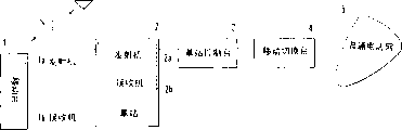
Fig. 1 is the structural representation according to the mobile communcations system of the first embodiment of the present invention.In Fig. 1, mobile communcations system comprises travelling carriage 1, is used for carrying out with travelling carriage 1 base station 2 of wireless telecommunications, is used to control the base station control station 3 of base station 2, the mobile cut bank 4 that links to each other with base station control station 3, and the routine call network 5 that links to each other with mobile cut bank 4.
Travelling carriage 1 has transmitter 1a and receiver 1b, and base station 2 has transmitter 2a and receiver 2b.Travelling carriage 1 links to each other with base station 2 by wireless channel, and base station 2 links to each other with routine call net 5 with mobile cut bank 4 by base station control station 3.
Fig. 2 illustrates the schematic diagram of the transmitter 1a of the travelling carriage 1 shown in Fig. 1.The transmitter 2a that is noted that base station 2 has the identical structure shown in Fig. 2.
As shown in Figure 2, transmitter 1a comprises microphone (MIC) 11; The CODEC part 12 of output of MIC11 is used to encode; Be used to modulate the modulator 13 and 14 of the output of CODEC part 12; Be used for exporting to modulator 13 and 14 respectively extended code/carrier wave the maker 15 and 16 of extended codes and carrier wave; Power setting device 17 and 18 is used for being provided with respectively the power of the output of modulator 13 and 14; Power setting controller 19 is used for power controlling part 17 and 18 is set; Synthesizer 20 is used for the output of synthetic power setting part 17 and 18; Amplifier (AMP) 21, the output that is used to amplify synthesizer 20, and the antenna 22 that links to each other with AMP21.
Fig. 3 illustrates the CODEC part 12 shown in Fig. 2.As shown in Figure 3, CODEC part 12 is made of the processing section 12b that A/D (mould/number) transducer 12a reaches the distribution that links to each other with A/D converter 12a.A/D converter will be imported analog signal conversion to be digital signal and it is outputed to the processing section 12b of distribution.The processing section 12b that distributes will be separated into important also exporting with non-important signal from the digital signal of A/D converter 12a.
The processing section 12b that distributes is separated into important and non-important signal according to the CODEC method with digital signal.For example, for the signal of 8 pieces, above the allocation process part 12b output as 4 of signal of interest and as following 4 of non-signal of interest.Change kind of a mode, above the allocation process part 12b output 2 as signal of interest and below 6 as non-important signal.
The operation that below description is had the mobile communcations system of the structure in this.
In travelling carriage 1, the A/D converter 12a by CODEC part 12 is converted to digital signal from the voice signal of MIC11, and digital signal is separated into the important and non-important signal line output of going forward side by side by allocation process part 12b.
By using extended code and carrier wave to carry out band spectrum modulation by modulator 13 and 14 pairs of important and non-signal of interests from CODEC part 12 from extended code/carrier generator 15 and 16.Modulated important and non-important signal is input to power setting part 17 and 18 respectively, power setting part 17 and the 18 importance setting powers corresponding to modulated important and non-important signal.It is synthetic to be synthesized device 20 from the output of power setting part 17 and 18, amplified by AMP21, and from antenna 22 outputs.
Signal of interest is corresponding to the high position of power stage, sound-source signal or conductance filter (the air conduction filter) constant that obtained by the analyzing speech signal, but not the corresponding low level of signal of interest.
In the case, under the control of power setting controller 19, signal of interest is set to such energy level by power setting part 17, promptly be output as 1W from antenna, opposite, under the control of power setting controller 19, non-signal of interest is set to from antenna and is output as 0.5W by power setting part 18.Two signals are to be synthesized by synthesizer 20, so antenna 22 output 1.5W.
In first embodiment, the power of signal of interest and non-signal of interest was set to 1: 0.5 at the output ratio of antenna 22, and determined this ratio by the characteristic of CODEC part 12.That is, determine this ratio according to the CODEC method of CODEC part 12.Owing to known the characteristic of CODEC part 12 in advance, so the ratio of this decision is used as fixed value.
Fig. 4 shows the schematic diagram of the transmitter 1a of travelling carriage 1 according to a second embodiment of the present invention.Be noted that, the transmitter 2a of base station 2 have with Fig. 4 in identical structure.
As shown in Figure 4, except the structure shown in Fig. 2, transmitter 1a also comprises: a plurality of CODEC part 12-1 are to 12-2, be used to be chosen in the transducer (SW) 23 of the output of the MIC11 that switches between CODEC part 12-1 and the 12-2, be used to be chosen in transducer (SW) 24 and the program storage 25 that switch between modulator 13 and 14 from a pair of important and non-signal of interest of CODEC part 12-1 and 12-2.
Handover operation by power setting controller 19 control SW23 and 24.With represent identical part at the identical label shown in Fig. 2, omit description to it.
In Fig. 4, will control to optimal value from the distribution of the transmitted power of antenna 22 according to the characteristic of CODEC part 12-1 and 12-2.In the case, because the required power ratio between important information and non-important information is not to be constant, be stored in advance among the memory 19a of power setting controller 19 corresponding to the control information of CODEC part 12-1 and 12-2.
Realize control by execution the program in the program storage 25 of being stored in by power setting controller 19.For program storage 25, can use ROM (read-only memory), RAM (random access memory), storage card or similar device.
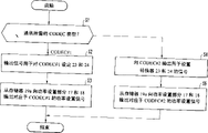
The power setting control of being undertaken by use power setting controller 19 is described below with reference to Fig. 5.
If power setting controller 19 determines that CODEC#2 (CODEC part 12-2) be the CODEC type required to communication, it is exported control signal to SW23 and SW24 and is used to select to the input of CODEC part 12-2 with from the output (step S4) of CODEC part 12-2.Power setting controller 19 is read power setting signal corresponding to CODEC part 12-2 from memory 19a, and the signal of reading is outputed to power setting part 17 and 18 (step S5).
In the case, when selecting the required CODEC type of communication, can set transmitted power according to the required error rate of selected CODEC type.In a second embodiment, can be removed for obtaining the required required a large amount of check digit of the error rate in the prior art, and only can obtain the required error rate by the check digit that adds minimum number.
Fig. 6 and Fig. 7 illustrate the base station 1 and 2 of a third embodiment in accordance with the invention.In the following description, travelling carriage 1 is as transmit leg, and base station 2 is as the recipient.
Travelling carriage 1 shown in Fig. 6 is except the structure shown in Fig. 2, also be included in and carry out the multiplexer 26 of 2-by a hybrid circuit being used to of constituting between antenna 22, transmitter 1a and the receiver 1b to the conversion of-4 lines, be used for by the receiver 27 of multiplexer 26 receptions from antenna 22 received signals, be used for the signal from receiver 27 outputs is carried out the speech processes part 28 of speech processes, and be used for the voice signal from 28 outputs of speech processes part is converted to a receiver 29 of audible signal.
As shown in Figure 7, base station 2 comprises antenna 30, at antenna 30, transmitter 2a, and carry out the multiplexer 31 of 2-by hybrid circuit being used to of constituting between the receiver 2b to the conversion of-4-line, be used for amplifying a radio frequency (RF) part 32 of the signal that receives from antenna 30 by transmitter 31, be used for the demodulator 33 and 34 of demodulation from the signal of RF part 32 outputs, controller 35, be used for according to the speech processes part 36 of exporting voice signal from the restituted signal of demodulator 33 and 34 outputs, and a transmitter 37, it is used for sending signal by multiplexer 31 to antenna output.
Note not shown demodulator circuit in Fig. 6, not shown modulation circuit in Fig. 7.
In the base station 2, demodulator 33 and 34 carries out error detection/correction to detecting the incoming level and the error rate respectively, and testing result is outputed to controller 35.If it is low that controller 35 is recognized from the error rate of the testing result of demodulator 33 and 34, its indication transmitter 37 is to travelling carriage 1 an output rising signals [UP (+)].If controller 35 is recognized error rate height, its indication transmitter 37 is to the signal [DOWN (-)] of a decline of travelling carriage output.
Then, transmitter 37 control information that is made of the upstream or downstream signal of self-controller 35 in the future sends to travelling carriage 1 by multiplexer 31 and antenna 30.
In travelling carriage 1, the control information that receives from base station 2 by antenna 22 and multiplexer 26 by receiver 27, and output to power setting controller 19.Power setting controller 19 power controlling on from the basis of the control information that is received by receiver 27 of base station 2 is provided with part 17 and 18.
According to the 3rd embodiment, the transmitted power setting of suitable each information of control in travelling carriage 1.In other words, the transmitted power of each information in the travelling carriage 1 is according to the transmitted power signalization from each information of base station 2 is set at optimal value.
In mobile communication, the transmit status of radio wave has changed greatly, and the power ratio between important information and non-important information does not need eternal constant.For this reason, in the 3rd embodiment, type predetermined electric power ratio according to the processing in CODEC part 12 can be set to original value, and is reset to optimal value from the transmitted power of travelling carriage 1 according to the transmission power determining signal to each information from base station 2.
This transmission power determining signal can be expression from the signal of the expression transmitted power of base station 2 or the signal of expression power rising/decline, and can set freely according to system.Similarly, travelling carriage can be determined transmitted power on the basis of the signal level that is received by base station 2.
The 3rd embodiment has described such situation, and wherein travelling carriage 1 is finished and sent and reception is finished in base station 2.Yet, even send and base station 1 is finished when receiving and also can be carried out same operation finishing when base station 2.At this moment, travelling carriage 1 is to the base station 2 report incoming level or the error rates, and base station 2 is according to its transmitted power of information setting from travelling carriage 1.
Has the transmission power control of the mobile communcations system of this kind structure below with reference to Fig. 8 and Fig. 9 description.
In the base station 2, symbol A represents the error rate of signal of interest; L11 and L12, the upper and lower bound of the prescribed limit of expression signal of interest; B represents the error rate of non-signal of interest; Reach the upper and lower bound that L21 and L22 represent the prescribed limit of non-signal of interest.
In travelling carriage 1, symbol P1 represents the transmission power value of current importance value; PA represents the performance number that basis is calculated from the control signal of base station 2; P2 represents the transmission power value of current non-importance value; PB represents the performance number that calculates according to from the control signal of base station 2.
More specifically, in Fig. 8, controller 35 detects from the error rate of the signal of interest of demodulator 33 (L12≤A≤L11) (step S11) in the scope of regulation whether.(A<L12), controller 35 indications reduce signal of interest transmitted powers (step S12) if the error rate A of signal of interest is less than the scope of stipulating.
(L12≤A≤L11), controller 35 indications keep the power (step S13) of signal of interest transmitted powers if the error rate of signal of interest falls into the scope of regulation at step S11.(A>L11), controller 35 indications increase the power (step S14) of signal of interest transmitted powers if the error rate A of signal of interest is greater than the scope of stipulating.
After the transmitted power of signal of interest was controlled, controller 35 checked whether the error rate B from the non-signal of interest of decoder 34 falls into scope (L22≤B≤L21) (the step S15) of regulation.(B<L22), controller 35 is indicated the non-signal of interest transmitted powers (step S16) that descend if the error rate B of non-signal of interest is less than the scope of stipulating.
(L22≤B≤L21), controller 35 indications keep non-signal of interest transmitted powers (step S17) if the error rate of non-signal of interest falls into the scope of regulation at step S15.If the error rate of non-signal of interest is greater than the scope (B is greater than L21) of regulation, controller 35 indications increase non-signal of interest transmitted power (step S18).Then, controller 35 controls transmitter 37 and will indicate the control information of the transmitted power of the important and non-signal of interest of control to be sent to travelling carriage 1 (step S19).
In the 3rd embodiment, travelling carriage 1 is sent the transmission power control indication with three kinds of patterns (increase power, reduce power, and remain unchanged).Alternative, also can use the absolute value of transmitted power to indicate transmission power control (promptly being set at xW or similar method).
On the other hand, travelling carriage 1 waits for that the control information from base station 2 is provided with initial control transmitted power.Promptly, in Fig. 9, when the power setting controller 19 of travelling carriage 1 from the base station 2 when receiving control information (step S21), the power control value that its detection is included in the signal of interest in the received control information whether be expression increase power, reduce power and remain unchanged in one (step S22).
If control information is represented the power of the power control value of signal of interest and descends that power setting controller 19 calculates PA=P1X1/2 (step S23).If control information represents to keep the power control value of signal of interest, power setting controller 19 calculates PA=P1X1 (step S24).Rise if the power of the power control value of signal of interest is represented in control information, power setting controller 19 calculates PA=P1X2 (step S25).
Then, power setting controller 19 detect the power control value that is included in the non-signal of interest in the control information whether be expression increase power, reduce power and remain unchanged in one (step S29).If control information is represented the power of the power control value of non-signal of interest and descends that power setting controller 19 calculates PB=P2X1/2 (step S30).If control information represents to keep the power control value of non-signal of interest, power setting controller 19 calculates PB=P2X1 (step S31).Rise if the power of the power control value of non-signal of interest is represented in control information, power setting controller 19 calculates PB=P2X2 (step S32).
Figure 10 illustrates the receiver 2b of the base station 2 of a fourth embodiment in accordance with the invention.Be noted that, the receiver 1b of travelling carriage 1 have with Figure 10 in identical structure.
The signal that is received by antenna 40 is divided into required frequency by RF part 41, and outputs to demodulator 42 and 43 and clock generator 44 and 45.Clock generator 44 and 45 detect the signal that receives by RF part 41 synchronously, and produce preset clock signal again, they are outputed to transducer 47 and 48.
Clock controller 46 is according to coming self-clock to send out the synchronous detection signal of device 44 and 45 to transducer 47 and 48 output switching signals.Then, be provided to demodulator 42 and 43 simultaneously from one in synchronous two clocks of the foundation of clock generator 44 and 45.If demodulator 42 can't be synchronous, it is according to the signal that clock signal demodulation that transducer 47 provides is separated by RF part 41 that passes through from clock generator 45.
In travelling carriage 1, the data of important information and synchronized with each other the sending of the data of non-important information.2 one sides in the base station, if in demodulator 42 and 43 one has set up synchronously, same in another demodulator also synchronous clock be used to stable synchronously.If two signals from the RF part are synthesized to extract a clock signal from this composite signal, this clock signal can be by more stable generation.
Figure 11 illustrates the schematic diagram of the transmitter 1a of travelling carriage 1 according to a fifth embodiment of the invention.
As shown in Figure 11, transmitter 1a comprises modulator 13 and 14; Extended code/carrier generator 15 and 16; Power setting part 17 and 18; Power setting controller 19; Synthesizer 20; Amplifier (AMP) 21; Antenna 22; Program storage 25; And signal type detector 51 and 52.
In having the transmitter 1a of this structure, input signal # 1 and #2 are used extended code and the carrier wave from extended code/carrier generator 15 and 16 to carry out the extended code modulation by modulator 13 and 14.After this, the power of input signal # 1 and #2 is set by power setting part 17 and 18 according to the control of power setting controller 19.Be synthesized device 20 from the output of power setting part 17 and 18 and synthesize, be exaggerated device 21 and amplify, and send from antenna 22.
The signal type of input signal # 1 and #2 (being speech data or pictorial data) is detected by signal type detection device 51 and 52 respectively.Signal type detection device 51 and 52 testing result are sent to power setting controller 19, and its power controlling on the basis of the testing result of signal type detection device 51 and 52 is provided with the power setting in part 17 and 18.
Below with reference to the flow chart shown in Figure 12 the transmitter 1a shown in Figure 11 is described.
When power setting controller 19 receives type from the input signal # 1 of signal type detection device 51 and 52 and #2, the signal type importance (step S41) in its decision communication.If to the required signal type of communication is signal type # 1, power setting controller 19 is read the power setting signal of respective signal type # 1 from memory 19a, and the signal of reading is outputed to power setting part 17 and 18 (step S42).
If the required signal type of communication is #2, power setting controller 19 is read power setting signal corresponding to signal type # 2 from power setting controller 19, and the signal of reading is outputed to power setting part 17 and 18 (step S43).
Therefore, when selecting the signal type of the required signal of communication, can set transmitted power according to the required error rate of selected signal type.In the 5th embodiment,, just can obtain the required error rate by adding minimum check digit in the prior art for the big check digit that obtains the required error rate and need can be saved.
Figure 13 illustrates the structural representation of mobile communcations system according to a sixth embodiment of the invention.As shown in Figure 13, mobile communcations system comprises: travelling carriage 1, base station 2-1 and 2-2, base station control station 3-1 and 3-2, mobile cut bank 4, and routine call network 5.Mobile cut bank 4 comprises transducer (SW# 1 and SW#2) 61 and 63, base station switching part 62, control channel controller 64 and control channel signals generator 65.
Travelling carriage 1 links to each other by radio wave with 2-2 with base station 2-1, and is connected to routine call network 5 by base stations control part 3-1 and 3-2 and mobile cut bank 4 from base station 2-1 and 2-2.Travelling carriage 1 can adopt any a kind of structure in the above embodiments 1 to 5.
Travelling carriage 1 synthesizes important and non-important signal or signal type # 1 and #2, and synthetic signal is sent to base station 2-1 and 2-2 as wireless signal.Based on receiving wireless signal from travelling carriage 1, base station 2-1 and 2-2 are sent to mobile cut bank 4 with received signal by base station control station 3-1 and 3-2.
In mobile cut bank 4, base station switching part 62 is selected by transducer 61 faultless signal from each frame (data block) of base station 2-1 and 2-2 input, and is voice signal with selected conversion of signals, and is sent to the routine call network by transducer 63.
In the case, even, also can use other faultless signal, so the error rate can be increased if having mistake from the signal of base station 2-1 and 2-2.If increased bit error rate can guarantee the error rate stipulated so then can realize normal speech communication.At this moment, base station switching part 62 is represented the signal of increased bit error rate to 64 outputs of control channel controller.
Figure 14 illustrates the base station 2-1 shown in Figure 13.Be noted that base station 2-2 has the identical structure among Figure 14.As shown in Figure 14, base station 2-1 or 2-2 comprise antenna 30, multiplexer 31, RF part 32, demodulator 33 and 34, controller 35, transmitter 37 and synthesizer 60.
The synthetic error rate the unit of a plurality of signals that controller 35 will receive from mobile cut bank 4 by control channel and from the error rate addition of demodulator 33 and 34, and control the transmitted power of the travelling carriage 1 in a plurality of signal elements.
Figure 15 shows the base station switching part 62 shown in Figure 13.As shown in Figure 15, base station switching part 62 comprises demultiplexer 62a and 62b, transducer (SW) 62c and 62d, speech processes part 62e and switch controller 62f.
Switch controller 62f determines whether the error condition signal exists mistake, thereby and control transformation device 62c and 62d select faultless signal.In the case, the independent a plurality of signals of control of switch controller 62f.
The error condition signal that switch controller 62f will obtain behind composite signal outputs to control channel controller 64.Control channel controller 64 is by control channel notice in the circuit pack of error condition signal among base station 2-1 and the 2-2 required.
As mentioned above, when using two base station 2-1 and 2-2 to carry out soft handover simultaneously (collisionless of the speech communication between the base station is switched), mobile cut bank 4 detectable errors and the further transmitted power that reduces from travelling carriage 1.
Because under the control of power setting controller 19, can the change transmitted power relevant with the reliability of the signal that will send, so can be according to required error rate setting transmitted power.Can be exempted for obtaining the required required big check digit of the error rate in the prior art, only just can be obtained the required error rate by adding minimum check digit.
Accordingly, transmitted power can be optimised.Owing to do not use extra transmitted power, can prevent to be subjected to the interference of another wireless channel, effectively frequency of utilization.Simultaneously can be according to the CODEC part 12-1 when switching CODEC part 12-1 and 12-2 and the property settings error rate of 12-2.
By according to transmitted power from the indicative of settings corresponding signal of recipient's power setting signal or power rising/decline, between communication period, can make error rate optimization, it can make communication always be in optimization.
The above embodiments not only are suitable for mobile communcations system but also the suitable analog signal of CDMA.These embodiment can be used to analog signal if the extended code of CDMA is used as frequency splitting channel.
In TDMA (time-division multiple access (TDMA)), embodiment can use the unit of bursting, and time slot is divided into sub-slots, or two or more time slot.
As mentioned above, according to the present invention,,, they are sent with different power when when transmitter will send a plurality of message segment at the wireless transmitting system that is used between transmitter and receiver, sending/receiving information by radio wave.This can guarantee to set the required error rate and effectively utilize frequency.
Claims (20)
1. wireless transmitting system, it is characterized in that by wireless channel transmitter (1a, 2a) and receiver (1b carries out the transmission/reception of information between 2b), and described transmitter comprises:
A plurality of power setting devices (17,18), a plurality of message segments that are used for being sent to described receiver are set to predetermined value; And
Dispensing device (21,22), a plurality of message segments of setting transmitted power that will have that are used for simultaneously send to described receiver.
2. system according to claim 1 is characterized in that described system also comprises synthesizer (20), is used for the multiplexed and synthetic a plurality of message segments of setting transmitted power that have; And
Described dispensing device will send to described receiver from the signal by multiplexed of described synthesizer output.
3. system according to claim 1 is characterized in that described transmitter also comprises separator (12), is used for the input information from an information source is separated into a plurality of message segments, and
Described power setting device is set transmitted power from a plurality of message segments of described separator respectively according to the reliability of information.
4. system according to claim 3 is characterized in that separator comprises the CODEC part, is used for according to the CODEC method input information being separated into signal of interest and non-signal of interest.
5. system according to claim 1 is characterized in that described transmitter also comprises a plurality of checkout gears (51,52), is used to detect the information type corresponding to the message segment of a plurality of input informations, and
Described power setting device is set the transmitted power of input information section on the basis of the testing result of described checkout gear.
6. system according to claim 1 is characterized in that described power setting device sets the transmitted power of a plurality of input information sections respectively on the basis of the reliability of input information section.
7. system according to claim 1 is characterized in that described receiver comprises information generation device (37), is used for generating control information on the basis of the information that receives from described receiver, and
Described power setting device is set the transmitted power of a plurality of message segments on from the basis of described receiver.
8. system according to claim 7 is characterized in that described receiver also comprises:
Separator (32), being used for the information separated that the type according to signal will receive from described transmitter is a plurality of message segments; And
A plurality of checkout gears (51,52) are used to detect the incoming level and the error rate from a plurality of message segments of described separator output, and the incoming level and the error rate are outputed to described dispensing device;
Described information generation device, it produces control signal on from the incoming level of described checkout gear and one basis in the error rate, and
Described power setting device is set the transmitted power of a plurality of message segments according in the incoming level and the error rate at least one respectively when described transmitter receives control signal from described receiver.
9. system according to claim 7 is characterized in that described power setting device is according to setting the transmitted power of a plurality of message segments from least one in the two of the controlling value of the control signal of the expression set value of the power of described receiver and indication increase/reduction transmitted power.
10. system according to claim 1, it is characterized in that from described transmitter synchronized with each other to a plurality of message segments that described receiver sends, and
Described receiver comprises:
A plurality of signal Synchronization devices (44,45) are used for the signal of other a plurality of message segments that send from described transmitter synchronously of branch; And
A plurality of demodulating equipments (42,43) are used for setting up when synchronous when a described synchronizer wherein and divide other demodulation a plurality of message segments according to shared synchronizing signal.
11. one kind by wireless channel transmitter (1a, 2a) and receiver (1b, 2b) between the method for transmission/reception information, it is characterized in that comprising following step:
Be used for a plurality of message segments that will be sent out variable respectively be set to predetermined value; And
The synchronous a plurality of message segments of setting transmitted power that will have send to described receiver.
12. method according to claim 11 is characterized in that variable setting step comprises following step:
To from the information separated of an information source a plurality of message segments;
Set the transmitted power of a plurality of separated information according to the reliability of information.
13. method according to claim 12 is characterized in that it is the step of signal of interest and non-signal of interest with information separated that separating step comprises according to the CODEC method.
14. method according to claim 11 is characterized in that method also comprises the step that detects the message segment type, and
Variable setting step also comprises the step according to the transmitted power of the type set information section of detected message segment.
15. method according to claim 11 is characterized in that variable setting step also comprises the step of setting the transmitted power of a plurality of message segments according to the reliability of information.
16. method according to claim 11 is characterized in that this method also comprises according to the information that receives from described transmitter to produce the step of control information in described receiver, reaches
Variable setting step comprises according to the step of setting the transmitted power of a plurality of message segments from the control information of described receiver.
17. method according to claim 16 is characterized in that also comprising following step:
Detect the incoming level of the information in the described receiver and the error rate and the incoming level and the error rate are outputed to described transmitter; And
Set the transmitted power of a plurality of message segments in the described transmitter according in the incoming level that is sent and the error rate at least one.
18. method according to claim 16 is characterized in that variable setting step comprises:
According to setting the transmitted power of a plurality of message segments from least one in the two of the controlling value of the control signal of the expression set value of the power of described receiver and indication increase/reduction transmitted power.
19. method according to claim 11 is characterized in that also comprising following step:
At described transmitter a plurality of message segments synchronized with each other are sent to receiver;
In described receiver, will divide other to carry out synchronously from a plurality of message segments of described transmitter emission; And
By synchronous message segment by the basis of synchronizing signal on a plurality of message segments of demodulation.
20. one kind be used for record by wireless channel transmitter (1a, 2a) and receiver (1b sends/receives the recording medium of the wireless transmission control program of information between 2b), it is characterized in that wherein comprising:
Be used for the variable respectively program that is set to predetermined value of a plurality of message segments that will be sent out; And
A plurality of message segments that will have the setting transmitted power simultaneously send to the program of described receiver.
Applications Claiming Priority (2)
| Application Number | Priority Date | Filing Date | Title |
|---|---|---|---|
| JP10137296A JPH11331131A (en) | 1998-05-20 | 1998-05-20 | System and method for radio transmission and recording medium with control program recorded therein |
| JP137296/98 | 1998-05-20 |
Publications (1)
| Publication Number | Publication Date |
|---|---|
| CN1236231A true CN1236231A (en) | 1999-11-24 |
Family
ID=15195377
Family Applications (1)
| Application Number | Title | Priority Date | Filing Date |
|---|---|---|---|
| CN99107445A Pending CN1236231A (en) | 1998-05-20 | 1999-05-19 | Radio transmission system and transmission method |
Country Status (5)
| Country | Link |
|---|---|
| EP (1) | EP0959581A2 (en) |
| JP (1) | JPH11331131A (en) |
| KR (1) | KR100325045B1 (en) |
| CN (1) | CN1236231A (en) |
| BR (1) | BR9902147A (en) |
Cited By (1)
| Publication number | Priority date | Publication date | Assignee | Title |
|---|---|---|---|---|
| US8286037B2 (en) | 2008-08-29 | 2012-10-09 | Realtek Semiconductor Corp. | Method and device for adjusting communications power |
Families Citing this family (15)
| Publication number | Priority date | Publication date | Assignee | Title |
|---|---|---|---|---|
| US6542481B2 (en) | 1998-06-01 | 2003-04-01 | Tantivy Communications, Inc. | Dynamic bandwidth allocation for multiple access communication using session queues |
| US6081536A (en) | 1997-06-20 | 2000-06-27 | Tantivy Communications, Inc. | Dynamic bandwidth allocation to transmit a wireless protocol across a code division multiple access (CDMA) radio link |
| US9525923B2 (en) | 1997-12-17 | 2016-12-20 | Intel Corporation | Multi-detection of heartbeat to reduce error probability |
| US7394791B2 (en) * | 1997-12-17 | 2008-07-01 | Interdigital Technology Corporation | Multi-detection of heartbeat to reduce error probability |
| US8134980B2 (en) | 1998-06-01 | 2012-03-13 | Ipr Licensing, Inc. | Transmittal of heartbeat signal at a lower level than heartbeat request |
| US7221664B2 (en) * | 1998-06-01 | 2007-05-22 | Interdigital Technology Corporation | Transmittal of heartbeat signal at a lower level than heartbeat request |
| JP4532635B2 (en) * | 1999-12-13 | 2010-08-25 | キヤノン株式会社 | Transmission power control system and communication station |
| JP3426200B2 (en) | 2000-08-02 | 2003-07-14 | 松下電器産業株式会社 | Communication terminal device and wireless communication method |
| JP2002199437A (en) * | 2000-12-25 | 2002-07-12 | Kyocera Corp | Base station unit |
| JP2002223448A (en) * | 2001-01-26 | 2002-08-09 | Matsushita Electric Ind Co Ltd | Image data transmitter, image data receiver, and image data communication system |
| KR100427190B1 (en) * | 2001-03-21 | 2004-04-17 | 주식회사 아이디폰 | Apparatus and method for wireless audio recording |
| ES2574242T3 (en) * | 2001-06-13 | 2016-06-16 | Intel Corporation | Mobile unit and procedure implemented in a mobile unit |
| EP2479905B1 (en) * | 2001-06-13 | 2017-03-15 | Intel Corporation | Method and apparatuses for transmittal of heartbeat signal at a lower level than heartbeat request |
| US7379434B2 (en) * | 2001-10-19 | 2008-05-27 | Koninklijke Philips Electronics N.V. | Radio communication system |
| JP5040751B2 (en) * | 2008-03-17 | 2012-10-03 | 富士通株式会社 | Signal transmission method and apparatus |
Family Cites Families (4)
| Publication number | Priority date | Publication date | Assignee | Title |
|---|---|---|---|---|
| JPH06268575A (en) * | 1993-03-12 | 1994-09-22 | Fujitsu Ltd | Channel access system for mobile communications system |
| US5732328A (en) * | 1995-04-25 | 1998-03-24 | Lucent Technologies Inc. | Method for power control in wireless networks for communicating multiple information classes |
| FI100157B (en) * | 1995-07-12 | 1997-09-30 | Nokia Mobile Phones Ltd | Circuit-switched carrier services with variable bit rates in TDMA-based cellular systems |
| JPH09307496A (en) * | 1996-05-16 | 1997-11-28 | Canon Inc | Radio communication equipment and radio communication system |
-
1998
- 1998-05-20 JP JP10137296A patent/JPH11331131A/en active Pending
-
1999
- 1999-05-18 KR KR1019990017719A patent/KR100325045B1/en not_active IP Right Cessation
- 1999-05-19 EP EP99109863A patent/EP0959581A2/en not_active Withdrawn
- 1999-05-19 CN CN99107445A patent/CN1236231A/en active Pending
- 1999-05-20 BR BR9902147-1A patent/BR9902147A/en not_active IP Right Cessation
Cited By (1)
| Publication number | Priority date | Publication date | Assignee | Title |
|---|---|---|---|---|
| US8286037B2 (en) | 2008-08-29 | 2012-10-09 | Realtek Semiconductor Corp. | Method and device for adjusting communications power |
Also Published As
| Publication number | Publication date |
|---|---|
| JPH11331131A (en) | 1999-11-30 |
| KR19990088348A (en) | 1999-12-27 |
| KR100325045B1 (en) | 2002-03-04 |
| EP0959581A2 (en) | 1999-11-24 |
| BR9902147A (en) | 2000-01-18 |
Similar Documents
| Publication | Publication Date | Title |
|---|---|---|
| CN1236231A (en) | Radio transmission system and transmission method | |
| CN1164133C (en) | CDMA communication system and its transmission power control method | |
| CN1080965C (en) | A CDMA communications method and system | |
| CN1172452C (en) | Method and apapratus for controlling transmission power while in soft handoff | |
| CN1160980C (en) | Device and method for providing selection transmit diversity in mobile communication system | |
| JP3320710B2 (en) | Spread spectrum communication apparatus and spread spectrum communication method | |
| CN1065995C (en) | Communication process in a radio telephone system | |
| CN1136742C (en) | Connection establishment method, subscriber terminal unit and radio system | |
| CN1157014C (en) | CDMA transmission system | |
| CN1046394C (en) | Radio telecommunication system | |
| CN1105475C (en) | CDMA mobile communication method, system, and mobile station equipment | |
| CN1149711C (en) | Adaptive array device | |
| US6104991A (en) | Speech encoding and decoding system which modifies encoding and decoding characteristics based on an audio signal | |
| CN1146148C (en) | Method of providing site selection diversity in mobile communication system | |
| CN1235440A (en) | Method and apparatus for radio communication | |
| CN1048472A (en) | The method of keeping mobile communication of mobile assist type | |
| CN1370382A (en) | Method and system for performing handoff in wireless communication system, such as hard handoff | |
| WO1998054850A3 (en) | Method and apparatus for wireless communication employing control for confidence metric bandwidth reduction | |
| CN101632240A (en) | The methods, devices and systems that are used for the phase difference adjustment of transmit diversity | |
| CN1135764C (en) | CDMA direct spread overlay system and method of operation | |
| CN1191045A (en) | Control message transmission in telecommunications system | |
| JP2892206B2 (en) | Audio data transmission device | |
| JP2001326603A (en) | Hands-off processing unit for communication system and its method | |
| WO2001003096A1 (en) | Method and apparatus for allocating channel element resources in communication systems | |
| CN1255790A (en) | Method and system for controlling searching device in code division multi-rute access system |
Legal Events
| Date | Code | Title | Description |
|---|---|---|---|
| C10 | Entry into substantive examination | ||
| SE01 | Entry into force of request for substantive examination | ||
| C06 | Publication | ||
| PB01 | Publication | ||
| C02 | Deemed withdrawal of patent application after publication (patent law 2001) | ||
| WD01 | Invention patent application deemed withdrawn after publication |