CN1233108C - Satellite communication transmission system and small global station - Google Patents
Satellite communication transmission system and small global station Download PDFInfo
- Publication number
- CN1233108C CN1233108C CNB021082405A CN02108240A CN1233108C CN 1233108 C CN1233108 C CN 1233108C CN B021082405 A CNB021082405 A CN B021082405A CN 02108240 A CN02108240 A CN 02108240A CN 1233108 C CN1233108 C CN 1233108C
- Authority
- CN
- China
- Prior art keywords
- frequency
- signal
- modulator
- station
- comparator
- Prior art date
- Legal status (The legal status is an assumption and is not a legal conclusion. Google has not performed a legal analysis and makes no representation as to the accuracy of the status listed.)
- Expired - Fee Related
Links
Images


Classifications
-
- H—ELECTRICITY
- H04—ELECTRIC COMMUNICATION TECHNIQUE
- H04B—TRANSMISSION
- H04B7/00—Radio transmission systems, i.e. using radiation field
- H04B7/14—Relay systems
- H04B7/15—Active relay systems
- H04B7/204—Multiple access
- H04B7/208—Frequency-division multiple access [FDMA]
-
- H—ELECTRICITY
- H04—ELECTRIC COMMUNICATION TECHNIQUE
- H04B—TRANSMISSION
- H04B7/00—Radio transmission systems, i.e. using radiation field
- H04B7/14—Relay systems
- H04B7/15—Active relay systems
- H04B7/185—Space-based or airborne stations; Stations for satellite systems
- H04B7/18528—Satellite systems for providing two-way communications service to a network of fixed stations, i.e. fixed satellite service or very small aperture terminal [VSAT] system
Landscapes
- Engineering & Computer Science (AREA)
- Computer Networks & Wireless Communication (AREA)
- Signal Processing (AREA)
- Physics & Mathematics (AREA)
- Astronomy & Astrophysics (AREA)
- Aviation & Aerospace Engineering (AREA)
- General Physics & Mathematics (AREA)
- Radio Relay Systems (AREA)
- Transmitters (AREA)
- Mobile Radio Communication Systems (AREA)
Abstract
A satellite communication transmission control system includes one central station, a plurality of small aperture terminals, and one communication satellite serving as a repeater for the central and aperture terminals. This system performs communication via a frequency division multiple access communication channel. The central station includes a modulator for transmitting via a common channel a signal for controlling/monitoring the small aperture terminals on the basis of a stable clock signal. Each aperture terminal includes a modulator, transmission frequency converter, antenna/RF device, reception frequency converter, demodulator, and frequency comparator. The modulator modulates communication information. The transmission frequency converter frequency-converts a modulated wave from the modulator into a carrier signal (modulated carrier). The reception frequency converter frequency-converts the modulated carrier. The demodulator demodulates a signal received via the common channel and outputs a reception clock. The frequency comparator detects the frequency error of a local oscillator, and generates a control signal for stopping transmission of the modulated carrier until the frequency error falls within a preset tolerance range.
Description
Technical field
The present invention relates to digital satellite communication system, more particularly, the present invention relates to satellite communication transmission system and small global station (aperture terminal), this satellite communication transmission system uses a zone center and a plurality of small global station, and repeater is carried out fdma communication via satellite.
Background technology
In the digital satellite communication system of forming by a zone center and a plurality of earth station, a kind of well-known satellite communication method is arranged, this method repeater via satellite exchanges modulated carrier between zone center and a plurality of earth station or between a plurality of earth stations, thereby carries out frequency division multiple access (hereinafter referred to as FDMA) communication.
In the FDMA satellite communication system, the precision of modulated carrier centre frequency must be set enough highly, thereby can be to not exerting an influence along the adjacent modulated carrier of the frequency axis of satellite relay.In other words, zone center and earth station always are inhibited in and send unsettled signal in the modulated carrier of transmission.
When a plurality of modulated carrier A, B and C were addressed to satellite relay, shown in Figure 1A, the centre frequency with modulated carrier of degree of precision can not cause problem to occur.But, if the centre frequency of given modulated carrier have one very big when wrong, this modulated carrier will produce adjacent modulated carrier and disturb, and can seriously have influence on himself, shown in Figure 1B.
In traditional radio communication, a kind of known launch control system is arranged in transmitter, this system is used to prevent transmitter unlatching unstable transmission signals of T-time afterwards.
For example, authorized in Japan and to have disclosed a kind of transmitting set among the patent gazette No.60-056778, this transmitter comprises a timer (energising timer), it can only open the power supply of the circuit that is positioned at antenna one side according to certain time-delay, its objective is in order to prevent the local oscillation that during feeding back to antenna, is produced when the power-on and any mistake that causes from crystal oscillating circuit, after crystal oscillating circuit was opened, this transmitter began by antenna emission transmission signals.Disclosed a kind of emission output control system among the Japan Patent No.2944480, in this system, transmitter is made up of controller (CPU), hardware control and on-reset circuit (energising timer), during power supply opening, emission output is subjected to the control of hardware control, when controller (CPU) when being activated, emission output is controlled according to the incoming level information from corresponding receiver.
Disclosed a kind of transmitter that has the circuit that prevents that noise from generating among the Japanese unexamined patent publication No.64-001335, this circuit can detect the noise that produces the digital phase discriminator within the automatic phase controller (APC) of transmitter, and can be after stopping to produce noise with one period scheduled time of outlet side switch opens of transmitter, its objective is for when transmitter is opened, even when the voltage controlled oscillator (VCO) of the APC that contains reference frequency oscillator by one when activating based on the different frequency of the centre frequency of reference frequency oscillator, also do not produce noise at receiver side.Authorization patent gazette No.09-135178 has disclosed a kind of emission output control system in Japan, this system utilizes the output of an alarm detection circuit monitors from the phase detectors among the similar APC (phase discriminator), and the On/Off of control emission switch, this system also contains an on-reset circuit (energising timer), when opening power, this on-reset circuit (energising timer) can be forbidden the unlatching of launching, thereby has prevented in the emission output because the instability of alarm detection circuit is operated the fluctuation that causes.
As mentioned above, at repeater via satellite between a zone center and a plurality of earth station or in the digital satellite communication system of executive communication between a plurality of earth stations, each earth station or similar device can both utilize the FDMA method via satellite repeater come executive communication.Transmit must its frequency band can not be overlapped situation under be launched.Specifically, when power-on, must prevent the emission that instability transmits.
For example, the frequency band of Ku band often is used among a kind of satellite communication system, in this system, earth station with the uplink of satellite in formed super mo(u)ld bottom half earth station scope from 14.0GHz to 14.5GHz.The tranmitting frequency error of modulated carrier is 1ppm (=1 * 10
-6).This error in wide spread spectrum ADPCM voice communication digital communication by satellite, is the modulated carrier of 32kbps for modulation rate corresponding to 14KHz, and this error is can not be uncared-for.In this system, be about ± 0.1ppm or littler as the fair limit of the tranmitting frequency error of the permissible error of tranmitting frequency.
The tranmitting frequency precision of the modulating wave that earth station sent depends on the tranmitting frequency transducer (hereinafter referred to as U/C (frequency up-converter)) in the radiating portion.U/C contains a local oscillator, and it has determined the center tranmitting frequency of modulated carrier.
This local oscillator is formed by a synthesis type PLL circuit.One has tens MHz (for example: 10MHz) crystal oscillator of frequency is used as oscillation source.This frequency is used (for example, concerning the oscillation source of 10MHz, multiply by 1400 and will produce 14GHz) by frequency multiplication and by local oscillator.If this oscillation source has the error of 1ppm, then this error also can correspondingly be exaggerated, and also will occur the error of 1ppm in local oscillator.
The precision of oscillation source has determined the center tranmitting frequency of modulated carrier.Therefore, the crystal oscillator as oscillation source must keep very high precision.
Usually, the temperature compensating type crystal oscillator (below be also referred to as OCXO) that is called OCXO (insulating box control crystal oscillator) is used widely, and this crystal oscillator can keep very high precision.OCXO is a kind of by using heater to produce the constant-temperature crystal oscillator of heat, and it has the crystal oscillator or the crystal oscillating circuit that are closed in the insulating box, and can realize high frequency stability.In general, the precision of OCXO can remain on ± 0.005ppm is to the scope of ± 0.01ppm.
When OCXO was activated (circuit is energized), its frequency accuracy was low to moderate tens ppm, up to the inner heating of insulating box and to reach heat static with till obtaining a stable temperature.Under present case, be a few minutes the warm-up time before the frequency stabilization.
In other words, after power-on servicing, in frequency reached a few minutes before stable, OCXO can not be used as the oscillation source of the PLL circuit that constitutes local oscillator.Be launched during this period if transmit, interference then can occur adjacent carrier.
Fig. 2 has shown an example of the frequency of oscillation error of OCXO after the power-on servicing.Among Fig. 2, transverse axis has been represented institute's elapsed time behind the electric power starting, the longitudinal axis then represented and nominal frequency between deviation.For example, if a modulated carrier is issued under the situation of the error existence of 10ppm, then the centre frequency of modulated carrier will be offset the frequency of 140KHz in the bandwidth of 14GHz, and this carrier wave will disturb adjacent carrier wave.
Launch control system described in the above-mentioned list of references is reserved as the conventional art of the emission of invalid signals when preventing electric power starting.The transmitting set that is disclosed among the Japanese unexamined patent publication No.60-059778 has used an energising timer, and it only forbids transmitting in one period scheduled time behind electric power starting.Even oscillator can not reach stable state because of any fault, this control system also can begin to transmit after a scheduled time, so just may make and original frequency between frequency error very big.So this system can not be used in the FDMA emission control.The emission output control system that is disclosed among the Japan Patent No.2944480 has used the information from corresponding receiver.But this reception information only is used to incoming level with control emission output level.After the work of energising timer, and between the centre frequency of emission carrier wave much frequency errors are arranged, transmitting all can be output.For example, the oscillator that promptly is used in the decision tranmitting frequency breaks down and with improper hunting of frequency, transmits also can be exported with this improper frequency one period scheduled time after.So this control system can not be applied among the FDMA emission control.
The launch control system that is disclosed among Japanese unexamined patent publication No.64-001335 and the 09-135178 monitors the output (APC voltage) from a phase discriminator.Even when the frequency of reference frequency oscillator has very mistake (for example, and the error of tens ppm being arranged between assigned frequency), this frequency also can be confirmed as normally.This control system can be launched the carrier wave with big frequency error not as the people with being willing to.
In sum, in the digital satellite communication system that is constituted by zone center, a plurality of super mo(u)ld bottom half earth station and a communication satellite, when repeater via satellite between a zone center and a plurality of earth stations or when between a plurality of earth stations, carrying out FDMA and communicating by letter, prior art can not be applied to the emission control of the modulator of zone center.
By a wide available bandwidth is set, just can avoid the influence of the emission signal frequency error of each earth station in satellite relay.But, consider that from the service efficiency and the cost aspect of frequency this measure is no advantage.
Summary of the invention
The problem in the conventional art of The present invention be directed to is arisen at the historic moment, and its objective is provides satellite communication transmission system and the small global station that stops the emission of modulated carrier during a kind of energising that can play pendulum in the frequency of local oscillator.
To achieve these goals, according to a first aspect of the invention, a kind of satellite communication transmission system is provided, this system is by a zone center, a plurality of small global stations and the satellite as the repeater of zone center and earth station constitute, it can be via a fdma communication channel executive communication, wherein, above-mentioned zone center contains modulator, it can transmit to be used for controlling/monitor small global station according to the stable clock signal by common channel, and above-mentioned each earth station all contains: be used for the modulator modulated from the communication information of information source; The frequency of modulated wave that is used for the device of automodulation in the future converts the tranmitting frequency transducer of modulated carrier to; Antenna/RF the equipment that is used for switching signal between earth station and zone center; Be used for the modulating wave from zone center is carried out the receive frequency transducer of frequency inverted; Demodulator, it is used for the signal of the frequency inverted received signal that has received through public letter is carried out demodulation and exports receive clock; An and frequency comparator, it can be when power-on servicing, be used to as a reference from the clock signal of demodulator, the frequency error that is arranged on the local oscillator in the tranmitting frequency transducer is detected, and can produce control signal to stop the emission of modulated carrier, till frequency error drops within the default allowed band.
Defined small global station also contains a switch in first aspect of the present invention, it is arranged on output one side of modulator, this switch is kept disconnecting by the control signal from frequency comparator, till frequency error drops within the default error range.
Defined small global station also comprises in first aspect of the present invention: a frequency inverted frequency mixer, and it is set within the tranmitting frequency transducer, and its effect is with the output of modulator and the output multiplication of local oscillator; And a switch in the middle of the signal path between being inserted in the local signal from the local oscillator to the frequency mixer, this switch is kept disconnecting by the control signal from frequency comparator, till frequency error drops within the default error range.
Defined small global station also comprises in first aspect of the present invention: one arranges to be used for modulator local oscillator and that modulator uses is inserted into the switch of local signal in the middle of from the modulator local oscillator to the signal path the modulator, this switch is kept disconnecting by the control signal from frequency comparator, till frequency error drops within the default error range.
Defined frequency comparator comprises in first aspect of the present invention: the allowed band setup unit that is used for the setpoint frequency error range; Be used to set one and be appointed as a timer of opening the scheduled time in cycle by clock signal; Be used for opposite house and open the counter of counting from the output of local oscillator in the cycle; And be used for the count value and of counter is preset the comparator that allowed band compares.
Defined local oscillator contains synthesizer in first aspect of the present invention, and it utilizes a temperature compensating crystal oscillator as oscillation source, and can export after the output frequency multiplication with temperature compensating crystal oscillator.
To achieve these goals, according to a second aspect of the invention, a kind of small global station that uses in satellite communication transmission system is provided, it is subjected to the control/supervision based on the signal of the stable clock signal of the common channel that sends to satellite relay from zone center, and can pass through the executive communication of fdma communication channel, this small global station comprises: be used for the modulator modulated from the communication information of information source; Be used for to convert the tranmitting frequency transducer of modulated carrier to from the frequency of modulated wave of said modulator; Antenna/RF the equipment that is used for switching signal between above-mentioned earth station and zone center; Be used for the modulated carrier from zone center is carried out the receive frequency transducer of frequency inverted; Demodulator, it is used for the signal of the frequency inverted received signal that has received through common channel is carried out demodulation, and the output receive clock; And frequency comparator, it is when power-on servicing, be used to as a reference from the clock signal of above-mentioned demodulator, the frequency error that is arranged on the local oscillator in the tranmitting frequency transducer is detected, and produce control signal stopping the emission of modulated carrier, in frequency error drops to default allowed band till.
To achieve these goals, according to a third aspect of the present invention, a kind of satellite communication transmission system is provided, this system comprises a zone center, a plurality of small global stations and a satellite as the repeater of zone center and earth station, and via the executive communication of fdma communication channel, it is characterized in that, above-mentioned zone center comprises modulator, it transmits by common channel, being used for controlling/monitor small global station according to the stable clock signal, and above-mentioned each earth station all contains: be used for the modulator modulated from the communication information of information source; The frequency of modulated wave that is used for the device of automodulation in the future converts the tranmitting frequency transducer of modulated carrier to; Antenna/RF the equipment that is used for switching signal between earth station and zone center; Be used for the modulated carrier from zone center is carried out the receive frequency transducer of frequency inverted; Demodulator is used for being carried out demodulation by the received signal of frequency inverted through the signal that common channel receives, and the output receive clock; And frequency comparator, it is when power-on servicing, be used to as a reference from the clock signal of demodulator, the frequency error that is arranged on the insulating box control crystal oscillator in the tranmitting frequency transducer is detected, and generation control signal, to drop in the default allowed band at frequency error before, stop the emission of modulated carrier.
From above-mentioned several aspects as can be seen, according to the present invention, the emission of the unstable modulated carrier that causes owing to the local oscillator frequency variation after following power-on servicing closely can be stopped by small global station according to a stable clock signal, and this clock signal is from obtaining from the signal that zone center receives by control/supervision common channel.So need not widen the occupied bandwidth of the satellite relay that is used to export modulated carrier, and frequency band is effectively used.And and adjacent modulated carrier between interference also can be inhibited.
The present invention carries out between from the output of local oscillator and a stable reference clock relatively absolute, and the emission of control modulated carrier.After within frequency error drops to a predictive error scope, modulated carrier is launched immediately.Compare with the method for emission modulated carrier on one period scheduled time after timer is started working after power-on servicing, the present invention has reached following remarkable result.That is be that the emission of modulated carrier can be stopped under the situation of carrying out with improper frequency because of the fault of oscillator, not detecting the vibration that is used for definite output frequency.In addition, emission can be after output frequency returns to normal value and is performed.
Those of ordinary skill in the art by with reference to following detailed explanatory note and accompanying drawing will to address many purposes on of the present invention, feature and advantage have more deep understanding, in these accompanying drawings, provide the preferred embodiment that combines the principle of the invention with the form of illustrative example.
Description of drawings
Figure 1A and 1B have shown the example of the Frequency Distribution of modulated carrier in the FDMA system;
An example of the frequency of oscillation error of OCXO when Fig. 2 has shown power-on servicing;
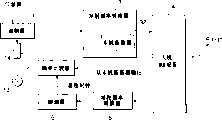
The schematic diagram of Fig. 3 A and 3B has demonstrated according to the general structure of digital satellite communication system of the present invention and communication function, and this system is made up of a HUB platform (zone center), a plurality of VSAT station and a communication satellite.
The block diagram of Fig. 4 has shown the structure according to the station of the VSAT among the satellite communication transmission system of the present invention;
The block diagram of Fig. 5 has shown the structure according to the HUB platform among the satellite communication transmission system of the present invention;
The block diagram of Fig. 6 has shown the detailed structure of local oscillator 32 in the VSAT station;
The block diagram of Fig. 7 has shown the detailed structure of VSAT station medium frequency comparator 7;
The block diagram of Fig. 8 has shown the another kind of structure according to the station of the VSAT among the satellite communication transmission system of the present invention;
The block diagram of Fig. 9 has shown the another kind of structure according to the station of the VSAT among the satellite communication transmission system of the present invention.
Embodiment
Below with reference to accompanying drawing to described in a preferred embodiment of the invention by a zone center (hereinafter referred to as the HUB platform), a plurality of super mo(u)ld bottom half earth station (VSAT; Hereinafter referred to as VSAT station) and the digital satellite communication system formed of the communication satellite (hereinafter referred to as SAT) of a repeater of standing as HUB and VSAT in the satellite communication transmission system that uses be elaborated.
The sketch of Fig. 3 A and 3B has demonstrated according to the general structure of digital satellite communication system of the present invention and communication function, and this system has used a HUB platform, a plurality of VSAT station and a SAT.As shown in Figure 3A, this digital satellite communication system is by: the HUB platform (zone center) that contain the SAT of a repeater, is connected with a central computer with information terminal and a plurality of and PC and the VSAT station (VSAT-A that links together such as the information terminal of phone, VSAT-B ...) form.FDMA (frequency division multiple access) communication be by between HUB platform and a plurality of VSAT station or the satellite relay of a plurality of VSAT between standing obtain carrying out.
This digital satellite communication system has used a common signal channel (hereinafter referred to as CSC) and has been in many data communication channels between each VSAT station, and the CSC channel is used as the common signal channel of standing from the VSAT of all participation satellite communications of HUB platform repeater control/supervisions via satellite.
Common channel (CSC channel) is such channel, and it adopts the way of timesharing to use a single-frequency to come executive communication between a plurality of.This channel usage TDM (time-sharing multiplex) method, TDMA (time division multiple access) method or time slot A LOHA method are come executive communication.
Shown in Fig. 3 B, the OB (departures circuit) at station and one stand to the IB (approach line) of HUB platform from VSAT and form common channel (CSC channel) from the HUB platform to VSAT by one.The timesharing control signal that contains a UW (unique word) frame structure utilizes different frequency bands to obtain exchange by OB and IB.
The VSAT station is subjected to the control/supervision of HUB platform by the CSC channel.Each VSAT station exchanges the modulated carrier between them mutually and carries out FDMA by utilization with the channel of the different pieces of information communication band of CSC channel different frequency and communicate by letter.Communication control process is as follows.
As shown in Figure 3A, the health examination control of the HUB platform OB that always utilizes the CSC channel by each VSAT station, the channel allocation control when the request that receives from the VSAT station and similar control (see among the figure arrow 1.-A and monitor 1.-B)/control that VSAT stands.For example, when the VSAT-A request of VSAT station communicated with VSAT station VSAT-B, VSAT station VSAT-A can ask to distribute by the IB of CSC channel the data communication channel (seeing that arrow 2.) of a HUB platform.Then, the HUB platform to VSAT station VSAT-A and VSAT-B distribute data communication channel (see among the figure arrow 1.-A and 1.-B).VSAT station VSAT-A and VSAT-B carry out two-way communication (seeing that arrow 3.) mutually by the different pieces of information communication channel of utilizing the HUB platform and being distributed.
In order reliably, stably to carry out this Control on Communication, the HUB platform contains an oscillator with high frequency accuracy, and this oscillator can produce a control signal transmit clock of giving the CSC channel to be launched.The HUB platform is carried out highly stable operation, any power supply trouble can not occur.
The block diagram of Fig. 4 has shown first structure example at employed VSAT station in the described according to one embodiment of present invention satellite communication transmission system.As shown in Figure 4, this VSAT station comprises: modulator 1, and it is used for the communication information from information source is modulated; Switch 2, it is used for the modulating wave of opening/closing from modulator 1; Tranmitting frequency transducer 3, it is used for the frequency inverted from the modulating wave of switch 2 is become FDMA carrier signal (modulated carrier); Antenna/RF equipment 4, it is made up of a RF circuit and a parabolic antenna, is used for and HUB platform switching signal; Receive frequency transducer 5, it is used for the modulated carrier from the HUB platform is carried out frequency inverted; Demodulator 6, it is used for the CSC channel signal of the frequency inverted received signal that has received is carried out demodulation and exports a receive clock; And frequency comparator 7.
A modulating wave is modulated and exported to 1 pair of communication information from the VSAT station of modulator.Switch 2 is by a control signal on/off from frequency comparator 7, and controlling the modulating wave that inputs to tranmitting frequency transducer 3.
The receive clock that 7 pairs of frequency comparators are demodulated from the CSC signal by demodulator 6 and the output frequency of local oscillator 32 compare.If error is within the predetermined frequency error range, then switch 2 is connected so that modulating wave passes through; Otherwise switch 2 will disconnect, and have a control signal output that is used to forbid that modulating wave passes through.
As improved embodiment, can be from local oscillator 32 outputs, and use from the independent output of OCXO shown in Figure 6 321 itself.
The block diagram of Fig. 5 has shown the structure of the HUB platform that uses in the described satellite communication transmission system of the embodiment of the invention.As shown in Figure 5, the HUB platform by modulator 9, high stable oscillator 8, tranmitting frequency transducer 10 and antenna/RF equipment 11 of being used to produce transmit clock forms.
Modulator 9 is one and is used for the transmit modulator that the similar signal at each VSAT station maybe can be controlled/be monitored to the CSC control signal channel.Control signal or similar signal are produced according to the transmit clock of the very high degree of precision frequency of oscillator 8.Tranmitting frequency transducer 10 has the function of frequency up-converter, and it can be increased to the modulation wave frequency such as control signal the carrier frequency for the treatment of the modulated carrier that sent by the HUB platform.Antenna/RF equipment 11 has an emission/receiving function with respect to each VSAT station.
The block diagram of Fig. 6 has demonstrated the detailed structure of the local oscillator 32 in the VSAT station.Local oscillator 32 contains a PLL circuit structure, and this circuit is by OCXO 321, be used for carry out the 1/m frequency divider (m: positive integer) 322 of frequency division from the output of OCXO 321, voltage controlled oscillator (VCO) 323, be used for the output of voltage controlled oscillator 323 is carried out the 1/n frequency divider (n: positive integer) 324 of frequency division, be used for the phase discriminator 325 that the output phase to above-mentioned these frequency dividers compares, be used for extracting the low pass filter of low frequency component from the phase error signal of phase discriminator 325, and the loop amplifier 327 that is used for above-mentioned low frequency signal is amplified is formed.
The block diagram of Fig. 7 has demonstrated the detailed structure of the frequency comparator 7 in the VSAT station.Frequency comparator 7 is made up of allowed band setup unit 71, comparator 72, timer 73, gate circuit 74 and counter 75.Allowed band setup unit 71 is setup units that are used for the setpoint frequency error range.Timer 73 is connected gate circuit 74 in one period scheduled time specified by receive clock.Counter 75 is counted the output of local oscillator 32 in the given time.Whether comparator 72 is in the allowed band setup unit 71 according to the count value of counter 75 is exported control signal within the predefined number range.
Below will be to describing according to the start-up operation when the radio station switches in the described satellite communication transmission system of present embodiment.
VSAT station shown in Fig. 4 is closed.The communication of the digital satellite communication system of repeater via satellite is in treats coldly the machine state.The switch 2 at VSAT station disconnects.In this state, the device at VSAT station is energized, and switch 2 responds power-on servicings and connected from off-state then.The local oscillator 32 that is made of the PLL circuit (as shown in Figure 6) that contains OCXO 321 also is switched on as the reference frequency oscillator, and the VSAT station is activated.
In the PLL circuit, voltage controlled oscillator 323 is subjected to the control of low pass filter 326 via the error signal of loop amplifier 327 output, with will be by predetermined the differing that characteristic was determined (differ and be generally 0) that is adjusted to by phase comparator 325 that differ between the output signal of the output of OCXO 321 being carried out output signal that the 1/m frequency division obtains and voltage controlled oscillator 323.Utilize this principle, frequency multiplication output (fvco=n/mfref) as local signal of PLL circuit output, this output are that multiplying each other obtains by the n/m (n/m>>1) with the vibration output frequency (fvco) of voltage controlled oscillator 323 and the reference oscillation frequency (fref) of OCXO 321.
The output frequency of OCXO 321 presents low frequency of oscillation precision in a period of time after following power-on servicing closely.Its frequency of oscillation stability arrives designated value needs one section preset time.Especially in OCXO, frequency accuracy is unstable always, is heated after power supply opening up to insulating box inside and reaches heat balance with till obtaining stable temperature.Therefore, frequency error is very big, and also very big by the error of the centre frequency that is used to determine tranmitting frequency in the formed local oscillator of PLL circuit that utilizes OCXO as the reference frequency oscillator.For example, during power-on servicing, the frequency accuracy of OCXO may drop to about tens ppm.During this period, the frequency of oscillation (fvco) of voltage controlled oscillator 323 outputs will become (n/m) * tens ppm.Therefore, the degree of frequency error increases.
Demodulator 6 in the VSAT station is configured to be used to receive the CSC channel that sends from the HUB platform usually.The CSC channel starts after receiving and operating in power-on servicing at once.As mentioned above, the CSC channel clock has the very oscillator appointment of high freuqency accuracy by one.The control signal of a high stability is launched, and the receive clock that demodulation is come out from control signal also has very high-precision frequency.
7 pairs of frequency comparators compare from the frequency of the local signal of local oscillator 32 and high accuracy receive clock (reference clock) from demodulator 6.Frequency comparator 7 detects frequency error, and to control signal of switch 2 outputs.More particularly, if frequency error is within the preset range, then frequency comparator 7 will be connected switch 2; Otherwise, then export a control signal with cut-off switch 2.
As mentioned above, the moment of the frequency error of OCXO 321 after power-on servicing is very big, and also very big through the frequency error of the local signal of frequency multiplication.Therefore, the comparative result of frequency comparator 7 will be in outside the error range.The switch 2 that is in off-state in power-on servicing is controlled with the comparative result according to frequency comparator 7 and keeps off-state.The modulating wave that leads to tranmitting frequency transducer 3 from modulator 1 is stopped.
Afterwards, if the frequency error of local signal descends and enters within the error range, then the comparative result of frequency comparator 7 will convert to switch 2 is connected.Then, the modulating wave from modulator 1 is input to tranmitting frequency transducer 3.Tranmitting frequency transducer 3 converts modulating wave to an intermediate frequency signal or radiofrequency signal.At last, the modulated carrier with high accuracy centre frequency is output to antenna/RF equipment 4, and is launched from antenna.
Even be energized at the VSAT station under the situation of actuator-activated and adding communication unconditionally, this structure and operation also can stop the emission of unstable modulated carrier.The beginning proper communication can be continued by the tdma communication channel in each VSAT station under each other without any situation about disturbing.
Below with reference to Fig. 7 the operation of frequency comparator 7 is described.Frequency comparator among Fig. 7 carries out work according to following principle,, in by the scheduled time that repetition rate determined of receive clock deviation between frequency is counted and determined to local signal that is.More particularly, timer 73 is exported the pulse signal of one period scheduled time by utilizing the high freuqency accuracy receive clock as the reference signal.Gate circuit 74 only is opened in this pulse period, and counter 75 in this pulse period to counting from the local signal of local oscillator 32.Comparator 72 checks out whether the count value of counter 75 falls into the scope of set point (for example, in allowed band setup unit 71 pre-set upper and lower bound) in this cycle.Then, control signal of comparator 72 outputs.Below introduce an example of these numerical value.
For example, when the predetermined period of pulse signal was 1 second, concerning the receive clock of 35kHz, timer 73 went out 35,000 receive clocks with number, and perhaps concerning the receive clock of 128kHz, timer 73 goes out 12,800 receive clocks with number.Timer 73 can be exported a pulse signal of 1 second.
In this 1 second, gate circuit 74 is opened, and is subjected to the counting of counter as measured signal from the output of local oscillator.If the nominal frequency of OCXO is 10MHz, then the count value of counter must reach 10,000,000 after 1 second.If count value is 10,000,001, then error is 1 * 10
-7
Allowed band pre-set in the frequency error that records and the allowed band setup unit 71 is compared.At last, frequency comparator produces an output.For example, (for example) ± α * 10 that configured in 72 pairs of frequency errors that record of comparator and the allowed band setup unit 71
-7Frequency error range compare.Comparator 72 checks whether measured frequency error falls within the setting range, and exports above-mentioned control signal with the output as frequency comparator.This frequency error detection is repeated to carry out after operating in power-on servicing.If the frequency of local oscillator is stablized gradually and fallen within this scope, then switch 2 will be connected to start predetermined firing operation.
Binary counter (pulsed counter and similar devices) is used as timer 73, and it is constituted as and can produces and export one and occupy 50% the frequency division output from the circulation of the receive clock in preset count device stage.Pulse signal of timer 73 outputs, this signal can make the frequency error detection operation be repeated to carry out.Time as the timer of reference signal can be by appropriate change.Postponing this time can produce higher frequency error measurement precision.
In the above-described embodiments, switch is arranged on the outlet side of modulator with as the device that is used to prevent unstable modulated carrier emission.But, can make various modifications to this device.Except switch being arranged in the outlet side of modulator, a device that can stop basically to antenna/RF equipment 4 output modulated carriers can be set also.
The block diagram of Fig. 8 and Fig. 9 has shown other structure example at the VSAT station of using in according to satellite communication transmission system of the present invention.Fig. 8 and Fig. 9 have demonstrated the another kind of concrete device that is used to stop the modulated carrier emission.In second kind of structure example shown in Figure 8, tranmitting frequency transducer 3 contains a frequency inverted frequency mixer 31, it is used for stopping modulated carrier from the device of tranmitting frequency transducer 3 to antenna/RF equipment 4 transmission with multiplying each other from the output of local oscillator 32 and modulating wave from modulator 1 as being used to.In addition, signal path, also inserted a switch 12 from local oscillator 32 to the local signal the frequency inverted frequency mixer 31.The on/off of local signal is by the output control from frequency comparator 7.In the third structure example shown in Figure 9, switch 14 is arranged at the outlet side of modulator local oscillator 13 (it is set in the modulator 1 usually, is used for baseband communication information is modulated).Switch 14 is arranged to can be by from the output of frequency comparator 7 and oscillation signals according with intermediate frequency of on.
As the device that is used to stop the modulated carrier emission, a switch that is used for the on modulated carrier can be set between tranmitting frequency transducer 3 and the antenna/RF equipment 4.Certainly, also at least two this switch combinations can be got up use.In brief, any have the function that oneself can stop modulated carrier and all can be used as the device that stops modulated carrier emission.
In the FDMA method, according to the dwelling period of modulated carrier, can set the error range of broad, to be used for the bigger tolerance frequency error of centre frequency.The allowed band that sets in the frequency comparator can arbitrarily be provided with.Utilize this structure, just can change modulated carrier and be output the time before according to the tolerance frequency error of the centre frequency in the FDMA method.
Claims (13)
1. satellite communication transmission system, this system comprises a zone center, a plurality of small global station and the satellite as the repeater of zone center and earth station, and via the executive communication of fdma communication channel,
It is characterized in that above-mentioned zone center contains modulator, it transmits by common channel, being used for controlling/monitor small global station according to the stable clock signal, and
Above-mentioned each earth station all contains: be used for the modulator modulated from the communication information of information source; The frequency of modulated wave that is used for the device of automodulation in the future converts the tranmitting frequency transducer of modulated carrier to; Antenna/RF the equipment that is used for switching signal between earth station and zone center; Be used for the modulated carrier from zone center is carried out the receive frequency transducer of frequency inverted; Demodulator is used for being carried out demodulation by the received signal of frequency inverted through the signal that common channel receives, and the output receive clock; And frequency comparator, it is when power-on servicing, be used to as a reference from the clock signal of demodulator, the frequency error that is arranged on the local oscillator in the tranmitting frequency transducer is detected, and generation control signal, to drop in the default allowed band at frequency error before, stop the emission of modulated carrier.
2. the system as claimed in claim 1, it is characterized in that above-mentioned small global station also contains switch, it is arranged on the outlet side of modulator, this switch is kept disconnecting by the control signal from frequency comparator, till frequency error drops within the default error range.
3. the system as claimed in claim 1 is characterized in that, above-mentioned small global station also comprises: the frequency inverted frequency mixer, and it is set within the tranmitting frequency transducer, and its effect is with the output of modulator and the output multiplication of local oscillator; And the switch in the middle of the local signal signal path of an insertion from local oscillator to frequency mixer, this switch is kept disconnecting by the control signal from frequency comparator, till frequency error drops within the default error range.
4. the system as claimed in claim 1, it is characterized in that, above-mentioned small global station also comprises: the modulator local oscillator of arranging to be used for modulator, and the switch in the middle of the local signal signal path of insertion from the modulator local oscillator to modulator, this switch is kept disconnecting by the control signal from frequency comparator, till frequency error drops within the default error range.
5. the system as claimed in claim 1 is characterized in that the said frequencies comparator comprises: the allowed band setup unit that is used for the setpoint frequency error range; Be used to set by clock signal and be appointed as a timer of opening the scheduled time in cycle; Be used for opposite house and open the counter of counting from the output of local oscillator in the cycle; And be used for the comparator that count value and default allowed band to counter compare.
6. the system as claimed in claim 1 is characterized in that above-mentioned local oscillator contains synthesizer, and it utilizes temperature compensating crystal oscillator as oscillation source, and the output of the frequency multiplication of output temperature compensated crystal oscillator.
7. small global station that in satellite communication transmission system, uses, it is subjected to the control/supervision based on the signal of the stable clock signal of the common channel that sends to satellite relay from zone center, and can pass through the executive communication of fdma communication channel, this small global station comprises: be used for the modulator modulated from the communication information of information source; Be used for to convert the tranmitting frequency transducer of modulated carrier to from the frequency of modulated wave of said modulator; Antenna/RF the equipment that is used for switching signal between above-mentioned earth station and zone center; Be used for the modulated carrier from zone center is carried out the receive frequency transducer of frequency inverted; Demodulator, it is used for the signal of the frequency inverted received signal that has received through common channel is carried out demodulation, and the output receive clock; And frequency comparator, it is when power-on servicing, be used to as a reference from the clock signal of above-mentioned demodulator, the frequency error that is arranged on the local oscillator in the tranmitting frequency transducer is detected, and produce control signal stopping the emission of modulated carrier, in frequency error drops to default allowed band till.
8. small global station as claimed in claim 7, it is characterized in that, above-mentioned small global station also contains switch, it is arranged on output one side of said modulator, and this switch is by the control signal maintenance disconnection from the said frequencies comparator, till frequency error drops within the default error range.
9. small global station as claimed in claim 7, it is characterized in that, above-mentioned small global station also comprises: the frequency inverted frequency mixer, and it is set within the above-mentioned tranmitting frequency transducer, and its effect is with the output of said modulator and the output multiplication of above-mentioned local oscillator; And the switch in the middle of the signal path of the local signal of insertion from local oscillator to above-mentioned frequency mixer, this switch is kept disconnecting by the control signal from the said frequencies comparator, till frequency error drops within the default error range.
10. small global station as claimed in claim 7, it is characterized in that, above-mentioned small global station also comprises: the switch in the middle of the signal path of arranging to be used for the modulator local oscillator of said modulator use and to insert the local signal from the said modulator local oscillator to above-mentioned modulator, this switch is kept disconnecting by the control signal from the said frequencies comparator, till frequency error drops within the default error range.
11. small global station as claimed in claim 7 is characterized in that, the said frequencies comparator comprises: one is used for the allowed band setup unit of setpoint frequency error range; Be used to set one and be appointed as a timer of opening the scheduled time in cycle by clock signal; Be used for opposite house and open the counter of counting from the output of above-mentioned local oscillator in the cycle; And be used for the comparator that count value and default allowed band to counter compare.
12. small global station as claimed in claim 7 is characterized in that, above-mentioned local oscillator contains synthesizer, and it utilizes temperature compensating crystal oscillator as oscillation source, and can export the frequency multiplication output of said temperature compensated crystal oscillator.
13. a satellite communication transmission system, this system comprises a zone center, a plurality of small global station and the satellite as the repeater of zone center and earth station, and via the executive communication of fdma communication channel,
It is characterized in that above-mentioned zone center comprises modulator, it transmits by common channel, being used for controlling/monitor small global station according to the stable clock signal, and
Above-mentioned each earth station all contains: be used for the modulator modulated from the communication information of information source; The frequency of modulated wave that is used for the device of automodulation in the future converts the tranmitting frequency transducer of modulated carrier to; Antenna/RF the equipment that is used for switching signal between earth station and zone center; Be used for the modulated carrier from zone center is carried out the receive frequency transducer of frequency inverted; Demodulator is used for being carried out demodulation by the received signal of frequency inverted through the signal that common channel receives, and the output receive clock; And frequency comparator, it is when power-on servicing, be used to as a reference from the clock signal of demodulator, the frequency error that is arranged on the insulating box control crystal oscillator in the tranmitting frequency transducer is detected, and generation control signal, to drop in the default allowed band at frequency error before, stop the emission of modulated carrier.
Applications Claiming Priority (2)
| Application Number | Priority Date | Filing Date | Title |
|---|---|---|---|
| JP093595/2001 | 2001-03-28 | ||
| JP2001093595A JP3599183B2 (en) | 2001-03-28 | 2001-03-28 | Satellite communication transmission control system and small earth station |
Publications (2)
| Publication Number | Publication Date |
|---|---|
| CN1378348A CN1378348A (en) | 2002-11-06 |
| CN1233108C true CN1233108C (en) | 2005-12-21 |
Family
ID=18947909
Family Applications (1)
| Application Number | Title | Priority Date | Filing Date |
|---|---|---|---|
| CNB021082405A Expired - Fee Related CN1233108C (en) | 2001-03-28 | 2002-03-28 | Satellite communication transmission system and small global station |
Country Status (6)
| Country | Link |
|---|---|
| US (1) | US6968162B2 (en) |
| EP (1) | EP1246375B1 (en) |
| JP (1) | JP3599183B2 (en) |
| CN (1) | CN1233108C (en) |
| DE (1) | DE60217004T2 (en) |
| NO (1) | NO325369B1 (en) |
Families Citing this family (13)
| Publication number | Priority date | Publication date | Assignee | Title |
|---|---|---|---|---|
| EP2472736A1 (en) * | 2003-05-23 | 2012-07-04 | Gilat Satellite Networks Ltd. | Frequency and timing synchronization and error correction in a satellite network |
| KR100693528B1 (en) * | 2004-10-29 | 2007-03-14 | 주식회사 팬택 | Wireless communication terminal for delaying power on |
| US7505738B2 (en) * | 2005-01-12 | 2009-03-17 | Uniden Corporation | Broadband receiver |
| WO2008068812A1 (en) * | 2006-11-30 | 2008-06-12 | Masprodenkoh Kabushikikaisha | Gap filler device |
| US8370606B2 (en) * | 2007-03-16 | 2013-02-05 | Atmel Corporation | Switching data pointers based on context |
| CN101335564B (en) * | 2008-05-16 | 2012-06-27 | 中国水利水电科学研究院 | TDMA method, server and system for VSAT station |
| EP2600529A3 (en) * | 2011-11-30 | 2016-02-24 | Sequans Communications Limited | Control circuitry |
| CN103281112B (en) * | 2013-04-23 | 2016-02-10 | 清华大学 | The Signal transmissions optimization method of FDMA digital channelizing satellite communication system |
| CN104393907B (en) * | 2014-11-21 | 2018-10-19 | 中国电子科技集团公司第三十八研究所 | A kind of satellite communication method |
| US10231201B2 (en) * | 2014-12-08 | 2019-03-12 | Nextnav, Llc | Systems and methods for assured time synchronization of an RF beacon |
| US10312996B2 (en) * | 2016-09-30 | 2019-06-04 | Hughes Network Systems, Llc | Systems and methods for using adaptive coding and modulation in a regenerative satellite communication system |
| CN107359883B (en) * | 2017-08-08 | 2022-11-18 | 歌尔股份有限公司 | Radio frequency transmitting and receiving device, transmitting and receiving system, unmanned aerial vehicle and unmanned aerial vehicle system |
| CN112994758B (en) * | 2021-02-05 | 2022-02-08 | 展讯通信(上海)有限公司 | Bluetooth signal receiver, control method, chip and terminal equipment |
Family Cites Families (21)
| Publication number | Priority date | Publication date | Assignee | Title |
|---|---|---|---|---|
| JPS6059778B2 (en) | 1980-10-30 | 1985-12-26 | 富士通株式会社 | wireless transmitter |
| JPS57174953A (en) | 1981-04-21 | 1982-10-27 | Nec Corp | Frequency measuring method |
| JPH0744485B2 (en) * | 1987-05-22 | 1995-05-15 | 三菱電機株式会社 | Car phone equipment |
| JPS641335A (en) | 1987-06-24 | 1989-01-05 | Nec Corp | Transmitter with noise preventing circuit |
| JPH07105822B2 (en) * | 1989-08-10 | 1995-11-13 | 三菱電機株式会社 | Automatic frequency controller |
| JPH04175013A (en) * | 1990-11-08 | 1992-06-23 | Toshiba Corp | Transmitter-receiver for satellite communication |
| JPH066275A (en) | 1992-03-13 | 1994-01-14 | Nippon Telegr & Teleph Corp <Ntt> | Diversity radio equipment |
| JPH06244783A (en) | 1993-02-19 | 1994-09-02 | N T T Idou Tsuushinmou Kk | Mobile body satellite communication system |
| US6047003A (en) * | 1993-12-27 | 2000-04-04 | Hyundai Electronics Industries Co., Inc. | Framing identification and timing signal extraction apparatus for very small aperture terminal system and method thereof |
| JP2707975B2 (en) | 1994-06-25 | 1998-02-04 | 日本電気株式会社 | Wireless communication device |
| US6366620B1 (en) * | 1994-12-13 | 2002-04-02 | Hughes Electronics Corporation | VSAT system |
| US5995812A (en) * | 1995-09-01 | 1999-11-30 | Hughes Electronics Corporation | VSAT frequency source using direct digital synthesizer |
| JP3428785B2 (en) | 1995-09-05 | 2003-07-22 | 松下電器産業株式会社 | Cellular cordless parent machine |
| JP2944480B2 (en) | 1995-09-25 | 1999-09-06 | 日本電気株式会社 | Transmission power control method |
| JPH09135178A (en) | 1995-11-07 | 1997-05-20 | Nec Corp | Transmission output control system |
| JP3179344B2 (en) | 1996-06-28 | 2001-06-25 | 静岡日本電気株式会社 | Automatic frequency correction method and communication control method in wireless communication terminal |
| JP3056197B1 (en) | 1999-02-17 | 2000-06-26 | 静岡日本電気株式会社 | Radio selective call receiver and local frequency generation method |
| JP2000295135A (en) | 1999-04-01 | 2000-10-20 | Nec Mobile Commun Ltd | Oscillation frequency control system for transmission/ reception device |
| JP2001016126A (en) | 1999-06-28 | 2001-01-19 | Hitachi Denshi Ltd | Radio equipment |
| JP3820063B2 (en) | 1999-07-16 | 2006-09-13 | 株式会社ケンウッド | Frequency control circuit |
| JP2001077670A (en) | 1999-08-31 | 2001-03-23 | Sanyo Electric Co Ltd | Frequency-correcting circuit and traveling object communications equipment |
-
2001
- 2001-03-28 JP JP2001093595A patent/JP3599183B2/en not_active Expired - Fee Related
-
2002
- 2002-03-25 NO NO20021484A patent/NO325369B1/en not_active IP Right Cessation
- 2002-03-27 US US10/106,501 patent/US6968162B2/en not_active Expired - Fee Related
- 2002-03-28 CN CNB021082405A patent/CN1233108C/en not_active Expired - Fee Related
- 2002-03-28 EP EP02007266A patent/EP1246375B1/en not_active Expired - Fee Related
- 2002-03-28 DE DE60217004T patent/DE60217004T2/en not_active Expired - Fee Related
Also Published As
| Publication number | Publication date |
|---|---|
| DE60217004D1 (en) | 2007-02-08 |
| EP1246375B1 (en) | 2006-12-27 |
| CN1378348A (en) | 2002-11-06 |
| NO20021484L (en) | 2002-09-30 |
| JP3599183B2 (en) | 2004-12-08 |
| US20020142718A1 (en) | 2002-10-03 |
| NO325369B1 (en) | 2008-04-14 |
| DE60217004T2 (en) | 2007-10-11 |
| JP2002290300A (en) | 2002-10-04 |
| NO20021484D0 (en) | 2002-03-25 |
| EP1246375A3 (en) | 2005-10-26 |
| US6968162B2 (en) | 2005-11-22 |
| EP1246375A2 (en) | 2002-10-02 |
Similar Documents
| Publication | Publication Date | Title |
|---|---|---|
| CN1233108C (en) | Satellite communication transmission system and small global station | |
| US11695529B2 (en) | Configuration of non-UE-specific search space for M-PDCCH | |
| US20220279502A1 (en) | Communication system | |
| US10517074B2 (en) | Methods for allocating data channel resources in a wireless communication system and apparatuses | |
| EP3621233B1 (en) | Methods for signal transmission and reception between terminal and base station in wireless communication system, and devices for supporting same | |
| CN105324946B (en) | The method of coverage area for enhancing user equipment and the device for utilizing this method | |
| JP3596618B2 (en) | Wireless telephone system for remote subscribers | |
| US11398882B2 (en) | Early termination of repeated transmissions between terminal and base station in wireless communication system | |
| EP0128210B1 (en) | Method and apparatus for synchronizing radio transmitters for synchronous radio transmission | |
| EP0553952A1 (en) | Satellite communications system with reservation protocol using at least three data channels | |
| CN102035566A (en) | Bidirectional wireless communication system, wireless communication apparatus, and bidirectional wireless communication method | |
| CN102726095B (en) | Machine-type communication method and system and small region search method and equipment | |
| WO1997017768A9 (en) | Method and apparatus for power control in a telephone system | |
| JPH04335724A (en) | Coherent light transmission reception method | |
| KR100513177B1 (en) | A frequency band conversion relay apparatus and method thereof same | |
| US7039062B1 (en) | System and method for pulsed cable telephony | |
| CN112640334A (en) | Calibration of synthesizer in radio receiver | |
| US20220132494A1 (en) | Uplink allocation in wireless communication systems | |
| WO2000057382A2 (en) | A wireles amr network | |
| US20230276388A1 (en) | Initial access and initial bandwidth part configuration for reduced capability user equipments | |
| RU2340103C2 (en) | Method of wireless communication with mobile objects and radiosystem for implementing method | |
| EP4342227A1 (en) | Opportunistic dual sim dual active operation in multi-subscriber identity module devices | |
| RU2075265C1 (en) | METHOD OF MULTI-STATION COMMUNICATION FOR LOW-ORBITAL SATELLITE SYSTEMS AND DEVICE FOR ITS IMPLEMENTATION |
Legal Events
| Date | Code | Title | Description |
|---|---|---|---|
| C10 | Entry into substantive examination | ||
| SE01 | Entry into force of request for substantive examination | ||
| C06 | Publication | ||
| PB01 | Publication | ||
| C14 | Grant of patent or utility model | ||
| GR01 | Patent grant | ||
| C17 | Cessation of patent right | ||
| CF01 | Termination of patent right due to non-payment of annual fee |
Granted publication date: 20051221 Termination date: 20100328 |