CN1232207C - Foldable cot and corner component for same - Google Patents
Foldable cot and corner component for same Download PDFInfo
- Publication number
- CN1232207C CN1232207C CN02150491.1A CN02150491A CN1232207C CN 1232207 C CN1232207 C CN 1232207C CN 02150491 A CN02150491 A CN 02150491A CN 1232207 C CN1232207 C CN 1232207C
- Authority
- CN
- China
- Prior art keywords
- cot
- recess
- bight
- leg
- stacks
- Prior art date
- Legal status (The legal status is an assumption and is not a legal conclusion. Google has not performed a legal analysis and makes no representation as to the accuracy of the status listed.)
- Expired - Fee Related
Links
Images


Classifications
-
- A—HUMAN NECESSITIES
- A47—FURNITURE; DOMESTIC ARTICLES OR APPLIANCES; COFFEE MILLS; SPICE MILLS; SUCTION CLEANERS IN GENERAL
- A47D—FURNITURE SPECIALLY ADAPTED FOR CHILDREN
- A47D7/00—Children's beds
-
- A—HUMAN NECESSITIES
- A47—FURNITURE; DOMESTIC ARTICLES OR APPLIANCES; COFFEE MILLS; SPICE MILLS; SUCTION CLEANERS IN GENERAL
- A47C—CHAIRS; SOFAS; BEDS
- A47C19/00—Bedsteads
- A47C19/20—Multi-stage bedsteads; e.g. bunk beds; Bedsteads stackable to multi-stage bedsteads
- A47C19/202—Stacking or nesting bedsteads
Abstract
The stackable cot comprises a sheet (5) stretched between elongated longitudinal and transverse elements connected to each other by corner elements (2) so as to form a generally rectangular frame. Each corner element (2) is on its lower surface provided with a foot (6), and on its upper surface provided with a vertical recess (7) aligned with the foot and constituting a recess for reception of a similar foot (6) of another cot (1) of the same type to be stacked on the cot. Each corner element (2) has an upper portion (10) and a lower portion (11) connected to each other. The recess (7) is formed in the upper portion (10) and it comprises a lateral opening in the form of a vertical slot opening outwardly and extending over substantially all the height of the recess (7) opening upwardly.
Description
Technical field
The present invention relates to a kind of cot and a kind of bight member that is used for to stack cot of stacking.
Background technology
Such cot that stacks is used in child-bearing center, day care service centre and kindergarten usually.They are usually included in the canvas that stretches by on the framework that is substantially rectangle that forms by the interconnective vertical and horizontal member of bight member.
Each bight member is provided with leg on its lower surface, and the surface is provided with recess thereon, and this recess aims at and be configured for holding the recess of the similar leg of another layer bed that will overlay on the ground floor bed with this leg.In known cot, leg is substantially cylinder form and these recesses also are substantially cylinder form, and has small gap so that make these cots to be stacked together mutually easily with respect to the profile of leg.
This structure is gratifying substantially, but there is certain danger in the hole that is formed by these recesses for child, insert because child understands the object that handle maybe can injure them.If hand keeps being stuck in the hole and baby's disequilibrium and falling, in fact just there is the danger of fracture.For this reason, preferably avoid on the member of bight, forming these holes.
Known have a kind of like this cot, and wherein the bight member has two parts, the upper and lower that promptly links together.In each bight member of this cot, the recess that is used for holding the leg that overlays the last cot on this cot is formed by the hollow feet of the bottom of upwards opening and the hole of aiming at notch seat on top basically.
This cot has above-mentioned shortcoming, and these bight members comprise the unfavorable junction of outside guiding on their all peripheries, because if this assembly surface is not aimed at fully, edge projection a little then must be arranged, so this can constitute danger.And, this existence of junction also can lure child that knife is injected wherein and when being at play grievous injury themselves.
Also have other known cot, wherein the bight member comprises quite simple shoulder on their outer surface, and the leg of cot adjacency when stacking is pressed against on this shoulder.In this case, these legs stack Shi Buhui at cot and block motionless individually.Because this fact that the member of their frameworks by forming cot links together is so they are actually jammed together.
The shortcoming of this cot is, folding corner region has hole or or even is formed on elongated hole between metallic plate and the bight member.Since above-mentioned same, so this also will be avoided.
Summary of the invention
The object of the present invention is to provide a kind of cot and bight member, they overcome existing cot shortcoming and since need not for parts carry out any machined and for assembling without any metal insert, so can reduce production costs.The present invention can also simplify the assembling of the member of cot.
The invention provides a kind of cot that stacks for this reason, it is included in the canvas that stretches by between the interconnective elongated vertical and horizontal member of bight member, each bight member be provided with two be used to hold with fixing described vertical and horizontal member to form the lateral aperture of the framework that is substantially rectangle together, each bight member is provided with leg on its lower surface, and the surface is provided with vertical recesses thereon, the recess of the similar leg of the cot that will overlay another same type on the described cot is aimed at and be configured for holding to this recess and described leg, each bight member has interconnective upper and lower, it is characterized in that the described recess that is used for holding leg is formed on described top and it and comprises lateral opening with the vertical slot form of outwards opening and extending on all height basically of the described recess of upwards opening.
According to another feature of the present invention:
The width of-described lateral opening is such, and it is motionless that the leg of last cot will keep in described recess in the horizontal, and can outwards not move;
-described top and described bottom are at interconnective two discrete items of the assembly process of cot;
-described holding in the convex part that recess is located at described top, the female component shape acting in conjunction suitably of this convex part and described bottom, female component comprises and the corresponding lateral opening of the lateral opening of described recess;
-described leg is a hollow, and the described convex part on top is provided with the cross member that forms the bottom that upwards surrounds described leg when fitting together in described top and the bottom at its lower end;
-described top and described bottom are included in upper lip and the lower lips on the opposite flank that is arranged on canvas in the folding corner region respectively;
-upper lip comprise on its lower surface be used for the upper surface that is arranged on described lower lips on fixture jointly cooperate and fix the device of described canvas;
-upper lip tilts so that be formed for the fixture of described canvas with lower lips when first and second parts fit together towards lower lips;
-described top is included in the skirt section of extending on the opposite flank of described lateral opening of described recess so that constitute guider at the assembly process of two parts, and constitutes protective device when two parts fit together;
The described upper and lower of-described bight member is fixed with each other by the screw jockey;
-each leg comprises the hole that is used for fixing roller at its free end.
The present invention also provides a kind of bight member that is used for stacking cot for this reason, it is comprising leg and is including vertical recesses on the surface thereon on its lower surface, the recess of the similar leg of another identical bight member is aimed at and be configured for holding to this recess and described leg, and two lateral apertures, be used for holding portraitlandscape member with elongate to form framework, described bight member has interconnective upper and lower, it is characterized in that, described recess is formed in the described top, and it comprises outwards to open and by upwards open the lateral opening of the vertical slot form of extending on all height basically of described recess.
According to another feature of the present invention:
-described recess is formed in the convex part on described top, and the female component shape of this convex part and described bottom acts synergistically suitably, and described female component comprises and the corresponding lateral opening of the lateral opening of described recess.
Brief description of drawings
From the explanation of following non-limiting embodiment of the present invention and with reference to accompanying drawing, will understand other features and advantages of the present invention more, wherein:
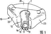
Fig. 1 is the front perspective view according to the top of bight of the present invention member;
Fig. 2 is the rearview on the top of Fig. 1;
Fig. 3 is the front perspective view according to the bottom of bight of the present invention member;
Fig. 4 is the rearview of the bottom of Fig. 1;
Fig. 5 is the front perspective view according to bight of the present invention member;
Fig. 6 is according to the rear view of bight of the present invention member after top and the bottom are fitted together;
Fig. 7 is the perspective schematic view according to the assembling of cot of the present invention;
Fig. 8 is the perspective view of the cot after assembling according to the present invention;
Fig. 9 has stacked several the incomplete perspective views according to cot of the present invention, and wherein nethermost cot is provided with roller.
Detailed description of preferred embodiments
In these figure, element identical or that be equal to will use identical Reference numeral.
Cot 1 is supporting the bight member 2 that links to each other by the vertical and horizontal member 3,4 that is made of metal tube usually.These members form a kind of framework that is substantially rectangle together, as will be in the back with reference to Fig. 7 described canvas 5 on this framework, stretch.
Therefore this cot is provided with four bight members 2.Each bight member includes leg 6 on its lower surface, and includes aim at this leg vertical on the surface thereon and hold recess 7, so that hold the leg of the respective shapes of the similar cot on the cot that will overlay and then in its lower section.
And each bight member 2 comprises that two are used for the lateral aperture 8,9 installing and fix, and these holes are used for holding respectively an end of longitudinal member 3 and an end of cross member 4.These accommodation holes 8,9 extend in horizontal plane basically mutual vertically.
According to the present invention, the bight member comprises top 10 and bottom 11.Top 10 and bottom 11 can and have in the overall appearance shown in Fig. 5 for a kind of monomer spare, perhaps also can be at least two independent and separated components, and they interconnect at the assembly process of cot, and are described in detail as the back.With this embodiment be that parts or two parts are irrelevant, hold recess 7 and be formed in the top 10 and comprise lateral opening with the form of the vertical slot 12 outwards opened and on all height basically of the recess of upwards opening 7, extend.
The width of lateral opening 12 is such, and the leg of last cot will keep laterally motionless and can outwards not move in recess 7.Recess 7 is cylinder form and by also making for columniform main body 13 in the embodiment shown in these figure.This main body 13 constitutes convex parts (referring to Fig. 2), and these parts are used for recess 14 (referring to Fig. 3) synergy on the upper surface with the bottom that constitutes female component.This female component 14 matches in shape and convex part 13, and comprises the lateral opening 12 corresponding lateral openings 15 with top 10.These convexs and female component preferably have round-shaped here.
In an illustrated embodiment, leg 6 is hollow and convex part 13 top 10 is provided with the cross member 16 that forms the bottom at its lower end, and (referring to Fig. 5) upwards sealing leg 6 when top and the bottom are fitted together.
In the embodiment shown in these figure, the end of convex part 13 is provided with the projection 17 that cross section reduces, and this projection is contained in when fitting together two top and the bottom in the recess 18 of lower end of female component 14.
This projection 17 preferably is provided with longitudinal rib 19 on the surface thereon, and the wall acting in conjunction of these ribs and recess 18 is so that fix this projection.
The top and the bottom 10,11 of bight member 2 comprise upper lip 20 and the lower lips 21 on the opposite face that is used for being arranged on the canvas 5 in the folding corner region 22 (seeing Fig. 8 and Fig. 9) respectively.The fixture that is used for canvas is formed on the lower surface of upper lip 20 and the upper surface of lower lips 21.These fixtures preferably are made of lip oneself and for obtaining improved grasp, upper lip 20 tilts towards lower lips 21, thereby these lips form a clip.
According to another modification (not shown), these fixtures that are used for canvas 5 are made of the flange on the upper surface that is arranged on lower lips 21, and with the lower surface that is located at upper lip 20 on recess synergy, perhaps vice versa.
Preferably, top 10 also is included in the skirt section 23 of extending on the opposite flank of lateral opening 12 of recess 7.This skirt section is injected by the convex component 13 on top at the assembly process of two parts 10,11 of bight member 2 to slide on the outer surface of bottom 11 in the female member 14 of bottoms 11 and is constituted guider.When top and the bottom 10,11 fitted together, the skirt section also was hidden in protective device between these two parts as will connect the plane when the bight member is made of two parts as shown in Figure 6.
For the fixing vertical and horizontal member 3,4 of cot framework, be used for holding and each hole 8,9 of fixing by the upper surface that is located at bottom 11 and be arranged to form (referring to Fig. 6) facing to the similar corresponding recesses 8B in the lower surface that is located at top 10, groove 8A, the 9A of 9B.
For make at the cot assembly process vertical and horizontal member holding with fixing hole 8,9 in motionless, many transverse bolt 24,25 is extended from groove 8A, 8B and 9A, 9B respectively.The pin of every pair of pin 24,25 passes the relative fixed hole 26 that is located in the vertical and horizontal member.The pin of every pair of pin 24,25 is arranged in the face of concerning that the pin of bottom is opened thus so that making hold-down screw 27 to insert passes fixing hole 28 downwards.
The leg 6 of bight member 2 preferably includes centre bore 29, and it is buckled in the fixing hole that is configured for roller 30 in this hole simply by the axle of roller.These rollers keep movable and can preferably be provided with brake.
In Fig. 7, schematically demonstrate the assembly program that comprises with the cot of the bight member of two component form.
At first cut out canvas 5 to obtain desired shape, this shape can obtain tubular edge 31 with welding or stitching by crooked.Each bight of canvas is cut into holds bight member 2.
Then, inject in the corresponding tubular edge 31 with these canvas 5 upsets and with vertical and horizontal member 3,4.Stretch out from the both sides of tubular edge so that make the pin 25 on top 10 can inject the hole 26 of vertical and horizontal member 3,4 end of each member, so these holes are plugged.Therefore be enclosed on the top 10 by the bottom 11 that will sell accordingly in 24 holes of injecting in the vertical and horizontal members 3,4 the bight member.Then hold-down screw 27 is inserted hole 28 in the lower surface that is passed in bottom 11 and bight member the latter and top 10 are linked together by being screwed in the pin 25.
Therefore the assembling of this cot can very simple and promptly realize, and does not need metal insert so that stretch canvas from a layback.In Fig. 8, demonstrate resulting cot.It very firmly and vertical and horizontal member 3,4 get lodged in the fixing hole 8,9 of bight member fully and can not deviate from.
At the bight member is in the embodiment of single parts, and the assembling of this cot is similar.Certainly, vertical and horizontal member 3,4 hold with fixing hole 8,9 in pin 25,26 be removed and replace by more common fixture, this fixture comprises quite simple hold-down screw, and this hold-down screw passes the transverse holes that communicates with the inside of accommodation hole 8,9 directly to be pressed against on the respective members 3,4 or to pass across passage in the wall that is located at the latter again.
Fig. 9 demonstrates be stacked together mutually several according to cot of the present invention.Because resulting piling up is perfect rigidity and if following cot is provided with roller 30 then moves easily, so no longer need special for stacking the annex of depositing of design.Be used for making it motionless brake if these rollers are provided with, then this piles up also and can use without difficulty.
Therefore just obtained a kind of cot as safe as a house that uses, it can not produce danger to still little child of age.
Certainly, shown in the present invention is not limited to and described embodiment, but all improvement in the scope that can also be included in those those of ordinary skills without departing from the scope of the invention.
Claims (22)
1. can stack cot, it is included in the canvas (5) that stretches by between interconnective elongated longitudinal member of bight member (2) (3) and the cross member (4), each bight member is provided with two holes, these two holes are used for holding and fix described longitudinal member (3) and cross member (4) to form a framework that is substantially rectangle together, each bight member (2) is being provided with leg (6) and is being provided with vertical recesses (7) on the surface thereon on its lower surface, this recess aims at and is configured for holding the recess of similar leg (6) of another sheet of canvas bed (1) of the same type that will overlay on the described cot with described leg, each bight member (2) has continuous top (10) and bottom (11), it is characterized in that, the described recess that is used for holding leg (6) is formed on described top (10), and this recess comprises the lateral opening (12) of the vertical slot form of outwards opening and extend on all height basically of the described recess of upwards opening (7).
2. the cot that stacks as claimed in claim 1 is characterized in that the width of described lateral opening (12) is such, and promptly the leg of Shang Mian cot (6) will keep in the horizontal being stuck in the described recess (7) and can not outwards move.
3. the cot that stacks as claimed in claim 1 or 2 is characterized in that, described top (10) and described bottom (11) are made by single parts.
4. the cot that stacks as claimed in claim 1 or 2 is characterized in that, described top (10) and described bottom (11) are two independent parts that the assembly process at cot is connected with each other.
5. the cot that stacks as claimed in claim 4, it is characterized in that, described recess (7) is located in the convex part (13) of described top (10), female component (14) shape of this convex part and described bottom (11) coacts suitably, and this female component comprises the corresponding lateral opening of lateral opening (12) (15) with described recess (7).
6. the cot that stacks as claimed in claim 5, wherein said leg (6) is a hollow, it is characterized in that, the described convex part (13) on top (10) is provided with the cross member (16) that forms the bottom at its lower end, and this bottom upwards surrounds described leg (6) in described top (10) and bottom (11) when fitting together.
7. as arbitrary described cot that stacks in the claim 2 to 6, it is characterized in that described top (10) and described bottom (11) comprise upper lip (20) and the lower lips (21) on two opposite flanks of the canvas (5) that is located in the folding corner region (22) respectively.
8. the cot that stacks as claimed in claim 7 is characterized in that, described upper lip (20) is comprising on its lower surface and is being located at fixture on the upper surface of described lower lips (21) and coacts and fix the device of described canvas (5).
9. the cot that stacks as claimed in claim 8, it is characterized in that described upper lip (20) tilts so that form the described fixture of described canvas (5) when fitting together in described top (10) and bottom (11) with described lower lips towards lower lips (21).
10. as arbitrary described cot that stacks among the claim 4-9; it is characterized in that; described top (10) is included in the skirt section (23) of extending on the opposite flank of described lateral opening (12) of described recess (7); thereby this skirt section constitutes guider in described top (10) and bottom (11) assembly process, and constitutes protective device when fitting together in described top (10) and bottom (11).
11., it is characterized in that the described top (10) of described bight member (2) and bottom (11) are fixed with each other by screw jockey (27) as arbitrary described cot that stacks among the claim 3-10.
12., it is characterized in that each leg comprises the fixing hole (29) that is used for roller (30) at its free end as arbitrary described cot that stacks in the claim of front.
13. be used for to stack the bight member of cot, this bight member includes leg (6) on its lower surface, and include the vertical recesses (7) of recess of the similar leg (6) of the bight member (2) of aiming at and be configured for holding another same type with described leg thereon on the surface, this bight member also comprise two be used to hold with elongate longitudinal member (3) and cross member (4) to form the lateral aperture of framework, described bight member has interconnective top (10) and bottom (11), it is characterized in that, described recess (7) is formed in the described top (10), and this recess comprises the lateral opening (12) of the vertical slot form of outwards opening and extend on all height basically of the described recess of upwards opening (7).
14. the bight member that is used for to stack cot as claimed in claim 13, it is characterized in that, the width of described lateral opening (12) is such, and promptly the leg (6) of another bight member (2) will be fixed in the horizontal in the described recess (7) and can not outwards move.
15., it is characterized in that described top (10) and described bottom (11) are made by single parts as claim 13 or the 14 described bight members that are used for to stack cot.
16., it is characterized in that described top (10) and described bottom (11) are two independent parts that the assembly process at cot is connected with each other as claim 13 or the 14 described bight members that are used for to stack cot.
17. as claim 13 or the 14 described bight members that are used for to stack cot, it is characterized in that, the described recess (7) that is used for holding is formed on the convex part (13) of described top (10), female component (14) shape of this convex part and described bottom (11) coacts suitably, and this female component comprises the corresponding lateral opening of lateral opening (12) (15) with described recess (7).
18. as arbitrary described bight member that is used for to stack cot in the claim 13 to 17, it is characterized in that described top (10) and described bottom (11) comprise upper lip (20) and the lower lips (21) on two opposite flanks that are located at canvas (5) respectively.
19. the bight member that is used for to stack cot as claimed in claim 18, it is characterized in that described upper lip (20) is comprising on its lower surface and is being located at fixture on the upper surface of described lower lips (21) and coacts and fix the device of described canvas (5).
20. the bight member that is used for to stack cot as claimed in claim 19, it is characterized in that described upper lip (20) tilts so that form the described fixture of described canvas (5) when fitting together in described top (10) and bottom (11) with described lower lips towards lower lips (21).
21. as arbitrary described bight member that is used for to stack cot among the claim 13-20; it is characterized in that; described top (10) is included in the skirt section (23) of extending on the opposite flank of described lateral opening (12) of described recess (7); thereby this skirt section constitutes guider in described top (10) and bottom (11) assembly process, and constitutes protective device when fitting together in described top (10) and bottom (11).
22., it is characterized in that each leg (6) comprises the fixing hole (29) that is used for roller (30) at its free end as arbitrary described bight member that is used for to stack cot among the claim 13-21.
Applications Claiming Priority (2)
| Application Number | Priority Date | Filing Date | Title |
|---|---|---|---|
| FR0114701 | 2001-11-14 | ||
| FR0114701A FR2832043B1 (en) | 2001-11-14 | 2001-11-14 | STACKABLE SLEEVE AND ANGLE MEMBER FOR SUCH A SLEEVE |
Publications (2)
| Publication Number | Publication Date |
|---|---|
| CN1418590A CN1418590A (en) | 2003-05-21 |
| CN1232207C true CN1232207C (en) | 2005-12-21 |
Family
ID=8869372
Family Applications (1)
| Application Number | Title | Priority Date | Filing Date |
|---|---|---|---|
| CN02150491.1A Expired - Fee Related CN1232207C (en) | 2001-11-14 | 2002-11-13 | Foldable cot and corner component for same |
Country Status (11)
| Country | Link |
|---|---|
| US (1) | US6701548B2 (en) |
| EP (1) | EP1312283B1 (en) |
| JP (1) | JP4095882B2 (en) |
| CN (1) | CN1232207C (en) |
| AT (1) | ATE274318T1 (en) |
| DE (1) | DE60201061T2 (en) |
| DK (1) | DK1312283T3 (en) |
| ES (1) | ES2227409T3 (en) |
| FR (1) | FR2832043B1 (en) |
| HK (1) | HK1054849A1 (en) |
| PT (1) | PT1312283E (en) |
Families Citing this family (28)
| Publication number | Priority date | Publication date | Assignee | Title |
|---|---|---|---|---|
| CA2413675C (en) * | 2002-12-06 | 2010-07-13 | Wellmaster Pipe And Supply Inc. | Unitized corner brace |
| CA2435453C (en) * | 2003-07-16 | 2008-08-05 | Robert James Hunter | Conversion kit for turning a cross-legged folding cot into a tiered cot |
| US7313835B1 (en) * | 2003-12-18 | 2008-01-01 | Elizabeth Hodges | Port-a-cot |
| US7086100B1 (en) * | 2005-05-11 | 2006-08-08 | Lo Feng-Jung | Joining assembly for child's bed |
| US7296310B2 (en) * | 2005-08-22 | 2007-11-20 | Milliken & Company | Adjustable mattress foundation |
| KR200452056Y1 (en) | 2008-12-08 | 2011-02-01 | 문성수 | Prefabricated bed |
| TW201036575A (en) * | 2009-04-03 | 2010-10-16 | Zhong-Ji Wei | Assembled bed |
| TW201110918A (en) * | 2009-09-25 | 2011-04-01 | Zhong-Ji Wei | Safety assembly bed |
| US8739333B2 (en) * | 2010-04-05 | 2014-06-03 | Central City Concern | Bedbug infestation-resistant bed |
| US8468713B2 (en) * | 2010-08-23 | 2013-06-25 | Karen Marie Evans | Contact lens case drying and storage rack assembly |
| US8919284B2 (en) * | 2012-04-20 | 2014-12-30 | Starmark Pet Products, Inc. | Animal bed |
| US9009887B2 (en) * | 2013-07-08 | 2015-04-21 | Delsun Co., Ltd. | Travel cot |
| US20150059089A1 (en) * | 2013-08-28 | 2015-03-05 | Matthew Falkiner | Portable Cot Apparatus for Hands and Legs Free Inflight Sleeping |
| USD731199S1 (en) * | 2013-12-03 | 2015-06-09 | Chih-Chi Wei | Children's cot without corner gaps |
| USD747116S1 (en) | 2014-07-21 | 2016-01-12 | Foundations Worldwide, Inc. | Cot |
| US9398815B2 (en) * | 2014-07-21 | 2016-07-26 | Foundations Worldwide, Inc. | Cot |
| US10045629B2 (en) | 2014-10-14 | 2018-08-14 | Wood Designs | Stackable leg |
| KR101598721B1 (en) * | 2014-12-19 | 2016-02-29 | 서기곤 | Height-adjustment and Height-adjustable camp bed |
| USD787873S1 (en) * | 2015-06-18 | 2017-05-30 | ECR4Kids, L.P. | Corner leg for cot |
| ES1168583Y (en) * | 2016-10-14 | 2017-01-24 | Rosa Salvador Jose Poveda | Bed or hammock |
| CA2960350A1 (en) * | 2017-03-09 | 2018-09-09 | BATRIK Medical Manufacturing Inc. | Step stool with anti-microbial protection |
| JP6766725B2 (en) * | 2017-03-27 | 2020-10-14 | 豊田合成株式会社 | Foam resin molded product |
| US10898006B2 (en) * | 2017-08-03 | 2021-01-26 | The Pet Cot Company | Cot and corner connector therefor |
| US10610723B2 (en) * | 2018-04-10 | 2020-04-07 | Balanced Body, Inc. | Ultra classic reformer apparatus |
| JP7197885B2 (en) * | 2018-06-11 | 2022-12-28 | グローバル電子株式会社 | motion detection bed |
| FR3091479B1 (en) | 2019-01-07 | 2020-12-11 | Wesco | bunk particularly stackable |
| US20210337975A1 (en) * | 2020-04-30 | 2021-11-04 | Holt Sales and Service, LLC | Modular, Compact, Stackable Beds And Associated Systems And Methods |
| KR102439068B1 (en) * | 2020-12-17 | 2022-09-01 | 주식회사 에코브 | Connecting apparatus for furniture frame and frame assembly using the same |
Family Cites Families (5)
| Publication number | Priority date | Publication date | Assignee | Title |
|---|---|---|---|---|
| US2924830A (en) * | 1953-07-02 | 1960-02-16 | Long Ruth Nash De | Nesting furniture structure |
| US2863568A (en) * | 1954-03-04 | 1958-12-09 | Paltier Corp | Bearing supports for pallet stacking |
| US4958390A (en) * | 1988-11-04 | 1990-09-25 | Holbrook-Patterson, Inc. | Rest cot assembly |
| US6513178B1 (en) * | 2000-05-15 | 2003-02-04 | Agi, Llc | Cot assembly |
| ATE333820T1 (en) * | 2000-12-27 | 2006-08-15 | Interdidak S L | LEG FOR A STACKABLE BED |
-
2001
- 2001-11-14 FR FR0114701A patent/FR2832043B1/en not_active Expired - Fee Related
-
2002
- 2002-11-06 ES ES02292757T patent/ES2227409T3/en not_active Expired - Lifetime
- 2002-11-06 AT AT02292757T patent/ATE274318T1/en active
- 2002-11-06 DK DK02292757T patent/DK1312283T3/en active
- 2002-11-06 DE DE60201061T patent/DE60201061T2/en not_active Expired - Lifetime
- 2002-11-06 EP EP02292757A patent/EP1312283B1/en not_active Expired - Lifetime
- 2002-11-06 PT PT02292757T patent/PT1312283E/en unknown
- 2002-11-13 CN CN02150491.1A patent/CN1232207C/en not_active Expired - Fee Related
- 2002-11-14 JP JP2002331004A patent/JP4095882B2/en not_active Expired - Fee Related
- 2002-11-14 US US10/293,352 patent/US6701548B2/en not_active Expired - Lifetime
-
2003
- 2003-10-13 HK HK03107312A patent/HK1054849A1/en not_active IP Right Cessation
Also Published As
| Publication number | Publication date |
|---|---|
| CN1418590A (en) | 2003-05-21 |
| DE60201061D1 (en) | 2004-09-30 |
| HK1054849A1 (en) | 2003-12-19 |
| US20030088914A1 (en) | 2003-05-15 |
| US6701548B2 (en) | 2004-03-09 |
| JP4095882B2 (en) | 2008-06-04 |
| FR2832043A1 (en) | 2003-05-16 |
| EP1312283B1 (en) | 2004-08-25 |
| DK1312283T3 (en) | 2005-02-28 |
| JP2003159157A (en) | 2003-06-03 |
| PT1312283E (en) | 2004-12-31 |
| EP1312283A1 (en) | 2003-05-21 |
| ES2227409T3 (en) | 2005-04-01 |
| DE60201061T2 (en) | 2005-09-29 |
| FR2832043B1 (en) | 2005-06-10 |
| ATE274318T1 (en) | 2004-09-15 |
Similar Documents
| Publication | Publication Date | Title |
|---|---|---|
| CN1232207C (en) | Foldable cot and corner component for same | |
| CN2436768Y (en) | Standard assembly board structure device | |
| US7568767B2 (en) | Snap-together patio bench | |
| US5762396A (en) | Stackable chair and associated stacking support assembly | |
| US20180027977A1 (en) | Mattress foundation kit | |
| US20110031798A1 (en) | Knock-down chair with intermediate support and compound leg | |
| CN1829459A (en) | Chair | |
| US11612252B1 (en) | Step stool and assembly methods | |
| ITMI20000553U1 (en) | RIGID AND STACKABLE CHAIR | |
| CN1449258A (en) | Chair base | |
| US20230042530A1 (en) | Headboard | |
| US20230240448A1 (en) | Bed ladder configured to be installed on bed frame for use | |
| CN2811175Y (en) | Polyethylene terephthalate bottle connector | |
| CN105849424B (en) | Assembly type block is constructed and latch-release part | |
| CN1901825A (en) | Side rail end connection system for bed frame | |
| CN1671318A (en) | Safety fence for infant | |
| US20030155565A1 (en) | Plastic fencing simulative of wrought iron | |
| KR101986069B1 (en) | Assembly type bed | |
| US20030201661A1 (en) | Ganging device for stackbar of stackable chair | |
| US7331072B2 (en) | Convertible bed having components serving multiple functions | |
| CN205827540U (en) | A kind of combined intelligent express delivery cabinet tool | |
| CN1838901A (en) | Combined component | |
| KR200438516Y1 (en) | Table that can regulate height | |
| CN1084042A (en) | Column and carrier support means with coupling member | |
| US20120013230A1 (en) | Collapsible furniture jointing system |
Legal Events
| Date | Code | Title | Description |
|---|---|---|---|
| C06 | Publication | ||
| PB01 | Publication | ||
| C10 | Entry into substantive examination | ||
| SE01 | Entry into force of request for substantive examination | ||
| C14 | Grant of patent or utility model | ||
| GR01 | Patent grant | ||
| CF01 | Termination of patent right due to non-payment of annual fee | ||
| CF01 | Termination of patent right due to non-payment of annual fee |
Granted publication date: 20051221 Termination date: 20181113 |