CN1228064A - Method and apparatus for treating wastewater - Google Patents
Method and apparatus for treating wastewater Download PDFInfo
- Publication number
- CN1228064A CN1228064A CN98800773A CN98800773A CN1228064A CN 1228064 A CN1228064 A CN 1228064A CN 98800773 A CN98800773 A CN 98800773A CN 98800773 A CN98800773 A CN 98800773A CN 1228064 A CN1228064 A CN 1228064A
- Authority
- CN
- China
- Prior art keywords
- treatment
- water
- weir
- mentioned
- water channel
- Prior art date
- Legal status (The legal status is an assumption and is not a legal conclusion. Google has not performed a legal analysis and makes no representation as to the accuracy of the status listed.)
- Granted
Links
Images


Classifications
-
- C—CHEMISTRY; METALLURGY
- C02—TREATMENT OF WATER, WASTE WATER, SEWAGE, OR SLUDGE
- C02F—TREATMENT OF WATER, WASTE WATER, SEWAGE, OR SLUDGE
- C02F3/00—Biological treatment of water, waste water, or sewage
- C02F3/02—Aerobic processes
- C02F3/12—Activated sludge processes
- C02F3/1236—Particular type of activated sludge installations
- C02F3/1257—Oxidation ditches
-
- C—CHEMISTRY; METALLURGY
- C02—TREATMENT OF WATER, WASTE WATER, SEWAGE, OR SLUDGE
- C02F—TREATMENT OF WATER, WASTE WATER, SEWAGE, OR SLUDGE
- C02F3/00—Biological treatment of water, waste water, or sewage
- C02F3/02—Aerobic processes
- C02F3/12—Activated sludge processes
- C02F3/14—Activated sludge processes using surface aeration
-
- B—PERFORMING OPERATIONS; TRANSPORTING
- B01—PHYSICAL OR CHEMICAL PROCESSES OR APPARATUS IN GENERAL
- B01F—MIXING, e.g. DISSOLVING, EMULSIFYING OR DISPERSING
- B01F23/00—Mixing according to the phases to be mixed, e.g. dispersing or emulsifying
- B01F23/20—Mixing gases with liquids
- B01F23/23—Mixing gases with liquids by introducing gases into liquid media, e.g. for producing aerated liquids
- B01F23/234—Surface aerating
- B01F23/2341—Surface aerating by cascading, spraying or projecting a liquid into a gaseous atmosphere
- B01F23/23411—Surface aerating by cascading, spraying or projecting a liquid into a gaseous atmosphere by cascading the liquid
-
- C—CHEMISTRY; METALLURGY
- C02—TREATMENT OF WATER, WASTE WATER, SEWAGE, OR SLUDGE
- C02F—TREATMENT OF WATER, WASTE WATER, SEWAGE, OR SLUDGE
- C02F3/00—Biological treatment of water, waste water, or sewage
- C02F3/02—Aerobic processes
- C02F3/12—Activated sludge processes
- C02F3/24—Activated sludge processes using free-fall aeration or spraying
-
- C—CHEMISTRY; METALLURGY
- C02—TREATMENT OF WATER, WASTE WATER, SEWAGE, OR SLUDGE
- C02F—TREATMENT OF WATER, WASTE WATER, SEWAGE, OR SLUDGE
- C02F3/00—Biological treatment of water, waste water, or sewage
- C02F3/30—Aerobic and anaerobic processes
- C02F3/301—Aerobic and anaerobic treatment in the same reactor
-
- Y—GENERAL TAGGING OF NEW TECHNOLOGICAL DEVELOPMENTS; GENERAL TAGGING OF CROSS-SECTIONAL TECHNOLOGIES SPANNING OVER SEVERAL SECTIONS OF THE IPC; TECHNICAL SUBJECTS COVERED BY FORMER USPC CROSS-REFERENCE ART COLLECTIONS [XRACs] AND DIGESTS
- Y02—TECHNOLOGIES OR APPLICATIONS FOR MITIGATION OR ADAPTATION AGAINST CLIMATE CHANGE
- Y02W—CLIMATE CHANGE MITIGATION TECHNOLOGIES RELATED TO WASTEWATER TREATMENT OR WASTE MANAGEMENT
- Y02W10/00—Technologies for wastewater treatment
- Y02W10/10—Biological treatment of water, waste water, or sewage
Landscapes
- Life Sciences & Earth Sciences (AREA)
- Chemical & Material Sciences (AREA)
- Biodiversity & Conservation Biology (AREA)
- Microbiology (AREA)
- Hydrology & Water Resources (AREA)
- Engineering & Computer Science (AREA)
- Environmental & Geological Engineering (AREA)
- Water Supply & Treatment (AREA)
- Organic Chemistry (AREA)
- Chemical Kinetics & Catalysis (AREA)
- Biological Treatment Of Waste Water (AREA)
- Purification Treatments By Anaerobic Or Anaerobic And Aerobic Bacteria Or Animals (AREA)
Abstract
Disclosed is a method and apparatus for treating secondarily wastewater by circulating primarily treated water T1 after removal of dust and inclusions contained in wastewater inside a water line for biological treating, wherein a weir (5) for forming a shooting flow energy absorber with an openable lower portion is provided inside circulating water lines (3a, 3b, 3c) in order to conduct any of an aerobic treating by only an overflow, an anaerobic treating by only a underground flow and aerobic and anaerobic treating by both of the overflow and the underground flow. In addition to the secondary treating using the shooting flow energy absorber, a higher-level treating is carried out by a biological treating using a plurality of elastic fiber shape contact materials 14 which are capable of shaking with a circulating water current and arranged separately along the water current direction inside circulating water lines (3e, 3e) in the apparatus for treating wastewater III, wherein said contact materials 14, acting as a carrier for biology, form a biological treating area 19 inside which secondary treated water T2 circulates to perform aerobic and anaerobic treating.
Description
The present invention relates to a kind of waste disposal plant that is applicable to middle and small scale sewage disposal, particularly sanitary sewage, following water treatment, water quality that this device is handled is good, and maintenance management is convenient, and is with low cost.
Always, " interval type activated sludge process " often adopted in the sewage disposal of middle and small scale.This method adopts single groove, carries out the gap aeration, precipitate simultaneously, release, but as carrying out stable treated to the processed water of water quality change, then operational management must be very careful, so very difficult aspect maintenance management.
Well-known " contact aeration process " in addition, this is that a kind of maintenance management is relatively easy to method, but this method also has problem, and it can not remove nitrogen component fully, and this must accomplish now.
Also has maintenance management in addition than being easier to, also can adapting to the what is called " oxidation canal method " that treatment capacity changes.This method is a kind of planktonic organism method, and water under it imports in circulating water flow circulates it, and aeration is carried out a biological disposal upon simultaneously.
Adopt this method, in order to carry out aeration and to flow, generally all adopt and mechanically make down water be able to mixing, aeration and mobile alr mode, but this mechanical aeration is because be surface aeration, so the depth of water can not be too dark, therefore area being set will do very greatly, blast the air blast mode of air as employing, in order to allow water flow, need very big power again so.
For aeration and the flow pattern that replaces this class machinery, the someone has proposed to adopt stagewise " landing current aeration method " (No. the 37195/1989th, Japanese patent laid-open publication gazette) has been set in the circulation water channel.
Adopt this method, can solve the problems referred to above of mechanical aeration method, but owing to adopt aeration and mobile source to be the so-called drop engineering of one, thereby can not carry out the required anaerobic treatment of nitrogen, phosphorus that becomes problem now for removing fully.Particularly, adopt this method can not efficiently denitrogenate indispensable anaerobism stir, therefore be difficult to sewage is carried out advanced treatment.
The objective of the invention is in order to solve the problem that above-mentioned prior art exists, particularly for a kind of novel waste disposal plant that is suitable for carrying out the middle and small scale sewage disposal is provided.That is to say that it is simple, compact to the invention provides a kind of equipment, low price, maintenance management is easy, the waste disposal plant that the water quality after the processing is good.
To achieve these goals, the present invention has adopted following way.
In claim 1, employing allows primary treatment water round-robin biological treatment secondary sewage treatment method in water channel of having removed contained rubbish, impurity etc. in the sewage, this sewage water treatment method, in above-mentioned water channel, be provided with down and can form the weir that jet subtracts the energy engineering by opening, can only carry out aerobic treatment, only carry out anaerobic treatment, also can both use overflow with undercurrent with overflow, use undercurrent again, carry out aerobic and anaerobic treatment.
Adopt this method, because can therefore can carry out effective sewage disposal to allowing the aerobic treatment of oxidation operation decomposition and the anaerobic treatment that denitrogenation is the master carry out freely selecting or making up according to the water quality of sewage such as following water.
In claim 2, the described sewage treatment of claim 1 of aerobic treatment and anaerobic treatment ratio can be freely adjusted in employing by the lower opening amount of regulating above-mentioned weir.
Adopt this method, adjust by lower opening amount the weir, not only can carry out freely selecting or making up to aerobic treatment and anaerobic treatment, but also can be to the ratio of overflow and undercurrent, the ratio that is aerobic treatment and anaerobic treatment is adjusted, and therefore can carry out more effective sewage disposal according to the water quality of sewage such as following water.
In claim 3, removed in the secondary sewage treatment device that the primary treatment water of contained rubbish, impurity etc. is carried out a biological disposal upon in the circulation water channel in the sewage allowing, be provided with and be discharged to the recycle pump of water channel top portion from the treating water that above-mentioned circulation water channel terminal part sucks, and be arranged at the circulation water channel, constitute, form the weir that jet subtracts the energy engineering midway by vertical wall and skew wall.
This drain treatment apparatus is by " moving up and down of above-mentioned weir main body self ", " between weir main body and water channel bottom, form peristome; be arranged at the moving up and down of flashboard of the vertical walls of the above-mentioned weir of fixed main body ", " between weir main body and water channel bottom, form peristome; be arranged at the rotation of open and close valve of the lower opening portion of the above-mentioned weir of fixed main body ", and any methods such as " constituting vertical wall the fascinating of above-mentioned weir main body " in the water channel direction, allow undercurrent recirculated water pass through from the peristome of below, weir, carry out anaerobic treatment, allow and form the jet landing from the recirculated water of weir top overflow, aeration, carry out aerobic treatment, can freely select both to carry out simultaneously, or carry out separately.
Adopt this method,, when the weir main body makes a decision at bottom land, just can only carry out treating water forms the jet landing from this weir top overflow aerobic treatment for weir main body self weir moving up and down.When the weir main body was fixed in the top position of water channel, no longer from the top overflow on this weir, recirculated water passed through from the below on this weir treating water, formed undercurrent, only carried out anaerobic treatment.When the weir main body was fixed in water channel above-below direction mid-way, treating water was from this weir top overflow, and recirculated water passes through from the below on this weir, forms undercurrent, can carry out aerobic treatment and anaerobic treatment simultaneously.
Like this, need only the water quality according to treating water, the position of regulating weir just can select to carry out aerobic treatment or anaerobic treatment arbitrarily, or both carries out simultaneously.
Form deposition opening portion as adopting between weir main body and water channel bottom, the method that allows the flashboard of the vertical walls that is arranged at fixed weir main body move up and down, then rise and select aerobic treatment or anaerobic treatment by this flashboard, or the effect of both adjustment component of carrying out simultaneously.
In other words,, change the opening flow and the weir upper end position of deposition opening portion, just can adjust the ratio of aerobic treatment and anaerobic treatment easily by suitably selecting the fixed position of this flashboard.
As adopting the deposition opening portion that forms between fixed weir main body and water channel bottom that the method for rotating open and close valve is set, then this open and close valve can change the opening amount of deposition opening portion, adjusts the ratio of aerobic treatment and anaerobic treatment easily.
In addition, the method as employing allows the vertical wall that constitutes above-mentioned weir main body fascinate with respect to skew wall is then risen by this vertical wall that can fascinate and selects aerobic treatment or anaerobic treatment, or the effect of both adjustment component of carrying out simultaneously.That is to say, change the opening amount of deposition opening portion, adjust the ratio of aerobic treatment and anaerobic treatment easily by the difference of the amount of fascinating.
In claim 4, adopt the waste disposal plant of claim 3 record, the angle that it is characterized in that being formed at the skew wall in main body downstream side, above-mentioned weir is variable.
Landing angle, the sinking speed of the recirculated water of square overflow from it can freely be adjusted in the weir of this effusive flow plane variable-angle, played adjust jet fall into water amount, be the effect of aeration rate.
In claim 5 and 6, be provided with the sinking weir in the circulation water channel bottom of claim 3,4 each weir body peripheral edge of putting down in writing respectively.
The effect on these sinking weirs is to make the circular treatment current by the below, weir become disorderly, thereby improves the effect that anaerobism stirs.
In claim 7 and 8, respectively with the relief outlet of the recycle pump of the waste disposal plant settings of claim 5,6 records towards deposition opening portion that the formation undercurrent that is formed at weir below is used.
The relief outlet of this recycle pump that is provided with towards deposition opening portion can positively play and allow recirculated water form the effect of undercurrent by deposition opening portion.
In claim 9, by throwing in the secondary treatment water of handling with the sewage water treatment method of claim 1 or claim 2 record, the waste disposal plant of advanced treatment is carried out in employing, a plurality of elastotic contact materials with the part that can shake because of circulating water flow are set in circulation water channel water (flow) direction compartment of terrain, these contact materials become biological carrier, form biological treatment zone, aeration is carried out in upstream at this biological treatment zone, allow the secondary treatment water cycle flow, carry out aerobic treatment and anaerobic treatment.
In claim 10, by throwing in the secondary treatment water of handling to any one waste disposal plant of being put down in writing of claim 8 with claim 3, the waste disposal plant of advanced treatment is carried out in employing, a plurality of elastotic contact materials with the part that can shake because of circulating water flow are set in circulation water channel water (flow) direction compartment of terrain, these contact materials become biological carrier, form biological treatment zone, allow the secondary treatment water cycle flow, carry out aerobic treatment and anaerobic treatment.
In the way of claim 9 or claim 10, can engineering carry out secondary treatment by subtracting with current, carry out advanced treatment, the treating water that can be purified more by the biological treatment of adopting contact material again.
In these ways, because adopted " elastotic contact material ", so contact material reduces the resistance to flow of circulating water flow with the part that can shake because of circulating water flow.Efficient as bio-carrier improves, and relatively firmly, can form good microbial film.
In claim 11, claim 12, the elastotic contact material that claim 9, claim 10 are put down in writing respectively adopts stranded fibrous bundle.
Adopt this way, stranded fibrous bundle shakes in water and scatters, and can enlarge biological attachment, form biomembranous surface-area.
To claim 16, the elastotic contact material that claim 9 to claim 12 is put down in writing respectively is made of carbonizedfibres in claim 13.
The biological excellent adsorption of carbonizedfibres is more effective as its effect of contact material.
The simple declaration of accompanying drawing
Fig. 1 be represent briefly before the waste disposal plant advanced treatment of the present invention once, the front view of first embodiment in secondary treatment stage.
Fig. 2 is the view along the X-X line direction of Fig. 1 of this embodiment, (a) the movable weir main body that is arranged at this device for the expression accompanying drawing when bottom land that makes a decision, (b) above-below direction that is fixed in groove for this weir main body of the expression accompanying drawing of mid-way situation roughly (c) is fixed in the accompanying drawing of the top position situation of groove for this weir main body of expression.
Fig. 3 be this weir of expression variation, along the view of the X-X line direction of Fig. 1, (a) the slide down dynamic formula flashboard of vertical wall segments that is arranged at the fixed weir upstream side for expression makes a decision in the accompanying drawing of bottom land situation, (b) for this flashboard is fixed in the top position, the accompanying drawing of formation deposition opening portion situation below the main body of weir.
Fig. 4 be this weir of expression another variation, along the view of the X-X line direction of Fig. 1, (a) open and close valve of lower opening portion that is arranged at fixed weir for expression be in plumbness, with the accompanying drawing of deposition opening portion locking, be that this open and close valve of expression is in horizontality, makes the open accompanying drawing of lower portion of weir main body (b).
Fig. 5 be this weir of expression another variation, along the view of the X-X line direction of Fig. 1, (a) being that the lower end of representing the vertical wall that fascinates on this weir of formation makes a decision in the accompanying drawing of bottom land situation, (b) is the accompanying drawing that deposition opening portion was fascinated, formed in weir main body lower portion to this vertical wall downstream of expression.
Fig. 6 be expression towards the deposition opening portion of below, movable weir the relief outlet of recycle pump is set, the bottom land at deposition opening portion periphery forms the sinking weir simultaneously, along the view of the X-X line direction of Fig. 1.
Fig. 7 is the expression second embodiment of the present invention, has the simple front view of the waste disposal plant of labyrinth type circulation water channel.
Fig. 8 is the simple front view of the volution waste disposal plant of the expression third embodiment of the present invention.
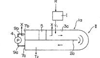
Fig. 9 represents primary treatment briefly and adopts jet to subtract secondary treatment device that can engineering and the advanced treatment apparatus of contact material is set and the front view of the waste disposal plant established.
Figure 10 dispenses the primary treatment part, represents the stereoscopic figure of this waste disposal plant briefly.
Figure 11 be equipped with in the expression circulation water channel contact material, along the partial cross section figure of the X-X line of Fig. 9.
Figure 12 is the sketch chart of another embodiment of expression advanced treatment apparatus.
Figure 13 be expression adopt jet subtract can engineering the dispose of sewage chart of testing data of situation of secondary treatment device and the secondary treatment device that adopts contact material, (a) be the chart of expression BOD change in concentration, (c) being the chart that the full nitrogen concentration of expression changes, (c) is the chart that the expression ammonia nitrogen concentration changes.
The best way that carries out an invention
With embodiment embodiments of the present invention are described below.
At first, referring to figs. 1 through Fig. 8, secondary treatment method and the device that adopts jet to subtract the energy engineering described.
At first, the symbol among Fig. 1 to Fig. 81 (1a, 1b, 1c) expression treatment trough main body.
In the treatment trough main body 1a that roughly is rectangle of the waste disposal plant of pie graph 1 first embodiment of the invention, the central length direction is formed with the next door 2a that an end is in open state in treatment trough, and this next door 2a forms treatment trough the circulation water channel 3a of U-shaped.
Near this circulation water channel 3a, the primary treatment device I of being adjusted (not expressing among the above figure) formations such as groove by screen device, settling bath, device for dehydrating sladge waste, flow is set.Raw waste water R such as following water at first flow into this primary treatment device I, and the rubbish in the raw waste water, impurity are removed, and promptly carry out so-called " primary treatment ".
In primary treatment device I, flow is regulated, form primary treatment water T
1, flow into the circulation water channel 3a that constitutes secondary treatment device II from primary treatment device I.
Recycle pump shown in the symbol 4 is in the water inlet pipe 9a of the water channel terminal part 7a that is connected in circulation water channel 3a and is connected between the rising pipe 9b of the water channel top 7b of portion (forming the water pipe of recirculated water relief outlet), is used for making the treating water in the circulation water channel 3a to circulate.
By changing the output (or velocity of discharge) of the treating water that this recycle pump 4 discharges, just can carry out appropriate selection to the speed of circulation for the treatment of water.
Why in the position near the water channel top 7b of portion weir main body 5 being set, is because will effectively utilize from the flow velocity of above-mentioned recycle pump 4 through the effusive treating water of rising pipe 9b, carries out the anaerobism stirring that the back will illustrate effectively, carries out a biological disposal upon more effectively.
Weir main body 5a shown in Fig. 2 is that a kind of this main body 5a self can be by suitably being chosen in the embodiment that above-below direction moves.
The method that this main body 5a is moved up and down, have in for example that the side embedding water channel sidewall above-below direction of weir main body 5a is the set tongue-and-groove, can at first slide into position arbitrarily, be fixed with suitable way, perhaps gear, rack gear are set at weir main body 5a and water channel sidewall, rotations by gear etc. are set weir main body 5a, be fixed in the optional position, and fixed method etc. can adopt means arbitrarily.
The position of weir main body 5a the most handy machinery, method is regulated automatically, in this case, can consider with the above-mentioned gear of power wheel drive, the gear of rack gear, or weir main body 5a is dangled with the equipment as the simple crane, is fixed in suitable position.
The shape of this weir main body 5a shown in Fig. 2 (a)~(c), has the vertical wall 6a of upstream side, and becomes from the treating water of the weir main body 5a top overflow skew wall 6b of the flowing water face during landing (jet) downwards sideling.
That is to say, vertical wall 6a disposes towards upstream side, play a part to stop treating water, skew wall 6b then plays a part to make the treating water jet landing that is stopped by vertical wall 6a and overflow from this weir main body 5a upper end, promptly constitutes so-called " jet subtract can engineering ".
Skew wall 6b and vertical wall 6a to combine the angle [alpha] that should be able to allow between them variable.Vertical wall 6a combines with this of skew wall 6b, can pass through for example pivot combination, makes skew wall 6b can keep, be fixed on angle arbitrarily.
By changing this angle [alpha], speed or angle that just variable treating water flows down from skew wall 6b.In other words, just can adjust the amount of being involved in of air, promptly change aeration rate, carry out the adjustment of aerobic treatment by the jet for the treatment of water, the variation of landing state.During usually conduct, the angle [alpha] of skew wall 6b is adjusted to about 45 ° ± 5~10 °.
Below, to adopt waste disposal plant of the present invention once, the secondary sewage treatment method is specifically described.
At first, as previously mentioned, raw waste water R such as following water flow into by the screen device (not expressing among the figure) of removing solid substance, allow the settling bath (not expressing among the figure) that outstanding absurd creature post precipitation removed, the flow of adjusting flow adjust the primary treatment device I that groove (not expressing among the figure) waits formation, are processed into primary treatment water T
1After, supply with circulation water channel 3a carry out a biological disposal upon (screen device, settling bath and flow are adjusted each pretreating device such as groove can adopt proper device according to the water quality for the treatment of water).
In circulation water channel 3a, drop into the active sludge that planktonic organism is handled usefulness earlier, keep circulation with the treating water that flows into.Like this, the dirty material in the treating water in circulating, under anaerobism or aerobic or condition that both have concurrently, is decomposed with biological method and is removed (calling " secondary treatment " in the following text).
Treating water T through this secondary treatment
2Take away from circulation water channel 3a by for example upflow tube (or communicating pipe), the after-treatment device of not expressing among the figure such as introducing precipitation process groove (under the situation of secondary treatment constipation bundle) is perhaps introduced advanced treatment apparatus described later (carrying out under the situation of advanced treatment again).The supply for the treatment of water or withdrawing device can adopt any suitable device.
Below " secondary treatment " is described in more details, be provided with jet subtract can engineering the secondary treatment device in, when only carrying out the aeration processing, shown in Fig. 2 (a), weir main body 5a is made a decision at bottom land B, the round-robin treating water all from top overflow and the jet landing of weir main body 5a, utilizes the air that is involved in to carry out so-called " aeration ".Like this, the molten amount of handling water oxygen that is stored in is improved, just the biological treatment (calling " aerobic treatment " in the following text) that can enliven by aerobic microorganism.
On the other hand, under the situation that circular treatment water is carried out a biological disposal upon by anaerobion, shown in Fig. 2 (c), weir main body 5a is disposed at the top, the top layer part of recirculated water is stopped, and circular treatment water forms undercurrent by the deposition opening portion 8 that forms between weir main body 5a and the bottom land B.
Like this, because treating water does not carry out aeration not from the top overflow of weir main body 5a, have only undercurrent water to carry out anaerobic biological treatment (calling " anaerobic treatment " in the following text).
Shown in Fig. 2 (b), as weir main body 5a being fixed on the roughly mid-way of above-below direction, just can allow the part of circular treatment water from the top overflow of weir main body 5a, jet, carry out aerobic treatment, allow circular treatment water pass through simultaneously, carry out the anaerobic treatment of undercurrent water from the deposition opening portion 8 that forms between weir main body 5a and the bottom land B.
Like this, as long as according to the water quality for the treatment of water,, just can freely adjust overflow water aerobic treatment and ratio to undercurrent water anaerobic treatment in the fixed position of above-below direction adjusted weir main body 5a.For example,, just can increase the amount of anaerobic treatment, promote nitrated, denitrogenation processing containing the many sewage of ammonia-state nitrogen.
In other words, secondary treatment device of the present invention not only can carry out the aerobic treatment of aeration and the anaerobic treatment of aeration not simultaneously, and the ratio that can suitably regulate two kinds of processing, is a kind of useful waste disposal plant of suitable water quality wide range.
Secondary treatment device of the present invention can be as shown in Figure 3, adopts the weir main body 5b with the flashboard 11 that can slide along vertical wall 6a above-below direction.
This weir main body 5b is fixed in the roughly mid-way of groove 1a, is formed with deposition opening portion 8 all the time between weir main body 5b and bottom land B.But, by the flashboard 11 on the vertical wall 6a face that is contained in weir main body 5b along the sliding up and down of vertical wall 6a, just can be with deposition opening portion 8 freely openables.
This flashboard 11 shown in Fig. 3 (b), is set to slidably to the higher position, top than fixed weir main body 5b.Like this, just can stop flowing of circular treatment surface layer of water fully, only the undercurrent water by deposition opening portion 8 be carried out anaerobic treatment.
As long as adjust the position of flashboard 11, just can make the top overflow of recirculated water from fixed weir main body 5b, allow recirculated water pass through deposition opening portion 8 simultaneously and form undercurrent, can also suitably select both ratios.
As shown in Figure 4, also can above-mentioned flashboard 11, and cross-section groove 3a is provided with the open and close valve 12 of shapes such as butterfly valve at the position of deposition opening portion 8.This structure shown in these figure (a) and (b), by the rotation of open and close valve 12, can be regulated the opening amount of deposition opening portion 8, regulates the ratio of overflow or undercurrent amount.
In addition, can also adopt the weir main body 5c shown in Fig. 5 (a) and (b) with tabular vertical wall 6a.This vertical wall 6a is that the axial downstream direction is fascinated as the upper end position with weir main body 5c, forms deposition opening portion 8, just then can form undercurrent.
As long as adjust the amount of fascinating of vertical wall 6a, just can make the top overflow of recirculated water from fixed weir main body 5c, allow recirculated water pass through deposition opening portion 8 simultaneously and form undercurrent, can also suitably select both ratios.This point is the same with above-mentioned weir main body 5a, 5b.
Under the situation that adopts weir main body 5b, 5c, also the situation with 5a is the same, and the angle of skew wall 6b is variable, can change speed and angle that treating water flows down from skew wall 6b.
Fig. 6 has represented to be provided with at the bottom land B of deposition opening portion 8 peripheries of weir main body 5a lower portion the embodiment on sinking weir 10.
The disorderly effect of undercurrent water (at bottom land B mobile treating water) that makes by deposition opening portion 8 has been played on sinking weir 10 in the present embodiment, by this sinking weir 10 is set, can improve the effect that anaerobism stirs.
In this case, as set out water pipe 9b, circular treatment water is entered to the direction on sinking weir, circular treatment water impacts sinking weir 10 effectively, therefore can positively improve the effect that anaerobism stirs (when adopting weir main body 5b, 5c too, as sinking weir 10 is set, can obtain same effect).
In the embodiment of above explanation, that adopt is the U-shaped circulation water channel 3a that is provided with along the next door 2a of treatment trough main body 1a length direction, in narrow space, also can be shown in the embodiment of Fig. 7, the next door 2b of intersection is set in roughly being foursquare groove body 1b, forms mazy circulation water channel.
Under the situation of this embodiment, the entire sewage treatment unit is compact more in the plane.Shape, the installation method of weir main body 5 (5a, 5b, 5c), and the method to set up of sink weir 10, rising pipe 9b is the same to structure shown in Figure 6 with above-mentioned Fig. 1.
In addition, can also shown in the embodiment of Fig. 8, adopt spiral (claiming vortex again) groove 1c, make circulation water channel 3c form volution in the plane.In this case, mobile smooth and easy in the circulation water channel 3c is simultaneously because of secondary treatment water T
2Discharge from the space that is formed at central part, the space of this central part can utilize as for example settling bath, makes device compact more.
Below, according to Fig. 9 to Figure 12, to describing with the embodiment that above-mentioned way has been carried out the advanced treatment apparatus that the treating water of secondary treatment further purifies.
At first, Fig. 9, symbol II shown in Figure 10 represent to adopt jet to subtract the secondary treatment device of energy engineering, and the symbol III shown in this figure represents to adopt the advanced treatment apparatus of contact material.
Two device II, III dispose side by side, have rectangular outward appearance generally.In the treatment trough 1 of each device II, III, be formed with an end open next door 2a, 2c respectively, form circulation water channel 3a, the 3d of U-shaped.
In secondary treatment device II, as mentioned above, circulation water channel 3a be provided with midway as jet subtract can engineering weir main body 5 (5a, 5b, 5c), and in the advanced treatment apparatus III, contact material then is being set above water channel is at regular intervals keeping rod 13,3d is cross-section with the circulation water channel, respectively should on the rod 13 many fibrous contact materials 14 be set vertically at regular intervals.
The fibrous contact material 14 that amplifies expression in Figure 11 is the stranded fibrous bundles that form such as superfine carbonizedfibres by necessary amount, and keeping rod 13 is to make at the surface coverage vinylchlorid of iron staff, insulate with carbonizedfibres.Keep rod 13 by installation tool 20 supportings (with reference to Figure 11) that are contained in groove body 1 side wall upper part that forms circulation water channel 3d.
Below, advanced treatment apparatus is carried out specific description, through the secondary treatment water T of secondary treatment device processing
2, fetch from circulation water channel 3a by upflow tube (claiming communicating pipe again) 15, flow into the settling bath 16 of advanced treatment groove III.In this settling bath 16, secondary treatment water T
2Carry out solid-liquid separation, be separated into sedimentation mud and primary water.
As without upflow tube (claiming communicating pipe again) 15, then can replace air lift pump 21 (in Figure 10, not expressing) with reference to Figure 12, adopt aeration and the mode that promotes to flow and carry out simultaneously, with secondary treatment water T
2Suct and drop among the water channel 3d.Therefore in this case, because can carry out aeration by landing again, can improve the efficient of aerobic treatment (organic oxygenolysis, ammonia-state nitrogen nitrated) and anaerobic treatment (denitrogenation of nitric nitrogen).Can also adopt any Water raisers such as spiral pump according to the water quality of processed water.
Then, flow into the secondary treatment water T of water channel 3d
2Be introduced in the microbial film district 19a (hanging the circulation water channel position of fibrous contact material 14) that the certain position of circulation water channel 3d forms from settling bath 16.
When beginning to utilize the advanced treatment of microbial film district 19a, with existing activated sludge process, perhaps the microbial film contact oxidation method is the same, throw in kind of a mud in water channel, through raising and train of certain hour.Like this, on each fibrous contact material 14, just can form a large amount of microbial films securely.
Consequently, the upstream side in the microbial film district carries out the aerobic treatment bio-oxidation by remaining oxygen, and the remaining composition that does not obtain handling during with secondary treatment is removed, and simultaneously deposits the downstream side part that oxygen has been consumed and carries out the anaerobic denitrogenation processing molten.
When setting the scope of this microbial film district 19a,, suitably adjust interval, quantity and aeration rate and the speed of circulation of fibrous contact material 14 because of the water quality of processed water, the water quality of the water of releasing are investigated.
In the present embodiment, fixedly the maintenance rod 13 of contact material 14 is erected on the circulation water channel 3d, loads onto and takes off conveniently, is easy to so adjust operation.The installation method of contact material 14 is not limited to the method for embodiment, can adopt any suitable method, but can load onto the way of taking off from water channel top as adopting, and then the setting operation ratio of microbial film district 19a is easier to.
In the present embodiment, because adopted superfine fiber to be twisted into fibrous bundle, so in water channel, each single fiber scatters, microorganism is respectively attached to each single fiber surface, thus microorganism to adhere to density big, and can adhere to securely, do not peel off fully.Also have, each contact material 14 hangs down in water, can joltily adorn, so biomembranous formation is easy, and firmly.
Like this, because in circulation water channel 3d, fibrous contact material 14 is hanging, so can not hinder circulating for the treatment of water, can not cause sludge blockage during biological treatment, owing to adopted superfine fiber contact material 14, therefore biomembranous density is improved.So the efficient of processing is improved, peeling off of mud is few, and the solid-liquid separation for the treatment of water is simple.Compare with existing circulation water channel processing, pile up because do not have mud, velocity of flow can be less, can further improve the efficient and the water quality treatment of processing.
The advanced water treatment T that in the flowing of above-mentioned microbial film district 19a, has carried out biological treatment
3, in final treatment trough 17, removed the dirty material that still contains in this treating water after, from circulation water channel 3d, extracted out, through releasing after the necessary aftertreatment 18.
That Figure 12 represents is the embodiment of the another kind of advanced treatment apparatus of compact type.
In this embodiment, secondary treatment water T2 is flowed into by suitable way after the settling bath 16, is drawn up by air lift pump 21a, drops among the circulation water channel 3e, and aeration flows with promotion and carries out flow circuit in oblong circulation water channel 3e simultaneously.
After this, by with Fig. 9, embodiment shown in Figure 10 microbial film district 19b with spline structure, carry out biological treatments such as denitrogenation, draw up by the air lift pump 21b that is disposed at circulation water channel 3e terminal part 22, drop to the top portion 23 of circulation water channel 3e, circulate once more (in the embodiment of Fig. 9, secondary treatment II shown in Figure 10, the air lift pump of not expressing among the also available figure is extracted treating water out from the terminal part of circulation water channel 3d, drop to the top portion of circulation water channel 3d, circulate repeatedly).
Advanced water treatment T after advanced treatment finishes
3,, after the final treatment trough 17 of spatial, the rear treating groove 18 that are arranged at the inboard formation of circulation water channel 3e carry out aftertreatment, banish outside the auto levelizer by extraction midway from circulation water channel 3e.
Below, according to Figure 13, to adopt jet subtract can engineering the secondary treatment device aerobic treatment of carrying out, and the testing data aerobic, anaerobic treatment that adopts the advanced treatment apparatus of contact material to carry out describes.
Test is at BOD concentration, full nitrogen concentration, ammonia nitrogen concentration, the former water of inflow (R), secondary treatment water (T
2) and advanced water treatment (T
3) carry out, respectively at measuring on June 6th, 1997, June 27 the same year with July 3 the same year.
Figure 13 is with longitudinal axis indicated concentration (mg/L), and transverse axis represents that respectively measuring day represents measurement result, and each measures the former water of inflow (R), the secondary treatment water (T of day
2) and advanced water treatment (T
3) measured value be drawn as column respectively.
Shown in Figure 13 (a), compare with each BOD that measures the former water of inflow (R) of day, can see secondary treatment water (T
2) BOD concentration greatly reduce advanced water treatment (T
3) then reduce more.
That is to say that it is that effectively in the anaerobic treatment in advanced treatment process, contact filtering material has been caught aerobic outflow mud, has brought into play stable detergent power that aerobic secondary treatment combines with the anaerobic advanced treatment.
And for example shown in Figure 13 (b), even if from the outset only through short time (about one month), can confirm to have carried out full nitrogen and handle, the data on July 3 show that full nitrogen concentration has dropped to below the 10mg/L.As the anaerobic treatment ability of further raising contact filtering material, full nitrogen concentration is expected further to be reduced.
In addition, shown in Figure 13 (c), ammonia nitrogen concentration in time passing and reduce, be prerequisite with removing of full nitrogen, nitrated can carrying out well, from the data on July 3, the ammonia-state nitrogen that flows into former water R is almost completely by nitrated.
As mentioned above, any one above-mentioned embodiment all can improve water quality treatment with simple device.
The possibility of utilizing on the industry
Can find out that from top explanation what the disclosed invention of the application industrially utilized can Can the property following points.
(1) by in the water channel of carrying out a biological disposal upon in effluent cycle, arranges under the formation and can open The jet of mouth subtracts the weir of energy engineering, can only carry out aerobic treatment with overflow, or only carry out with undercurrent Anaerobic Treatment, or not only with overflow, but also carry out aerobic and sewage disposal side Anaerobic Treatment with undercurrent Method can carry out freely selecting or making up to aerobic treatment and Anaerobic Treatment, therefore can basis The water quality of the sewage such as lower water is carried out effective secondary sewage disposal.
(2) be arranged at the opening amount of the weir below in the water channel by adjustment, just the aerobic place of capable of regulating The ratio of reason and Anaerobic Treatment like this, not only can be carried out certainly aerobic treatment and Anaerobic Treatment By selection or combination, and can adjust aerobic treatment and anaerobism place according to the water quality of sewage The ratio of reason is carried out effective secondary sewage disposal.
(3) more particularly, sewage-treatment plant of the present invention will processed water by circulating pump From the terminal part pump of cyclic water channel to its top section, when circulating, at cyclic water channel Dispose midway consisted of by vertical wall and skew wall, as jet subtract can engineering the weir, the weir main body from Body can one moves up and down, and perhaps forms peristome between it is bottom water channel, will be arranged at The flashboard of the vertical walls of fixing above-mentioned weir main body moves up and down, perhaps at it bottom water channel Between form peristome, allow the open and close valve that is arranged at fixing above-mentioned weir main body lower opening section turn to Moving, perhaps allow the tabular vertical wall that consists of the weir main body fascinate, make from the recirculated water of weir top overflow Aerobic treatment is carried out in the jet landing, makes the undercurrent recirculated water by the below, weir carry out Anaerobic Treatment, Can freely select to carry out both has concurrently or only has a kind of processing.
That is to say that when the weir main body that can move up and down was fixed in the top position, recirculated water was not From the top overflow on this weir, recirculated water is only heavy from what form between this weir and the cyclic water channel bottom again Long-pending peristome flows out, and only carries out Anaerobic Treatment.
When the weir main body makes a decision at bottom land, just can only process water from this weir main body top overflow Form the aerobic treatment of jet landing. Be fixed in water channel above-below direction centre position in the weir main body The time, process water from this weir top overflow, recirculated water passes through from the below on this weir simultaneously, forms dark Stream can carry out aerobic treatment and Anaerobic Treatment simultaneously.
Like this, just can provide and by freely selecting the position of weir main body, to carry out aerobic treatment Or allow undercurrent recirculated water carry out Anaerobic Treatment by the peristome of below, weir, can freely select two The person carries out or only carries out a kind of sewage-treatment plant of processing simultaneously.
(4) form peristome as adopting between the weir main body is bottom water channel, allow be arranged at fixing The method that moves up and down of the flashboard of vertical walls of weir main body, and fixing weir main body with Water channel forms the method that peristome arranges open and close valve between the bottom, then can regulate the upper the next of flashboard Put the turned position with open and close valve, select suitably, easily aerobic treatment or Anaerobic Treatment, Or both carry out simultaneously.
(5) method that allows the vertical wall of the above-mentioned weir of formation main body fascinate with respect to skew wall such as employing, Then risen by this vertical wall that can fascinate and select aerobic treatment or Anaerobic Treatment, or both carry out simultaneously The effect of adjustment component, change the opening amount of deposition opening section by the difference of the amount of fascinating, Adjust easily the ratio of aerobic treatment and Anaerobic Treatment.
(6) by the cyclic water channel bottom in the weir body peripheral edge sinking weir is set, makes by under the weir It is disorderly that the circular treatment current of side become, and produces the effect that stirs, and can improve undercurrent recirculated water The anaerobism mixing effect, open to deposition opening section such as the discharge outlet of above-mentioned circulating pump, then anaerobism is stirred Mixing effect can be further enhanced.
(7) as the next door of intersection is set, form labyrinth type in roughly being foursquare groove body Cyclic water channel, perhaps form the helical water channel in plane, process water and just can follow swimmingly Ring also can carry out the secondary sewage disposal effectively in narrow place.
(8) adopt jet subtract can engineering the after-treatment device obtain the basis of above-mentioned effect On, adopt again contact material, in cyclic water channel, form the advanced treating dress in biomembrane district The sewage disposal of putting can effectively be carried out organic decomposition and remove and denitrogenation.
(9) the present invention not only provides a kind of equipment simple, low price, and maintenance management is held Easily, be suitable for the middle and small scale sewage disposal, the efficiently sewage disposal of aerobic, anaerobism dual-purpose Method and apparatus, but also provide a kind of can be according to the sewage quality place that freely disposes of sewage Reason method and sewage-treatment plant.
Claims (16)
1. one kind allows primary treatment water round-robin biological treatment secondary sewage treatment method in water channel of having removed contained rubbish, impurity etc. in the sewage, but it is characterized in that in above-mentioned water channel, being provided with the lower portion opening and form the weir that jet subtracts the energy engineering, can only carry out aerobic treatment with overflow, only carry out anaerobic treatment with undercurrent, also can both use overflow, use undercurrent again, carry out aerobic and anaerobic treatment.
2. sewage water treatment method according to claim 1 is characterized in that freely adjusting aerobic treatment and anaerobic treatment ratio by the lower opening amount of regulating above-mentioned weir.
3. one kind allows removed the secondary sewage treatment device that the primary treatment water of contained rubbish, impurity etc. is carried out a biological disposal upon in the sewage in the circulation water channel,
It is characterized in that being provided with the treating water that will suck from above-mentioned circulation water channel terminal part and be discharged to the recycle pump of water channel top portion, and be arranged at the circulation water channel, constitute, form the weir that jet subtracts the energy engineering midway by vertical wall and skew wall,
By moving up and down of above-mentioned weir main body self, between weir main body and water channel bottom, form peristome, be arranged at the sliding up and down of flashboard of the vertical walls of the above-mentioned weir of fixed main body, between weir main body and water channel bottom, form peristome, be arranged at the rotation of open and close valve of the lower opening portion of the above-mentioned weir of fixed main body, and the vertical wall that constitutes above-mentioned weir main body is in any methods such as fascinating of water channel direction, allow undercurrent recirculated water pass through from the peristome of below, weir, carry out anaerobic treatment, allow and form the jet landing from the recirculated water of weir top overflow, aeration, carry out aerobic treatment, can freely select both to carry out simultaneously, or carry out separately.
4. waste disposal plant according to claim 3, the angle that it is characterized in that being formed at the skew wall in main body downstream side, above-mentioned weir is variable.
5. waste disposal plant according to claim 3 is characterized in that being provided with the sinking weir in the circulation water channel bottom of above-mentioned weir body peripheral edge.
6. waste disposal plant according to claim 4 is characterized in that being provided with the sinking weir in the circulation water channel bottom of above-mentioned weir body peripheral edge.
7. waste disposal plant according to claim 5, the water port that it is characterized in that above-mentioned recycle pump is towards deposition opening portion that the formation undercurrent that is formed at below, above-mentioned weir is used.
8. waste disposal plant according to claim 6, the water port that it is characterized in that above-mentioned recycle pump is towards deposition opening portion that the formation undercurrent that is formed at below, above-mentioned weir is used.
9. throw in the secondary treatment water of handling with claim 1 or the described sewage water treatment method of claim 2 for one kind, carry out the waste disposal plant of advanced treatment again, it is characterized in that being provided with a plurality of elastotic contact materials with the part that can shake because of circulating water flow in circulation water channel water (flow) direction compartment of terrain, these contact materials become biological carrier, form biological treatment zone, allow the secondary treatment water cycle flow, carry out aerobic treatment and anaerobic treatment.
10. throw in the secondary treatment water of handling with claim 3 any one described waste disposal plant to the claim 8 for one kind, carry out the waste disposal plant of advanced treatment again, it is characterized in that being provided with a plurality of elastotic contact materials with the part that can shake because of circulating water flow in circulation water channel water (flow) direction compartment of terrain, these contact materials become biological carrier, form biological treatment zone, allow the secondary treatment water cycle flow, carry out aerobic treatment and anaerobic treatment.
11. waste disposal plant according to claim 9 is characterized in that above-mentioned elastotic contact material, adopts stranded fibrous bundle.
12. waste disposal plant according to claim 10 is characterized in that above-mentioned elastotic contact material, adopts stranded fibrous bundle.
13. waste disposal plant according to claim 9 is characterized in that above-mentioned elastotic contact material, adopts carbonizedfibres.
14. waste disposal plant according to claim 10 is characterized in that above-mentioned elastotic contact material, adopts carbonizedfibres.
15. waste disposal plant according to claim 11 is characterized in that above-mentioned elastotic contact material, adopts carbonizedfibres.
16. waste disposal plant according to claim 12 is characterized in that above-mentioned elastotic contact material, adopts carbonizedfibres.
Applications Claiming Priority (2)
| Application Number | Priority Date | Filing Date | Title |
|---|---|---|---|
| JP149610/97 | 1997-06-06 | ||
| JP14961097 | 1997-06-06 |
Publications (2)
| Publication Number | Publication Date |
|---|---|
| CN1228064A true CN1228064A (en) | 1999-09-08 |
| CN1095449C CN1095449C (en) | 2002-12-04 |
Family
ID=15478977
Family Applications (1)
| Application Number | Title | Priority Date | Filing Date |
|---|---|---|---|
| CN98800773A Expired - Fee Related CN1095449C (en) | 1997-06-06 | 1998-06-05 | Method and apparatus for treating wastewater |
Country Status (5)
| Country | Link |
|---|---|
| JP (1) | JP3285884B2 (en) |
| KR (1) | KR100492683B1 (en) |
| CN (1) | CN1095449C (en) |
| AU (1) | AU725812B2 (en) |
| WO (1) | WO1998055407A1 (en) |
Cited By (5)
| Publication number | Priority date | Publication date | Assignee | Title |
|---|---|---|---|---|
| CN101618924B (en) * | 2009-07-21 | 2012-06-27 | 天津市塘沽鑫宇环保科技有限公司 | Wastewater treatment device |
| EP2831002A4 (en) * | 2012-03-28 | 2015-10-07 | Xylem Ip Man S R L | Treatment plant for sewage treatment |
| CN105481105A (en) * | 2016-01-18 | 2016-04-13 | 马鞍山市三环碧源水处理工程有限公司 | Novel sewage pretreatment equipment |
| CN109231513A (en) * | 2018-10-19 | 2019-01-18 | 四川安达尔环保工程有限公司 | A kind of endogenous pollution governing system |
| CN113307416A (en) * | 2021-06-29 | 2021-08-27 | 洛阳永宁有色科技有限公司 | Multifunctional sewage treatment tank |
Families Citing this family (6)
| Publication number | Priority date | Publication date | Assignee | Title |
|---|---|---|---|---|
| IL127174A0 (en) * | 1998-11-20 | 1999-09-22 | Almog Projects Ltd | Sewage treatment facility and method |
| JP4635318B2 (en) * | 2000-10-03 | 2011-02-23 | 株式会社大林組 | Water purification system |
| DE102005032123A1 (en) * | 2005-07-07 | 2007-01-11 | Mahla, Sylvio | Process and plant for biological wastewater treatment in a circulation zone reactor |
| JP2009195850A (en) * | 2008-02-22 | 2009-09-03 | Soen Co Ltd | Water purifying unit and system |
| US9433905B2 (en) * | 2013-02-20 | 2016-09-06 | Jim Myers & Sons, Inc. | Low profile cascade aerator |
| CN109970184A (en) * | 2019-04-25 | 2019-07-05 | 河南省科学院化学研究所有限公司 | It is a kind of for removing the aerobic biological process for treating of industrial wastewater COD |
Family Cites Families (5)
| Publication number | Priority date | Publication date | Assignee | Title |
|---|---|---|---|---|
| JPS5946191A (en) * | 1982-09-06 | 1984-03-15 | Hitachi Ltd | Dissolved oxygen controller |
| JPS61212393A (en) * | 1985-03-15 | 1986-09-20 | Hitachi Ltd | Method for controlling oxidation ditch |
| JPS61234995A (en) * | 1985-04-10 | 1986-10-20 | Masahiko Irie | Aerating method by falling water stream |
| CZ282411B6 (en) * | 1994-12-02 | 1997-07-16 | Jan Ing. Topol | Waste or sewage water treatment and apparatus for making the same |
| JP2954509B2 (en) * | 1995-02-20 | 1999-09-27 | 徳彦 平野 | Contact filter media in catalytic oxidation water purifier |
-
1998
- 1998-06-05 KR KR10-1999-7000904A patent/KR100492683B1/en not_active IP Right Cessation
- 1998-06-05 CN CN98800773A patent/CN1095449C/en not_active Expired - Fee Related
- 1998-06-05 AU AU75510/98A patent/AU725812B2/en not_active Ceased
- 1998-06-05 WO PCT/JP1998/002501 patent/WO1998055407A1/en active IP Right Grant
- 1998-06-05 JP JP54548998A patent/JP3285884B2/en not_active Expired - Fee Related
Cited By (7)
| Publication number | Priority date | Publication date | Assignee | Title |
|---|---|---|---|---|
| CN101618924B (en) * | 2009-07-21 | 2012-06-27 | 天津市塘沽鑫宇环保科技有限公司 | Wastewater treatment device |
| EP2831002A4 (en) * | 2012-03-28 | 2015-10-07 | Xylem Ip Man S R L | Treatment plant for sewage treatment |
| CN105481105A (en) * | 2016-01-18 | 2016-04-13 | 马鞍山市三环碧源水处理工程有限公司 | Novel sewage pretreatment equipment |
| CN105481105B (en) * | 2016-01-18 | 2017-10-20 | 马鞍山市三环碧源水处理工程有限公司 | A kind of new polluted water pretreatment apparatus |
| CN109231513A (en) * | 2018-10-19 | 2019-01-18 | 四川安达尔环保工程有限公司 | A kind of endogenous pollution governing system |
| CN113307416A (en) * | 2021-06-29 | 2021-08-27 | 洛阳永宁有色科技有限公司 | Multifunctional sewage treatment tank |
| CN113307416B (en) * | 2021-06-29 | 2023-04-07 | 洛阳永宁有色科技有限公司 | Multifunctional sewage treatment tank |
Also Published As
| Publication number | Publication date |
|---|---|
| KR20010029446A (en) | 2001-04-06 |
| AU725812B2 (en) | 2000-10-19 |
| CN1095449C (en) | 2002-12-04 |
| WO1998055407A1 (en) | 1998-12-10 |
| AU7551098A (en) | 1998-12-21 |
| KR100492683B1 (en) | 2005-06-10 |
| JP3285884B2 (en) | 2002-05-27 |
Similar Documents
| Publication | Publication Date | Title |
|---|---|---|
| CN1231420C (en) | Batch sewage treatment device using biofiltering method and its sewage treatment method | |
| CN1186109C (en) | Biological filtering water treatment equipment | |
| CN1095449C (en) | Method and apparatus for treating wastewater | |
| CN1466553A (en) | method for purifying sewage | |
| CN1829666A (en) | Method and installation for the biological treatment of water using activated sludge and comprising aeration regulation | |
| US20150191382A1 (en) | Systems and methods for waste treatment | |
| KR20190009467A (en) | Green algae prevention apparatus using sunlight generation and methode thereof | |
| CN207072847U (en) | A kind of tower integrated sewage treating apparatus | |
| CN1277942A (en) | System for treatment of water or wastewater, and method using such system | |
| JP2017516658A (en) | Clarification method of waste water | |
| CN1256290C (en) | Process and apparatus for treating waste water | |
| CN102198971B (en) | Upward flow biological aerated filter and aeration method thereof | |
| JP4409532B2 (en) | Apparatus for treating wastewater containing high-concentration nitrogen such as livestock wastewater and manure, and its treatment method | |
| CN106495410A (en) | A kind of intensive rural domestic sewage treatment system | |
| CN105967333A (en) | Integrated equipment and method for treating town domestic sewage | |
| KR102070594B1 (en) | Circulate and filter type water collecting apparatus | |
| JP2011072936A (en) | Fluidized bed type biological treatment apparatus | |
| CN206940701U (en) | Circulation high-efficiency sewage biological cleaning integrated reactor in a kind of | |
| JP7016622B2 (en) | Membrane separation activated sludge treatment equipment and membrane separation activated sludge treatment method | |
| JP2010022946A (en) | Sewage treatment device | |
| CN1118154A (en) | Method and apparatus for biological activation waste water treatment | |
| CN107445296B (en) | Activated sludge water quality purifying device | |
| CN108947147A (en) | A kind of DMF advanced waste treatment apparatus | |
| CN110028206A (en) | A kind of processing method of woven fabric waste water | |
| CN209412044U (en) | BMR biological cleaning dephosphorization all-in-one machine |
Legal Events
| Date | Code | Title | Description |
|---|---|---|---|
| C06 | Publication | ||
| PB01 | Publication | ||
| C10 | Entry into substantive examination | ||
| SE01 | Entry into force of request for substantive examination | ||
| C14 | Grant of patent or utility model | ||
| GR01 | Patent grant | ||
| C19 | Lapse of patent right due to non-payment of the annual fee | ||
| CF01 | Termination of patent right due to non-payment of annual fee |