CN1217792C - Fixing device - Google Patents
Fixing device Download PDFInfo
- Publication number
- CN1217792C CN1217792C CN028031474A CN02803147A CN1217792C CN 1217792 C CN1217792 C CN 1217792C CN 028031474 A CN028031474 A CN 028031474A CN 02803147 A CN02803147 A CN 02803147A CN 1217792 C CN1217792 C CN 1217792C
- Authority
- CN
- China
- Prior art keywords
- fixture
- roller
- sheet spare
- spare
- parts
- Prior art date
- Legal status (The legal status is an assumption and is not a legal conclusion. Google has not performed a legal analysis and makes no representation as to the accuracy of the status listed.)
- Expired - Fee Related
Links
Images

Classifications
-
- B—PERFORMING OPERATIONS; TRANSPORTING
- B41—PRINTING; LINING MACHINES; TYPEWRITERS; STAMPS
- B41F—PRINTING MACHINES OR PRESSES
- B41F13/00—Common details of rotary presses or machines
- B41F13/08—Cylinders
- B41F13/24—Cylinder-tripping devices; Cylinder-impression adjustments
-
- B—PERFORMING OPERATIONS; TRANSPORTING
- B41—PRINTING; LINING MACHINES; TYPEWRITERS; STAMPS
- B41F—PRINTING MACHINES OR PRESSES
- B41F31/00—Inking arrangements or devices
- B41F31/30—Arrangements for tripping, lifting, adjusting, or removing inking rollers; Supports, bearings, or forks therefor
-
- F—MECHANICAL ENGINEERING; LIGHTING; HEATING; WEAPONS; BLASTING
- F16—ENGINEERING ELEMENTS AND UNITS; GENERAL MEASURES FOR PRODUCING AND MAINTAINING EFFECTIVE FUNCTIONING OF MACHINES OR INSTALLATIONS; THERMAL INSULATION IN GENERAL
- F16C—SHAFTS; FLEXIBLE SHAFTS; ELEMENTS OR CRANKSHAFT MECHANISMS; ROTARY BODIES OTHER THAN GEARING ELEMENTS; BEARINGS
- F16C13/00—Rolls, drums, discs, or the like; Bearings or mountings therefor
- F16C13/02—Bearings
-
- F—MECHANICAL ENGINEERING; LIGHTING; HEATING; WEAPONS; BLASTING
- F16—ENGINEERING ELEMENTS AND UNITS; GENERAL MEASURES FOR PRODUCING AND MAINTAINING EFFECTIVE FUNCTIONING OF MACHINES OR INSTALLATIONS; THERMAL INSULATION IN GENERAL
- F16C—SHAFTS; FLEXIBLE SHAFTS; ELEMENTS OR CRANKSHAFT MECHANISMS; ROTARY BODIES OTHER THAN GEARING ELEMENTS; BEARINGS
- F16C23/00—Bearings for exclusively rotary movement adjustable for aligning or positioning
- F16C23/02—Sliding-contact bearings
-
- F—MECHANICAL ENGINEERING; LIGHTING; HEATING; WEAPONS; BLASTING
- F16—ENGINEERING ELEMENTS AND UNITS; GENERAL MEASURES FOR PRODUCING AND MAINTAINING EFFECTIVE FUNCTIONING OF MACHINES OR INSTALLATIONS; THERMAL INSULATION IN GENERAL
- F16D—COUPLINGS FOR TRANSMITTING ROTATION; CLUTCHES; BRAKES
- F16D63/00—Brakes not otherwise provided for; Brakes combining more than one of the types of groups F16D49/00 - F16D61/00
-
- F—MECHANICAL ENGINEERING; LIGHTING; HEATING; WEAPONS; BLASTING
- F16—ENGINEERING ELEMENTS AND UNITS; GENERAL MEASURES FOR PRODUCING AND MAINTAINING EFFECTIVE FUNCTIONING OF MACHINES OR INSTALLATIONS; THERMAL INSULATION IN GENERAL
- F16D—COUPLINGS FOR TRANSMITTING ROTATION; CLUTCHES; BRAKES
- F16D2121/00—Type of actuator operation force
- F16D2121/02—Fluid pressure
Abstract
The invention relates to a fixing device for clamping two radially displaceable elements.
Description
Technical field
The present invention relates to a kind of fixture, be used for having at least two devices and fix at the relatively-movable member of an adjustment direction to one.
Background technology
Common printing machine for example has a plurality of rollers, particularly ink roller in the rotary press, described ink roller is used for the printing ink of print cartridge is passed to plate cylinder.By ink roller realize to attached to the printing ink on the plate cylinder quantitatively, thereby realize printing ink transmission as the film of certain thickness standard.Therefore can realize waiting the compensation of disturbing such as velocity variations and rotation vibrations.
Also be provided with dampener in addition in printing machine, described dampener is used for and will passes to printing equipment such as wetting agents such as water.
Usually roller is to being made of the roller that is in contact with one another, and wherein at least one roller has the rolling drum surface that is made of elastomeric material, thereby this rolling drum surface can slightly be out of shape at least according to the combined pressure of relative roller.Result as the roll surface strain is formed on linearly extended contact range between the roller, and described contact range is known as contact zones.Can change the width of contact zones by the adjustment of combined pressure between pair roller.Wherein the width of contact zones will produce very big influence to print result.If for example contact zones are narrow in printing equipment, then can not transmit sufficient printing ink, on the contrary the damage of the extruding merit that resilient roller will be subjected to producing therein under the wide situation of contact zones.
For particularly respectively according to condition of work, for example the temperature of printing machine with and the degree of wear can correctly adjust all the time the width of contact zones, being provided with of roller must be adjustable, thereby utilizes executive component described roller to be pushed on the direction of relative roller with adjustable power.When between two rollers, realizing correct combined pressure, fixture is controlled, realize to relative fixed, so that can keep combined pressure constantly with respect to first roller of second roller.
In DE 197 19 305 A1, disclosed a kind of device that is used to adjust two combined pressures between the roller.In described bearing was provided with, the roller of adjustable setting was pressed on the relative roller by a spring that is supported on the press rack.Therefore always form certain combined pressure between two rollers according to selected spring characteristic curve.Realize roller fixing in the combined pressure position with clamp mechanism, be fixed on the frame of printing machine by frictional fit by the clamp mechanism roll shaft with clamping bar and clamping plate.
Disclosed a kind of device that pair roller carries out semi-automatic adjustment that is used in DE 199 19 733 A1, wherein the roller of adjustable setting is fixed on the roller seat, and roller seat is set on the frame support that is fixedly installed on the frame.Roller seat and frame support can relatively move and interconnect by elastic component.Wherein elastic component has certain prestressing force, thereby the adjustable roller that is arranged on the roller seat is pressed on the relative roller with certain combined pressure.Have a stop bolt that is used to realize roller seat stop on frame support, the feeding by the stop bolt make roller seat by frictional fit ground clamping on frame support.
In DE 42 31 673 1, disclosed a kind of device that pair roller is adjusted that is used for, wherein at first utilize the balancing gate pit that roller is moved radially and then pair roller fix.
In DE 30 46 989 C3, disclosed the device that a kind of clutch that is used to adjust top press roll is pressed.Wherein the rotation of synchronizing shaft is fixed by the single piece type brake.
Summary of the invention
The objective of the invention is to propose a kind of fixture.
The technical scheme that realizes described purpose is as follows:
A kind of fixture, being used for having at least two devices at the relatively-movable member of an adjustment direction to one fixes, but wherein at least fixture parts and first member and at least another parts be connected with second member and the described parts frictional fit of the fixture joint that interfixes wherein, wherein fixture has at least three sheet spares, described part is provided with in proper order, wherein said part alternately is connected with parts or another parts of fixture respectively, wherein each sheet spare have respectively at least one rubbing surface and adjacent sheet spare fit and wherein sheet spare fixed mutually, realization is fixing to clamping device, it is characterized in that sheet spare can relatively move on the plane by the rubbing surface definition.
The advantage that adopts the present invention to realize especially is, this apparatus structure is compact especially and take little space and can realize.This point is to be clamped the adjustment that realizes adjustable member by frictional fit mutually by a plurality of parts to realize.By to a plurality of, the order of especially a plurality of this parts is provided with and will be distributed in fixing required frictional force on a plurality of rubbing surfaces between the sheet spare.By the clamping of sheet spare that order is provided with, clamping force interacts respectively on all rubbing surfaces.
For example from sheet spare clutch is known corresponding sheet spare arranged, described part clutch is used for being connected with the friction of the axle of rotary setting.The difference of fixture of the present invention and known sheet spare clutch is that sheet spare can relatively move at least in one direction and can relatively move and then be fixed according to the gap between the member of the fixture in certain adjusting range.Adjust to move and be unlike in the sheet spare clutch in the mode of rotation or rotation and carry out, but realize that in the mode of translation on the plane described plane constitutes the orientation of sheet spare rubbing surface.
Say in principle as clamping device, can use all parts or structure that all are clamped sheet spare mutually under the situation that adds sufficient extruding force.It is useful especially constituting clamping device with prestressed spring spare.When fixture is added in a very big elastic force on the sheet spare by a prestressed spring spare during in the fixed position, realize stable fixing of the mutual frictional fit of sheet spare.Thereby can avoid for example fixture being released unexpectedly owing to cutting off the power supply such as what in common clamping device, be afraid of most to occur.In order to unclamp clamping device, so that the member to fixture is adjusted, fixture is provided with an adjustment part in the present embodiment, utilizes described adjustment part can realize compression to spring part, thereby sheet spare is depressurized and realizes relatively moving of sheet spare.
Can adopt drive unit arbitrarily in principle, for example electric, hydraulic pressure or pneumatic system realizes the control to spring part.If adjustment part is a roofbolt that movably is arranged in the balancing gate pit, then be useful especially.By pressure medium, for example pressure air or hydraulic fluid etc. are to the loading of balancing gate pit, and the elastic force that roofbolt will overcome spring part is moved, thereby sheet spare is depressurized.
The advantage that is used to adjust the device of the combined pressure between roller equally also is compact conformation, and described compact structure can adopt the design of recommendation to be achieved.Identical with prior art, roller is fixed on the roller seat, and described roller seat is arranged on the frame support movably.Frame support or be fixedly installed on the frame of printing machine perhaps is arranged on the corresponding adjusting device, the adjustment that described adjusting device is for example pressed the roller and the corresponding clutch of corresponding roller that are arranged on the roller seat.
On the roller seat or frame support be provided with a space, the part of frame support or roller seat embeds in this space.The size in selected part or space should make between space and part and form a gap, and described gap constitutes the adjusting range between roller seat and frame support.In this gap, realize relatively moving of roller seat and frame support.Adjust to move required adjustment power or in order to make the first roller roof pressure on relative roller with certain combined pressure in order to add, be provided with at least one executive component in the gap, described executive component is with pulling force and/or pressure is added on the roller seat and described executive component is supported on the frame support.Because executive component is arranged in the gap between frame support and the roller seat, thereby has realized special compact structure.Wherein the space is arranged on and also is arranged on the roller seat unimportantly on the frame support, and these two kinds of schemes all are that the phase trans-substitution is associated.
On the design principle of the part in space and the embedding space can be also can carry out adaptive adjustment according to applicable cases arbitrarily.So can associate, the space be rectangle and only have a gap corresponding to the part that embeds within it in one direction, thereby only to adjust on the direction at one be adjustable to roller seat.If in contrast, for example, then need do and adjust at all directions pair roller because the roller that is arranged on the roller seat must be fitted with a plurality of rollers, then preferably space and part are respectively rotational symmetric, thereby form an annular gap between the two.Thereby can realize roller seat an adjustment of adjusting adjustment directions different on the plane corresponding to frame support, wherein the width of annular gap limits and adjusts the adjusting range that moves.
At roller seat corresponding to frame bracket in various adjustment directions, when for example on whole adjustment plane, adjusting, then, need a plurality of executive components in order to realize that required for this reason adjustment moves.So according to one preferred embodiment, between roller seat and frame support, be provided with three executive components at least, utilize described executive component can with first roller respectively roof pressure on different directions.Thereby by making a concerted effort to be added on the roller seat on the direction and be added on the roller that is arranged on the roller seat to being implemented in arbitrarily by the corresponding selection of the added power of described executive component and by combination control respectively to different executive components.Preferably executive component is distributed in the gap between roller seat and the frame support with star fashion.When relatively being arranged on four executive components in the gap respectively, then therefore can avoid the inclination of executive component reliably, this is because also be compressed event because the driving of executive component is separately positioned on the executive component on opposite.
Say in principle and can design executive component arbitrarily.Can certainly associate the system electric or piezoelectricity that adopts.If executive component is a kind of pressure body that loads with pressure medium then is useful especially.When adopting hydraulic oil, then can produce very high pressure with corresponding very big adjustment power as pressure medium.
According to one preferred embodiment, can adopt precompressed gas, particularly compressed air as pressure medium, also be useful especially.Because gas is compressible in principle, so adopt precompressed gas can produce the elasticity that acts between frame support and the roller seat as pressure medium.By damping for example can compensate since uneven or not the circle machinery that may cause disturb.In most printing machine, had compressed air in addition as the energy transmission medium.
The device that is used to adjust the combined pressure between the roller that can adjust setting and the relative roller also can be used for adjusting roller and the combined pressure between another roller or the adjustment of tripping of setting.Certainly to select the adjusting range of frame support and roller seat greatly fully for this reason, adjust required adjustment and move so that can realize tripping.Must corresponding selection be suitable for the executive component between frame support and roller seat that this adjustment is moved in addition.For the adjustment that the influence realization that is not subjected to device control is pressed clutch,, then be useful especially if device is fixed on the tripping adjusting device that adds.Described tripping device for example is a swing arm, utilizes described swing arm can make frame combined pressure position and tripping position between the swing of frame support corresponding to printing machine.
Because fixture is arranged on one and is used to adjust the device of two combined pressures between the roller, so further improved the compactedness of device.
Description of drawings
If fixture is extended with the coaxial axis along device of roller that is arranged on the roller seat, then is useful especially for this reason.
To contrast accompanying drawing below is described further embodiments of the invention.Shown in the figure:
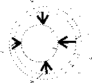
Fig. 1 is the generalized section of fixture;
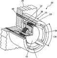
Fig. 2 is a profile of adjusting the device of the combined pressure between two rollers with fixture;
Fig. 3 is the generalized section of device shown in Figure 2 when home position;
Fig. 4 is the generalized section of device shown in Figure 2 when deviation post;
Fig. 5 be device shown in Figure 2 stereogram and
Fig. 6 is the profile of second embodiment of the executive component of device of the present invention.
The specific embodiment
Have parts in the fixture shown in Fig. 1 01, matrix 02 for example, described matrix is by a cover piece 03 and sleeve 04 constitutes and one movably is provided with in sleeve 04 parts, for example a hitching post 06 has a fixed head 07 in the outside of hitching post.Matrix 02 for example is fixed on the frame, for example is fixed with a roller steady pin that is used to be provided with roller with screw on fixed head 07.
Hitching post 06 has certain clearance diametrically with sleeve 04, thereby can realize that hitching post 06 is corresponding to matrix 02 moving on any direction 08 on the adjustment plane of stretching perpendicular to drawing.Therefore fixed head 07 for example can move on the direction of up or down mobile arrow 08.And because fixture 01 is the circle symmetrical structure, so the adjustment that can also be implemented on any other direction of adjusting in the plane is moved.The inboard of the sleeve 04 on matrix 02 equally spaced is fixed with sheet spare 11, and described part meshes with the sheet spare 11 that is fixed on the hitching post 06.Contact-making surface between the sheet spare 09,11 extends on the plane that is parallel to the adjustment plane that possible adjustment moves.When hitching post 06 is adjusted relatively corresponding to matrix 02, sheet spare 09 will slide along sheet spare 11, wherein adjust to move to be limited by the gap between hitching post 06 and the matrix 02.
For fixture 01 is fixed on certain position, clamping device 12 has a pressure roofbolt 15, and described pressure roofbolt is arranged in the impression cylinder 16 movably.13 pairs of balancing gate pits 14 use pressure medium by sleeve pipe, and for example hydraulic oil or pressure air load, thereby make pressure roofbolt 15 pressurized on the direction of sheet spare 09 or 11 in the impression cylinder 16.As a result of sheet spare 09,11 by clamping at clamping device 12 with between the end stop part 17 that forms on the sleeve 04.When in case the face extruding force between pressure roofbolt 15 and the top part 11 surpasses certain pressure, each sheet spare 09,11 when Frotteurism is adhered in formation by friction fit mutually, thereby make hitching post 06 corresponding to matrix 02 by relative fixed.
The device 20 that is used to adjust the combined pressure between first roller 21 and second roller 22 shown in Figure 2.Its end of 23 of roller 21 usefulness removably is fixed on the quick lock spare 24 that is provided with on the device 20.Known and have a semicircular bearing shell according to this quick lock spare 24 of prior art, the end of the axle 23 of described roller is embedded in the bearing shell.Stationary roller shaft 23 by the bearing shell above unshowned in Fig. 2 is fixed on the quick lock spare 24.
Required combined pressure between roller 21 and the roller 22 is moved and is implemented in needed adjustment when adjusting roller in order to be implemented in, distributing altogether on the circumference in gap 33 is provided with four executive components 34 as pressure hose, only can see that in Fig. 2 wherein two are with the pressure hose shown in the section.Can load the balancing gate pit 36 that the wall by executive component 34 constitutes with pressure by unshowned transfer pipeline 48 (see figure 5)s in Fig. 2.According to the pressure ratio in four executive components 34, a force action on roller seat 27, thereby by to the control corresponding of the pressure in four executive components 34 with required combined pressure with roller 21 roof pressures on roller 22.Because the air cushion under executive component 34 intrinsic pressure effects is compressible,, disturbs consequent elastic reaction so can balancing out machinery.
The height h36 that balancing gate pit 36 makes progress in the footpath of roller 21 in device 20 less than balancing gate pit 36 in width b36 and/or balancing gate pit 36 the length 136 (in addition referring to Fig. 5) on roller 21 circumferential of roller 21 on axially.
The ratio of the 36 height h36 of the width b36 of balancing gate pit 36 and/or length 136 and balancing gate pit is greater than 3, especially greater than 5.
In order to realize roller seat 27 fixing corresponding to frame support 26, sheet spare 37 is fixed on the roller seat 27, and described part 37 is meshing with each other with the sheet spare 38 that is fixed on the sleeve body 29, forms sheet spare group.For realizing that the frictional fit clamping of the sheet spare group that is made of sheet spare 37 and 38 is had the roofbolt 39 that its cross section is a T shape, the round flange 41 of the circular pin column cap 40 of described roofbolt is fitted with outmost part of sheet spare group 38.On the relative end of roofbolt 39, be fixed with a pressing plate 42, act on this pressing plate as the elastic force of the spring part 43 of disc spring group.Spring part 43 is added with prestressed ground and is installed between pressing plate 42 and the sleeve body 29, thereby the elastic force that makes the sheet spare group that is made of sheet spare 37,38 be passed to sheet spare 37,38 by roofbolt 39 clamps.
When adjusting, especially when the combined pressure of adjusting between the roller 21,22, must unclamp by the fixture that sheet spare 37,38 and roofbolt 39 and pressing plate 42 constitute corresponding to 26 pairs of roller seats 27 of frame support.Substrate 28 is provided with a pressure sleeve 44 for this reason, uses pressure medium, and for example compressed air loads the balancing gate pit between pressing plate 42 and the substrate 28 46 by this pressure sleeve.The pressure of one denier air surpasses the spring force of spring part 43, and then roofbolt 39 will be separated from outmost part 38, thereby makes sheet spare no longer by frictional fit ground chucking and can relatively move.
For example carry out the adjustment of combined pressure between roller as follows.At first balancing gate pit 46 is loaded, thereby sheet spare 37,38 is no longer tightened by frictional fit with sufficient pressure.Then executive component 34 makes 21,22 on roller and roller 21 and other the contact zones that form required combined pressure between unshowned roller and cause forming required width in Fig. 2 respectively by pressure-loaded.In case realize correct adjustment with the required combined pressure on 21,22 on roller, then balancing gate pit 46 is relaxed, thereby roofbolt 39 is clamped sheet spare 37,38 mutually, so that roller seat 27 is fixed on the desired position corresponding to frame support 26.Last executive component 34 is relaxed.
In Fig. 3, schematically illustrate the operation principle of apparatus of the present invention when the adjustment of carrying out necessity is mobile.Fig. 3 illustrates frame support 26 with space 31 and the part 32 that embeds the roller seat 27 in the space.By to forming a gap 33 between the part 32 that is chosen in frame support 26 and roller seat 27 of size, in the gap, be provided with the executive component 34 that schematically illustrates with arrow in Fig. 3 and 4.Possible adjustment between frame support 26 and roller seat 27 is moved by an adjustment plane and is limited, and the drawing of described plane in Fig. 3 and 4 extends, and wherein adjusts the adjusting range that moves and limited by the width in gap 33.
Illustrate as Fig. 4 example of passing the imperial examinations at the provincial level, roller seat 27 and be fixed on roller 21 on the roller support 27 with respect to frame support 26 by the side displacement, this displacement is because the control of executive component 34 and the consequent power that acts on part 32 realize.In case roller seat 27 is realized the desired position with respect to frame support 26, then the fixture that is made of sheet spare 37,38 and roofbolt 39 and pressing plate 42 is controlled, thereby realizes that the position is continued fixing and needn't continue to drive to executive component 34.
Fig. 5 is the stereogram with device 20 of substrate 28, frame support 26, roller seat and executive component 34.Between the sleeve body 29 of frame support 26 and roller seat 27, be provided with four executive components 34 as pressure hose, wherein can see the part of semicircular quick lock spare 24 in an outside side of roller support, compressed air loads by 48 pairs of executive components of transfer pipeline 34.Utilize 37,38 unloadings of 42 pairs of not shown sheet spares of pressing plate.Install 20 special compact structure as we can see from the figure, described structure is because the rotational symmetric design (being seen by substrate 28 directions) of its integral body has the diameter less than roller 21 (see figure 2)s own.
Fig. 6 is the profile of second embodiment of the executive component 50 of apparatus of the present invention 20.The device of the fixture that has frame support 26, roller seat 27 and be used for fixing corresponding to 26 pairs of roller seats of roller seat 27 of the present invention is identical with structure shown in Figure 2, so repeat no more below.Be provided with columniform diaphragm 51 in gap 33, form executive component 50, its upper edge is connected (not shown among Fig. 6) with following arris with the internal diameter of sleeve body 29.Diaphragm 51 is connected with the internal diameter of sleeve body 29 at the section 52 of four band shapes, for example bonds together, thereby forms four balancing gate pits 53 by sleeve body 29 and diaphragm 51, and described balancing gate pit is evenly distributed on the circumference in gap 33.Can utilize compressed air to load by pressure entrance 54 respectively to balancing gate pit 53, thereby make the force action that produces according to the pressure in four balancing gate pits 53 on the part 32 of roller seat 27.
And here install height h53 that 20 balancing gate pit 53 makes progress in the footpath of roller 21 less than balancing gate pit 53 in width and/or balancing gate pit 53 the length 153 roller 21 circumferential on of roller 21 on axially.
The ratio of the width b53 of balancing gate pit 53 and/or length 153 and the height h53 of balancing gate pit 53 is greater than 3, particularly greater than 5.
The Reference numeral table of comparisons
01 fixture
02 matrix, parts
03 cover plate
04 sleeve
05 -
06 hitching post, parts
07 fixed head
08 moves arrow, adjusts direction
09 part (02)
10 -
11 parts (06)
12 clamping devices
13 casing pipe hole openings
14 balancing gate pits (12)
15 pressure roofbolts (12)
16 impression cylinders (12)
17 end backstops
18 -
19 -
20 devices
21 first rollers
22 second rollers
23, roll shaft
24 quick lock spares
25 -
26 frame supports
27 roller seats
28 substrates (26)
29 sleeve bodies (26)
30 -
31 spaces (26)
32 parts (27)
33 gaps
34 executive components, pressure hose
35 -
36 balancing gate pits
37 parts (27)
38 parts (26)
39 roofbolts
40 roofbolt heads
41 flanges (40)
42 pressing plates
43 spring parts
44 pressure sleeves
45 -
46 balancing gate pits
47 hold-down screws
48 intake lines
49 -
50 executive components
51 diaphragms
52 canned paragraphs, scope
53 balancing gate pits
54 pressure entrances
B36 width (36)
H36 height (36)
136 length (36)
H5 height (53)
153 length (53)
Claims (9)
1. fixture, being used for having at least two devices at the relatively-movable member of an adjustment direction to one fixes, wherein at least fixture parts (02) and first member and at least another parts (06) be connected with second member and the described parts (02 of fixture wherein, 06) joint but frictional fit interfixes, wherein fixture (01) has at least three sheet spares (09,11), described part is provided with in proper order, wherein said part alternately is connected with parts (02) or another parts (06) of fixture (01) respectively, wherein each sheet spare (09,11) at least one rubbing surface and adjacent sheet spare (09 are arranged respectively, 11) applying and wherein sheet spare (09,11) fixed mutually, realization is fixing to clamping device (12), it is characterized in that sheet spare (09,11) can on plane, relatively move by the rubbing surface definition.
2. according to the described fixture of claim 1, it is characterized in that the parts of fixture (01) (02,06) can adjusted on the plane in different adjustment directions and relatively move.
3. according to claim 1 or 2 described fixtures, it is characterized in that, clamping device (12) is at least one prestressed spring spare (43) structure, the spring force of described spring part act on indirectly or directly one be positioned at the outside sheet spare (37,38) on, thereby make sheet spare (37,38) by clamping between stop part (40) and prestressed spring spare (43), wherein by the control of adjustment part (39,40,42) is compressed spring part (43), thereby realize relatively moving of sheet spare (37,38).
4. according to the described fixture of claim 3, it is characterized in that spring part (43) is the disc spring group.
5. according to the described fixture of claim 3, it is characterized in that, adjustment part has a roofbolt (39,40), and the pressing plate (42) of institute's roofbolt is arranged in the balancing gate pit (46) movably and roofbolt moves the elastic force that the loading of balancing gate pit (46) overcomes spring part (43) by pressure medium.
6. according to the described fixture of claim 1, it is characterized in that a plurality of parts (09,11) are formed a sheet spare group in fixture (01).
7. according to the described fixture of claim 1, it is characterized in that, the basic one-tenth circle of fixture (01) symmetry, wherein sheet spare (09,11) is corresponding to the axis axial symmetry of fixture (01).
8. according to the described fixture of claim 1, it is characterized in that sheet spare (09,11) is provided with in the fixing mode of the rotating shaft (23) of pair roller (21) and sheet spare (09,11) upwards can partly relatively move at least in the footpath of rotating shaft (23).
9. according to the described fixture of claim 1, it is characterized in that fixture is arranged on the printing machine.
Applications Claiming Priority (2)
| Application Number | Priority Date | Filing Date | Title |
|---|---|---|---|
| DE10113314A DE10113314C2 (en) | 2001-03-20 | 2001-03-20 | fixing |
| DE10113314.6 | 2001-03-20 |
Publications (2)
| Publication Number | Publication Date |
|---|---|
| CN1476385A CN1476385A (en) | 2004-02-18 |
| CN1217792C true CN1217792C (en) | 2005-09-07 |
Family
ID=7678104
Family Applications (1)
| Application Number | Title | Priority Date | Filing Date |
|---|---|---|---|
| CN028031474A Expired - Fee Related CN1217792C (en) | 2001-03-20 | 2002-01-19 | Fixing device |
Country Status (12)
| Country | Link |
|---|---|
| US (1) | US6761112B2 (en) |
| EP (1) | EP1370417B1 (en) |
| JP (1) | JP3853739B2 (en) |
| CN (1) | CN1217792C (en) |
| AT (1) | ATE274417T1 (en) |
| BR (1) | BR0208121B1 (en) |
| CA (1) | CA2433959C (en) |
| DE (2) | DE10113314C2 (en) |
| ES (1) | ES2225774T3 (en) |
| HK (1) | HK1059760A1 (en) |
| RU (1) | RU2262450C2 (en) |
| WO (1) | WO2002074541A1 (en) |
Families Citing this family (9)
| Publication number | Priority date | Publication date | Assignee | Title |
|---|---|---|---|---|
| DE10261985A1 (en) * | 2002-09-21 | 2004-04-08 | Koenig & Bauer Ag | Device for adjusting the contact pressure of an adjustable roller |
| ATE447483T1 (en) * | 2003-05-26 | 2009-11-15 | Koenig & Bauer Ag | ROLLER LOCKS WITH AN INNER PART, AN OUTER PART AND A SEALING MEMBRANE |
| DE102004004665B4 (en) * | 2004-01-30 | 2005-12-29 | Koenig & Bauer Ag | Device for adjusting a pressing force exerted by a roller in a roller strip on an adjacent rotary body and for setting the roller against the rotary body or for stopping the roller from the rotary body |
| DE102004018832A1 (en) * | 2004-04-19 | 2005-11-03 | Goss International Montataire S.A. | Method for fixing the position of a print roller has axially sliding thrust elements with sloping thrust faces to move a support element radially |
| DE102004022007B4 (en) * | 2004-05-03 | 2015-07-16 | manroland sheetfed GmbH | Bearing for a roll of a rotary printing press, in particular for an applicator roll of a coating unit |
| DE502006002748D1 (en) | 2005-04-21 | 2009-03-19 | Koenig & Bauer Ag | Printing unit with at least two cooperating cylinders |
| JP2008212826A (en) * | 2007-03-05 | 2008-09-18 | Komori Corp | Method and device for adjusting contact pressure of liquid coating machine |
| ES2941384T3 (en) * | 2020-05-26 | 2023-05-22 | Bobst Bielefeld Gmbh | Bearing assembly for supporting a printing cylinder or anilox roll on a printing machine and printing press |
| CN112706511A (en) * | 2020-12-29 | 2021-04-27 | 欢宜(广州)母婴用品有限公司 | Print printing machine |
Family Cites Families (13)
| Publication number | Priority date | Publication date | Assignee | Title |
|---|---|---|---|---|
| US3331482A (en) * | 1965-09-20 | 1967-07-18 | James G Keramas | Friction clutch operable on rotating shaft |
| DE3046989C2 (en) | 1980-12-12 | 1987-11-12 | Windmöller & Hölscher, 4540 Lengerich | Device for turning on and off printing and for executing a long stroke movement of an impression roller acting on the forme cylinder of a rotogravure printing machine, which is necessary for the cylinder change |
| JPS5871162A (en) * | 1981-10-24 | 1983-04-27 | Komori Printing Mach Co Ltd | Phase adjusting device of rotary sheet-fed press with reversing mechanism |
| DE3611325A1 (en) * | 1986-04-04 | 1987-10-08 | Heidelberger Druckmasch Ag | DEVICE FOR ADJUSTING THE RELATIVE ROTATION BETWEEN A GEAR WHEEL AND A GEAR WHEEL BEARING WITH THIS SIMULTANEOUSLY |
| DE3611324A1 (en) * | 1986-04-04 | 1987-10-08 | Heidelberger Druckmasch Ag | DEVICE FOR ADJUSTING THE RELATIVE ROTATION BETWEEN A GEAR WHEEL AND A GEAR WHEEL BEARING WITH THIS SIMULTANEOUSLY |
| DE3820026A1 (en) | 1988-06-13 | 1989-12-14 | Heidelberger Druckmasch Ag | DEVICE FOR THE POWERFUL CLUTCHING OF A FIXED GEAR WHEEL AND AN ADJUSTING GEAR WHEEL ON A CYLINDER OF A TURNING DEVICE IN AN ARC ROTATION PRINTING MACHINE AND ELECTRICAL PROTECTION OF SUCH A DEVICE |
| IT1219403B (en) * | 1988-06-27 | 1990-05-11 | Olivetti & Co Spa | NEEDLE PRINT HEAD |
| DE4012965C1 (en) * | 1990-04-24 | 1991-02-07 | Roland Man Druckmasch | Device for the on, off and setting of application rollers |
| ES2068697T3 (en) * | 1991-08-27 | 1995-04-16 | Sig Schweiz Industrieges | ADJUSTABLE JOINT OF A ROTATING BODY WITH A CYLINDRICAL TREE. |
| DE4231673C2 (en) * | 1992-09-22 | 1994-11-10 | Roland Man Druckmasch | Device for roller adjustment in printing machines |
| DE19719305A1 (en) * | 1997-05-07 | 1998-11-12 | Roland Man Druckmasch | Printing press roller mounting |
| DE19919733A1 (en) * | 1998-05-22 | 1999-11-25 | Heidelberger Druckmasch Ag | Device and method for the semi-automatic adjustment of rollers |
| DE19903847C5 (en) * | 1999-02-01 | 2014-09-04 | Manroland Ag | Device for axially guiding and adjusting a cylinder |
-
2001
- 2001-03-20 DE DE10113314A patent/DE10113314C2/en not_active Expired - Fee Related
-
2002
- 2002-01-19 BR BRPI0208121-0A patent/BR0208121B1/en not_active IP Right Cessation
- 2002-01-19 US US10/451,627 patent/US6761112B2/en not_active Expired - Lifetime
- 2002-01-19 CA CA002433959A patent/CA2433959C/en not_active Expired - Fee Related
- 2002-01-19 DE DE50200900T patent/DE50200900D1/en not_active Expired - Lifetime
- 2002-01-19 CN CN028031474A patent/CN1217792C/en not_active Expired - Fee Related
- 2002-01-19 RU RU2003130959/12A patent/RU2262450C2/en not_active IP Right Cessation
- 2002-01-19 WO PCT/DE2002/000166 patent/WO2002074541A1/en active IP Right Grant
- 2002-01-19 JP JP2002573232A patent/JP3853739B2/en not_active Expired - Fee Related
- 2002-01-19 AT AT02712725T patent/ATE274417T1/en active
- 2002-01-19 EP EP02712725A patent/EP1370417B1/en not_active Expired - Lifetime
- 2002-01-19 ES ES02712725T patent/ES2225774T3/en not_active Expired - Lifetime
-
2004
- 2004-03-26 HK HK04102263A patent/HK1059760A1/en not_active IP Right Cessation
Also Published As
| Publication number | Publication date |
|---|---|
| ATE274417T1 (en) | 2004-09-15 |
| JP2004518566A (en) | 2004-06-24 |
| BR0208121A (en) | 2004-03-02 |
| RU2003130959A (en) | 2005-07-10 |
| DE10113314C2 (en) | 2003-10-30 |
| CA2433959A1 (en) | 2002-09-26 |
| DE10113314A1 (en) | 2002-09-26 |
| EP1370417B1 (en) | 2004-08-25 |
| CN1476385A (en) | 2004-02-18 |
| RU2262450C2 (en) | 2005-10-20 |
| US20040050274A1 (en) | 2004-03-18 |
| DE50200900D1 (en) | 2004-09-30 |
| US6761112B2 (en) | 2004-07-13 |
| CA2433959C (en) | 2006-08-22 |
| HK1059760A1 (en) | 2004-07-16 |
| JP3853739B2 (en) | 2006-12-06 |
| BR0208121B1 (en) | 2011-12-13 |
| EP1370417A1 (en) | 2003-12-17 |
| ES2225774T3 (en) | 2005-03-16 |
| WO2002074541A1 (en) | 2002-09-26 |
Similar Documents
| Publication | Publication Date | Title |
|---|---|---|
| CN1238188C (en) | Devices for adjusting contact pressure of adjustably mounted cylinder | |
| CN1217792C (en) | Fixing device | |
| CN1213862C (en) | Driving member for rotating component integral with a printing machine and method for separating said driving member | |
| CN1171024C (en) | Method and system for compensating vibrations of rotating components | |
| CN101041286A (en) | Methods for setting the contact pressure of a displaceably mounted roller | |
| CN1743703A (en) | Electric execution device | |
| CN1103140A (en) | Seperating apparatus | |
| CN1115247C (en) | Pressure setting mechanism for printing machine set | |
| CN1617799A (en) | Device for regulating cylinders in a printing machine | |
| CN1283459C (en) | Device for securing packing and method for producing channel | |
| CN101080579A (en) | Bearing assembly for supporting a transmission shaft in a housing | |
| CN1732103A (en) | Extensible shaft for steering of vehicle | |
| CN101061328A (en) | Torsional vibration damper | |
| CN1116606A (en) | Sheet feeder | |
| CN1166049C (en) | Vibrating type driving device | |
| CN1781703A (en) | Printing device in printing machine | |
| CN1942314A (en) | Movable frame parts in a printing press | |
| CN1367047A (en) | Vibrating element and vibrating wave driving device | |
| CN1083770C (en) | Printing cylinder | |
| JP3332910B2 (en) | Wafer sheet expander | |
| CN101067423A (en) | Clutch disk device | |
| CN1606506A (en) | Method and apparatus for transferring an image to a substrate | |
| CN1040665A (en) | Shaft positioning and coupling device | |
| CN1813140A (en) | Self energising clutch | |
| CN1625470A (en) | Screening machine and screening cylinder |
Legal Events
| Date | Code | Title | Description |
|---|---|---|---|
| C06 | Publication | ||
| PB01 | Publication | ||
| C10 | Entry into substantive examination | ||
| SE01 | Entry into force of request for substantive examination | ||
| REG | Reference to a national code |
Ref country code: HK Ref legal event code: DE Ref document number: 1059760 Country of ref document: HK |
|
| C14 | Grant of patent or utility model | ||
| GR01 | Patent grant | ||
| CF01 | Termination of patent right due to non-payment of annual fee | ||
| CF01 | Termination of patent right due to non-payment of annual fee |
Granted publication date: 20050907 Termination date: 20210119 |