CN1216238C - Sealing ring for stuffing box - Google Patents
Sealing ring for stuffing box Download PDFInfo
- Publication number
- CN1216238C CN1216238C CN001064665A CN00106466A CN1216238C CN 1216238 C CN1216238 C CN 1216238C CN 001064665 A CN001064665 A CN 001064665A CN 00106466 A CN00106466 A CN 00106466A CN 1216238 C CN1216238 C CN 1216238C
- Authority
- CN
- China
- Prior art keywords
- sealing ring
- stuffing box
- piston rod
- ring
- box
- Prior art date
- Legal status (The legal status is an assumption and is not a legal conclusion. Google has not performed a legal analysis and makes no representation as to the accuracy of the status listed.)
- Expired - Fee Related
Links
- 238000007789 sealing Methods 0.000 title claims description 96
- 239000011248 coating agent Substances 0.000 claims abstract description 26
- 238000000576 coating method Methods 0.000 claims abstract description 26
- 238000012856 packing Methods 0.000 claims description 33
- VYZAMTAEIAYCRO-UHFFFAOYSA-N Chromium Chemical compound [Cr] VYZAMTAEIAYCRO-UHFFFAOYSA-N 0.000 claims description 11
- 238000000034 method Methods 0.000 claims description 11
- 229910052804 chromium Inorganic materials 0.000 claims description 9
- 239000011651 chromium Substances 0.000 claims description 9
- 238000005299 abrasion Methods 0.000 claims description 6
- 238000004372 laser cladding Methods 0.000 claims description 6
- 238000005507 spraying Methods 0.000 claims description 3
- 238000005524 ceramic coating Methods 0.000 claims description 2
- 239000000463 material Substances 0.000 description 12
- 230000000694 effects Effects 0.000 description 9
- 239000002245 particle Substances 0.000 description 5
- 230000001680 brushing effect Effects 0.000 description 3
- 239000013590 bulk material Substances 0.000 description 3
- 230000007797 corrosion Effects 0.000 description 3
- 238000005260 corrosion Methods 0.000 description 3
- 229910001060 Gray iron Inorganic materials 0.000 description 2
- 229910000831 Steel Inorganic materials 0.000 description 2
- 229910045601 alloy Inorganic materials 0.000 description 2
- 239000000956 alloy Substances 0.000 description 2
- 230000005540 biological transmission Effects 0.000 description 2
- 238000002485 combustion reaction Methods 0.000 description 2
- 230000006835 compression Effects 0.000 description 2
- 238000007906 compression Methods 0.000 description 2
- KUNSUQLRTQLHQQ-UHFFFAOYSA-N copper tin Chemical compound [Cu].[Sn] KUNSUQLRTQLHQQ-UHFFFAOYSA-N 0.000 description 2
- 230000003247 decreasing effect Effects 0.000 description 2
- 230000002349 favourable effect Effects 0.000 description 2
- 230000012447 hatching Effects 0.000 description 2
- 238000004519 manufacturing process Methods 0.000 description 2
- 238000007747 plating Methods 0.000 description 2
- 230000011218 segmentation Effects 0.000 description 2
- 239000010959 steel Substances 0.000 description 2
- 210000001138 tear Anatomy 0.000 description 2
- 238000009423 ventilation Methods 0.000 description 2
- 229910000838 Al alloy Inorganic materials 0.000 description 1
- 229910000906 Bronze Inorganic materials 0.000 description 1
- CWYNVVGOOAEACU-UHFFFAOYSA-N Fe2+ Chemical compound [Fe+2] CWYNVVGOOAEACU-UHFFFAOYSA-N 0.000 description 1
- 229910000978 Pb alloy Inorganic materials 0.000 description 1
- 229910001347 Stellite Inorganic materials 0.000 description 1
- WIKSRXFQIZQFEH-UHFFFAOYSA-N [Cu].[Pb] Chemical compound [Cu].[Pb] WIKSRXFQIZQFEH-UHFFFAOYSA-N 0.000 description 1
- 239000003082 abrasive agent Substances 0.000 description 1
- JRBRVDCKNXZZGH-UHFFFAOYSA-N alumane;copper Chemical compound [AlH3].[Cu] JRBRVDCKNXZZGH-UHFFFAOYSA-N 0.000 description 1
- 239000010974 bronze Substances 0.000 description 1
- AHICWQREWHDHHF-UHFFFAOYSA-N chromium;cobalt;iron;manganese;methane;molybdenum;nickel;silicon;tungsten Chemical compound C.[Si].[Cr].[Mn].[Fe].[Co].[Ni].[Mo].[W] AHICWQREWHDHHF-UHFFFAOYSA-N 0.000 description 1
- 230000007812 deficiency Effects 0.000 description 1
- 230000008595 infiltration Effects 0.000 description 1
- 238000001764 infiltration Methods 0.000 description 1
- 230000009545 invasion Effects 0.000 description 1
- 230000007774 longterm Effects 0.000 description 1
- 239000000314 lubricant Substances 0.000 description 1
- 229910052751 metal Inorganic materials 0.000 description 1
- 239000002184 metal Substances 0.000 description 1
- 239000000203 mixture Substances 0.000 description 1
- OFNHPGDEEMZPFG-UHFFFAOYSA-N phosphanylidynenickel Chemical compound [P].[Ni] OFNHPGDEEMZPFG-UHFFFAOYSA-N 0.000 description 1
- 230000008092 positive effect Effects 0.000 description 1
- 238000003860 storage Methods 0.000 description 1
Images


Classifications
-
- F—MECHANICAL ENGINEERING; LIGHTING; HEATING; WEAPONS; BLASTING
- F16—ENGINEERING ELEMENTS AND UNITS; GENERAL MEASURES FOR PRODUCING AND MAINTAINING EFFECTIVE FUNCTIONING OF MACHINES OR INSTALLATIONS; THERMAL INSULATION IN GENERAL
- F16J—PISTONS; CYLINDERS; SEALINGS
- F16J15/00—Sealings
- F16J15/16—Sealings between relatively-moving surfaces
- F16J15/26—Sealings between relatively-moving surfaces with stuffing-boxes for rigid sealing rings
- F16J15/28—Sealings between relatively-moving surfaces with stuffing-boxes for rigid sealing rings with sealing rings made of metal
-
- F—MECHANICAL ENGINEERING; LIGHTING; HEATING; WEAPONS; BLASTING
- F16—ENGINEERING ELEMENTS AND UNITS; GENERAL MEASURES FOR PRODUCING AND MAINTAINING EFFECTIVE FUNCTIONING OF MACHINES OR INSTALLATIONS; THERMAL INSULATION IN GENERAL
- F16J—PISTONS; CYLINDERS; SEALINGS
- F16J15/00—Sealings
- F16J15/16—Sealings between relatively-moving surfaces
- F16J15/162—Special parts or details relating to lubrication or cooling of the sealing itself
-
- F—MECHANICAL ENGINEERING; LIGHTING; HEATING; WEAPONS; BLASTING
- F02—COMBUSTION ENGINES; HOT-GAS OR COMBUSTION-PRODUCT ENGINE PLANTS
- F02B—INTERNAL-COMBUSTION PISTON ENGINES; COMBUSTION ENGINES IN GENERAL
- F02B3/00—Engines characterised by air compression and subsequent fuel addition
- F02B3/06—Engines characterised by air compression and subsequent fuel addition with compression ignition
-
- F—MECHANICAL ENGINEERING; LIGHTING; HEATING; WEAPONS; BLASTING
- F02—COMBUSTION ENGINES; HOT-GAS OR COMBUSTION-PRODUCT ENGINE PLANTS
- F02F—CYLINDERS, PISTONS OR CASINGS, FOR COMBUSTION ENGINES; ARRANGEMENTS OF SEALINGS IN COMBUSTION ENGINES
- F02F7/00—Casings, e.g. crankcases or frames
- F02F2007/0097—Casings, e.g. crankcases or frames for large diesel engines
-
- Y—GENERAL TAGGING OF NEW TECHNOLOGICAL DEVELOPMENTS; GENERAL TAGGING OF CROSS-SECTIONAL TECHNOLOGIES SPANNING OVER SEVERAL SECTIONS OF THE IPC; TECHNICAL SUBJECTS COVERED BY FORMER USPC CROSS-REFERENCE ART COLLECTIONS [XRACs] AND DIGESTS
- Y10—TECHNICAL SUBJECTS COVERED BY FORMER USPC
- Y10S—TECHNICAL SUBJECTS COVERED BY FORMER USPC CROSS-REFERENCE ART COLLECTIONS [XRACs] AND DIGESTS
- Y10S277/00—Seal for a joint or juncture
- Y10S277/908—Seal for use in rotating and reciprocating arrangement
Landscapes
- Engineering & Computer Science (AREA)
- General Engineering & Computer Science (AREA)
- Mechanical Engineering (AREA)
- Pistons, Piston Rings, And Cylinders (AREA)
- Sealing Devices (AREA)
- Materials For Medical Uses (AREA)
- Compressor (AREA)
- Yarns And Mechanical Finishing Of Yarns Or Ropes (AREA)
Abstract
A stuffing box ring used for a large size two stroke crosshead diesel engine having many cylinders equipped with reciprocatable pistons in it, the piston is connected to a crosshead through a piston rod 3. The stuffing box 1 acts as an action way of the piston rod 3 extending from an air receiver chamber 4 to a crankshaft area 5. A hard wear resistant coating 20 is applied on action surfaces 30 of the stuffing box rings 10, 11, 12 which slide along the piston rod 3 in an active condition.
Description
Technical field
The present invention relates to a kind of sealing ring for stuffing box that is used for the packing box of two stroke crosshead large-scale diesel engines.
Background technique
Usually have a plurality of cylinders as for example two-stroke large diesel machine of vertical ventilation of the main transmission of boats and ships, a piston that moves back and forth is set in each cylinder.This piston by piston rod be bearing in the diesel engine housing movably in sliding rail on crosshead be connected, the other end of this crosshead is connected with crankshaft of diesel engine by push rod,, piston rod enters cylinder for being passed, a kind of packing box is set, and this packing box contains a plurality of sealing ring for stuffing box of arranging and form the packing box shell with respect to the longitudinal axis of piston rod one by one usually.
According to the function difference, various types of sealing ring for stuffing box are arranged.Packing box in the face of the end of cylinder one side is provided with one or more brush rings, it mainly acts on is to brush for example combustion residue or from the particle of abrasion in other words of the wearing and tearing of piston rod of dirt, makes these dirts not enter crankshaft room.And then these brush rings are provided with a plurality of seal rings, its mainly act on be make downside piston chamber in other words suction chamber seal for crankshaft room so that the air that changes to or feed can not sewed away along piston rod from suction chamber.And then above-mentioned seal ring is provided with one or more brush oil rings, is used to prevent that too much (just needed more than the lube pistons bar) oil from flowing in the suction chamber along piston rod.
The sealing ring for stuffing box of existing large-scale diesel engine is usually with non-ferrous metal or grey cast iron manufacturing.These rings have for example one or more flanges, the working surface that it slides along piston rod when radially inner boundary is formed in work.(thereby need the diameter of piston rod also big because the power of two-stroke large diesel machine is very big, 30cm or bigger for example), and because piston rod that work the time causes and the wearing and tearing between the sealing ring for stuffing box, the sealing ring for stuffing box in this type diesel engine must very firmly be made with suitable wide variety of materials.Therefore, existing sealing ring for stuffing box only has very limited adaptability (as truly having), and is crooked because these rings are difficult to.Therefore, existing sealing ring for stuffing box usually assembles with 3 ring sections, so that make these rings contact with the whole circumference of piston rod basically (being like this at least) under new state.Above-mentioned ring Duan Youyi along the circumferential direction surrounds them and the spring that piston rod applies biasing force is supported in together.
About wearing and tearing, the sealing ring for stuffing box that existing two-stroke large diesel machine is used has deficiency.Because hard particles that piston rod abrasion, wearing and tearing produce or other the dirt on piston rod; when passing sealing ring for stuffing box and be mobile, piston rod just is pressed in the working surface of sealing ring for stuffing box; this will produce the fretting corrosion effect of violent increase piston rod wearing and tearing; this is especially serious for piston rod, but sealing ring for stuffing box also this effect can take place.
The deciding factor that brushes the effect and the efficient of seal action that influences sealing ring for stuffing box is a specific surface pressure, this pressure be exactly sealing ring for stuffing box flange in other words working surface to the piston rod applied pressure.But this specific surface pressure needn't be too big, especially in the two-stroke large diesel machine, consider the snap-in problem between two kinds of materials of piston rod and sealing ring for stuffing box.Lower specific surface pressure can reduce the efficient that brushes with seal action.In addition, because the rigidity of ring section is very big, so see along the circumference of piston rod, sealing ring for stuffing box is in the non-homogeneous contact condition with piston rod.
Above-mentioned to brush situation about reducing with leakage efficiency be very favourable, especially all the more so for the two-stroke large diesel machine in the modern times of working under the big condition of velocity of piston height, suction pressure.For example can lose a large amount of lubricant oil from piston rod inflow suction chamber.
Summary of the invention
According to prior art problems, the objective of the invention is to propose a kind of sealing ring for stuffing box that is used to have the two-stroke large diesel machine of crosshead, this sealing ring for stuffing box has the improved efficient that brushes with seal action respectively.
Satisfying the above-mentioned purpose sealing ring for stuffing box is characterized by the feature of independent claims.
Therefore, according to the present invention proposes a kind of sealing ring for stuffing box that is used for the packing box of two-stroke diesel engine, described diesel engine has the cylinder that inside is provided with a piston that moves back and forth, this piston is connected with crosshead by piston rod, above-mentioned packing box is used to make piston rod to pass it from gas storage chamber to enter crankshaft room, and the working surface that slides along piston rod when work of above-mentioned sealing ring for stuffing box has hard and abrasion-resistant coating.
The working surface that coating by above-mentioned working surface can significantly increase sealing ring for stuffing box is pressed in the specific surface pressure on the piston rod, and the snap-in phenomenon between working surface and the piston rod can not take place.Owing to increased specific surface pressure, act on and seal action so can obviously increase sealing ring for stuffing box brushing separately.This causes advantageously reducing oil consumption with regard to making owing to having reduced oily infiltration, and reduces wearing and tearing between piston rod and the sealing ring for stuffing box owing to having reduced the invasion of dirt to packing box, and like this, the operating life of piston rod and packing box all can prolong.
In addition,, just can avoid particle to embed rough sledding in the sealing ring for stuffing box working surface, so the fretting corrosion effect that can be harmful to not because to have improved the efficient and the coating that brush dirt hard.Therefore, also reduce the wearing and tearing of piston rod and sealing ring for stuffing box.
The ceramic coating that above-mentioned working surface is coated chrome coating or contained chromium is particularly advantageous, because this type coating is very hard and wear-resisting.As with the material of the current manufacturing piston rod material of steel pairing for example, chromium and contain the chromium pottery and have very good ride quality sliding capability in other words, and have very low snap-in performance.
For easily manufactured, the working surface of sealing ring for stuffing box preferably adopts the galvanoplastic coating, is exactly to electroplate chromium plating securely specifically.
Also can adopt spraying method or plasma method or laser cladding method especially to adopt the laser cladding method to above-mentioned working surface coated.
Sealing ring for stuffing box preferred design of the present invention becomes segmentation, that is to say, this ring has at least two ring sections, and this ring section is along the circumferential direction adjoined arrangement, thereby ring of composition complimentary to one another.The design of this segmentation can guarantee to have as far as possible closely between sealing ring for stuffing box and the piston rod and contact, therefore for the sealing of sealing ring for stuffing box with brush function positive effect is all arranged.
Because the specific surface pressure when sealing ring for stuffing box of the present invention has reduced wearing and tearing and enlarged markedly work, so its radial width and/or axial height can be designed to little than the sealing ring for stuffing box of prior art.The result who adopts this measure reduces the flexural rigidity of ring, thereby has bigger adaptability.Because sealing ring for stuffing box and piston rod are better and be considered to contact more equably along whole circumference, thus cause sealing ring for stuffing box advantageously respectively increase brush and act on and seal action.And in the long operating time, keep constant seal action substantially, even also be like this when piston rod weares and teares at work.
Owing to improved adaptability, so can design the embodiment who has only two rings section fully and can not have a negative impact to sealing ring for stuffing box and contacting of piston rod.Only the measures with two ring sections are particularly advantageous, because just can reduce the number (number of the intersegmental plain adapter of adjacent ring just) of locking part like this, brushing of sealing ring for stuffing box acts on and seal action all has active influence for improving for this.
According to most preferred embodiment of the present invention, the radial width of sealing ring for stuffing box equals 7% of diameter of piston rod at the most, preferably equal 5% of diameter of piston rod at the most,, and have height and uniform specific surface pressure so that can make sealing ring for stuffing box that piston rod is had good adaptability.
For sealing ring for stuffing box is pressed on the piston rod, and in the embodiment of grading ring, each ring section is maintained together, preferably be provided with one and surround sealing ring for stuffing box and make sealing ring for stuffing box be pressed in spring on the piston rod.
Adopt sealing ring for stuffing box of the present invention to make to be used for the packing box of two stroke crosshead large-scale diesel engines to have and brush effect and seal action than what existing packing box significantly strengthened.In such packing box, individual, a plurality of or preferably whole sealing ring for stuffing box of one all can design by the present invention.Because sealing ring for stuffing box and piston rod have all improved efficient, have reduced wearing and tearing, so make the large-scale diesel engine that packing box of the present invention is housed improve the long-term work performance.Especially, the elasticity of sealing ring for stuffing box can guarantee that they keep it good to brush effect and seal action, even also be like this when piston rod or sealing ring for stuffing box wear and tear separately.
In addition, because sealing ring for stuffing box brushes dirt and brushes the efficient of oil and the efficient raising of seal action, so can be with the decreased number of sealing ring for stuffing box to than having lacking of packing box now, this just helps designing packing box littler on the whole, thereby also can reduce the height of large-scale diesel engine.And the decreased number of sealing ring for stuffing box also helps reducing cost.
In secondary claim, stipulated other favourable measure and preferred embodiment of the present invention.
Description of drawings
Illustrate in greater detail the present invention with reference to exemplary embodiments referring to accompanying drawing below, in the accompanying drawing (not in scale):
Fig. 1 is the diagrammatic cross-sectional view of packing box with exemplary embodiments of sealing ring for stuffing box of the present invention;
Fig. 2 is the planimetric map of the exemplary embodiments of sealing ring for stuffing box of the present invention;
Fig. 3 is the sectional view of Fig. 2 exemplary embodiments of dissecing along III-III line among Fig. 2;
Fig. 4 is the sectional view of Fig. 2 exemplary embodiments of dissecing along IV-IV line among Fig. 2;
Fig. 5 is the sectional view suitable with Fig. 4, but represents the different exemplary embodiments of sealing ring for stuffing box of the present invention; With
Fig. 6 is the sectional view suitable with Fig. 4, but represents another exemplary embodiments of sealing ring for stuffing box of the present invention.
Embodiment
According to the present invention a kind of sealing ring for stuffing box that is used for the packing box of two stroke crosshead large-sized diesel motors is proposed.As everyone knows, such have a plurality of cylinders as for example diesel engine of marine transmission, a piston that moves back and forth is set in each cylinder, this piston is connected with a crosshead by piston rod 3 (see figure 1)s, and the other end of crosshead is connected with bent axle by a push rod.Crosshead can linearity be bearing on the sliding rail movably, and this sliding rail is fixed in the crankshaft room 5 of motor body, is positioned at face under the common working position of cylinder.Above-mentioned packing box is used to make piston rod 3 to pass it and arrive suction chamber 4 from crankshaft room 5.
Fig. 1 illustrates one and is used for the vertically sectional view of the exemplary embodiments of the packing box of two stroke crosshead large-scale diesel engines of ventilation, and what this packing box was total represents with label 1.It is the housing of fixing and surround piston rod 32 with respect to diesel engine casing (not shown) that packing box 1 has one.A plurality of sealing ring for stuffing box 10,11,12 are arranged in this housing 2, and they are arranged along the longitudinal axis of piston rod 3 one by one by known mode, and under any circumstance all surround piston rod 3 and slide along piston rod 3 in when work.Be arranged on top and be positioned at packing box 1 in the face of two sealing ring for stuffing box on the end of suction chamber 4 10 as brush ring 10, it mainly acts on is to brush away for example combustion residue or from the particle of abrasion in other words of piston rod 3 wearing and tearing of dirt.And then above-mentioned sealing ring for stuffing box 10 be a plurality of (being 4 here) seal ring 11, it mainly acts on is to make suction chamber 4 with respect to crankshaft room 5 sealing, so that the air that the air that changes to is entered in other words can not spill outside the cylinder along piston rod 3.And then above-mentioned seal ring 11 is provided with a plurality of (being 10 here) brushes oil ring 12, is used to prevent that too much oil (just more than lubricated required oil) from flowing into suction chambers 4 along piston rod 3.The end of promptly facing crankshaft room 5 at the other end of packing box 1 is provided with a brush ring 10 again, is used to prevent that oil from flowing in the suction chamber 4 from crankshaft room 5.
What each sealing ring for stuffing box 10,11,12 all was subjected to being applied by at least one spring 6 is inside biasing forces with respect to piston rod 3, above-mentioned spring 6 surrounds sealing ring for stuffing box 10 or 11 or 12 along its circumference, therefore with specific surface pressure clamping piston bar 3, the size of pressure depends on the type of sealing ring for stuffing box and different.
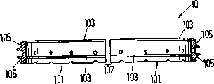
Fig. 2,3 and 4 illustrates the details that is positioned at uppermost brush ring 10 by Fig. 1, and it designs as the exemplary embodiments of sealing ring for stuffing box of the present invention.Fig. 2 illustrates the planimetric map of looking from the longitudinal axis A direction of above-mentioned brush ring 10, Fig. 3 illustrates the sectional view that passes through brush ring 10 along the hatching III-III of Fig. 2, Fig. 4 illustrates along the sectional drawing of the brush ring 10 of the hatching IV-IV of Fig. 2, and shows piston rod 3 so that understand content of the present invention better.
At the outer side surface of each ring section 101 two grooves 105 that all along the circumferential direction extend in each case are set and are used to accept spring 6 (see figure 1)s.In each case, above-mentioned groove 105 all can apply biasing force to brush ring 10 with respect to the spring that axial direction is arranged to it is accepted on the height that roughly is positioned at flange 103.
According to the present invention, the working surface 30 of brush ring 10 scribbles a kind of hard wear resistant coating 20.The Vickers hardness of this coating is at least 800HVI, and is made of than the low material of bulk material of making sealing ring for stuffing box abrasiveness, and in addition, coating 20 also has the very good characteristic of moving on the material of making piston rod 3.For the piston rod 3 that hardens on the main body (this is that current two-stroke large diesel machine is common), having proved chromium already and having contained the chromium pottery is the material that particularly suitable is made the coating 20 of working surface 30.Chrome coating preferably applies with galvanoplastic, and for example, working surface 30 is by galvanoplastic chromium plating securely.Proving already that the thickness of coating 20 was at least 0.3mm and is only effectively, is 0.3-0.7mm at the thickness of the exemplary embodiments floating coat 20 of this paper explanation.
Also available other the hard high-abrasive material that piston rod 3 is had a good roadability of coating 20 is made, and for example, stellite, Te Libo Laue alloy (tribaloy), nickel phosphor alloy or suitable material all are suitable for.Except above-mentioned galvanoplastic, can be coated with application layer 20 according to other appropriate method of used material selection, for example spraying method, plasma method or laser cladding method laser cladding method especially.
Specifically, all materials that are generally used for making the sealing ring for stuffing box in the two-stroke large diesel machine all are suitable for as the bulk material of making brush ring 10, for example: grey cast iron, steel, nonferrous materials such as leaded bronze, copper-aluminum alloy, copper-lead alloy and copper-tin alloy.
Make brush ring 10 or make respectively after the ring section 101 with bulk material, on its working surface 30, plate coating 20.
Because hard wear resistant coating 20 has been arranged.Brush ring 10 of the present invention has much more satisfied that therefore wearing valve has long operating life than existing sealing ring for stuffing box.In addition, owing to do not have hard particles to embed working surface 30, so fretting corrosion effect can not take place.The wear phenomenon of piston rod 3 also obviously alleviates.Moreover coating 20 can make brush ring 10 with higher specific surface pressure clamping piston bar 3, does not scratch and snap-in can not take place between working surface 30 and piston rod 3.Overall height H (comparing) by reducing working surface 30 and/or adopt the spring 6 of the stronger annular groove that places brush ring 10 105 can increase above-mentioned specific surface pressure with the brush ring of prior art.In above-mentioned exemplary embodiments, the specific surface pressure that brush ring 10 is pressed to piston rod 3 is at least 30N/cm
2This has just obviously improved the effect that brushes of brush ring 10.
Specifically, owing to obviously reduced wearing and tearing, so the radial width B of brush ring can be designed to more much smaller than the brush ring of prior art.The radial width B of brush ring 10 preferably equal at the most piston rod 3 diameter 7%, particularly advantageous be equal at the most piston rod 3 diameter 5%.After taking above-mentioned measure, except economical with materials, also having an advantage is more high resilience and be adapted to the profile of piston rod 3 more of brush ring 10, thus the effect that brushes that further increases brush ring 10.In addition, the elasticity of brush ring 10 makes it can only make two ring sections 101, and this just can reduce the number of locking part 102, and this also has positive role for reaching the high efficient that brushes.Another advantage of higher elasticity is, if consider that from circumference working surface 30 can apply more constant compression force, even still can keep than constant compression force when at work wearing and tearing taking place.
But obviously, sealing ring for stuffing box 10,11,12 of the present invention also can be made up of 3,4 or more a plurality of ring section.
On regard to explanation that the exemplary embodiments of the sealing ring for stuffing box of the present invention shown in Fig. 2-4 does and also have similarity for the sealing ring for stuffing box of the seal ring in the packing box of two-stroke large diesel machine 11 and brush oil ring 12 or other types.
Fig. 5 illustrates and the partial sectional view of Fig. 4 similar design as the exemplary embodiments of the seal ring 11 of sealing ring for stuffing box of the present invention.Label among the figure and top illustrated equivalent in meaning.In seal ring 11, the whole interface that radially inwardly represents forms the working surface 30 of coating 20.Because sealing ring 11 has excellent sealing performance, so be specially adapted to the large-scale diesel engine of under the condition of high scavenge pressure or suction pressure, working respectively.
With shown in Figure 4 similar, Fig. 6 illustrates the sectional view as the exemplary embodiments of the brush oil ring 12 in the sealing ring for stuffing box of the present invention, the meaning of number in the figure and top illustrated identical.In brush oil ring 12, in the mode that is similar to brush ring 10 two flanges 123 are set, its interface that radially inwardly represents constitutes the working surface 30 with coating 20 together.
At the packing box 1 that is used for two stroke crosshead large-scale diesel engines shown in Figure 1, whole sealing ring for stuffing box 10,11,12 all can design by the present invention.But the embodiment of packing box 1 also can have only the working surface 30 of one or several sealing ring for stuffing box to have coating 20.
Therefore, have hard and sealing ring for stuffing box 10,11,12 abrasion-resistant coating 20 according to the present invention proposes its working surface 30 that is used for two stroke crosshead large-scale diesel engines.Can apply higher specific surface pressure by this working surface.Sealing ring for stuffing box of the present invention has much better brushing property and sealing respectively than existing sealing ring for stuffing box, therefore significantly reduces the wearing and tearing between piston rod and the packing box and reduces oil consumption.
Claims (10)
1. sealing ring for stuffing box that is used for the packing box of two-stroke large diesel machine, described diesel engine has a plurality of cylinders, a piston that moves back and forth is set in this cylinder, this piston is connected with a crosshead by piston rod (3), above-mentioned packing box (1) is used for making piston rod (3) to pass it from suction chamber (4) and arrives crankshaft room (5), it is characterized in that the working surface (30) that slides along piston rod (3) in when work of above-mentioned sealing ring for stuffing box (10,11,12) has the hard and abrasion-resistant coating (20) of one deck.
2. according to the sealing ring for stuffing box of claim 1, it is characterized in that above-mentioned coating (20) is a kind of coating or a kind of ceramic coating that contains chromium of chromium.
3. according to the sealing ring for stuffing box of claim 1 or 2, it is characterized in that the working surface of above-mentioned ring (30) will carry out electroplated coating.
4. according to the sealing ring for stuffing box of claim 1 or 2, it is characterized in that above-mentioned coating (20) employing spraying method or plasma method or laser cladding method particularly laser cladding method are coated on the working surface (30).
5. according to the sealing ring for stuffing box of claim 1 or 2, it is characterized in that, contain at least two ring sections (101), this ring section (101) along the circumferential direction adjoins arrangement, and is complimentary to one another and constitute a ring (10,11,12).
6. according to the sealing ring for stuffing box of claim 1 or 2, it is characterized in that above-mentioned sealing ring for stuffing box is made up of two ring sections (101).
7. according to the sealing ring for stuffing box of claim 1 or 2, it is characterized in that the radial width of above-mentioned sealing ring for stuffing box (B) equals 7% of diameter of piston rod at the most, preferably, equal 5% of diameter of piston rod at the most.
8. according to the sealing ring for stuffing box of claim 1 or 2, it is characterized in that above-mentioned packing box contains a circumference that surrounds sealing ring for stuffing box (10,11,12) and sealing ring for stuffing box (10,11,12) is pressed onto spring (6) on the piston rod (3).
9. packing box (1) that is used for two stroke crosshead large-scale diesel engines, this packing box contain at least one by each sealing ring for stuffing box (10,11,12) in the aforesaid right requirement.
10. contain among the with good grounds claim 1-8 each sealing ring for stuffing box (10,11,12) or contain two stroke crosshead large-scale diesel engines of the packing box (1) of with good grounds claim 9.
Applications Claiming Priority (2)
| Application Number | Priority Date | Filing Date | Title |
|---|---|---|---|
| EP99810300.6 | 1999-04-12 | ||
| EP99810300 | 1999-04-12 |
Publications (2)
| Publication Number | Publication Date |
|---|---|
| CN1270288A CN1270288A (en) | 2000-10-18 |
| CN1216238C true CN1216238C (en) | 2005-08-24 |
Family
ID=8242764
Family Applications (1)
| Application Number | Title | Priority Date | Filing Date |
|---|---|---|---|
| CN001064665A Expired - Fee Related CN1216238C (en) | 1999-04-12 | 2000-04-11 | Sealing ring for stuffing box |
Country Status (8)
| Country | Link |
|---|---|
| EP (1) | EP1045175B1 (en) |
| JP (1) | JP2000291807A (en) |
| KR (1) | KR100679616B1 (en) |
| CN (1) | CN1216238C (en) |
| AT (1) | ATE344894T1 (en) |
| DE (1) | DE50013711D1 (en) |
| DK (1) | DK1045175T3 (en) |
| PL (1) | PL194501B1 (en) |
Families Citing this family (6)
| Publication number | Priority date | Publication date | Assignee | Title |
|---|---|---|---|---|
| DE10023846A1 (en) * | 2000-05-16 | 2001-11-22 | Federal Mogul Friedberg Gmbh | Stuffing box to seal piston rod in large diesel engine; has several metal rings arranged axially on top of each other and having lips on their inner surfaces that are pressed to seal piston rod |
| JP5173236B2 (en) * | 2007-04-10 | 2013-04-03 | 株式会社リケン | Stuffing box |
| DE102007030510A1 (en) * | 2007-06-30 | 2009-01-02 | Daimler Ag | Sealing device for high pressure applications |
| KR200449158Y1 (en) | 2008-05-16 | 2010-06-22 | 에스티엑스중공업 주식회사 | Stuffing Box for Piston Rod of 2-Stroke Engine |
| WO2013029612A1 (en) * | 2011-08-30 | 2013-03-07 | Man Diesel & Turbo | Method to reduce load to a sealing means circumfering a piston rod engine and such engine |
| CN104806375B (en) * | 2015-05-06 | 2018-01-30 | 江苏科技大学 | A kind of two-stroke cross-head diesel engine stuffing box device |
Family Cites Families (11)
| Publication number | Priority date | Publication date | Assignee | Title |
|---|---|---|---|---|
| DE2114152B2 (en) * | 1971-03-24 | 1975-06-12 | Maschinenfabrik Augsburg-Nuernberg Ag, 8900 Augsburg | Stuffing box seal for piston rods |
| JPS5569742A (en) * | 1978-11-20 | 1980-05-26 | Toyota Motor Corp | Piston ring for internal combustion engine |
| US4522412A (en) * | 1982-10-26 | 1985-06-11 | Keikoku Piston Ring Co., Ltd. | Oil ring with coil expander |
| CH660407A5 (en) * | 1983-08-25 | 1987-04-15 | Alfred F Schirmer | SEALING RING FOR PISTON RODS. |
| JPS61157670A (en) * | 1984-12-28 | 1986-07-17 | Teikoku Piston Ring Co Ltd | Sliding member |
| CH667312A5 (en) * | 1985-04-26 | 1988-09-30 | Sulzer Ag | IC engine piston rod seal rings - prevent flow of dirty oil into sump and fit in wall separating cylinder block from crankcase |
| JPH059567Y2 (en) * | 1986-11-28 | 1993-03-09 | ||
| US5015341A (en) * | 1988-08-05 | 1991-05-14 | Armco Steel Company, L.P. | Induction galvannealed electroplated steel strip |
| JPH0337477A (en) * | 1989-07-05 | 1991-02-18 | Riken Corp | Rubbing member |
| DE59005683D1 (en) * | 1990-01-22 | 1994-06-16 | Sulzer Innotec Ag | Coated metallic substrate. |
| JP3957778B2 (en) * | 1995-12-08 | 2007-08-15 | 株式会社リケン | Piston rod sealing device |
-
2000
- 2000-03-13 DE DE50013711T patent/DE50013711D1/en not_active Expired - Fee Related
- 2000-03-13 AT AT00810206T patent/ATE344894T1/en not_active IP Right Cessation
- 2000-03-13 EP EP00810206A patent/EP1045175B1/en not_active Expired - Lifetime
- 2000-03-13 DK DK00810206T patent/DK1045175T3/en active
- 2000-03-27 JP JP2000085888A patent/JP2000291807A/en active Pending
- 2000-04-10 KR KR1020000018568A patent/KR100679616B1/en not_active IP Right Cessation
- 2000-04-10 PL PL339539A patent/PL194501B1/en not_active IP Right Cessation
- 2000-04-11 CN CN001064665A patent/CN1216238C/en not_active Expired - Fee Related
Also Published As
| Publication number | Publication date |
|---|---|
| PL194501B1 (en) | 2007-06-29 |
| EP1045175B1 (en) | 2006-11-08 |
| EP1045175A1 (en) | 2000-10-18 |
| ATE344894T1 (en) | 2006-11-15 |
| DE50013711D1 (en) | 2006-12-21 |
| CN1270288A (en) | 2000-10-18 |
| JP2000291807A (en) | 2000-10-20 |
| DK1045175T3 (en) | 2007-02-19 |
| PL339539A1 (en) | 2000-10-23 |
| KR100679616B1 (en) | 2007-02-07 |
| KR20000077014A (en) | 2000-12-26 |
Similar Documents
| Publication | Publication Date | Title |
|---|---|---|
| EP1730396B1 (en) | High strength steel cylinder liner for diesel engine | |
| US7383807B2 (en) | Coated power cylinder components for diesel engines | |
| EP2045488B1 (en) | Piston ring of reciprocating engine | |
| RU2156370C1 (en) | Cylinder member such as cylinder liner, piston, piston skirt or piston ring in diesel engine, and piston ring for such engine | |
| WO2011154606A1 (en) | Cylinder liner of a reciprocating engine | |
| EP3163129B1 (en) | Piston ring | |
| US5392692A (en) | Antiblow-by piston and seal construction for high temperature applications | |
| CN1216238C (en) | Sealing ring for stuffing box | |
| US20040226402A1 (en) | Cylinders having differing surface roughness | |
| JP2007077988A (en) | Piston ring set | |
| CN1082159C (en) | Piston ring for combustion engines | |
| CN1112299C (en) | Oil lubricating seal device for ship tail shaft | |
| US11193447B2 (en) | Piston and cylinder of an internal combustion engine and internal combustion engine | |
| GB2153488A (en) | Nitrided steel piston ring | |
| EP0465022B1 (en) | Pistons | |
| US20240110625A1 (en) | Compression Ring | |
| CN215633376U (en) | Combined structure of piston and piston ring for improving sealing performance | |
| JP2004137955A (en) | Piston for internal combustion engine | |
| US12116951B2 (en) | Cylinder liner and cylinder bore | |
| RU2707798C2 (en) | Piston ring | |
| CN217501818U (en) | Piston ring group suitable for hydrogen internal combustion engine | |
| CN216111036U (en) | Piston ring and methanol engine | |
| CN2181582Y (en) | High pressure corrosion-resistant gear pump | |
| CN215213707U (en) | Step oil belt oil ring with DLC coating | |
| CN210033651U (en) | Steel trapezoidal piston ring |
Legal Events
| Date | Code | Title | Description |
|---|---|---|---|
| C06 | Publication | ||
| PB01 | Publication | ||
| C53 | Correction of patent of invention or patent application | ||
| COR | Change of bibliographic data |
Free format text: CORRECT: APPLICANT; FROM: WARTSILA NSD SCHWEIZ AG TO: WATEXILA SWITZERLAND LTD. |
|
| CP02 | Change in the address of a patent holder |
Address after: Winterthur Switzerland Applicant after: Wartsila Schweiz AG Address before: Winterthur Switzerland Applicant before: New Sulzer Diesel A G |
|
| C10 | Entry into substantive examination | ||
| SE01 | Entry into force of request for substantive examination | ||
| C14 | Grant of patent or utility model | ||
| GR01 | Patent grant | ||
| C17 | Cessation of patent right | ||
| CF01 | Termination of patent right due to non-payment of annual fee |
Granted publication date: 20050824 Termination date: 20100411 |