CN1207603C - Optical system and equipment for multi-beam scan and imaging device - Google Patents
Optical system and equipment for multi-beam scan and imaging device Download PDFInfo
- Publication number
- CN1207603C CN1207603C CNB011450665A CN01145066A CN1207603C CN 1207603 C CN1207603 C CN 1207603C CN B011450665 A CNB011450665 A CN B011450665A CN 01145066 A CN01145066 A CN 01145066A CN 1207603 C CN1207603 C CN 1207603C
- Authority
- CN
- China
- Prior art keywords
- optical system
- lens
- relay optical
- collector lens
- light beam
- Prior art date
- Legal status (The legal status is an assumption and is not a legal conclusion. Google has not performed a legal analysis and makes no representation as to the accuracy of the status listed.)
- Expired - Fee Related
Links
Images


Classifications
-
- G—PHYSICS
- G02—OPTICS
- G02B—OPTICAL ELEMENTS, SYSTEMS OR APPARATUS
- G02B26/00—Optical devices or arrangements for the control of light using movable or deformable optical elements
- G02B26/08—Optical devices or arrangements for the control of light using movable or deformable optical elements for controlling the direction of light
- G02B26/10—Scanning systems
- G02B26/12—Scanning systems using multifaceted mirrors
- G02B26/123—Multibeam scanners, e.g. using multiple light sources or beam splitters
Abstract
A multi-beam light scanning optical system has a light beam incident optical system for causing a condenser lens to condense each of light beams emitted from a plurality of light sources and making the light beams incident on a deflecting surface of an optical deflector. In the light beam incident optical system, a relay optical system is inserted between the plurality of light sources and the condenser lens. An aperture stop for limiting a beam width of each of the light beams emitted from the plurality of light sources is arranged on a light source side with respect to an image forming point of each of the plurality of light sources through the relay optical system.
Description
Technical field
The present invention relates to the imaging device of a kind of photoscanning optical system and this system of use, and the photoscanning optical system and the photoscanning optical device that are used for laser beam printer or digital copier, more particularly, relate to use a plurality of light sources as light source with multiple beam scanning optics that obtains high speed operation and high record density and the imaging device that uses this multiple beam scanning optics.
Background technology
Fig. 9 represents that one uses the main sweep part of traditional multiple beam scanning optics of a plurality of light sources.A plurality of light sources 21 are made up of the semiconductor laser with a plurality of luminous points.Every the collimated lens 22 of light beam that send from a plurality of light sources convert substantially parallel light beam or convergent beam to.Every light beam forms required cross sectional shape and assembles in inferior direction of scanning through 24 of cylindrical lenses through an aperture diaphragm 23, so that form near the deflection/reflecting surface 25a as the polygonal mirror 25 of optical deflector resembling picture that focal line grows on the main scanning direction.Polygonal mirror 25 rotates along the direction shown in the arrow A among Fig. 9 with predetermined speed, every light beam by polygonal mirror 25 reflection/deflections and scanning, be focused on the surface of forming by photosensitive drums etc. to be scanned 27 (scanning plane 27) by f-θ lens 26, become a hot spot, and light beam scans with predetermined speed direction of arrow B in Fig. 9.One BD optical system 28 is surveyed and is write the starting position.This BD optical system 28 comprises a BD slit 28a, BD lens 28b and BD sensor (sync bit detecting element) 28c.
In such multiple beam scanning optics, as shown in figure 10, if a plurality of light source is then much bigger than recording density at interval at this scanning plane last scan line along inferior direction of scanning arranged perpendicular.For fear of this situation, usually, a plurality of as shown in figure 11 light sources are tilted configuration, and adjust angle of inclination δ and accurately adjust inferior scan line spacings on the scanning plane whereby so that and recording density mate.
In having traditional photoscanning optical system of said structure, a plurality of light sources are tilted configuration.Therefore, because the reflecting surface position that the light beam arrival of sending from a plurality of light sources departs from the polygonal mirror of main scanning direction, and by polygonal mirror with the reflection of different reflection angle, thereby form hot spot, (light beam A and light beam B) as shown in figure 12 departing from the scanning plane position of main scanning direction.
Therefore, in such multiple beam scanning optics, view data is sent out with predetermined δ T time delay, so that from the image space of the light beam of light source and location matches from light beam imaging on this scan target surface of specific reference light source.
With the time delay of δ T, the polygonal mirror surface with the angle with respect to δ T time delay be set to surface 25 '.At this moment, light beam is reflected in B ' direction, promptly with light beam A in the same way so that the hot spot image space of two light beams coupling.
Suppose for a certain reason.(for example, the site error between the optical unit of scanning of a surface and support of optical system, rigging error when assembling the optical module in the optical unit or the like) focusing error occurs at main scanning direction.In this case, when scanning of a surface 27 is displaced to as shown in figure 12 27 ' time of position, the image space of every light beam is offset δ Y on main scanning direction.
Routinely, when as mentioned above from the image space skew of every light beam of a plurality of light sources, printing precision descends, and image quality decrease.
Because various factors causes the focus bias/error on main scanning direction, and they can not be eliminated fully.Even to the many expenses of the process need of its adjustment.At present, consider that one uses the optical system of plastics through being often used as f-θ lens for expense.Produce a plastic lens by injection moulding, and its surface accuracy is lower than the precision that obtains by the polishing of optical glass elements.Especially, a plastic lens is easy to certain a part of protruding error that produces with respect to design load at camera lens, and produces recessed error at another part.Because the focal shift that causes of these surface accuracy errors can not be corrected during by scan target surface.
Therefore be difficult to correct because the image quality decrease that skew causes from the image space between the light beam of a plurality of light sources.
As mentioned above, for for simplicity, the quantity of luminous point is 2.Obviously, when the luminous point number increases to 3,4,5,6 ... the time, the value δ Y that results from two terminal light sources increases pro rata.Promptly in traditional multiple beam scanning optics, thereby even be increased to obtain high-speed cruising the time when the luminous point number, printing precision also descends, and is offset increase and causes image quality decrease from the image space between the light beam of a plurality of light sources because of above-mentioned, causes being difficult to obtain high speed operation.
Summary of the invention
The present invention is used to address the above problem, its objective is by relay optical system is set between a plurality of light sources and a collector lens provides one can optimize the multiple beam scanning optics of obtaining high speed operation and high image quality, make and move and to be prevented effectively from any image space between the light beam of a plurality of light sources, and need not any complicated adjusting, the present invention also aims to provide the imaging device that uses this multiple beam scanning optics.
According to this invention, (1) a kind of multiple beam scanning optics is provided, have: optical deflector; And light beam incident optical system, be used to make collector lens to assemble each the bar light beam that sends from a plurality of light sources, and described light beam is incided on the deflection plane of described optical deflector, wherein in described light beam incident optical system, relay optical system is inserted between described a plurality of light source and the described collector lens
Wherein each described light source on main sweep face the imaging point by described relay optical system between described optical deflector and described relay optical system,
Aperture diaphragm is arranged on light source one side with respect to described imaging point, and wherein said aperture diaphragm is used to limit the width of every the light beam that sends from described a plurality of light sources.
Particularly, in this system, (1-1) collector lens is arranged to make this aperture diaphragm to conjugate to the deflection plane of this optical deflector basically, (1-2) establishes f
2Be the focal length of this relay optical system, d is the distance of relay optical system posterior principal point to aperture diaphragm, then satisfies following formula:
0.75≤f
2/d≤3.0 (1)
(1-3) a plurality of light sources are separated on main scanning direction at least, (1-4) establish f
1Be the focal length of collector lens, f
2Be the focal length of relay optical system, then satisfy following formula:
0.2≤f
2/f
1≤1.0 (2)
(1-5) this relay optical system (1-6) is established β to be no more than the picture that one to one size forms a plurality of light sources
2, be the imaging magnification of relay optical system, then satisfy following formula:
0.25≤β
2≤1.0 (3)
The spherical aberration that (1-7) produces in the relay optical system is eliminated by collector lens, the curvature of field that (1-8) produces in the relay optical system is eliminated by collector lens, (1-9) relay optical system has single cellular construction, (1-10) collector lens has two concavees lens and convex lens that are arranged in order from light source side, and (1-11) relay optical system has two identical shaped convex lens.
According to the present invention, (2) a kind of multiple beam scanning optics also is provided, it has the light beam incident optical system, is used to make collector lens to assemble the light beam that each bar sends from a plurality of light sources that separate at main scanning direction at least, and this light beam is incided on the deflection plane of optical deflector; Wherein in this light beam incident optical system, relay optical system is inserted between a plurality of light sources and the collector lens, and be used to limit the aperture diaphragm of the width of light beam of every the light beam that sends from a plurality of light sources, be arranged on light source one side with respect to the imaging point of each light source by relay optical system, wherein said imaging point is between described collector lens and described optical relay system; This collector lens makes this aperture diaphragm conjugate to the deflector surface of optical deflector basically; This relay optical system forms the picture of a plurality of light sources to be no more than one to one size, and establishes f
1Be the focal length of collector lens, f
2Be the focal length of relay optical system, β
2Be the imaging magnification of relay optical system, d is the distance of relay optical system posterior principal point to collector lens, then satisfies following condition:
0.75≤f
2/d≤3.0 (1)
0.2≤f
2/f
1≤1.0 (2)
0.25≤β
2≤1.0 (3)
Particularly, in this system, the spherical aberration that (2-1) produces in the relay optical system is eliminated by collector lens, the curvature of field that (2-2) produces in the relay optical system is eliminated by collector lens, (2-3) relay optical system has single cellular construction, (2-4) collector lens has two concavees lens and convex lens that are arranged in order from light source side, and (2-5) relay optical system has two identical shaped convex lens.
In addition, according to the present invention, (3) a kind of multiple beam scanning optics is provided, it has the light beam incident optical system, be used to make collector lens to assemble the light beam that each bar sends from a plurality of light sources that separate at main scanning direction at least, and this light beam is incided on the deflection plane of optical deflector; Wherein in the light beam incident optical system, relay optical system is inserted between a plurality of light sources and the collector lens; Be used to limit the aperture diaphragm of the width of light beam of every the light beam that sends from a plurality of light sources, be arranged on light source one side with respect to the imaging point of each light source by relay optical system; This collector lens makes aperture diaphragm conjugate to the deflector surface of optical deflector basically; This relay optical system is to be no more than the picture that one to one size forms a plurality of light sources; If f
1Be the focal length of this collector lens, f
2Be the focal length of relay optical system, β
2Be the imaging magnification of relay optical system, d is the distance of relay optical system posterior principal point to collector lens, then satisfies following condition:
0.75≤f
2/d≤3.0 (1)
0.2≤f
2/f
1≤1.0 (2)
0.25≤β
2≤1.0 (3)
And the spherical aberration and the curvature of field that produce in the relay optical system are eliminated by collector lens.
Particularly, in this system, (3-1) relay optical system has single cellular construction, and (3-2) collector lens has two concavees lens and convex lens that are arranged in order from light source side, and (3-3) relay optical system has two identical shaped convex lens.
According to the present invention, (4) a kind of multi-beam optical scanning device also is provided, it uses by above-mentioned (1), (1-1) to (1-10), (2), (2-1) to (2-5), (3) and (3-1) arrive the multi-beam scanning apparatus of (3-3) described multiple beam scanning optics.
According to the present invention, (5) a kind of imaging device is provided, it comprises: the multi-beam optical scanning device described in above-mentioned (4); Be arranged on lip-deep photosensitive-member to be scanned; Developer is used for the electrostatic latent image that is formed on photosensitive-member by every light beam of multiple beam scanning optical device scan is developed, and makes it to become toner image; The toner image that is used for being developed is transferred to the transfer device on the transfer member; And the fixing device that the toner image that is transferred on the transfer member is carried out photographic fixing.
(6) a kind of imaging device also is provided, comprises (a 4) described multi-beam optical scanning device and a printing machine controller, the code data that is used for receiving from external unit is converted to picture signal, and exports this picture signal to multi-beam optical scanning device.
Description of drawings
Fig. 1 is a sectional view, and expression is according to the multiple beam scanning optics of the first embodiment of the invention major part at main scanning direction;
Fig. 2 A, 2B and 2C are the views of the light beam incident optical system in the expression multiple beam scanning optics, in order to the effect of explanation first embodiment of the invention;
Fig. 3 is a sectional view, and expression is according to the multiple beam scanning optics main sweep cross section of first embodiment of the invention;
Fig. 4 is the view that is used to illustrate according to the multiple beam scanning optics main sweep cross section structure of first embodiment of the invention;
Fig. 5 represents the spherical aberration and the curvature of field curve of generation in the relay lens 2;
Fig. 6 represents the spherical aberration and the curvature of field curve of generation in the collector lens 3;
Fig. 7 represents the spherical aberration and the curvature of field curve that produce in the whole incident optical system that relay lens 2 and collector lens 3 form;
Fig. 8 is a sectional view, and expression is according to the multiple beam scanning optics of the second embodiment of the invention major part at main scanning direction;
Fig. 9 is the view that is used for interpretation routine multiple beam scanning optics;
Figure 10 is the view of light luminous point layout in the conventional multiple beam scanning optics of expression;
Figure 11 is the view of another layout of luminous point in the conventional multiple beam scanning optics of expression;
Figure 12 is the view of focal shift in the interpretation routine multiple beam scanning optics, and;
Figure 13 is a sectional view, and expression is according to the imaging device of the embodiment of the invention major part in inferior direction of scanning.
Embodiment
Fig. 1 is that it is applied to imaging device, as laser printer and digital copy machine according to the multiple beam scanning optics of the first embodiment of the invention sectional view in the major part of main scanning direction.
Referring to Fig. 1, light source 1 is formed by the semiconductor laser with a plurality of luminous points, and wherein a plurality of light sources are tilted configuration, and inclination angle δ is adjusted, as shown in figure 11, with the inferior trace interval on the accurate adjustment scanning of a surface (surface that will be scanned), so that mate with recording density.For the ease of understanding, although the number of luminous point is 2 in first embodiment, above-mentioned thought is equally applicable to the situation of the number increase of luminous point.
By the relay lens 2 as relay optical system, every the light beam that sends from luminous point images in a P.Every the light beam that images in a P is converted into substantially parallel light beam, divergent beams or convergent beam by collector lens 3, and assemble in inferior direction of scanning by 4 of cylindrical lenses, make as being that picture the focal line is formed near deflection/reflecting surface as the polygonal mirror 5 of optical deflector along main scanning direction.Cylindrical lens 4 comprises first cylindrical lens of being made by glass with convex surface focal power and second cylindrical lens that is made of plastics with concave light focal power.Cylindrical lens 4 is corrected because the inferior swept-focus as the f-θ lens 7 that are made of plastics of scanning optics that environmental change causes moves.
Each width of light beam that aperture diaphragm 6 restricted passage relay lenss 2 are assembled.
Every the light beam that is also scanned by polygonal mirror 5 refraction/reflection of rotating with a predetermined speed by arrow A direction indication among Fig. 1 is focused, by f-θ lens 7 as scanning optics, on scanning of a surface 8, form hot spot, this surface 8 is made up of the thing of photosensitive drums and so on, and described light beam scans with predetermined speed direction of arrow B in Fig. 1.
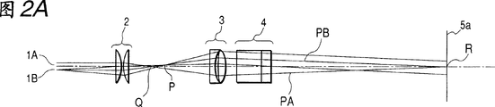
Light beam incident optical system in the multiple beam scanning optics, below with reference to Fig. 2 A, 2B and 2C are described in detail.
Fig. 2 A is a sectional view, and the main sweep cross section of the light beam incident optical system in the expression multiple beam scanning optics is with the effect of explanation first embodiment of the invention.Fig. 2 B is the sectional view of expression time scanning cross-section.With reference to figure 2A and 2B, this structure does not comprise aperture diaphragm 6, does not contain the situation of aperture diaphragm 6 with explanation.
As mentioned above, contain two luminous point 1A and 1B in the light source 1 that is formed by semiconductor laser, these a plurality of light sources are tilted configuration, as shown in figure 11, inclination angle δ is adjusted, accurately to be adjusted at the inferior trace interval on the scanning target face, so that matched record density.Here, the luminous point number is set as 2.But the present invention is not limited to this, and can to adapt to the luminous point number very effectively be 3 or more situation.Below describe and to suppose that semiconductor laser is used as light source.But the present invention also is not limited to this, and any other light source such as LED can be used as light source.
Every the light beam that sends from two luminous point 1A and 1B images in a P by the relay lens 2 as relay optical system.Every the light beam that images in a P is converted to substantially parallel light beam by collector lens 3, convergent beam or divergent beams, and assemble in inferior direction of scanning by 4 of cylindrical lenses, make as being that image the focal line is formed near the refraction/reflection surface 5a as the polygonal mirror 5 of optical deflector along main scanning direction.
Consider the chief ray PA and the PB of the light beam that two luminous point 1A and 1B send.When two chief rays all were parallel to light beam incident optical system optical axis AX and are issued, two chief ray PA and PB met at the back focus Q of relay optical system.
In the light beam incident optical system of said structure, with reference to prior art shown in Figure 12, because main sweep image space deviation δ Y can be eliminated between two light beams that the focal shift of main scanning direction causes.Obviously, since the light beam A of Figure 12 and B ' separate the image space deviation δ Y that has produced at main scanning direction at main scanning direction.
In the first embodiment of the present invention, because the light beam incident optical system is so designed, make to arrive same point R on the 5a of refraction/reflection surface at two chief ray PA of main scanning direction and PB, identical with light beam PB ' track among Figure 12 corresponding to light beam B corresponding to the light beam PA of light beam A.Therefore, in theory between two of prior art light beams since the main sweep image space deviation δ Y that the focal shift on main scanning direction causes can not occur.
Then, suppose that the chief ray PA of the light beam that two luminous point 1A and 1B send and PB are not parallel to light beam incident optical system optical axis AX.Light beam from semiconductor laser is parallel to light beam incident optical system optical axis AX in theory, but generally has some angle errors.Although it has slight variation being parallel and perpendicular between the direction on disturbance plane, this approximately ± 2 ° to ± 3 ° angle error must be considered.
Suppose to have only among two chief ray PA and the PB chief ray PA to be not parallel to light beam incident optical system optical axis AX.Fig. 2 C is when having only chief ray PA to be not parallel to light beam incident optical system optical axis AX among two chief ray PA and the PB, the sectional view in the main sweep cross section of the light beam incident optical system in the multiple beam scanning optics.Referring to Fig. 2 C, when main scanning direction formed angle α, this light beam did not pass through light beam incident optical system optical axis AX at Q point from the chief ray PA of luminous point 1A emission.The position that chief ray PA passes through is split up into Δ 1=f at the Q point place and the optical axis AX of main scanning direction
2* tan α.On the 5a of refraction/reflection surface, the chief ray PA point of arrival is Δ 2=Δ 1 * β apart from light beam incident optical system optical axis AX on main scanning direction
1, promptly multiply by the imaging magnification β of collector lens 3 by value Δ 1
1The value that obtains.In this case, because two chief ray PA and PB do not arrive the same point R on the 5a of refraction/reflection surface, so main sweep image space deviation δ Y will produce between two light beams that cause owing to above-mentioned focal shift at main scanning direction.As mentioned above, such angle error can't be eliminated fully.That is, when designing relaying lens 2 and collector lens 3 resemble the first embodiment of the present invention, be difficult to eliminate at the image space deviation δ of main scanning direction Y.
First implements, and is used to limit the aperture diaphragm 6 of the width of light beam of every the light beam that sends from a plurality of light sources, is configured in light source one side about respective imaging by the light beam that passes through relay optical system from a many light source of P.
Fig. 3 is a sectional view, and expression is according to the main sweep part of the light beam incident optical system of first embodiment of the invention, and wherein aperture diaphragm 6 is positioned at the Q point on the light beam incident optical system optical axis AX.Fig. 3 represents such situation, wherein has only the PA among two chief ray PA and the PB to be not parallel to light beam incident optical system optical axis AX, shown in Fig. 2 C.
Referring to Fig. 3, the width with chief ray PA main scanning direction formation α angle that send from luminous point 1A is limited by aperture diaphragm 6, makes this chief ray PA intersect at a Q and light beam incident optical system optical axis AX, and is the same with the chief ray PB that sends from luminous point 1B.Therefore, the R point on the deflection/reflecting surface 5a after two chief ray PA that intersect at a Q and PB are seeing through condenser 3 is crossing once more.
In other words: in the first embodiment of the present invention, be used to limit the aperture diaphragm 6 of the width of light beam of each the bar light beam that sends from a plurality of light sources, be placed in the some Q of light source side with respect to a plurality of light sources by imaging point P as the relay lens 2 of relay optical system.With this set, even two chief ray PA of the light beam that sends from two luminous point 1A and 1B and the optical axis AX that PB is not parallel to the light beam incident optical system, this two chief ray still meets at some R on deflection/reflecting surface 5a by condenser 3.Therefore, since on the above-mentioned main scanning direction between two light beams that cause of focal shift main sweep imaging point skew δ Y can be eliminated.
With this set, even the light beam that light source sends has angular variation, the reduction of any printing precision and decrease in image quality can prevent effectively by eliminating main sweep image space skew δ Y.In addition, when using cheap plastic lens as the f-θ lens of scanning optics, the main sweep image space skew δ Y that is caused by the focal shift of f-θ lens can be eliminated.Therefore, one can use inexpensive structure, and multiple beam scanning optics and the imaging device of exporting the high quality graphic that does not have printing precision reduction and image quality decrease can be obtained.
When the light beam incident optical system when as in the first embodiment of the invention, forming as relay lens 2, collector lens 3 and the aperture diaphragm 6 of relay optical system, its size will be the same with conventional incident optical system huge.In order to prevent the increase of virtually any size, in the first embodiment of the present invention, as the focal distance f of the relay lens 2 of relay optical system
2, the image magnification ratio β of relay lens 2
2, the focal distance f of condenser 3
1, the posterior principal point of relay optical system to aperture diaphragm 6 apart from d etc. by suitable setting, therefore obtain compact structure effectively.
These will be below with reference to figure 4 explanations.Fig. 4 is the sectional view according to the main sweep of the light beam incident optical system of first embodiment of the invention part, and wherein aperture diaphragm 6 is positioned at the some Q on the optical axis AX of light beam incident optical system, as shown in Figure 3.The a plurality of light sources that form from semiconductor laser comprise luminous point 1A and 1B respectively.If f
2Be the focal length of relay lens 2, β
2Be the image magnification ratio of relay lens 2, f
1Be the focal length of condenser 3, d is as the posterior principal point of the relay lens 2 of the relay optical system distance to aperture diaphragm 6, S
1Be the posterior principal point of condenser 3 distance, S to deflection/reflecting surface 5a
KBe the distance of aperture diaphragm 6 to the front principal point of condenser 3, Δ is that aperture diaphragm arrives the distance of a plurality of light sources by the imaging point P of relay lens 2,
1Be the diaphragm diameter of aperture diaphragm 6,
0Be the beam diameter (system) of every light beam seeing through from condenser 3, Fn1 is the F number of image one side of each light beam by relay lens 2, and it is determined by aperture diaphragm 6, and L is the distance from the luminous point 1A of a plurality of light sources and 1B to deflection/reflecting surface 5a.Suppose that from every light beam that condenser 3 sees through be substantially parallel light beam.
In this case, the distance L from the luminous point 1A of a plurality of light sources and 1B to deflection/reflecting surface 5a is provided by following formula:
L=(2+β
2+1/β
2)×f
2+f
1
Be minimizing value L, that is, and for making the incident optical system compactness, value f
1And f
2Can be reduced value β
2Be set as 1.In this case, visibility L is a minimum value.The focal distance f of relay lens
2With the collector lens focal distance f
1The ratio that influences of L of adjusting the distance is f
2: f
1=4: 1, as following formula, that is: when
f
2/f
1=1/4
Or littler, β
2=1, value L can be reduced effectively.
But, if value f
2With respect to f
1By being established too smallly, then the spherical aberration and the curvature of field that produces as the relay lens 2 of relay optical system becomes big.For program for correcting phase difference satisfactorily, value f
2Should be with respect to f
1Established more greatly.But, if value f
2By established f
1Excessive, then be worth L can not be established little, thereby incident optical system can't be compact.In the first embodiment of the present invention, value f
1And f
2Satisfy:
0.2≤f
2/f
1≤1.0 (2)
The diaphragm diameter of aperture diaphragm 6
1Provide by following formula:
1≤Δ/Fn1
From the following formula relation as can be seen, the diaphragm diameter of aperture diaphragm 6
1Determine by value Δ and Fn1.The value Δ is by value S
1, S
kAnd f
1Determine.When collector lens was configured in general position, this value Δ was generally less relatively.At this moment, if value Fn1 is big, the diaphragm diameter of aperture diaphragm 6 then
1Diminish.For example, as the diaphragm diameter of aperture diaphragm 6
1When having id tolerance, then the variation owing to spot diameter on the id tolerance scanning of a surface becomes big, is difficult to obtain stable spot diameter.In order to reduce the influence of id tolerance, Fn1 is preferably little for value.This can by make relay lens 2 as relay optical system form one to one or the image of littler a plurality of light sources realize.But if image magnification ratio is too reduced, then the coupling efficiency of the light beam of the light source by relay lens 2 can descend undesirablely.Therefore, in the first embodiment of the present invention, the image magnification ratio β of relay lens 2
2Should satisfy:
0.25≤β
2≤1.0 (3)
Best in the ideal case aperture diaphragm 6 is set at the back focus place as the relay lens 2 of relay optical system.But such layout is impossible exist in some cases, because the mechanical constraint of the integral body arrangement of incident optical system and contrast layout.At this moment, the position of aperture diaphragm 6 can be changed in the scope of the skew of main sweep image space between two light beams δ Y amount permission suitably.Therefore, in the first embodiment of the present invention, allow f
2Be the focal length of relay optical system, d is the distance of the posterior principal point of relay optical system to aperture diaphragm 6, and then following condition is satisfied:
0.75≤f
2/d≤3.0 (1)
If aperture diaphragm 6 disposes like this, make value " f/d " be lower than the lower limit of condition (1), then aperture diaphragm 6 is just too near from collector lens 3, and diaphragm diameter
1Must be little.As mentioned above, if the diaphragm diameter of aperture diaphragm 6
1When having id tolerance, then the variation of the spot diameter on the scanning of a surface strengthens, and this is difficult to obtain stable spot diameter.On the contrary, if aperture diaphragm 6 disposes like this, " the f of the value of making
2/ d " surpass the upper limit of condition (1), then main sweep image space skew δ Y amount will be above permissible value between two light beams, and since in each light beam the asymmetric light intensity imaging performance that causes that distributes descend, the light quantity difference change on the scanning of a surface between two light beams is greatly.
As the feature of first embodiment of the invention, in order to constitute compact incident optical system, relay optical system has a cellular construction, and is offset by the spherical aberration and the curvature of field that collector lens 3 produces by the spherical aberration and the curvature of field that relay optical system produces.
As described in relation (2) and (3), as the focal distance f of the relay lens of relay optical system
2Need little arriving to a certain degree, and the image magnification ratio of relay lens 2 is made as preferably also negative.In addition, preferably each in relay lens 2 and the collector lens 3 has a spot of assembly, and is set to compactness.But, be difficult to correct the spherical aberration and the curvature of field that produces in the relay lens 2, also can not design relay lens 2 is the two-lens structure of few components.
In the first embodiment of the present invention, relay lens 2 is made up of two identical lens of shape, and the spherical aberration that produces in this relay lens and the curvature of field are offset by collector lens 3.
The spherical aberration and the curvature of field that relay lens 2 produces are all very little.The spherical aberration that these are little and the curvature of field are by to form collector lens 3 and eliminate with optimizing lens arrangement.More particularly, collector lens 3 has two lens, i.e. recessed the and convex lens that set gradually from light source side.With this lens arrangement, the spherical aberration that collector lens 3 generations are big and the curvature of field are to offset the little spherical aberration and the curvature of field that relay lens 2 produces.
In the first embodiment of the present invention, this arrangement makes might use relay lens 2 and the collector lens 3 with few components, makes the incident optical system compactness, and can proofread and correct the spherical aberration and the curvature of field of whole incidence system satisfactorily.Therefore, the light spot shape on the scanning of a surface also can be proofreaied and correct well, can be corrected fully for a short time at the relative deviation corresponding to the hot spot imaging performance between the light beam of a plurality of light sources.As a result, one can have cheap cramped construction, and multiple beam scanning optics and the imaging device of exporting the high quality graphic that does not have printing precision reduction and image quality decrease can be obtained.
The situation that is furnished with a plurality of light sources as shown in figure 11 has been described in the above.When the combined focal length of relaying lens 2 and collector lens 3 is longer than the focal length of collimation lens 22 of conventional structure shown in Figure 9, when a plurality of light source is set, be reduced as shown in figure 10 in the inferior sweep spacing between the light beam sweep trace on the scanning of a surface.Promptly, because can be used in from the inferior sweep test of the very near part of the optical axis of each optical system of scanning optics from each light beams of a plurality of light emitted, so can be reduced corresponding to the imaging performance relative deviation between the light beam of a plurality of light sources, high-quality image can be output.
Table 1 expression is according to the characteristic of the multiple beam scanning optics of first embodiment of the invention.
When the intersection point of establishing each lens surface and optical axis is initial point, the direction of optical axis is made as X-axis, axle vertical with optical axis in the main sweep cross section is made as Y-axis, and vertical with optical axis axle is made as the Z axle in inferior scanning cross-section, and then the aspherical shape as the main sweep part of the f-θ lens of scanning lens is:
Wherein R is a radius-of-curvature, k, B
4To B
10Be asphericity coefficient.
If each coefficient is according to the positive and negative variation of value Y, using the coefficient of band suffix u when the Y value for timing is ku and B
4uTo B
10u, when Y uses coefficient k l and the B of band suffix l when negative
4lTo B
10l
According to the shape of inferior scanning cross-section, establishing y is the coordinate of lens surface along main scanning direction, and radius-of-curvature r ' is given as follows:
r′=r(l+D
2Y
2+D
4Y
4+D
6Y
6+D
8Y
8+D
10Y
10)
Wherein r is a radius-of-curvature, D
2To D
10It is coefficient.
If each coefficient is according to the positive and negative variation of value Y, when Y is timing, radius-of-curvature r ' is D by the coefficient of band suffix u
2uTo D
10uCalculate; When Y when negative, radius-of-curvature r ' is D by the coefficient of band suffix l
2lTo D
10lCalculate.
Table 2 expression value f
1, f
2, β
2With d and respective conditions (1) eigenwert to (3).Can find out that from table all these values all satisfy above condition.
Table 1
| Use wavelength | λ(nm) | 780 |
| Luminous counting | n | 2 |
| Luminous point at interval | 1 | 0.0900 |
| Light source configuration pitch angle | δ | 2.9727 |
| Light source is to the first surface of relay lens | d0 | 17.5665 |
| The radius-of-curvature of the first surface of first relay lens | R1 | -1678.5394 |
| The thickness of first relay lens | d1 | 1.6249 |
| The radius-of-curvature of the second surface of first relay lens | R2 | -10.2985 |
| The second surface of first relay lens is to the first surface of second relay lens | d2 | 0.8126 |
| The radius-of-curvature of the first surface of second relay lens | R3 | 10.2985 |
| The thickness of second relay lens | d3 | 1.6249 |
| The radius-of-curvature of the second surface of second relay lens | R4 | 1678.8334 |
| The second surface of second relay lens is to aperture diaphragm | d4 | 5.6744 |
| Aperture diaphragm is to the source imaging point | d5 | 4.1070 |
| Source imaging is o'clock to the first collector lens first surface | d6 | 14.1901 |
| The radius-of-curvature of the first collector lens first surface | R7 | 98.5509 |
| The first collector lens thickness | d7 | 2.0000 |
| The radius-of-curvature of the first collector lens second surface | R8 | 16.1422 |
| The first collector lens second surface is to the second collector lens first surface | d8 | 1.0000 |
| The radius-of-curvature of the second collector lens first surface | R9 | 79.9074 |
| The second collector lens thickness | d9 | 2.0000 |
| The radius-of-curvature of the second collector lens second surface | R10 | -10.9761 |
| Second collector lens is to the first cylindrical lens first surface | d10 | 3.0130 |
(continued)
Table 1 (continuous table)
| Time scanning radius-of-curvature of the first cylindrical lens first surface | Rs11 | 28.6850 |
| The first cylindrical lens thickness | d11 | 7.0000 |
| Time scanning radius-of-curvature of the first cylindrical lens second surface | Rs12 | 0.0000 |
| The first cylindrical lens second surface is to the second cylindrical lens first surface | d12 | 0.3110 |
| Time scanning radius-of-curvature of the second cylindrical lens first surface | Rs13 | -53.3330 |
| The second cylindrical lens thickness | d13 | 3.0000 |
| Time scanning radius-of-curvature of the second cylindrical lens second surface | Rs14 | 0.0000 |
| The second cylindrical lens second surface is to polygonal mirror refraction/reflection surface | d14 | 83.3600 |
| Polygonal mirror refraction/reflection surface to a f-θ lens first surface | d15 | 41.7767 |
| The one f-θ lens thickness | d16 | 9.5000 |
| The one f-θ lens second surface to the two f-θ lens first surfaces | d17 | 7.1362 |
| The 2nd f-θ lens thickness | d18 | 8.6000 |
| The 2nd f-θ lens second surface is to the scanning target surface | d19 | 189.7396 |
| The first relay lens refractive index | n1 | 1.7620 |
| The second relay lens refractive index | n2 | 1.7620 |
| The first collector lens refractive index | n3 | 1.5107 |
| The second collector lens refractive index | n4 | 1.7620 |
| The first cylindrical lens refractive index | n5 | 1.5107 |
| The refractive index of second cylindrical lens | n6 | 1.4910 |
| The refractive index of the one f-θ lens | n7 | 1.5242 |
| The refractive index of the 2nd f-θ lens | n8 | 1.5242 |
| The polygonal mirror incident angle of incident optical system | α | 60.0000 |
| The maximum emergence angle of polygonal mirror | θmax | 41.3468 |
| Polygonal mirror circumscribed circle diameter 50 hexagons | ||
(continued)
Table 1 (continuous table)
| F-θ lens shape | |||
| The one f-θ lens | |||
| First surface | Second surface | ||
| R | -67.970 | R | -49.663 |
| k | -5.593E-01 | Ku | 3.780E-02 |
| B 4 | 1.106E-06 | B 4u | 1.207E-6 |
| B 6 | 5.551-11 | B 6u | 8.041E-10 |
| B 8 | 0.000E+00 | B 8u | -3.000E-13 |
| B 10 | 0.000E+00 | B 10u | 1.631E-16 |
| kl | 2.867E-02 | ||
| B 4l | 1.156E-06 | ||
| B 6l | 8.466E-10 | ||
| B 8l | -3.165E-13 | ||
| B 10l | 1.631E-16 | ||
| r | -29.500 | R | -22.884 |
| D 2 | 0.000E+00 | D 2u | -2.057E-04 |
| D 4 | 0.000E+00 | D 4u | 6.197E-08 |
| D 6 | 0.000E+00 | D 6u | 0.000E+00 |
| D 8 | 0.000E+00 | D 8u | 0.000E+00 |
| D 10 | 0.000E+00 | D 10u | 0.000E+00 |
| D 2l | -1.810E-04 | ||
| D 4l | 5.556E+08 | ||
| D 6l | 0.000E+00 | ||
| D 8l | 0.000E+00 | ||
| D 10l | 0.000E+00 | ||
| The 2nd f-θ lens | |||
| First surface | Second surface | ||
| R | 46.718 | R | 45.398 |
| k | -9.145E+00 | k | -9.476E+00 |
| B 4 | -5.632E-07 | B 4 | -1.035E-06 |
| B 6 | -8.574-11 | B 6 | 9.461E-11 |
(continued)
Table 1 (continuous table)
| B 8 | 3.524E-14 | B 8 | -1.308E-14 |
| B 10 | -2.323E-18 | B 10 | 1.959E-18 |
| r | -68.000 | r | -25.559 |
| D 2 | 1.874E-0.3 | D 2 | 9.964E-04 |
| D 4 | 1.909E-06 | D 4 | -4.929E-07 |
| D 6 | 0.000E+00 | D 6 | 1.260E-10 |
| D 8 | 0.000E+00 | D 8 | -1.582E-14 |
| D 10 | 0.000E+00 | D 10 | 7.640E-19 |
Table 2
| f 1 | 18.00008 |
| f 2 | 7.025032 |
| β 2 | 0.58824 |
| d | 7.014606 |
| f 2/d | 1.001468 |
| f 2/f 1 | 0.58824 |
| β 2 | 0.58824 |
Table 3
| f 1 | 18.00008 |
| f 2 | 7.025032 |
| β 2 | 0.58824 |
| d | 2.844606 |
| f 2/d | 2.469597 |
| f 2/f 1 | 0.58824 |
| β 2 | 0.58824 |
Fig. 5 represents the spherical aberration and the curvature of field as relay lens 2 generations of relay optical system.Fig. 6 represents the spherical aberration and the curvature of field that collector lens 3 produces.Fig. 7 represents the spherical aberration and the curvature of field of the whole incident optical system be made up of relay lens 2 and collector lens 3.Each aberration diagram is to calculate calculation at light beam under the situation of deflection/reflecting surface 5a one side incident.Can find out obviously that from Fig. 5 to 7 spherical aberration that produces in the relay lens 2 and the curvature of field are offset by the spherical aberration that produces in the collector lens 3 and the curvature of field.Wherein Δ M is the curvature of field in the main sweep cross section, Δ S be in time scanning cross-section and the curvature of field.
The second embodiment of the present invention will be described below.Fig. 8 is a sectional view according to the major part on the main scanning direction of the multiple beam scanning optics of second embodiment of the invention, and this system applies is in the imaging device as laser printer or digital copy machine.
In a second embodiment, aperture diaphragm 6 is by with respect to the back burnt position df as the relay lens 2 of relay optical system
2Be configured in light source side.Remaining eigenwert is identical with the eigenwert of first embodiment.Table 3 expression second embodiment is corresponding to the f of condition (1) to (3)
1, f
2, β
2Value and eigenwert with d.
In a second embodiment, since aperture diaphragm 6 by with respect to back burnt position df as the relay lens 2 of relay optical system
2Be configured in light source side, so the diaphragm diameter Φ of aperture diaphragm 6
1Can be greater than first embodiment, so that diaphragm diameter Φ
1Id tolerance relaxed to the influence of spot diameter on the scanning plane.With this arrangement, the permissibility of aperture diaphragm id tolerance increases to 2.02 times of first embodiment, and the assembly degree of accuracy is relaxed.
On the other hand, because aperture diaphragm 6 by from back burnt position df as the relay lens 2 of relay optical system
2Remove, so can't eliminate because the main sweep image space between two light beams that focal shift produces is offset δ Y on the main scanning direction.
In a second embodiment, are 0.166mm from the chief ray PA of beam emissions point emitted light beams and the fractional dose Δ 2 on deflection/reflecting surface 5a between PB.Focal length as the f-θ lens of scanning lens is 212mm.For example, when producing the focal shift of 1mm on main scanning direction, the main sweep image space skew δ Y between two light beams is:
δY=Δ
2/f
fθ=0.783μm
In general scanning optics, if the focal shift on main scanning direction surpasses 2mm, then the spot diameter on main scanning direction increases.In order to prevent it, carry out general assembling adjustment so that on the main scanning direction focal shift be less than or equal to 2mm.
When focal shift equaled 2mm on the main scanning direction, the main sweep image space skew δ Y between two light beams was 1.6 μ m, promptly is the twice of following formula calculated value.According to the inventor's experience, can affirm, when the image space skew surpasses 7 μ m on the main scanning direction, just can have been discovered on the image.Main sweep image space skew δ Y between two light beams is 1.6 μ m, enough satisfies allowed band but in a second embodiment.
In a second embodiment, the permissibility of aperture diaphragm 6 is 2.02 times that are positioned at as the aperture diaphragm of the back burnt position of the relay lens 2 of relay optical system.This just allows to relax the precision of assembly, and the main sweep image space that satisfies between two light beams is offset in allowed limits.
Figure 13 is the sectional view of expression according to the major part of imaging device on inferior direction of scanning of the embodiment of the invention.With reference to Figure 13, imaging device 104 of the present invention receives code data Dc from external unit 117 such as personal computer.This code data Dc is converted to view data (point data) Di by the print control unit in this equipment 111.This view data Di is imported into multiple beam scanning optical unit 100, and this unit uses the multiple beam scanning optics with first or second example structure.One group of light beam 103 of modulating according to view data Di is by 100 emissions from multiple beam scanning optical unit.The light-sensitive surface of one photosensitive drums 101 is scanned by a plurality of light beams 103 on main scanning direction.
As the photosensitive drums 101 of electrostatic latent image carrier (photosensitive-member) by motor 115 clockwises or rotate counterclockwise.Along with rotation, the light-sensitive surface of photosensitive drums 101 moves on perpendicular to the inferior direction of scanning of main scanning direction with respect to light beam 103.One is used for the place of light-sensitive surface that charging cylinder 102 to the light-sensitive surface uniform charging of photosensitive drums 101 is set at the adjacent photosensitive drums in top of photosensitive drums 101.The photosensitive surface of photosensitive drums 101 that is recharged cylinder 102 charging is by the light beam irradiates of multiple beam scanning optical unit 100 scannings.
As mentioned above, a plurality of light beams 103 are modulated according to view data Di.When the light-sensitive surface of photosensitive drums was shone by light beam 103, electrostatic latent image formed on the light-sensitive surface of photosensitive drums 101.This electrostatic latent image is developed device 107 developments and is toner image, and the direction that this developer rotates along photosensitive drums 101 is close on the downlink side photosensitive drums 101 of a plurality of light beam 102 irradiation positions.
Be developed toner image that device 107 develops and be transferred on the paper 112 as transfer member, this process is to be undertaken by being positioned at photosensitive drums 101 belows and photosensitive drums 101 relative swing rollers 108.Paper 112 is stored in the carton 109 in photosensitive drums 101 the place aheads (right side of Figure 13).Also can manual paper feeding.The paper feed cylinder 110 that is arranged in carton 109 ends is sent the paper 112 of carton 109 into travelling belt.
With said method, the paper 112 that has the toner image of not photographic fixing on it is sent to the fuser of photosensitive drums 101 back (left side of Figure 13).This fuser comprises photographic fixing cylinder 113 with photographic fixing (not shown) and the extruding drum 114 that is pressed on the photographic fixing cylinder 113.Extruding and the paper 112 of the toner image of the not photographic fixing on the paper 112 that transmits from delivery unit by the crimping section of 114 of photographic fixing cylinder 113 and extruding drums heats and by photographic fixing.The discharge cylinder 116 that is positioned at photographic fixing cylinder 113 rears discharges for the paper 112 from imaging device.
Although not shown among Figure 13, the task that this print control unit 111 is carried out not only comprises above-mentioned data-switching, also comprises the some parts in the imaging device is controlled, and comprises the motor 115 in the multiple beam scanning optical equipment, polyhedral motor and so on.
As mentioned above, in multiple beam scanning optics according to the present invention.Incident optical system is made up of the relay optical system of the preferred arrangement collector lens of unifying.Therefore, once do not need complicated adjust can prevent effectively any from the skew of the image space between the light beam of a plurality of light sources with the multiple beam scanning optics of acquisition high speed operation and high quality graphic and use the imaging device of this multiple beam scanning optics to be provided.
Claims (33)
1, a kind of multiple beam scanning optics has:
Optical deflector; And
The light beam incident optical system is used to make collector lens to assemble each the bar light beam that sends from a plurality of light sources, and described light beam is incided on the deflection plane of described optical deflector,
Wherein in described light beam incident optical system, relay optical system is inserted between described a plurality of light source and the described collector lens,
Wherein each described light source on main sweep face the imaging point by described relay optical system between described optical deflector and described relay optical system,
Aperture diaphragm is arranged on light source one side with respect to described imaging point, and wherein said aperture diaphragm is used to limit the width of every the light beam that sends from described a plurality of light sources,
If f
2Be the focal length of described relay optical system on described main sweep face, d is the distance that arrives described aperture diaphragm at the posterior principal point of described the above relay optical system of main sweep face, and condition below satisfying:
0.75≤f
2/d≤3.0。
2, according to the system of claim 1, described collector lens is set wherein, the deflection plane that makes described aperture diaphragm and described optical deflector is conjugation basically.
3, according to the system of claim 1, wherein said a plurality of light sources are so disposed, so that they are separated on main scanning direction at least.
4, according to the system of claim 1, wherein establish f
1Be the focal length of described collector lens on described main sweep face, f
2Be the focal length of described relay optical system on described main sweep face, and condition below satisfying:
0.2≤f
2/f
1≤1.0。
5, according to the system of claim 3, wherein said relay optical system is to be no more than the picture that one to one size forms described a plurality of light sources.
6, according to the system of claim 5, wherein establish β
2Be the imaging magnification of described relay optical system on described main sweep face, and condition below satisfying:
0.25<β
2≤1.0。
7, according to the system of claim 4, the spherical aberration that produces in the wherein said relay optical system is eliminated by described collector lens.
8, according to the system of claim 6, the spherical aberration that produces in the wherein said relay optical system is eliminated by described collector lens.
9, according to the system of claim 4, the curvature of field that produces in the wherein said relay optical system is eliminated by described collector lens.
10, according to the system of claim 6, the curvature of field that produces in the wherein said relay optical system is eliminated by described collector lens.
11, according to the system of claim 7, wherein said relay optical system has single cellular construction.
12, system according to Claim 8, wherein said relay optical system has single cellular construction.
13, according to the system of claim 9, wherein said relay optical system has single cellular construction.
14, according to the system of claim 10, wherein said relay optical system has single cellular construction.
15, according to the system of claim 11, wherein said collector lens has concavees lens and the convex lens that are arranged in order from light source side.
16, according to the system of claim 12, wherein said collector lens has concavees lens and the convex lens that are arranged in order from light source side.
17, according to the system of claim 13, wherein said collector lens has concavees lens and the convex lens that are arranged in order from light source side.
18, according to the system of claim 14, wherein said collector lens has concavees lens and the convex lens that are arranged in order from light source side.
19, according to the system of claim 15, wherein said relay optical system has two identical shaped convex lens.
20, according to the system of claim 16, wherein said relay optical system has two identical shaped convex lens.
21, according to the system of claim 17, wherein said relay optical system has two identical shaped convex lens.
22, according to the system of claim 18, wherein said relay optical system has two identical shaped convex lens.
23, a kind of multiple beam scanning optical equipment uses according to each described multiple beam scanning optics in the claim 1 to 22.
24, a kind of imaging device comprises:
Multiple beam scanning optical equipment according to claim 23;
Be set at lip-deep photosensitive-member to be scanned;
Developer is used for the electrostatic latent image that every the light beam that is gone out by described multiple beam scanning optical device scan forms on described photosensitive-member is developed, and makes it to become toner image;
The toner image that is used for being developed is transferred to the transfer device on the transfer member; And
Be used for the toner image that is transferred on the transfer member is carried out the fixing device of photographic fixing.
25, a kind of imaging device comprises:
Multiple beam scanning optical equipment according to claim 23; And
Printer controller, the code data that is used for receiving from external unit is converted into picture signal, and described picture signal is outputed to described multiple beam scanning optical equipment.
26, a kind of multiple beam scanning optics has the light beam incident optical system, is used to make collector lens to assemble the light beam that each bar sends from a plurality of light sources that separate at main scanning direction at least, and described light beam is incided on the deflection plane of optical deflector;
Wherein in described light beam incident optical system, relay optical system is inserted between a plurality of light sources and the collector lens; And
Aperture diaphragm is arranged on light source one side with respect to the imaging point of each light source by relay optical system, and described aperture diaphragm is used to limit the width of light beam of every the light beam that sends from a plurality of light sources;
Wherein said imaging point is between described collector lens and described optical relay system;
The deflection plane that described collector lens makes described aperture diaphragm and optical deflector is conjugation basically,
Described relay optical system to be being no more than the picture that one to one size forms described a plurality of light sources,
If f
1Be the focal length of described collector lens, f
2Be the focal length of described relay optical system, β
2Be the imaging magnification of described relay optical system, d is the distance of the posterior principal point of described relay optical system to described collector lens, condition below then satisfying:
0.75≤f
2/d≤3.0
0.2≤f
2/f
1≤1.0
0.25≤β
2≤1.0。
27, a kind of multiple beam scanning optical equipment uses multiple beam scanning optics according to claim 26.
28, a kind of imaging device comprises:
Multiple beam scanning optical equipment according to claim 27;
Be set at lip-deep photosensitive-member to be scanned;
Developer is used for the electrostatic latent image that every the light beam that is gone out by described multiple beam scanning optical device scan forms on described photosensitive-member is developed, and makes it to become toner image;
The toner image that is used for being developed is transferred to the transfer device on the transfer member; And
Be used for the toner image that is transferred on the transfer member is carried out the fixing device of photographic fixing.
29, a kind of imaging device comprises:
Multiple beam scanning optical equipment according to claim 27; And
Printer controller, the code data that is used for receiving from external unit is converted to picture signal, and described picture signal is outputed to described multiple beam scanning optical equipment.
30, a kind of multiple beam scanning optics has the light beam incident optical system, is used to make collector lens to assemble the light beam that each bar sends from a plurality of light sources that separate at main scanning direction at least, and described light beam is incided on the deflection plane of optical deflector;
Wherein in described light beam incident optical system, relay optical system is inserted between a plurality of light sources and the collector lens; And
Aperture diaphragm is arranged on light source one side with respect to the imaging point of each light source by relay optical system, and described aperture diaphragm is used to limit the width of light beam of every the light beam that sends from a plurality of light sources;
Wherein said imaging point is between described collector lens and described optical relay system;
The deflection plane that described collector lens makes described aperture diaphragm and optical deflector is conjugation basically;
Described relay optical system is to be no more than the picture that one to one size forms a plurality of light sources;
If f
1Be the focal length of described collector lens, f
2Be the focal length of described relay optical system, β
2Be the imaging magnification of described relay optical system, d is the distance of described relay optical system posterior principal point to described collector lens, condition below then satisfying:
0.75≤f
2/d≤3.0
0.2≤f
2/f
1≤1.0
0.25≤β
2≤1.0
And the spherical aberration that produces in the described relay optical system and the curvature of field are eliminated by described collector lens.
31, a kind of multiple beam scanning optical equipment, it uses multiple beam scanning optics according to claim 30.
32, a kind of imaging device comprises:
Multiple beam scanning optical equipment according to claim 31;
Be arranged on lip-deep photosensitive-member to be scanned;
Developer is used for the electrostatic latent image that every light beam by multiple beam scanning optical device scan forms on described photosensitive-member is developed, and makes it to become toner image;
The toner image that is used for being developed is transferred to the transfer device on the transfer member; And
Be used for the toner image that is transferred on the transfer member is carried out the fixing device of photographic fixing.
33, a kind of imaging device comprises:
Multiple beam scanning optical equipment according to claim 31; And
Printer controller, the code data that is used for receiving from external unit is converted to picture signal, and described picture signal is outputed to described multiple beam scanning optical equipment.
Applications Claiming Priority (2)
| Application Number | Priority Date | Filing Date | Title |
|---|---|---|---|
| JP2000309245A JP4541523B2 (en) | 2000-10-10 | 2000-10-10 | Multi-beam optical scanning optical system, multi-beam optical scanning device, and image forming apparatus |
| JP309245/2000 | 2000-10-10 |
Publications (2)
| Publication Number | Publication Date |
|---|---|
| CN1356575A CN1356575A (en) | 2002-07-03 |
| CN1207603C true CN1207603C (en) | 2005-06-22 |
Family
ID=18789444
Family Applications (1)
| Application Number | Title | Priority Date | Filing Date |
|---|---|---|---|
| CNB011450665A Expired - Fee Related CN1207603C (en) | 2000-10-10 | 2001-10-10 | Optical system and equipment for multi-beam scan and imaging device |
Country Status (6)
| Country | Link |
|---|---|
| US (1) | US6989855B2 (en) |
| EP (1) | EP1197780B1 (en) |
| JP (1) | JP4541523B2 (en) |
| KR (1) | KR100435023B1 (en) |
| CN (1) | CN1207603C (en) |
| DE (1) | DE60118133T2 (en) |
Families Citing this family (13)
| Publication number | Priority date | Publication date | Assignee | Title |
|---|---|---|---|---|
| KR100501719B1 (en) * | 2002-08-13 | 2005-07-18 | 삼성전자주식회사 | Laser scanning unit |
| CN1296747C (en) * | 2002-12-03 | 2007-01-24 | 中国科学院长春光学精密机械与物理研究所 | Scanning method of forming planar light source, planar light source and laser projection television |
| JP2004302062A (en) * | 2003-03-31 | 2004-10-28 | Canon Inc | Multibeam light scanner |
| JP4378193B2 (en) | 2003-09-04 | 2009-12-02 | キヤノン株式会社 | Multi-beam optical scanning apparatus and image forming apparatus using the same |
| JP4324019B2 (en) * | 2004-06-02 | 2009-09-02 | キヤノン株式会社 | Optical scanning device and image forming apparatus using the same |
| JP4769734B2 (en) | 2007-01-06 | 2011-09-07 | キヤノン株式会社 | Optical scanning device and image forming apparatus using the same |
| JP4883795B2 (en) * | 2007-06-28 | 2012-02-22 | キヤノン株式会社 | Multi-beam optical scanning device and image forming apparatus using the same |
| WO2010083424A1 (en) * | 2009-01-16 | 2010-07-22 | American Safety Razor Company | Auto-feed utility knife |
| JP5900733B2 (en) * | 2011-11-21 | 2016-04-06 | 株式会社リコー | Optical scanning apparatus and image forming apparatus |
| EP3263339B1 (en) * | 2015-02-25 | 2019-11-06 | Ricoh Company, Ltd. | Light-absorbing material jetting device, light-absorbing material jetting method, and applications using same |
| EP3327481B1 (en) * | 2016-11-28 | 2019-07-03 | InterDigital CE Patent Holdings | Method for modelling an imaging device, corresponding computer program product and computer-readable carrier medium |
| CN110477874A (en) * | 2019-09-25 | 2019-11-22 | 天逸瑞狮(苏州)口腔医疗科技股份有限公司 | Image scanner in a kind of mouth |
| CN110913091B (en) * | 2019-11-29 | 2024-01-23 | 威海华菱光电股份有限公司 | Image scanning system |
Family Cites Families (20)
| Publication number | Priority date | Publication date | Assignee | Title |
|---|---|---|---|---|
| US4712913A (en) * | 1983-08-12 | 1987-12-15 | Lockheed Missles & Space Company, Inc. | Linear-scanned-array wavefront sensor |
| US5587825A (en) * | 1991-06-26 | 1996-12-24 | Asahi Kogaku Kogyo Kabushiki Kaisha | Scanning optical system |
| JP2524567B2 (en) * | 1991-08-03 | 1996-08-14 | キヤノン株式会社 | Multiple beam scanning optics |
| US5465265A (en) * | 1992-06-24 | 1995-11-07 | Fuji Xerox Co., Ltd. | Multi-beam laser light source and multi-beam semiconductor laser array |
| JP3197996B2 (en) * | 1993-08-26 | 2001-08-13 | 株式会社リコー | Scanning optical system |
| US5512949A (en) | 1993-12-29 | 1996-04-30 | Xerox Corporation | Multiple beam raster output scanner optical system having telecentric chief exit rays |
| JP3359152B2 (en) * | 1994-05-13 | 2002-12-24 | キヤノン株式会社 | Display device |
| JP3417433B2 (en) * | 1995-01-27 | 2003-06-16 | 日立プリンティングソリューションズ株式会社 | Light deflection device |
| JPH08297254A (en) * | 1995-04-27 | 1996-11-12 | Dainippon Screen Mfg Co Ltd | Image recorder |
| JPH0961737A (en) | 1995-08-25 | 1997-03-07 | Hitachi Koki Co Ltd | Optical scanner and optical scanning method |
| JPH0980330A (en) * | 1995-09-07 | 1997-03-28 | Minolta Co Ltd | Multibeam scanning optical system |
| JP3197804B2 (en) | 1995-11-10 | 2001-08-13 | 株式会社リコー | Multi-beam scanner |
| JP3549666B2 (en) * | 1996-04-03 | 2004-08-04 | 株式会社リコー | Multi-beam writing optical system |
| US5828482A (en) * | 1997-02-05 | 1998-10-27 | Terastor Corporation | Apparatus and method for directing a beam of light to a surface of an optical disk |
| JP3536962B2 (en) * | 1997-05-09 | 2004-06-14 | 日立プリンティングソリューションズ株式会社 | Beam scanning device and image forming device |
| US6061080A (en) * | 1998-01-30 | 2000-05-09 | Xerox Corporation | Aperture for multiple reflection raster output scanning system to reduce bow |
| JPH11326815A (en) * | 1998-05-13 | 1999-11-26 | Minolta Co Ltd | Scanning picture observation optical system |
| US6317244B1 (en) | 1998-12-17 | 2001-11-13 | Canon Kabushiki Kaisha | Light-scanning optical system and image-forming apparatus comprising the same |
| US6256132B1 (en) * | 1999-06-16 | 2001-07-03 | Canon Kabushiki Kaisha | Multi-beam scanning optical system and image forming apparatus using the same |
| JP4293716B2 (en) * | 2000-09-08 | 2009-07-08 | 株式会社リコー | Multi-beam writing optical system and image forming apparatus using the same |
-
2000
- 2000-10-10 JP JP2000309245A patent/JP4541523B2/en not_active Expired - Fee Related
-
2001
- 2001-10-02 US US09/967,965 patent/US6989855B2/en not_active Expired - Fee Related
- 2001-10-05 EP EP01308526A patent/EP1197780B1/en not_active Expired - Lifetime
- 2001-10-05 DE DE60118133T patent/DE60118133T2/en not_active Expired - Lifetime
- 2001-10-10 CN CNB011450665A patent/CN1207603C/en not_active Expired - Fee Related
- 2001-10-10 KR KR10-2001-0062347A patent/KR100435023B1/en not_active IP Right Cessation
Also Published As
| Publication number | Publication date |
|---|---|
| EP1197780A2 (en) | 2002-04-17 |
| DE60118133D1 (en) | 2006-05-11 |
| JP4541523B2 (en) | 2010-09-08 |
| EP1197780B1 (en) | 2006-03-22 |
| JP2002116396A (en) | 2002-04-19 |
| US6989855B2 (en) | 2006-01-24 |
| KR20020028828A (en) | 2002-04-17 |
| DE60118133T2 (en) | 2006-08-24 |
| CN1356575A (en) | 2002-07-03 |
| US20020063910A1 (en) | 2002-05-30 |
| KR100435023B1 (en) | 2004-06-09 |
| EP1197780A3 (en) | 2003-11-26 |
Similar Documents
| Publication | Publication Date | Title |
|---|---|---|
| US7057632B2 (en) | Optical scanning apparatus, image forming apparatus, and methods of performing optical scanning using optical scanning apparatus and image forming apparatus | |
| US6965466B2 (en) | Light scanner, multibeam scanner, and image forming apparatus using the same | |
| CN1207603C (en) | Optical system and equipment for multi-beam scan and imaging device | |
| US6833939B1 (en) | Light scanning method and light scanning device | |
| US7768542B2 (en) | Multi-beam optical scanning device and image forming apparatus using the same | |
| JP4573943B2 (en) | Optical scanning optical device and image forming apparatus using the same | |
| JP2007114484A (en) | Optical scanner and image forming device using it | |
| CN1430084A (en) | Multi-beam optical scanning optical system and image forming device using the system | |
| CN1175299C (en) | Optical scanner and image fetch device and image forming device using one | |
| US7760409B2 (en) | Optical beam scanning apparatus and image forming apparatus | |
| CN1885093A (en) | Light scanning unit and image forming apparatus having the same | |
| JP4266700B2 (en) | Scanning optical device and image forming apparatus using the same | |
| US8223420B2 (en) | Cylindrical lens, optical beam scanning apparatus using apparatus the same, image forming apparatus, and method of manufacturing the lens | |
| JP2016194675A (en) | Optical scanner | |
| US7957046B2 (en) | Optical beam scanning apparatus, method of manufacturing optical beam scanning apparatus, image forming apparatus and method of manufacturing image forming apparatus | |
| US6980342B1 (en) | Optical beam scanning device | |
| JP4636736B2 (en) | Scanning optical device and image forming apparatus using the same | |
| US7864391B2 (en) | Optical beam scanning apparatus and image forming apparatus | |
| JP2005309301A (en) | Optical scanner and image forming apparatus | |
| JP4573944B2 (en) | Optical scanning optical device and image forming apparatus using the same | |
| JP2004102006A (en) | Polygon motor unit, scanning optical device using same, and image forming apparatus | |
| JP4642182B2 (en) | Optical scanning optical device and image forming apparatus using the same | |
| JP4898767B2 (en) | Scanning optical device and image forming apparatus using the same | |
| KR20050101436A (en) | A multi-beam light scanning apparatus |
Legal Events
| Date | Code | Title | Description |
|---|---|---|---|
| C10 | Entry into substantive examination | ||
| SE01 | Entry into force of request for substantive examination | ||
| C06 | Publication | ||
| PB01 | Publication | ||
| C14 | Grant of patent or utility model | ||
| GR01 | Patent grant | ||
| CF01 | Termination of patent right due to non-payment of annual fee |
Granted publication date: 20050622 Termination date: 20151010 |
|
| EXPY | Termination of patent right or utility model |