CN1201430C - Radio communication device - Google Patents
Radio communication device Download PDFInfo
- Publication number
- CN1201430C CN1201430C CNB011046767A CN01104676A CN1201430C CN 1201430 C CN1201430 C CN 1201430C CN B011046767 A CNB011046767 A CN B011046767A CN 01104676 A CN01104676 A CN 01104676A CN 1201430 C CN1201430 C CN 1201430C
- Authority
- CN
- China
- Prior art keywords
- conductor
- antenna
- wireless
- falling
- plate
- Prior art date
- Legal status (The legal status is an assumption and is not a legal conclusion. Google has not performed a legal analysis and makes no representation as to the accuracy of the status listed.)
- Expired - Fee Related
Links
Images


Classifications
-
- H—ELECTRICITY
- H01—ELECTRIC ELEMENTS
- H01Q—ANTENNAS, i.e. RADIO AERIALS
- H01Q13/00—Waveguide horns or mouths; Slot antennas; Leaky-waveguide antennas; Equivalent structures causing radiation along the transmission path of a guided wave
- H01Q13/20—Non-resonant leaky-waveguide or transmission-line antennas; Equivalent structures causing radiation along the transmission path of a guided wave
- H01Q13/26—Surface waveguide constituted by a single conductor, e.g. strip conductor
-
- H—ELECTRICITY
- H01—ELECTRIC ELEMENTS
- H01Q—ANTENNAS, i.e. RADIO AERIALS
- H01Q1/00—Details of, or arrangements associated with, antennas
- H01Q1/12—Supports; Mounting means
- H01Q1/22—Supports; Mounting means by structural association with other equipment or articles
- H01Q1/2258—Supports; Mounting means by structural association with other equipment or articles used with computer equipment
- H01Q1/2275—Supports; Mounting means by structural association with other equipment or articles used with computer equipment associated to expansion card or bus, e.g. in PCMCIA, PC cards, Wireless USB
-
- H—ELECTRICITY
- H01—ELECTRIC ELEMENTS
- H01Q—ANTENNAS, i.e. RADIO AERIALS
- H01Q23/00—Antennas with active circuits or circuit elements integrated within them or attached to them
-
- H—ELECTRICITY
- H01—ELECTRIC ELEMENTS
- H01Q—ANTENNAS, i.e. RADIO AERIALS
- H01Q9/00—Electrically-short antennas having dimensions not more than twice the operating wavelength and consisting of conductive active radiating elements
- H01Q9/04—Resonant antennas
- H01Q9/0407—Substantially flat resonant element parallel to ground plane, e.g. patch antenna
- H01Q9/0421—Substantially flat resonant element parallel to ground plane, e.g. patch antenna with a shorting wall or a shorting pin at one end of the element
Abstract
A wireless communications device capable of high quality radio communication. The present invention includes an antenna in which one surface of a grounding conductor and a planar radiating conductor are arranged approximately in parallel, a circuit board containing a wireless communications circuit that conducts radio communication via the antenna, and insertion means which holds the antenna and circuit board and which is inserted into an electronic device with the antenna sticking out. Therefore, when the present invention is inserted in the electronic device, current flowing through the radiating conductor generates an electric field between the grounding conductor and the radiating conductor in the direction from the grounding conductor to the radiating conductor to operate the radiating conductor almost alone as an antenna.
Description
Technical field
The present invention relates to a kind of radio communication device, and more specifically say so and be fit to be applied to for example a kind of radio communication device (hereinafter referred to as the wireless pc communication card), this radio communication device has comprised and has met PCMCIA (personal computer memory card international association) (PCMCIA) standard.
Background technology
Traditionally, this wireless pc communication card is used to for example by constructing the WLAN (LAN) based on a plurality of notebook-sized personal computers in the PC draw-in groove that inserts notebook-sized personal computer (being designated hereinafter simply as personal computer) in removable mode, to carry out radio communication with the wireless pc communication card that inserts other personal computers.
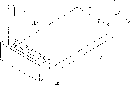
As shown in Figure 1, this wireless pc communication card 1 comprises: the cartridge 2 that cardinal principle is L shaped, and it has comprised a circuit board (not shown) that has a communications portion; And, a connector (not shown) that is provided with and has a plurality of signal pin that are electrically connected with circuit board at the end face 2AX place of a smooth rectangle insertion portion 2A of cartridge 2.
An antenna casing 2B thicker than the insertion portion 2A of cartridge 2 has an antenna casing groove 2BX, wherein be arranged in such a way an antenna part 3 that has a given antenna element (not shown) that is electrically connected with circuit board, be that it can make free pivoted and be accommodated among the antenna casing groove 2BX around an end 3A along the direction that is withdrawn among the antenna casing 2B, and can be along rotating in the opposite direction to rise from outside the antenna casing 2B from antenna casing groove 2BX with this side.
Therefore; this wireless pc communication card 1 can rise from antenna part 3 in communication period; guaranteeing required antenna performance, thereby and antenna part 3 is withdrawn into protect among the antenna casing groove 2BX it not to be subjected to the damage that collision causes that is not intended to owing to for example hand.
In fact, be inserted at insertion portion 2A under the situation of the PC draw-in groove of people's computer (not shown) one by one, wireless pc communication card 1 from the data of personal computer through connector input circuit plate, utilize circuit board that it is carried out required transmission and handle, and send it to other wireless pc communication cards 1 through antenna part 3.
The reception data process antenna part 3 input circuit plates that wireless pc communication card 1 is sent other wireless pc communication cards 1 here carry out required reception to it and handle, and through connector it passed out to personal computer.
In this way, wireless pc communication card 1 is used to receive data and send data to other wireless pc communication cards 1 from other wireless pc communication cards 1.
Yet the wireless pc communication card 1 with such configuration makes antenna part 3 be not easy to work, rises from from antenna casing groove 2BX because antenna part 3 is comprised in when not using among the antenna casing groove 2BX and when being used for communicating by letter.
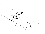
Therefore, such some PC communication card has configuration as shown in Figure 2.
A kind of wireless pc communication card 5 (Fig. 2) with such configuration has the single-piece of being integrated into insertion portion 6A smooth rectangle cartridge 6, that have same thickness and antenna casing 6B, and box 6 comprises a circuit board 7 that has a communications portion.
A connector (not shown) that has a plurality of signal pin that are electrically connected with this circuit board is installed in the end face 6AX place on the insertion portion 6A side of cartridge 6.
An antenna element 8 that comprises crooked conductive foil is formed on the specified portions of circuit board 7 towards antenna casing 6B.Transmission and receiving circuit (not shown) and coupled earthing conductor (not shown) are installed in towards the specified portions of the circuit board 7 of insertion portion 6A.And antenna element 8 is electrically connected with this transmission and receiving circuit.
Therefore, because antenna element 8 is formed on the circuit board 7, wireless pc communication card 5 can be eliminated the operation inconvenience of the above antenna part 3 that is run in conjunction with the described wireless pc communication card 1 of figure L.
In wireless pc communication card 5, the earthing conductor on the circuit board 7 (hereinafter referred to as card side joint earthed conductor) is considered to an antenna element and carries out work with antenna element 8 as dipole antenna.
As shown in Figure 3, when the insertion portion of wireless pc communication card 5 was inserted into the PC draw-in groove 9A of personal computer 9, card side joint earthed conductor and an earthing conductor (did not show; Hereinafter referred to as PC side joint earthed conductor) be electrically connected.Therefore, be positioned at the antenna element 8 outside the personal computer 9 and be positioned at card side within the personal computer 9 and PC side joint earthed conductor (the following combination earthing conductor that is called together) is worked as dipole antenna.
Yet when wireless pc communication card 5 was inserted into personal computer 9, certain metal parts in combination earthing conductor and the personal computer 9 was approaching, thereby had reduced antenna performance and influenced the quality of radio communication.
In addition, in wireless pc communication card 5, the combination earthing conductor is compared with antenna element 8 and is become very big, thereby has reduced to flow through the electric current of antenna element 8 and thereby make the emission of radio wave become difficult.The quality that this has reduced antenna performance and has further influenced radio communication.
Summary of the invention
Consider above-mentioned situation, one object of the present invention provides a kind of radio communication device that can carry out the high-quality radio communication.
Above-mentioned and other purpose of the present invention, accomplished by a kind of radio communication device is provided.A surface and a planar radiation conductor of earthing conductor are arranged in the antenna substantially abreast, a radio communication circuit that carries out radio communication through antenna is contained in the circuit board, antenna and circuit board are inserted into device and keep, and this insertion device is inserted in the electronic installation by stretching out antenna.
Therefore, when the present invention is applied in this electronic installation by being inserted into, the electric current that flows through radiation conductor produces one along the electric field from earthing conductor to radiation conductor between earthing conductor and radiation conductor, so that radiation conductor almost works as an antenna individually, and make earthing conductor hardly as an antenna job.This feasible reduction that can prevent antenna performance.
By being grounding to inserting device, radiation conductor is inserted near the side in the electronic installation earthing conductor, the open end of radiation conductor-it is positioned at apart from the earthing position farthest and sends the strongest radio wave-can be held and leave electronic installation, to reduce the reduction of antenna performance widely.
Description of drawings
From the detailed description of doing below in conjunction with accompanying drawing, it is obvious that character of the present invention, principle and practicality will become.In the accompanying drawings similarly partly with identical label or character representation.
In the accompanying drawings:
Fig. 1 is a schematic isometric, has shown the configuration of traditional wireless pc communication card;
Fig. 2 is a schematic isometric, has shown the configuration of another kind of conventional wireless PC communication card;
Fig. 3 shows the schematic isometric be inserted into the wireless pc communication card in people's computer one by one;
Fig. 4 is the schematic isometric of demonstration according to first embodiment of a kind of generic configuration of a kind of wireless pc communication card of the present invention;
Fig. 5 is the schematic isometric that shows a kind of internal configurations of this wireless pc communication card;
Fig. 6 is the schematic plan view that shows a kind of a kind of configuration of reversed F-typed formation plate antenna;
Fig. 7 is the schematic isometric that shows a kind of layout of this formula of falling F plate aerial;
Fig. 8 is a top schematic view, has shown the operation of this formula of falling F plate aerial;
Fig. 9 shows the schematic isometric be inserted into a kind of wireless pc communication card in people's computer one by one;
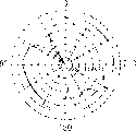
Figure 10 is the schematic diagram that is presented at the field intensity in the formula of the falling F plate aerial;
Figure 11 is the schematic isometric of demonstration according to a kind of configuration of the wireless pc communication card of second embodiment;
Figure 12 is the schematic isometric that shows first and second formula of the falling F plate aerials;
Figure 13 A to 13C is the characteristic curve of the horizontal radiation gain of display radio PC communication card;
Figure 14 is the schematic isometric of demonstration according to a kind of layout of the formula of the falling F plate aerial of another embodiment;
Figure 15 is the schematic isometric of demonstration according to a kind of layout of the formula of the falling F plate aerial of another embodiment;
Figure 16 is the schematic isometric of demonstration according to a kind of layout of the formula of the falling F plate aerial of another embodiment.
Embodiment
Below in conjunction with accompanying drawing most preferred embodiment of the present invention is described.
(1) first embodiment
Referring to Fig. 4, label 10 expressions are according to a kind of wireless pc communication card of first embodiment, it comprises: the single-piece cartridge 11 that cardinal principle is L shaped, this cartridge 11 comprise a smooth rectangle insertion portion 11A and than the thick antenna casing part 11B of insertion portion 11A and comprise a circuit board will describing in the back; And, be installed in the end face 11AX place of insertion portion 11A and have a connector (not shown) of a plurality of signal pin that are electrically connected with circuit board.
Wireless pc communication card 10 is designs like this, be that its insertion portion 11A can be inserted in the PC draw-in groove 17 on the side 14A that is set at the body 14 of people's computer 16 one by one, personal computer 16 comprises body 14, body 14 has operating key 13 and display 15 that links to each other with body, thereby it can freely be opened and closed.Therefore, wireless pc communication card 10 can be inserted in the personal computer 16 and antenna casing 11B is stretched out in removable mode.
In fact, as shown in Figure 5, wireless pc communication card 10 is included in the circuit board 20 in the cartridge 11.
On the inserting side of circuit board 20, be inserted into position in the personal computer 16 facing to insertion portion 11A at circuit board 20, be disposed with digital signal processing circuit constituting a wireless communication section (not shown) and one and send and receiving circuit, extend to antenna casing side facing to antenna casing part 11B from the end face 11AX of insertion portion 11A.
In addition, plane card side joint earthed conductor 21 and the formula of falling F plate aerial 22 are set on the antenna casing side on the surperficial 20A of circuit board 20.
At this, as shown in Figure 6, should the formula of falling F plate aerial 22 comprise one of formation arrowband shape short-circuit conductor 22B and the arrowband shape feed conductor 22C of F on the specified side that is installed in a rectangular radiation conductor plate 22A, they are all made with a metallic plate.
As shown in Figure 7, in this formula of falling F plate aerial 22, short-circuit conductor 22B and feed conductor 22C along with the equidirectional of the about an angle of 90 degrees of radiation conductor plate 22A on crooked, radiation conductor plate 22A and card side joint earthed conductor 21 are provided with substantially abreast with the interval of appointment, and short-circuit conductor 22B is grounded to card side joint earthed conductor 21 near the inserting side of personal computer 16.
On a surperficial 20A of circuit board 20, a fed lines 23 made from conductive pattern is formed on the inserting side and the border between the antenna casing side of personal computer 16, with card side joint earthed conductor 21 electric insulations, and be connected with the receiving circuit (not shown) with transmission.
The feed conductor 22C of the formula of falling F plate aerial 22 is connected with mechanical system with electricity with fed lines 23 near the inserting side of personal computer 16, thereby is electrically connected with transmission and receiving circuit through fed lines 23.
Therefore, when wireless pc communication card 10 is inserted into personal computer 16, its passes through connector handle and sends into digital signal processing circuit from the data of the internal circuit board of personal computer 16, utilize signal processing circuit that it is carried out required signal processing, and it is delivered to other wireless pc communication cards 10 through transmission and receiving circuit with the formula of falling F plate aerial successively.
When the reception data are sent here by a long distance wireless PC communication card 10, local wireless PC communication card 10 receives it by transmission and receiving circuit through the formula of falling F plate aerial 22, it is delivered to digital signal processing circuit so that it is carried out required signal processing, and the signal that is produced is sent to the internal circuit board of personal computer 16 through connector.
In this way, wireless pc communication card 10 is designed to send data and receive data from other wireless pc communication cards to other wireless pc communication cards 10.
In the formula of falling F plate aerial 22, radiation conductor plate 22A and card side joint earthed conductor 21 are provided with abreast substantially and are electrically connected through short-circuit conductor 22B, as described above in connection with Figure 7.
Therefore, in the formula of falling F plate aerial 22, when electric power in operation from for example send and receiving circuit be provided for through feed conductor 22C radiation conductor plate 22A and current i from the short-circuit conductor 22B flow direction when its point farthest promptly flows to the open end 22X of radiation conductor plate 22A, as shown in Figure 8, between radiation conductor plate 22A and a specified portions of card side joint earthed conductor 21, produced an electric field that points to radiation conductor plate 22A from card side joint earthed conductor 21 facing to it.
Therefore, wireless pc communication card 10 is designed to like this, promptly by according to the formula of falling F plate aerial 22 and the intensity of blocking the electric field of generation between the side joint earthed conductor 21 and direction and from the radiation conductor plate 22A emitting radio wave of the formula of falling F plate aerial 22, and the formula of falling F of making plate aerial 22 almost carries out work as an antenna individually, and makes earthing conductor 21 carry out work as antenna hardly.
Therefore, when wireless pc communication card 10 is inserted personal computer 16 as illustrated in fig. 9 and will block side joint earthed conductor 21 and be connected to PC side joint earthed conductor (not shown) in the personal computer 16, comprise that the combination earthing conductor of card side joint earthed conductor 21 and PC side joint earthed conductor is almost gone up not as antenna work.Therefore, though when given metal parts in the personal computer 16 and combination earthing conductor near the time, can prevent that also the antenna performance that sends with reception period from reducing.
In addition, because wireless pc communication card 10 operates the combination earthing conductor this moment hardly as antenna, it can prevent to flow through the decline of the electric current of the formula of falling F plate aerial 22, and this decline can make the emission of radio wave become difficult.Therefore, the reduction of antenna performance has obtained further reducing reliably.
In this formula of falling F plate aerial 22 (Fig. 8), represent that with λ the electrical length of two sides adjacent of rectangular radiation conductor plate 22A is λ/4 if will be used for the wavelength of the frequency of the transmission of data and reception according to the size of radiation conductor plate 22A.
Therefore, shown in the field strength characteristics curve D of Figure 10, electric field of actual generation between the formula of falling F plate aerial 22 and card side joint earthed conductor 21, thereby field intensity is increased to open end 22AX gradually from short dot, and reach minimum (for example to zero) and obtain its maximum at the 22AX place, open end of radiation conductor plate 22A at the short dot that short-circuit conductor 22B is grounding to card side joint earthed conductor 21.
Therefore, the formula of falling F plate aerial 22 increases the radio wave of emission according to field intensity gradually from this short dot to open end 22AX, and is the strongest and in short dot emitting radio wave hardly from the radio wave of open end 22AX emission.
Because the short-circuit conductor 22B of the formula of falling F plate aerial 22 is as in conjunction be grounding to card side joint earthed conductor 21 near the inserting side shown in Figure 7ly, so when wireless pc communication card 10 is inserted into personal computer 16 (Fig. 9), the short-circuit conductor 22B of emitting radio wave is positioned at apart from the open end 22AX of the strongest radiation conductor plate 22A of personal computer 16 nearsides and emitting radio wave and is positioned at away from personal computer 16 places hardly.
This makes that wireless pc communication card 10 can be according to the layout of the formula of falling F plate aerial 22, constitutes shielding to the formula of falling F plate aerial 22 and limit metal parts in the personal computer 16 effectively.Therefore, even when wireless pc communication card 10 is inserted into personal computer 16, the reduction of antenna performance in also can reducing widely to send and receive.
In addition, in wireless pc communication card 10, the formula of falling F plate aerial 22 is fixed on the circuit board 20 in the cartridge 11, with the inconvenience in the operation of eliminating the antenna part 3 that the wireless pc communication card 1 described in conjunction with Fig. 1 run into.
In addition, in wireless pc communication card 10, the feed conductor 22C of the formula of falling F plate aerial 22 near the inserting side of personal computer 16 with circuit board 20 on fed lines 23 be electrically connected and mechanical connection, as in the situation of short-circuit conductor 2B, and transmission and receiving circuit are installed near the circuit board 20 of antenna casing side.This makes and can shorten the fed lines 23 that connects feed conductor 22C and transmission and receiving circuit, thereby the data that reduce greatly on the fed lines 23 send loss.
Under the situation of the above conventional wireless PC communication card of describing in conjunction with Fig. 11, stretch out/retracting device and antenna casing groove 2BX because the antenna casing 2B of cartridge 2 comprises the end and the antenna part 3 of circuit board, antenna casing 2B increases along the longitudinal direction of cartridge 2 and the size of thickness direction.
In addition, under the situation of the above conventional wireless PC communication card of describing in conjunction with Fig. 25 because antenna element 8 is formed on the circuit board 7 and its vertically almost with the parallel longitudinal of cartridge 6, antenna casing 6B increases along the size of the longitudinal direction of cartridge 6.
Therefore, when these traditional wireless pc communication cards 1 and 5 were inserted into personal computer, antenna casing 2B and 6B stretched out from personal computer, thereby had influenced the operability and the portability of personal computer unfriendly.
On the other hand, under situation according to the wireless pc communication card 10 (Fig. 5) of the first embodiment of the present invention, because the electrical length of two sides adjacent of radiation conductor plate 22A is λ/4, can adopt its size of the formula of falling F plate aerial 22-to reduce, and placement make that the longer size of radiation conductor plate 22A is parallel with the width of cartridge 11 like this by the width that reduces radiation conductor plate 22A.As a result, the size of the short direction of antenna casing 11B is little a lot of under can the situation than conventional wireless PC communication card 1 and 5.
In addition, under the situation of wireless pc communication card 10, since the formula of falling F plate aerial 22 with block between the side joint earthed conductor 21 gap (it is selected according to desirable bandwidth) than the antenna part 3 of conventional wireless PC communication card 1 stretch out/the required height of retracting device and antenna casing groove 2BX is little a lot, antenna casing 11B along the thickness direction of cartridge 11 size also can be reduced.
Therefore, when wireless pc communication card 10 was inserted into personal computer 16, the antenna casing 11B that stretches out from personal computer did not influence the operability and the portability of personal computer.
In the above-mentioned configuration of wireless pc communication card 10, card side joint earthed conductor 21 is installed on the antenna casing side of the circuit board 20 that is contained in the cartridge 11, and the formula of falling F plate aerial 22 is arranged in such a way-promptly makes radiation conductor plate 22A and card side joint earthed conductor 21 is essentially parallel to each other.
Therefore, when wireless pc communication card 10 is inserted into personal computer 16 and be in the work, the electric current that flows through the radiation conductor plate 22A of the formula of falling F plate aerial 22 produces one along the electric field from the direction of card side joint earthed conductor 21 to radiation conductor plate 22A, with emitting radio wave between card side joint earthed conductor 21 and radiation conductor plate 22A.
Therefore, wireless pc communication card 10 can make the formula of falling F plate aerial 22 almost work as an antenna, and do not make card side joint earthed conductor 21 (with the PC side joint earthed conductor that is electrically connected with it) carry out work as antenna, thereby even and be electrically connected with PC side joint earthed conductor near the card side joint earthed conductor 21 in the personal computer 16 or card side joint earthed conductor 21 at metal parts thus and make conduction region under the situation of the conduction region of the formula of falling F plate aerial 22, also can prevent the decline of the antenna performance of the formula of falling F plate aerial 22.
In addition, in wireless pc communication card 10, because the short-circuit conductor 22B of the formula of falling F plate aerial 22 is grounded to the card side joint earthed conductor 21 near the circuit board 20 in the inserting side of personal computer 16, the open end 22AX of radiation conductor plate 22A (it is positioned at apart from short-circuit conductor 22B farthest and launches the strongest radio wave) can be held and leave the inserting side.This makes the decline can reduce the antenna performance that causes owing to the shielding action at work of the metal parts in the personal computer 16 greatly.
According to above-mentioned configuration, card side joint earthed conductor 21 is installed near the antenna casing side of the circuit board 20 the inserting side of personal computer 16, and the formula of falling F plate aerial 22 is provided with-is made promptly that like this radiation conductor plate 22A will be parallel to each other substantially with blocking side joint earthed conductor 21.This makes and can make the formula of falling F plate aerial 22 almost carry out work as an antenna individually, and card side joint earthed conductor 21 is worked as antenna, and thereby can prevent to be inserted into the antenna performance reduction that the formula of the falling F plate aerial 20 in the personal computer 16 causes owing to adopting.Therefore, the present invention can realize a kind of wireless pc communication card that the high-quality radio communication is provided.
In addition, because the short-circuit conductor 22B of the formula of falling F plate aerial 22 is grounding to the card side joint earthed conductor 21 near the circuit board the inserting side of personal computer 16 20, the open end 22AX of radiation conductor plate 22A (it apart from short-circuit conductor 22B farthest and the radio wave of launching the strongest) can be away from the inserting side of personal computer 16.This makes and can reduce greatly because the decline of the antenna performance that the metal parts in the personal computer 16 causes, thereby reduces the decline of radio communication quality greatly.
(2) second embodiment
Figure 11 has shown the wireless pc communication card 30 according to second embodiment, wherein with Fig. 5 in corresponding part represent with identical label.Cartridge 11 comprises a circuit board 31, and a connector (not shown) is installed in the end face 11AX place of insertion portion 11A and has a plurality of signal pin that are electrically connected with circuit board.
On circuit board 31, constituting digital signal processing circuit of a wireless communication section (not shown) and transmission and receiving circuit is installed on the inserting side of personal computer (not shown) successively, extend to the antenna casing side from the end face 11AX of insertion portion 11A, wherein transmission and receiving circuit can carry out required the synthesizing of spatial spreading reception.
On a surperficial 31A of circuit board 31, the card side joint earthed conductor 32 of a planar shaped is installed on the antenna casing side.In addition, first and second formula of the falling F plate aerials 33 and 34 intervals with appointment are installed on the Width of cartridge 11.
As shown in figure 12, the configuration mode of first formula of the falling F plate aerial 33 similar with according to the formula of the falling F plate aerial 22 (Fig. 5) of first embodiment: radiation conductor plate 33A and card side joint earthed conductor 32 are with the interval setting abreast substantially of appointment, short-circuit conductor 33B is grounding to the card side joint earthed conductor 32 on the inserting side of personal computer, and first fed lines 35 that feed conductor 33C is electrically connected to and blocks side joint earthed conductor 32 electric insulations.
Second formula of the falling F plate aerial 34 is provided with symmetrically along the Width and first formula of the falling F plate aerial 33 of cartridge 11: a radiation conductor plate 34A is provided with substantially abreast with the interval of card side joint earthed conductor 32 with appointment, short-circuit conductor 34B is grounding to the card side joint earthed conductor 32 on the inserting side of personal computer, and feed conductor 34C is electrically connected with second fed lines 36 with card side joint earthed conductor 32 electric insulations.
On the inserting side of the personal computer of circuit board 31, first and second fed lines 35 and 36 are electrically connected near the antenna casing side and send and receiving circuit.
Therefore, in wireless pc communication card 30, when receiving data and sent by other wireless pc communication cards, receive data through first and second formula of the falling F plate aerials 33 and 34 both and be sent out with receiving circuit and receive.
And, send and receiving circuit in, to carry out from first and second formula of the falling F plate aerials 33 and the 34 reception data that obtain according to all if any the selection synthetic method, etc. the synthetic processing of assignment procedure of the synthetic method that gains etc.
And by the generated data that is produced is delivered to digital signal processing circuit, in this digital signal processing circuit, after the desired signal processing of having carried out generated data, generated data is sent the internal circuit board of personal computer through connector.
In this way, wireless pc communication card 30 is suitably designed, to receive the data that send from other wireless pc communication cards by spatial spreading.
At this, wireless pc communication card 30 makes first and second formula of the falling F plate aerials 33 and 34 boths carry out work as antenna, yet, thereby make it possible to adopt spatial spreading to receive at a distance of enough distances by first and second formula of the falling F plate aerials 33 and 34 being arranged on each other, wireless pc communication card 30 makes them, and each can both carry out work as antenna at reception period, and does not make card side joint earthed conductor 32 carry out work as antenna.This has prevented the decline of antenna performance.
Because wireless pc communication card 30 has near the formula of the falling F plate aerial 33 of the card side joint earthed conductor 32 that is grounded to the inserting side of personal computer and 34 short-circuit conductor 33B and 34B, radiation conductor plate 33A that emitting radio wave is the strongest and the open end of 34A are maintained at leaves personal computer.This makes it possible to reduce greatly the decline of antenna performance.
In addition, use wireless pc communication card 30, shown in Figure 13 A to 13C, if length along cartridge 11, the inserting side that the antenna casing side is used as front (0 among Figure 13 B and Figure 13 C spends the position) and personal computer is used as the back side (180 among Figure 13 B and the 13C spends the position), for example, first formula of the falling F plate aerial 33 (Figure 13 A) has shown the radiation characteristic (Figure 13 B) that right back angle and the left-front corner at horizonally-polarized wave has high radiation gain, and second formula of the falling F plate aerial 34 (Figure 13 A) has shown the radiation characteristic (Figure 13 C) that high radiation gain is arranged at the left rear corner and the right front angle of horizonally-polarized wave.
Therefore, adopt wireless pc communication card 30, the radiation characteristic of the radiation characteristic of common first formula of the falling F plate aerial 33 and second formula of the falling F plate aerial 34 intersects each other on the antenna casing side in front and is complementary.Therefore, when being inserted into personal computer, wireless pc communication card 30 is designed to show that the sensitivity of such radiation characteristic-wherein spatial spreading reception can increase on the antenna casing side in front, promptly increase outside personal computer.
In the configuration of above-mentioned wireless pc communication card 30, card side joint earthed conductor 32 is installed on the antenna casing side of the circuit board 31 that is included in the cartridge 11, first and second formula of the falling F plate aerials 33 and 34 radiation conductor plate 33A and 34A almost are provided with abreast with card side joint earthed conductor 32 respectively, and first and second formula of the falling F plate aerials 33 and 34 so that between radiation conductor plate 33A and the 34A mode of maintenance distance to a declared goal be provided with.
Therefore, adopt first and second formula of the falling F plate aerials 33 and 34, make the wireless pc communication card 30 that inserts personal computer work as an antenna at every turn, and make card side joint earthed conductor 32 (with the PC side joint earthed conductor that is electrically connected with it) hardly as antenna work.Thereby even the card side joint earthed conductor 32 in metal parts and personal computer near or card side joint earthed conductor 32 be electrically connected with PC side joint earthed conductor and make conduction region under the situation of the conduction region of first and second formula of the falling F plate aerials 33 and 34, this also can be by preventing the formula of falling F plate aerial 33 and 34 the decline of antenna performance, receive and obtain good spatial spreading.
In addition, because wireless pc communication card 30 has first and second formula of the falling F plate aerials 33 of card side joint earthed conductor 32 near the inserting side that is grounded to personal computer the circuit board 31 and 34 short-circuit conductor 33B and 34B, it can keep the open end of radiation conductor plate 33A and 34A to leave personal computer, thereby can reduce the decline of the antenna performance of first and second formula of the falling F plate aerials 33 and 34 greatly.Therefore, even when wireless pc communication card 30 is inserted into personal computer, it also can reduce the decline of spatial spreading receiving sensitivity greatly, thereby reduces the decline of radio communication quality.
According to above-mentioned configuration, card side joint earthed conductor 32 is installed on the antenna casing side of the circuit board 31 adjacent with the inserting side of personal computer, and first and second formula of the falling F plate aerials 33 and 34 is provided with-are made promptly like this that their radiation conductor plate 33A is parallel with card side joint earthed conductor 32 cardinal principles with 34A and are maintained at each other the state of a distance apart.Except the effect that above-mentioned first embodiment produces, this configuration also makes the wireless pc communication card 30 that is inserted into personal computer that first and second formula of the falling F plate aerials 33 and 34 are worked as antenna and does not make card side joint earthed conductor 32 as antenna work.This can be by preventing first and second formula of the falling F plate aerials 33 and 34 the decline of antenna performance obtain good spatial spreading and receive.Therefore, even the present invention can realize also providing at the spatial spreading reception period wireless pc communication card of high-quality radio communication.
(3) other embodiment
As seen from Fig. 7 and 12, in above-mentioned first and second embodiment, the formula of the falling F plate aerial 22 or first and second formula of the falling F plate aerials 33 and 34 short-circuit conductor 33B and 34B or feed conductor 33C or the 34C by making short-circuit conductor 22B or feed conductor 22C bends towards radiation conductor plate 22A or radiation conductor plate 33A and 34A, and is set on circuit board 20 or 31.Yet, the invention is not restricted to these configurations.Also can be shown in Figure 14 (wherein representing with identical label) with the corresponding part of Fig. 7 the formula of falling a F plate aerial 22 is arranged on the circuit board 20 by being arranged on cube of separator 40 made from insulation or dielectric material between card side joint earthed conductor 21 and the radiation conductor plate 22A, or shown in Figure 15 (wherein partly representing accordingly), on the inner surface of the top board of the antenna casing 11B by radiation conductor plate 22A being pasted cartridge 11 formula of falling F plate aerial 22 is set with identical label with Fig. 7.
Even this makes the wireless pc communication card be not intended to drop or be subjected to also can keeping the setting and the position of the formula of falling F plate aerial 22, thereby preventing the change of antenna performance under the situation of outside concussion.
As above described in conjunction with Figure 14, when between radiation conductor plate 22A that separator 40 is placed the formula of falling F plate aerial 22 and the card side joint earthed conductor 21, if separator 40 usefulness dielectric materials are made, correspondingly be slower than propagation velocity in free space from the radio wave of the radiation conductor plate 22A emission propagation velocity and the dielectric constant of dielectric material separator 40.This has shortened wavelength, thereby has caused so-called wavelength to reduce effect, the feasible size that can dwindle the radiation conductor plate 22A of the formula of falling F plate aerial 22.Therefore, the wireless pc communication card beguine that can become is little according to the wireless pc communication card 10 and 30 of above-mentioned first and second embodiment.
In addition, though thereby the formula of falling F plate aerial 22 or first and second formula of the falling F plate aerials 33 and 34 width parallel (as from Fig. 5 and 11 as seen)-and described first and second embodiment substantially that is set at the length that makes radiation conductor plate 22A or radiation conductor plate 33A and 34A on circuit board 20 or 31 and cartridge 11 wherein of the such situation of above combination-promptly the invention is not restricted to this.Thereby it is parallel substantially with the length of cartridge 11 also can be arranged on the diagonal of the radiation conductor plate 22A that makes the open end 22AX that engages radiation conductor plate 22A and short dot on the circuit board 20 to the formula of falling F plate aerial 22, (wherein partly represents with identical label accordingly with Fig. 7) as shown in figure 16.
This feasible can being arranged on the open end 22AX of radiation conductor plate 22A apart from personal computer position farthest, and short-circuit conductor 22B is placed apart from nearest position, the inserting side of personal computer.Therefore, when this wireless pc communication card was inserted into personal computer, reducing of the decline of antenna performance was bigger than the wireless pc communication card 10 and 30 of above-mentioned first and second embodiment.
In addition, though situation that above combination is such and having described has adopted the formula of the falling F plate aerial 22 that is made of radiation conductor plate 22A or radiation conductor plate 33A and 34A or first and second formula of the falling F plate aerials 33 and 34 and short-circuit conductor 22B or short-circuit conductor 33B and 34B among first and second embodiment of first and second embodiment-promptly, and short-circuit conductor 22B and short-circuit conductor 33B and 34B and feed conductor 22C or feed conductor 33C and 34C make with a conductive metal sheet, the invention is not restricted to this.Also can by form with a polyamide or other resin moldings radiation conductor plate, short-circuit conductor and feed conductor and with plating, deposit or any other method on this film coated with conductive metal layer, and the formation formula of falling F plate aerial.And this formula of falling F plate aerial will provide the advantage identical with first and second embodiment.
Further, though in conjunction with such situation described second embodiment-promptly wherein first and second formula of the falling F plate aerials 33 and 34 be set on the circuit board 31 and receive to carry out spatial spreading, the invention is not restricted to this.Can be provided with on circuit board also that the two or more formula of falling F plate aerials-they have thereby the radiation conductor plate parallel substantially with one or more card side joint earthed conductor-can the carry out spatial spreading in the identical or different frequency band receives, polarization is discrete receives and the discrete reception of other types.
In addition, though above combination such situation described the present invention of first and second embodiment-wherein be applied to meeting the PCMCIA standard wireless pc communication card 10 and 30 with as above in conjunction with constructing a kind of WLAN as described in Fig. 5 and 11, the invention is not restricted to this.It can be widely used in such as the different shape of the different shape of card shape or rod and various types of radio communication devices, they comprise the radio communication device that can carry out data communication through personal handy phone system (PHS), as long as can be inserted in the various electronic installations such as personal computer.
In addition, wherein they have adopted card side joint earthed conductor 21 or 32 and the formula of falling F plate aerial 22 or first and second formula of the falling F plate aerials 33 and 34 and the surface and the setting abreast of radiation conductor plate cardinal principle of earthing conductor in these antenna though described first and second embodiment-promptly in conjunction with such situation, the invention is not restricted to this.It can adopt multiple antenna, comprises a kind of unidirectional short circuit antenna, and wherein earthing conductor surface and a planar radiation conductor are provided with substantially abreast.
Further, though the such situation of above combination described first and second embodiment-promptly wherein rectangular radiation conductor plate 22A or rectangular radiation conductor plate 33A and 34A be used as the radiation conductor of planar shaped, the invention is not restricted to this.Can adopt the radiation conductor of various widely profiles and pattern on the other hand, comprise the connector of crooked shape, as long as they are planes.
In addition, though the such situation of above combination has been described first and second embodiment-promptly wherein the be included in circuit board from insertion portion 11A to antenna casing 1B 20 or 31 in the cartridge 11 and has been used as and comprises the circuit board that carries out the radio communication circuit of radio communication by this antenna, the invention is not restricted to this.It can adopt the circuit board of various widely profiles and shape, as long as they have the radio communication line of the radio communication that is used to pass through antenna.
In addition, though the such situation of above combination described first and second embodiment-promptly wherein substantially L shaped cartridge 11 be used as holding circuit plate and antenna and when antenna stretches out, be inserted into the insertion device of the electronic installation of appointment, the invention is not restricted to this.It can adopt the insertion device of various other shapes and structure, as long as they keep this circuit and antenna and they can be inserted into the electronic installation of appointment under the state that antenna stretches out.
Further, first and second embodiment-promptly wherein personal computer 16 is used as the insertion electronic installation that device was inserted into, and the invention is not restricted to this though the such situation of above combination has been described.It can adopt various electronic installations, comprises desktop personal computers and PDA(Personal Digital Assistant).
As mentioned above, according to the present invention, a kind of insert device kept surface of the earthing conductor of a kind of antenna-wherein and planar shaped radiation conductor be provided with abreast substantially-and comprise a circuit board that carries out the radio communication circuit of radio communication through antenna.Because inserting device is inserted in the electronic installation under the state that antenna stretches out, the electric current that flows through radiation conductor produces one along the electric field from earthing conductor to the radiation conductor direction between earthing conductor and radiation conductor, thereby radiation conductor is almost worked as an antenna individually, and earthing conductor is worked as antenna.This makes it possible to prevent that thereby the decline of antenna performance from providing high-quality radio communication.
In addition, by making radiation conductor near inserting device insertion electronic installation place, be grounded to earthing conductor, the radio wave that the open end of radiation conductor-it is positioned at apart from the earthing position farthest and emission is the strongest-can be maintained at the state that leaves electronic installation, thus the decline of antenna performance and the decline of radio communication quality reduced widely.
Though more than described most preferred embodiment of the present invention, those skilled in the art is apparent that can carry out various changes and correction and appending claims has covered all these changes and correction within the spirit and scope of the invention.
Claims (3)
1. radio communication device comprises:
The formula of falling a F plate aerial, wherein earthing conductor surface and a planar radiation conductor are provided with substantially abreast;
A circuit board, it comprises a radio communication circuit that carries out radio communication through described antenna; And
Insert device, it keeps described circuit board and described antenna, and in antenna is placed on antenna casing and be inserted into the electronic installation of an appointment under the state that antenna casing stretches out.
2. according to the radio communication device of claim 1, the described radiation conductor of wherein said antenna is grounding to described earthing conductor be inserted into a side of described electronic installation at described insertion device near.
3. according to the radio communication device of claim 1, a surface of one or more described earthing conductors of wherein said antenna and a plurality of described radiation conductor are provided with substantially abreast.
Applications Claiming Priority (2)
| Application Number | Priority Date | Filing Date | Title |
|---|---|---|---|
| JP048967/2000 | 2000-02-21 | ||
| JP2000048967A JP2001237625A (en) | 2000-02-21 | 2000-02-21 | Radio communication equipment |
Publications (2)
| Publication Number | Publication Date |
|---|---|
| CN1324125A CN1324125A (en) | 2001-11-28 |
| CN1201430C true CN1201430C (en) | 2005-05-11 |
Family
ID=18570969
Family Applications (1)
| Application Number | Title | Priority Date | Filing Date |
|---|---|---|---|
| CNB011046767A Expired - Fee Related CN1201430C (en) | 2000-02-21 | 2001-02-21 | Radio communication device |
Country Status (6)
| Country | Link |
|---|---|
| US (1) | US20020034966A1 (en) |
| EP (1) | EP1128465A3 (en) |
| JP (1) | JP2001237625A (en) |
| KR (1) | KR20010083181A (en) |
| CN (1) | CN1201430C (en) |
| TW (1) | TW501310B (en) |
Families Citing this family (25)
| Publication number | Priority date | Publication date | Assignee | Title |
|---|---|---|---|---|
| US6928301B2 (en) * | 2000-08-11 | 2005-08-09 | Novatel Wireless, Inc. | Distributed architecture wireless RF modem |
| JP3810265B2 (en) * | 2000-09-19 | 2006-08-16 | インターナショナル・ビジネス・マシーンズ・コーポレーション | Computer system |
| WO2003041222A1 (en) * | 2001-11-09 | 2003-05-15 | Nippon Tungsten Co., Ltd. | Antenna |
| JP3665620B2 (en) * | 2002-03-28 | 2005-06-29 | 株式会社東芝 | Wireless data communication card and antenna applied thereto |
| AU2003266670A1 (en) * | 2002-10-03 | 2004-04-23 | Matsushita Electric Industrial Co., Ltd. | Terminal apparatus |
| JP3742384B2 (en) * | 2002-12-25 | 2006-02-01 | 株式会社東芝 | Electronics |
| TW578942U (en) * | 2002-12-31 | 2004-03-01 | Asustek Comp Inc | Printed circuit board antenna assembled inside panel of computer housing |
| JP4128102B2 (en) * | 2003-04-14 | 2008-07-30 | シャープ株式会社 | Wireless transmit / receive card |
| JP3886932B2 (en) * | 2003-06-04 | 2007-02-28 | 太陽誘電株式会社 | Antenna mounting substrate and PC card provided with the same |
| JP4070689B2 (en) * | 2003-08-20 | 2008-04-02 | シャープ株式会社 | Wireless communication unit |
| US7324835B2 (en) * | 2004-08-07 | 2008-01-29 | C-One Technology Corporation | Motherboard and daughterboard multi-swap system with communication module for a GPRS system |
| US7324051B2 (en) * | 2004-10-12 | 2008-01-29 | Sony Ericsson Mobile Communications Ab | Supplemental parasitic antenna apparatus |
| US20060168090A1 (en) * | 2005-01-07 | 2006-07-27 | United Technologies Corporation | Remote integrated subsystems in an aircraft or the like |
| CN101138161B (en) * | 2005-03-17 | 2011-03-16 | 株式会社村田制作所 | Card-type device and method of producing the same |
| JP4500214B2 (en) * | 2005-05-30 | 2010-07-14 | 株式会社日立製作所 | Wireless IC tag and method of manufacturing wireless IC tag |
| US7382625B2 (en) | 2006-01-23 | 2008-06-03 | Sony Ericsson Mobile Communications Ab | Combination antenna and SIM card support structure |
| TW200843229A (en) * | 2007-01-03 | 2008-11-01 | Newton Peripherals Llc | Dongle device |
| US20080231520A1 (en) * | 2007-03-22 | 2008-09-25 | Zueck Joseph | Modem card with three-dimensional antenna arrangement |
| TWI380501B (en) * | 2007-08-22 | 2012-12-21 | Wistron Corp | Antenna structure and related expansion card and computer apparatus |
| US7952528B2 (en) * | 2007-09-04 | 2011-05-31 | Sierra Wireless, Inc. | Antenna configurations for compact device wireless communication |
| JP5367245B2 (en) * | 2007-09-28 | 2013-12-11 | 京セラ株式会社 | Wireless communication device |
| JP5901130B2 (en) * | 2011-03-29 | 2016-04-06 | 富士通コンポーネント株式会社 | Antenna device, circuit board, and memory card |
| CN215881531U (en) | 2017-08-07 | 2022-02-22 | 米沃奇电动工具公司 | Electric tool and electric tool device |
| US11665519B2 (en) | 2019-02-06 | 2023-05-30 | Milwaukee Electric Tool Corporation | Power tool with shared terminal block |
| WO2021102289A1 (en) * | 2019-11-21 | 2021-05-27 | Milwaukee Electric Tool Corporation | Insertable wireless communication device for a power tool |
Family Cites Families (2)
| Publication number | Priority date | Publication date | Assignee | Title |
|---|---|---|---|---|
| US5606732A (en) * | 1994-04-26 | 1997-02-25 | Rockwell International Corporation | Direct connect radio and antenna assembly |
| JPH1063808A (en) * | 1996-08-27 | 1998-03-06 | Yamaha Corp | Pc card |
-
2000
- 2000-02-21 JP JP2000048967A patent/JP2001237625A/en active Pending
-
2001
- 2001-02-15 US US09/783,806 patent/US20020034966A1/en not_active Abandoned
- 2001-02-15 TW TW090103461A patent/TW501310B/en not_active IP Right Cessation
- 2001-02-19 KR KR1020010008256A patent/KR20010083181A/en not_active Application Discontinuation
- 2001-02-19 EP EP01301439A patent/EP1128465A3/en not_active Withdrawn
- 2001-02-21 CN CNB011046767A patent/CN1201430C/en not_active Expired - Fee Related
Also Published As
| Publication number | Publication date |
|---|---|
| CN1324125A (en) | 2001-11-28 |
| KR20010083181A (en) | 2001-08-31 |
| US20020034966A1 (en) | 2002-03-21 |
| TW501310B (en) | 2002-09-01 |
| JP2001237625A (en) | 2001-08-31 |
| EP1128465A2 (en) | 2001-08-29 |
| EP1128465A3 (en) | 2003-05-07 |
Similar Documents
| Publication | Publication Date | Title |
|---|---|---|
| CN1201430C (en) | Radio communication device | |
| CN1073748C (en) | Bidirectional printed antenna | |
| CN1303723C (en) | Stacked pattern antenna and radio communication device using the same | |
| CN1293671C (en) | Gap butterfly antenna with passive device | |
| CN1195355C (en) | Radio communication device, and electronic device using same | |
| CN1235315C (en) | Antenna and electron device containing said antenna | |
| CN1133237C (en) | Co-axial-resonating slot antenna, production method thereof and wireless terminal | |
| CN1147022C (en) | Antenna device and portable radio communication apparatus | |
| CN1127171C (en) | Short-circuit microstrip antenna and device including that antenna | |
| CN1159803C (en) | Surface mounted antenna and communication apparatus equipped therewith | |
| CN1166034C (en) | Space-saving built-in groove type antenna | |
| CN1510885A (en) | Portable wireless communication apparatus | |
| CN1574456A (en) | Multi-frequency antenna | |
| US10978795B2 (en) | Antenna structure and wireless communication device using the same | |
| CN1509505A (en) | Antenna device for radio apparatus | |
| CN1465118A (en) | Built in antenna apparatus | |
| CN1655398A (en) | Loop antenna and radio communication device having the same | |
| CN1519981A (en) | ELectronic appts. and printed circuit board for mounting antenna | |
| CN1466800A (en) | Portable radio apparatus antenna | |
| CN1933607A (en) | Mobile transceiver and antenna device | |
| CN1285626A (en) | Asymmetric dipole antenna assembly | |
| CN1241293C (en) | built-in antenna of portable radio apparatus | |
| CN1913224A (en) | Circuit board antenna | |
| CN1490897A (en) | Antenna structure and communication equipment including it | |
| CN101075699A (en) | Foldable wideband antenna and using method of the same |
Legal Events
| Date | Code | Title | Description |
|---|---|---|---|
| C10 | Entry into substantive examination | ||
| SE01 | Entry into force of request for substantive examination | ||
| C06 | Publication | ||
| PB01 | Publication | ||
| C14 | Grant of patent or utility model | ||
| GR01 | Patent grant | ||
| C19 | Lapse of patent right due to non-payment of the annual fee | ||
| CF01 | Termination of patent right due to non-payment of annual fee |