CN1198678A - Sterilizer testing systems - Google Patents
Sterilizer testing systems Download PDFInfo
- Publication number
- CN1198678A CN1198678A CN96197352.8A CN96197352A CN1198678A CN 1198678 A CN1198678 A CN 1198678A CN 96197352 A CN96197352 A CN 96197352A CN 1198678 A CN1198678 A CN 1198678A
- Authority
- CN
- China
- Prior art keywords
- heat
- pipe
- disinfectant
- vestibule
- temperature sensor
- Prior art date
- Legal status (The legal status is an assumption and is not a legal conclusion. Google has not performed a legal analysis and makes no representation as to the accuracy of the status listed.)
- Pending
Links
- 238000012360 testing method Methods 0.000 title abstract description 65
- 238000004659 sterilization and disinfection Methods 0.000 claims abstract description 109
- 238000009825 accumulation Methods 0.000 claims abstract description 5
- 239000000645 desinfectant Substances 0.000 claims description 72
- 239000000463 material Substances 0.000 claims description 43
- 238000009413 insulation Methods 0.000 claims description 14
- 238000010521 absorption reaction Methods 0.000 claims description 7
- 230000008595 infiltration Effects 0.000 claims description 7
- 238000001764 infiltration Methods 0.000 claims description 7
- 238000007789 sealing Methods 0.000 claims description 5
- 230000001954 sterilising effect Effects 0.000 abstract description 13
- 230000035515 penetration Effects 0.000 abstract description 4
- 239000011810 insulating material Substances 0.000 abstract description 2
- 230000005494 condensation Effects 0.000 abstract 1
- 238000009833 condensation Methods 0.000 abstract 1
- 239000000126 substance Substances 0.000 description 18
- 230000000249 desinfective effect Effects 0.000 description 11
- 238000000034 method Methods 0.000 description 10
- 230000008859 change Effects 0.000 description 8
- 239000005022 packaging material Substances 0.000 description 6
- 230000008569 process Effects 0.000 description 6
- 230000000694 effects Effects 0.000 description 5
- 238000005259 measurement Methods 0.000 description 4
- 238000012856 packing Methods 0.000 description 4
- 241000270728 Alligator Species 0.000 description 3
- 210000004027 cell Anatomy 0.000 description 3
- 230000000875 corresponding effect Effects 0.000 description 3
- 230000007613 environmental effect Effects 0.000 description 3
- 230000005484 gravity Effects 0.000 description 3
- 230000006698 induction Effects 0.000 description 3
- XLYOFNOQVPJJNP-UHFFFAOYSA-N water Substances O XLYOFNOQVPJJNP-UHFFFAOYSA-N 0.000 description 3
- OKTJSMMVPCPJKN-UHFFFAOYSA-N Carbon Chemical compound [C] OKTJSMMVPCPJKN-UHFFFAOYSA-N 0.000 description 2
- 229920000106 Liquid crystal polymer Polymers 0.000 description 2
- 239000004977 Liquid-crystal polymers (LCPs) Substances 0.000 description 2
- 229910052782 aluminium Inorganic materials 0.000 description 2
- XAGFODPZIPBFFR-UHFFFAOYSA-N aluminium Chemical group [Al] XAGFODPZIPBFFR-UHFFFAOYSA-N 0.000 description 2
- 238000013459 approach Methods 0.000 description 2
- 238000003556 assay Methods 0.000 description 2
- 238000009835 boiling Methods 0.000 description 2
- 239000002131 composite material Substances 0.000 description 2
- 238000010276 construction Methods 0.000 description 2
- 230000008602 contraction Effects 0.000 description 2
- 238000005202 decontamination Methods 0.000 description 2
- 230000003588 decontaminative effect Effects 0.000 description 2
- 239000004744 fabric Substances 0.000 description 2
- 239000006261 foam material Substances 0.000 description 2
- 239000003365 glass fiber Substances 0.000 description 2
- 229910052751 metal Inorganic materials 0.000 description 2
- 239000002184 metal Substances 0.000 description 2
- 238000012544 monitoring process Methods 0.000 description 2
- BASFCYQUMIYNBI-UHFFFAOYSA-N platinum Chemical compound [Pt] BASFCYQUMIYNBI-UHFFFAOYSA-N 0.000 description 2
- 229920006395 saturated elastomer Polymers 0.000 description 2
- 229910001220 stainless steel Inorganic materials 0.000 description 2
- 239000010935 stainless steel Substances 0.000 description 2
- 229920002430 Fibre-reinforced plastic Polymers 0.000 description 1
- 235000014676 Phragmites communis Nutrition 0.000 description 1
- 239000004696 Poly ether ether ketone Substances 0.000 description 1
- 229920000491 Polyphenylsulfone Polymers 0.000 description 1
- 229910000831 Steel Inorganic materials 0.000 description 1
- 239000002250 absorbent Substances 0.000 description 1
- 230000002745 absorbent Effects 0.000 description 1
- 230000009471 action Effects 0.000 description 1
- 230000004888 barrier function Effects 0.000 description 1
- 230000005540 biological transmission Effects 0.000 description 1
- 230000015572 biosynthetic process Effects 0.000 description 1
- 229910052799 carbon Inorganic materials 0.000 description 1
- 235000019994 cava Nutrition 0.000 description 1
- 210000002421 cell wall Anatomy 0.000 description 1
- 239000003153 chemical reaction reagent Substances 0.000 description 1
- 229920001577 copolymer Polymers 0.000 description 1
- 230000002596 correlated effect Effects 0.000 description 1
- 230000007423 decrease Effects 0.000 description 1
- 230000003111 delayed effect Effects 0.000 description 1
- 238000001514 detection method Methods 0.000 description 1
- 238000001035 drying Methods 0.000 description 1
- 229920001971 elastomer Polymers 0.000 description 1
- 230000002349 favourable effect Effects 0.000 description 1
- 239000000835 fiber Substances 0.000 description 1
- 239000011151 fibre-reinforced plastic Substances 0.000 description 1
- 239000006260 foam Substances 0.000 description 1
- 229910002804 graphite Inorganic materials 0.000 description 1
- 239000010439 graphite Substances 0.000 description 1
- 238000011534 incubation Methods 0.000 description 1
- 239000012774 insulation material Substances 0.000 description 1
- 238000012986 modification Methods 0.000 description 1
- 230000004048 modification Effects 0.000 description 1
- 239000012466 permeate Substances 0.000 description 1
- 229910052697 platinum Inorganic materials 0.000 description 1
- 229920002492 poly(sulfone) Polymers 0.000 description 1
- 229920002530 polyetherether ketone Polymers 0.000 description 1
- -1 polytetrafluoroethylene Polymers 0.000 description 1
- 229920001343 polytetrafluoroethylene Polymers 0.000 description 1
- 239000004810 polytetrafluoroethylene Substances 0.000 description 1
- 239000011148 porous material Substances 0.000 description 1
- 238000012545 processing Methods 0.000 description 1
- 239000007921 spray Substances 0.000 description 1
- 239000010959 steel Substances 0.000 description 1
- 239000000758 substrate Substances 0.000 description 1
- 238000010998 test method Methods 0.000 description 1
- 239000004753 textile Substances 0.000 description 1
- 238000005406 washing Methods 0.000 description 1
Images


Classifications
-
- A—HUMAN NECESSITIES
- A61—MEDICAL OR VETERINARY SCIENCE; HYGIENE
- A61L—METHODS OR APPARATUS FOR STERILISING MATERIALS OR OBJECTS IN GENERAL; DISINFECTION, STERILISATION OR DEODORISATION OF AIR; CHEMICAL ASPECTS OF BANDAGES, DRESSINGS, ABSORBENT PADS OR SURGICAL ARTICLES; MATERIALS FOR BANDAGES, DRESSINGS, ABSORBENT PADS OR SURGICAL ARTICLES
- A61L2/00—Methods or apparatus for disinfecting or sterilising materials or objects other than foodstuffs or contact lenses; Accessories therefor
- A61L2/24—Apparatus using programmed or automatic operation
-
- A—HUMAN NECESSITIES
- A61—MEDICAL OR VETERINARY SCIENCE; HYGIENE
- A61L—METHODS OR APPARATUS FOR STERILISING MATERIALS OR OBJECTS IN GENERAL; DISINFECTION, STERILISATION OR DEODORISATION OF AIR; CHEMICAL ASPECTS OF BANDAGES, DRESSINGS, ABSORBENT PADS OR SURGICAL ARTICLES; MATERIALS FOR BANDAGES, DRESSINGS, ABSORBENT PADS OR SURGICAL ARTICLES
- A61L2/00—Methods or apparatus for disinfecting or sterilising materials or objects other than foodstuffs or contact lenses; Accessories therefor
- A61L2/26—Accessories or devices or components used for biocidal treatment
- A61L2/28—Devices for testing the effectiveness or completeness of sterilisation, e.g. indicators which change colour
Landscapes
- Health & Medical Sciences (AREA)
- Epidemiology (AREA)
- Life Sciences & Earth Sciences (AREA)
- Animal Behavior & Ethology (AREA)
- General Health & Medical Sciences (AREA)
- Public Health (AREA)
- Veterinary Medicine (AREA)
- Apparatus For Disinfection Or Sterilisation (AREA)
Abstract
A sterilant challenge device (50), for use in testing the efficiency of the air removal stage of a sterilization cycle in a sterilizer, includes a tube (2) of thermally-insulating material, the bore of which is closed at one end (52) and open at the other for the entry of sterilant. A plurality of thermally-conductive masses (51) are located around the tube (2) and thermally-separated from one another by air gaps (59), and a temperature sensor is located in an opening (61) in one of the masses adjacent the closed end of the tube. An outer casing (25) defines an air space around the thermally-conductive masses and thermally insulates the masses from the heat in the sterilizer. When the challenge device is located in a sterilizer, the penetration of sterilant along the bore of the tube (2) during a sterilization cycle, is inhibited by the accumulation of air and/or non-condensable gas within the bore resulting from the condensation of moisture on the walls of the bore. By measuring the temperature in a thermally-conductive mass (51) adjacent the closed end of the tube (2), the presence of sterilant in the adjacent region of the bore of the tube can be detected.
Description
The present invention relates to determine the System and method for of the effectiveness of disinfection cycle in the disinfector.
A kind of disinfecting process that in the past was used for sterilizing medical treatment and hospital equipment only reaches in the disinfection cavity of disinfector under the combination of particular environment condition just effectively.For example, when steam was used as disinfectant, the purpose of disinfecting process was to provide the steam of suitable quality, and contacted an appropriate period with all surface of wanting sterilizing objects with a suitable temperature.
In some steam disinfecting apparatuss, disinfecting process generally divides three Main Stage to carry out.In the phase I, remove the air that is entrained in the input thing to be processed.Second stage is sterilisation stage, and the effect of wherein importing thing withstanding pressure steam under the combination condition of time of approving and temperature carries out disinfection.Phase III is a drying stage, wherein removes the concretion that pro-formed in two stages by the emptying disinfection cavity.
Can air be removed in disinfection cavity by number of ways.For example, in gravity steam (gravity steam) disinfector, the principle that has adopted gravity to move, wherein the steam that enters on the disinfection cavity top is taken away air by the valve that is positioned at the disinfection cavity bottom.On the other hand, in the steam disinfecting apparatus of evacuation in advance, by the height evacuation of disinfection cavity or by being lower than atmospheric pressure and/or being higher than under the situation of atmospheric pressure, evacuation and steam spray to combine to be taken away air by force.
Any air that leaks into owing to the packing ring, valve or the sealing member that damage in the disinfection cavity in the air empty stage in this cycle stage that do not remove in disinfection cavity or that be lower than atmospheric pressure can form air pocket during wanting disinfectant input thing.Equally, be present in the disinfection cavity or be entrained in any non-condensing gas (being meant that its boiling point is lower than the gas of disinfectant boiling point here) that enters disinfection cavity in the steam and can in the input thing, form the gas cave.This air pocket or gas cave will produce to the infiltration of steam and hinder, thereby make all surfaces of input thing can not reach competent conditions for sterilization.When sterilization such as plain cloth of hospital or the porous material the fabric,, air pocket or gas cave infiltrate to the internal layer of these materials, so this situation especially easily takes place because having hindered steam.Consequent result promptly can not carry out disinfection.Therefore, need to determine the effectiveness of disinfection cycle, especially determine whether enough water vapour penetration.Similarly, when using a kind of disinfectant rather than steam, need to determine whether this disinfectant sufficiently infiltrates the input thing to carry out disinfection.
A kind of commonly used being used to is determined at the effectiveness that the air empty stage air in porous input thing vapor sterilization cycle discharges and/or is used to test the method that non-condensing gas exists and be known Bowie-Dick method of testing.Typical B owie-Dick test suite is made up of the towel of newly washing that is folded into special size basically, is placing a chemical indicator sheet on the center of assembly.The chemical indicator assay sheet has experienced the visible change that fades to another kind of color from a kind of specific color, such as, just fade to final black in case be exposed to disinfecting process by initial white.If do not discharge the air in the disinfector fully, if perhaps exist the non-condensing gas of sufficient amount in disinfecting process, then the air cave will be formed on the center of assembly, thus overslaugh steam contact with steam sensitive chemical indicator sheet.The result that inadequate steam infiltrates is the lip-deep uneven change color of chemical indicator assay sheet: so, by the shown failure record of indicator the existence in air cave, so that experience complete or uniform change color, represent sufficient water vapour penetration.
Also can adopt biological display that the information of sufficient disinfection cycle is provided.Biology display apparatus test system generally adopts the spore alive of experience disinfection cycle.After the cycle, sporocyst has been hatched, and this system detects whether any growth is arranged.If growth does not represent that then this disinfecting process is effective.So biological display can determine whether to exist the disinfectant condition, but because the cause of incubation cycle, the result generally was at least 24 hours the required time for acquisition.Therefore, because the change color of chemical indicator provides the result of moment, so usually biological display system and chemical indicator are combined use.In addition, by using chemical indicator and biological display that the information of sufficient air empty stage and sterilisation stage can be provided.
Also can adopt parameter monitoring to monitor or control disinfection cycle, to guarantee to obtain suitable conditions for sterilization.For example, United States Patent (USP) 4 by the Childress invention, 865, disclosed a kind of automatic sterilizer No. 814, this disinfector comprises a microprocessor, this microprocessor monitors disinfection cavity temperature inside and force value, and control a heater, so that before starting an intervalometer, make temperature and pressure reach predetermined value.In case after intervalometer started, if pressure and temperature value are brought down below predetermined minima, then intervalometer stopped.Because as everybody knows, in the time of in saturated vapor is enclosed in annular seal space, the pressure of saturated vapor and temperature variable are correlated variabless, therefore these two variablees are monitored and can be guaranteed to keep suitable condition during sterilizing.
Though, preferably monitor in the disinfection cavity self environmental condition, it is generally acknowledged that being more preferably monitoring wants that disinfectant is actual to be imported in the thing or represent environmental condition in the test suite (such as the Bowie-Dick test suite) of this input thing.Enough determine the effectiveness of the air empty stage of the disinfector of evacuation in advance though it has been generally acknowledged that typical B owie-Dick test suite, it still exists many shortcomings.Because test suite is not assembled in advance, monitor the disinfector performance so must constitute it when using this method at every turn.Prepare, assembling and to use the towel assembly be elapsed time and energy, in addition, such as wash, the variable factor moistening, towel thickness and wearing and tearing and the employed towel bar number all can change test result in advance.Therefore, improved alternative Bowie-Dick test suite, so that overcome these restrictions.
The another kind of Bowie-Dick test suite that is used for steam or gas sterilizer has been described in EP-A-0419282.This test suite comprises that one has the container of roof and diapire, is placing the porous packaging material in this container.This packaging material are restricted the disinfectant infiltration by a restricted approach is provided, and this approach hinders disinfectant and flows through test suite.The bottom of one removable cap sealed container is positioned at a hole on the vessel top wall simultaneously and steam is flowed into be positioned at packaging material among the container downwards.This test suite comprises that one is used to detect the chemical indicator that disinfectant is infiltrated.If disinfectant is the packaging material of penetration test assembly successfully, then the chemical indicator sheet will experience once change color completely.If disinfectant is not sufficiently infiltrated packaging material, then this chemical indicator will can not experience once thoroughly uniform change color, thereby the emptying of expression air is inadequate, perhaps also exists non-condensing gas, perhaps in other words, Bowie-Dick test crash.
At EP-A-0 421 760; US-A-5 066 464; The test suite of other use in steam or gas sterilizer described among WO 93/21964 and the US-A-5 270 217.In each test suite, the disinfectant that comes from disinfection cavity must be passed physics (physical) obstacle of certain form before its arrival is arranged in the disinfectant pick off of test suite.For example, at WO 93/21964 a kind of test cell has been described, this test cell comprises a test chamber, this test chamber has the opening that an ambient atmos enters on the one end, on its other end, has a temperature sensor, between temperature sensor and opening, has a heat abstractor (for example, husky net, felt, porous (open-celled) polymeric foam material).
US-A-4 594 223 has described the various devices that have non-condensing gas in the disinfection cavity that are used to be illustrated in.In the kind of means, heat and humidity sensor are positioned at the least significant end of elongate chamber therein, and the upper end in this chamber is opened wide.The intracavity of the heat sink material of fibrous insulating material state between opening and pick off.In another kind of means, the passage between opening and pick off is by a radiator, and this radiator is an aluminum that is surrounded by heat-barrier material, rather than by the fiber heat sink material.
US-A-4 115 068 has described the air display device of a kind of use in disinfector, and this device comprises an axial pipe, the bottom end opening of this pipe, and its top closure.This pipe is to be made at the heat-barrier material that it has on the inner surface of Heat Conduction Material by lining.One thermal discharge extends axially to pipe.
Another kind of knownly make disinfectant be difficult to infiltrate to the device of the specific position that is arranged in a test suite to comprise a quite long stainless steel tube (being generally 1.5 meters), this stainless steel tube has a narrower vestibule (being generally 2.0 millimeters), and this vestibule provides and made the unique inlet of disinfectant infiltration to the precalculated position.
The present invention provides a kind of disinfectant that is used for sterilizer testing systems to detect (challenge) device in order to address the above problem, and the structure of this device is considerably simple, but it but can identify invalid disinfection cycle reliably.
The invention provides a kind of use is used for determining the air empty stage of disinfection cycle in disinfector the disinfectant checkout gear of effectiveness, this device comprises that one constitutes the chamber of a free space; One is used for the opening that disinfectant enters into free space; One radiator portion, when this device used in a disinfector, the radiator portion preferential absorption came from the heat of free space; And be used to install a pick off to detect the device that exists of disinfectant on the above-mentioned opening of distance precalculated position far away, that be positioned at free space, the wall in chamber contains heat-barrier material, this heat-barrier material has stoped the heat that comes from the disinfector to be passed to free space by the wall in chamber, thereby during disinfection cycle, by by hydrogenesis caused accumulation that is positioned at the air and/or the non-condensing gas of free space on the wall in chamber, the disinfectant that can suppress to come from above-mentioned opening is penetrated into the precalculated position.
This device can be equipped with a pick off that is used to detect the existence of disinfectant on the precalculated position.This pick off can comprise that one is used to detect the temperature sensor of the temperature on the precalculated position.Alternatively or and this pick off can comprise that one is used to measure the humidity sensor of the existence of the moisture on the precalculated position.Alternatively or and this pick off can comprise that one is used to detect the biological/chemical sensor of the existence of disinfectant on the precalculated position.
This radiator portion can by an insulating portion around, thereby in disinfection cycle, radiator portion comes from preferential absorption the heat of free space.
This chamber can comprise a passage, the sealing of an end of this passage, and the precalculated position is near the blind end of this passage, is used for the other end that opening that disinfectant enters is positioned at passage.Passage can be the vestibule of the pipe that is positioned at a heat-barrier material, and radiator portion can comprise that in a large number this heat carrier is heat insulation mutually along the length of the pipe heat carrier around pipe.In addition, this passage can be made by many heat-barrier materials; Under the sort of situation, the inside of this heat-barrier material sheet forms the radiator portion of device, and the effect of insulating portion is then played in its outside, thereby during sterilizing, this radiator portion comes from preferential absorption the heat of free space.
In addition, this passage can comprise the partitioned portion of some intercommunications.Under latter instance, but straight line is settled partitioned portion, is used for the end that opening that disinfectant enters is positioned at the partitioned portion that straight line settles, and the precalculated position then is positioned on the other end of the partitioned portion that straight line settles.In addition, partitioned portion also can be settled like this, at least one partitioned portion by other separating part branch around, be used for the partitioned portion that opening that disinfectant enters is positioned at this structural perimeter, the precalculated position then is positioned on the central compartment part.The radiator portion of device can comprise the radiator that is positioned at partitioned portion.
The present invention also provides the disinfectant checkout gear of the effectiveness of a kind of use is used for determining disinfection cycle in disinfector air empty stage, this device comprises the pipe of a heat-barrier material, the vestibule that constitutes the pipe of a free space can enter in the upper shed of one end for making disinfectant, and the other end then seals; Some length along pipe are around the heat carrier of pipe, and this heat carrier is heat insulation mutually; And around the insulating portion of pipe and heat carrier, thereby in disinfection cycle, by by hydrogenesis caused accumulation that is positioned at the air and/or the non-condensing gas of free space on the wall of vestibule, can suppress disinfectant along the infiltration of the vestibule of pipe, this device also comprise be used to install a pick off with detection on the blind end of pipe or near the structure that exists of blind end disinfectant.This device can combine use with one second temperature sensor, and it is in order to detect the temperature of the disinfection cavity that this device wherein is housed that this second temperature sensor is set.
Just to for example, will embodiments of the invention be described in conjunction with the accompanying drawings now, wherein:
Fig. 1 is the axonometric chart of a kind of disinfectant checkout gear of the present invention;
Figure 2 shows that the profilograph of Fig. 1 device;
Fig. 3 is to the constructed profile that Figure 6 shows that other checkout gear of the present invention;
Fig. 7 is to the constructed profile that Figure 9 shows that the test suite that checkout gear of the present invention is housed;
Figure 10 is the axonometric chart that the part of another kind of disinfectant checkout gear of the present invention is dissectd;
Figure 11 is the axonometric chart that the part of parts of device shown in Figure 10 is decomposed;
Figure 12 is similar to Figure 11, and its part is broken away.
Fig. 1 with Figure 2 shows that a kind of disinfectant checkout gear 1, it is applicable in the system of the effectiveness of disinfection cycle in test one steam disinfecting apparatus or the cryogenic gas disinfector that the sterilization in the cryogenic gas disinfector is to have under the situation of moisture by using sterilization reagent to carry out.Device 1 is positioned at the disinfection cavity of disinfector, so that a sense channel is provided, comes from before the sensor on the precalculated position of disinfectant (for example, steam) in being positioned at device of intracavity, and it must pass through this sense channel.If in disinfection cycle, be present in disinfectant on the precalculated position not by the words of sensor (condition of expression in the disinfection cavity do not make disinfectant infiltrate sense channel), then this disinfection cycle is considered to invalid.Checkout gear 1 is cylindrical substantially, and it comprises a pipe 2, and this pipe has a vestibule 3, and the cross section of this vestibule is constant substantially, and sealing on one end 4, and in its other end 5 upper sheds.Suitable thick of the tube wall 6 of pipe 2, it is made by heat-barrier material, and has sizable thermal capacity.The disinfectant pick off 7 that any suitable type is arranged on the blind end 4 of pipe.
In use, checkout gear 1 is to be positioned in the disinfection cavity of disinfector, and vestibule 3 links to each other with environment in the disinfection cavity by opening 5.Use this device according to orientation as shown in the figure, that is, the opening 5 of vestibule 3 is straight downward, so that can discharge any concretion that is formed in the vestibule.According to the hot attribute of pipe 2, can find that in inadequate disinfection cycle air pocket or non-condensing gas cave will be trapped on the blind end 4 of vestibule 3, and will suppress entering of disinfectant.Therefore, by suitably selecting the hot attribute of pipe, when the environmental condition in the disinfection cavity can not satisfy effective disinfectant needs, can make disinfectant can not penetrate into that end of vestibule.So it is that the expression disinfection cycle is effectively that pick off 7 detects disinfectant, does not detect and represents that then disinfection cycle is undesirable.
Usually, the hot attribute of pipe 2 should be like this, come from the heat of disinfection cavity and moisture and will arrive pick offs 7 (therefore by vestibule 3 rather than the tube wall 6 by pipe, with regard to steam disinfecting apparatus, the steam that enters vestibule 3 will trend towards condensing on the hole wall of vestibule, can't be penetrated into pick off immediately).About device shown in Figure 1, be noted that the other parts of the inner surface of wall 6 of vestibule 3 and device are the same, contain a kind of heat-barrier material.In addition, if the vestibule wall is enough thick, then the effect of radiator portion will be played in the inboard of heat-barrier material piece, promptly in use, since vestibule 3 by the outer ring of heat-barrier material around, this heat-barrier material stops heat to transmit by the vestibule wall with horizontal direction from disinfector, and this radiator portion comes from preferential absorption the heat of vestibule 3.
Be noted that device 1 need not any type of be positioned at vestibule 3, penetrate into the packaging material of pick off 7 or other physical barrier in order to suppress disinfectant.Pipe yet relatively short (general, pipe has length less than 30 centimetres vestibule, is more preferably less than 20 centimetres, is preferably less than 10 centimetres) therefore, does not depend on that the length of vestibule stops disinfectant to infiltrate pick off 7 yet.In fact, can find the demonstration that a kind of device with vestibule of 7.5 centimeter length can provide a kind of disinfection cycle to render a service.Vestibule 3 plays the effect of the enclosed cavity of a formation one free space, this free space separates pick off 7 and opening 5, and as mentioned above, the hot attribute of surrounding wall 6 will suppress disinfectant and penetrate into intracavity, so, allow the effectiveness of the device that is used 1 expression disinfection cycle.
The suitable material of making the wall 6 of pipe 2 comprises polysulfones, polyphenylsulphine (polyphenylsulphone), polytetrafluoroethylene and polyether-ether-ketone.It has been generally acknowledged that the ratio of thermal capacity and thermal conductivity is 1 * 10
6To 12 * 10
6Sec/m
2Scope within (especially 4 * 10
6To 11 * 10
6Sec/m
2Scope within) the most suitable this pipe of material.
The external diameter of pipe 2 is that the diameter by the thickness of wall 6 and vestibule decides, and more as far as possible with to meet the pipe with required hot attribute the same little.The diameter of vestibule 3 is also as far as possible little, but the concretion that is formed in disinfection cycle in the vestibule of can not attending the meeting for a short time blocks.Can find that the available such device of demonstration that disinfection cycle is renderd a service obtains, the external diameter of the pipe 2 in this device is smaller or equal to 5 centimetres, and the diameter of vestibule 3 is smaller or equal to 0.9 centimetre (preferably 0.6 centimetre).
In some cases, it is mobile that vestibule 3 can comprise that being used to such as baffle plate (baffle) changes the interior air of vestibule, for example is used for reducing turbulent device.Select this class device of any kind so that keep separating the free space of pick off 7 and vestibule opening 5, and make this free space can be too narrowless, this free space can not blocked by concretion in disinfection cycle.
Pick off 7 can be a chemical indicator, and this chemical indicator changes color existing under the situation of disinfectant; Perhaps also can be a biological display; Or the pick off of testing environment parameter (for example, temperature or humidity).If desired, can adopt several sensors.For example, a chemical indicator and a biological display can be combined use, perhaps use plurality of sensors to detect several ambient parameters (for example, temperature, humidity and pressure).
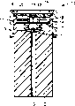
Figure 7 shows that a kind of embodiment that adopts the checkout gear of Figure 1 and Figure 2 type.Fig. 7 has represented a kind of profile that is assemblied in the Electronic Testing assembly 10 in the housing, and this Electronic Testing assembly can be placed in the disinfection cavity, so that determine the effectiveness of disinfection cycle.As mentioned below, in disinfection cycle, these test suite 10 work, so that measure two locational temperature, one is the temperature in the checkout gear, another then is the temperature on the interior datum mark of disinfection cavity.Then, the measurement result of those temperature is used to determine disinfection cycle, especially the air empty stage in the cycle whether effectively (that is, meeting certain above-mentioned requirements).
In test suite as shown in Figure 7, the end wall 4 of test suite 1 inwardly concaves, so that form a groove 11 that holds the electronic component of test cell.Those parts will be described below.Electronics groove 11 has a dismountable end cap 12, and this electronics groove can be positioned in the outer housing 13 of fixing on it by screw.Fixedly the time, outer housing 13 is close to electronics groove 11 with end cap 12, so that the latter is sealed.Outer housing 13 is to be made by a kind of structurally inflexible material, so that when it is stressed, it can get back to its original shape.For example, the carbon fibre reinforced plastic that can adopt any metal, glass fibre or have a softening temperature that is higher than 150 ℃ is made outer housing 13.
Can protect the element that is contained in electronics groove 11 inside by the vacuum in the groove, make it avoid the infringement of the thermal extremes in the disinfection cavity.For that purpose, electronics groove 11 comprises an one-way cock 14, reduces to predetermined value when following when the external pressure of groove 11, and this one-way cock is opened.Then, when evacuation in disinfection cavity when simultaneously test suite 10 is placed wherein, valve 14 is opened, so as in electronics groove 11 also evacuation.Electronics groove 11 is holding the pick off 7 of checkout gear 1, (being a temperature sensor in this example), and one second temperature sensor 15. Temperature sensor 7 and 15 can be the temperature divertor of any suitable type, for example thermocouple or critesistor.As mentioned above, temperature sensor 7 being set is terminal temperature for the vestibule 3 of measuring checkout gear 1.On the other hand, external temperature is measured in temperature sensor 15.So when being placed into Electronic Testing assembly 10 in the disinfection cavity, the temperature of disinfection cavity is measured in temperature sensor 15.
Groove 11 also comprises a circuit board 16, like this mounting circuit boards be for the cell wall that makes itself and groove heat insulation, to prevent that outside heat from conducting to the electronic component that is installed on the circuit board, it comprises a microprocessor and a memorizer, preferably an EEPROM (EEPROM).Surface, battery 18, temperature sensor 7 and 15, a light emitting diode 19 and a pressure transducer 20 that chip 17 is installed are electrically connected with circuit board 16.
When temperature was measured in temperature sensor 7 and 15, temperature reading was in the time data that comes from microprocessor is stored in the memorizer of test suite.In case microprocessor determines to have finished disinfection cycle, it determines whether (temperature reading that comes from storage) disinfection cycle is satisfactory, in other words is exactly the length whether disinfectant permeates the vestibule 3 in the checkout gear fully again then.
If it is satisfactory that microprocessor is determined disinfection cycle, then light emitting diode (LED) 19 is luminous.In the Electronic Testing assembly in being contained in a housing fully, only need one single led so that show whether by this cycle.Have under the single led situation, this LED can be luminous continuously to represent the cycle of a success, can also glimmer to represent the cycle of a failure.In addition, can adopt two LED to be expressed as the cycle of merit and the cycle of failure.If by disinfection cycle, then a LED sends green glow.Failed if microprocessor is determined this disinfection cycle, then another LED sends HONGGUANG.
In some cases, the data that preferably will be stored in the memorizer of this assembly are delivered to a ppu or memorizer or printer.Data are carried can be by making a magnetic force step switch (not shown), and preferably a reed switch moves and starts.
The mode that test suite 10 definite disinfection cycles are renderd a service will be introduced hereinafter tout court.As mentioned above, consult accompanying drawing 1, the hot attribute of checkout gear 1 is in the air empty stage in disinfection cycle, and an air pocket often will be trapped in the inner (blind end) of vestibule 3.Similarly, also often will be trapped in the inner of vestibule 3 by the non-condensing gas of entrainment with steam.The size in air cave has been represented the effectiveness of disinfection cycle, and when the air empty stage in the cycle was insufficient, air pocket tended to bigger.The air cave can stop under the effect fully that makes pick off 7 be exposed to disinfectant, so, between the temperature of the temperature of pick off 7 and pick off 15, produce the temperature difference.Test suite 10 determines whether this temperature difference above the predetermined value on the predetermined point in the disinfection cycle, if surpass, then this cycle is considered to not satisfied.This predetermined temperature difference is to be determined by the test that is identified, and in this test, the performance of Electronic Testing assembly is compared with the standard Bowie-Dick textile testing assembly that those meet the generally acknowledged world, Europe or national standard.For example, test suite can be programmed in advance, if so that reach after sterilization keeps 134 ℃ of temperature at cavity temperature, the temperature difference is higher than 2 ℃ in two minutes 40 seconds time, and then this cycle is considered to not satisfied.And cavity temperature must maintain on the adequately disinfected temperature, so that carry out disinfection.
During the information of the pick off 8 that provides heat to be penetrated into to be arranged in checkout gear 1 when the test (as described just now) of the temperature difference between outside and the internal temperature, it can directly not reflect the infiltration of disinfectant to pick off.By inferring that the rapid balance between induction point in checkout gear and the disinfection cavity represents not exist isolated air cave.Yet, in steam disinfecting apparatus, can directly measure the moisture that infiltrates into the induction point in the checkout gear.For that purpose, can replace temperature sensor or except temperature sensor 8, adopt moisture transducer such as conductivity sensor or relative humidity sensor, so that determine to infiltrate into the adequate water of the induction point in the checkout gear, thus, by inferring, determine steam.The temperature sensor 15 of measuring the disinfection cavity temperature keeps same situation.
Figure 3 shows that the checkout gear of another kind of form, it is similar to device illustrated in figures 1 and 2, and difference is that the cross section of vestibule 3 successively decreases towards the direction of pick off 7.
Figure 4 shows that a kind of checkout gear 24, wherein the wall 6 of vestibule 3 (though be still made by heat-barrier material) comes thinly than wall illustrated in figures 1 and 2, this wall have by wall 6 and around shell 20 between carry secretly that air provided was additional heat insulation.Shell 20 needn't be made by heat insulation material, such as, it can be made of metal.Shell 20 forms two parts, and a part (21) is fixed and is sealed on the flange 22 on every side of a vestibule 3 openings.The second portion 23 of shell 20 is end caps, and it is fixed together with screw thread and first, so that can pull down this end cap, so that can be near the pick off 7 on the blind end that is positioned at vestibule 3.Interface between two parts 21 and 23 of shell 20 also seals.
In checkout gear shown in Figure 4, the space 26 between wall 6 and the shell 20 can hold the heat insulation packing material of certain form, such as a kind of heat-insulating foam material or glass fibre.In addition, this space can be evacuated.
Structure as shown in Figure 4 can combine use with different materials, and a kind of checkout gear can be provided, and this checkout gear has the hot attribute identical with device shown in Figure 1, is that this checkout gear has less external dimensions.In this structure, the wall 6 of vestibule has constituted the radiator portion of device and since around the gas compartment 26, therefore when this device was positioned at a disinfector, this radiator portion came from preferential absorption the heat of vestibule 3.
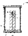
Fig. 8 and the embodiment that Figure 9 shows that the checkout gear that adopts type shown in Figure 4.Figure 8 shows that a kind of test suite 30, this test suite is made of a checkout gear shown in Figure 4 24 and an end cap 31, this end cap is supporting a biological display 32, be installed on the checkout gear and be positioned at opening when top of vestibule 3 with this end cap 31 of box lunch, this display 32 is positioned on the blind end of vestibule.Display 32 can be the biological display of any suitable type, such as, the trade mark of being made by the 3M company of St.Paul, Minnesota is a kind of display of " ATTEST ".This end cap 31 has the disinfectant of making and enters into aperture 33 in the vestibule 3 from the outside of test suite 30.
When disinfection cycle begins, this test suite 30 is placed in the disinfection cavity, and when this cycle has finished, it is taken out.Then, display 32 is taken out in checkout gear, and carry out above-mentioned processing, so that whether make it can demonstrate this disinfection cycle effective.Certainly, another display 32 of can packing in this checkout gear then, and reuse.
Figure 9 shows that a kind of test suite 35, this test suite is similar to test suite shown in Figure 8, and difference only is that it has a chemical indicator, rather than a biological display.As shown in the figure, this chemical indicator is narrow strip 36 (comprising that has the substrate of the responsive printing ink of disinfectant), and this fillet extends along the length of vestibule 3.A kind of suitable chemical indicator is the trade mark made by the 3M company of the St.Paul, Minnesota chemical indicator for " Comply 1250 ".
Also be when disinfection cycle begins, this test suite 35 to be placed in the disinfection cavity, and when this cycle has finished, it taken out.Then, display fillet 36 is taken out in checkout gear, and check the change color that length took place along fillet, this will demonstrate disinfectant at once and be penetrated into what degree along vestibule 3, and whether this disinfection cycle is effective.Certainly, another display fillet 36 of can packing in this checkout gear then, and reuse.
Figure 5 shows that another kind of checkout gear, this checkout gear is similar to device shown in Figure 4, and difference is that it is equipped with a plurality of pick offs, and is not only a single-sensor.Figure 5 shows that this device has four pick offs, but also can adopt the pick off of any right quantity.Pick off 40 is positioned on the different points along the length of vestibule 3, and one of them pick off is the blind end place at vestibule, and this is corresponding with pick off 7 shown in Figure 2.In disinfection cycle, the parameter that is detected by pick off 40 will demonstrate in this cycle, be penetrated into what degree along the vestibule 3 of checkout gear in the different moment, disinfectant, whether effective, the record of disinfector work can be provided if also demonstrating this disinfection cycle in addition.
Each by Fig. 1 to the checkout gear shown in Figure 5, the wall of vestibule 3 is straight and successive, but this is not necessary.For example, vestibule 3 can be along a spirality channel, and adjacent spiral is heat insulation mutually in this spirality channel.The length overall that this spirality channel can reduce checkout gear is set.As another interchangeable form, can form a series of contraction structures along vestibule, the concretion that does not wherein have a kind of contraction structure to be formed in disinfection cycle blocks, and they can not eliminate the opening 5 separated free spaces with pick off 7 and vestibule.Figure 6 shows that a kind of checkout gear of the above-mentioned type.Checkout gear 45 shown in Figure 6 is similar substantially to checkout gear shown in Figure 4, difference only is to exist several walls with holes 46 on some points of the length of vestibule 3, and these walls with holes are separated into vestibule the compartment 47 of a series of connections effectively.The compartment that is positioned on the end of vestibule 3 has opening 5, and disinfectant promptly enters into checkout gear by this opening, and the compartment that is positioned on the other end of vestibule 3 is equipped with pick off 7.Additional temperature sensor can be provided, these temperature sensors can be installed in the identical compartment 47 on demand, also can be installed in one or more other compartments 47.Checkout gear shown in Figure 6 will be carrying out work to those Fig. 1 to the similar working method of device shown in Figure 5, but it will present different operating characteristic.
For the linear compartment 47 shown in Figure 6 a replacement form can be arranged, being about to a compartment is placed in another compartment, the opening 5 that is used for disinfectant is in the compartment of this structural outer, and pick off 7 then is installed in the locational compartment of this structure centre.Each compartment is heat insulation separately, so that heat can be passed to pick off 7 from opening 5 by the free space in all compartments, rather than transmits by the wall of the compartment.
Each by Fig. 1 to the checkout gear shown in Figure 6, interior bore or chamber 3 required hot attributes are that the wall by single heat-barrier material provides.Yet, equivalent hot attribute can also be provided with the wall of composite construction, the wall of these composite constructions can comprise Heat Conduction Material and heat-barrier material.For example, the checkout gear of type illustrated in figures 1 and 2 can have one or more parts, and these parts are to be made with the material with relative high thermal that heat-barrier material combines by a kind of, so that required hot attribute is provided.When the material with relative high thermal exists, guarantee carefully that it can not cause any substantive the increasing of transmitting at heat on the longitudinal direction of the wall of vestibule 3.In addition, if keep with pick off 7 and vestibule opening 5 separated free spaces, and narrowless the attending the meeting of this free space blocked by formed concretion in decontamination cycle, in the checkout gear of type shown in Figure 6, can obtain required hot attribute by the heat-barrier material that uses the wall that is used for the compartment 47 that combines with radiator (higher thermal capacitance gauge block) in the compartment.
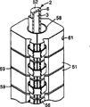
Figure 10 shows that a kind of checkout gear 50, this checkout gear is similar substantially to device 19 shown in Figure 4, difference only be the thermal wall of pipe 2 be by 51 of several length localized heat-conducting blocks arranged side by side along pipe around.As shown in Figure 4, checkout gear 50 has one around shell 25, and as shown in figure 10, an end of this shell is opening wide, but in use, this shell outfit one and end cap 23 corresponding end plates shown in Figure 4 are so that provide a sealing.In Figure 10, only see the blind end 52 of pipe 2.Can be by an end plate 53 near the vestibule 3 that is arranged in pipe 2, this end plate 53 surrounds the opening of pipe, and is supporting heat-conducting block 51 and shell 25.The one optional heat insulation cylinder of being made by perforated foams 64 is around heat-conducting block 51, and is positioned at the inside of shell 25.
To describe the structure (the especially structure of pipe 2 and heat-conducting block 51) of device 50 in conjunction with Figure 11 and Figure 12 in detail now, only show the part of this device among the figure near the blind end of pipe 2.In Figure 11, pull down the heat-conducting block 51 of the blind end 52 of the most close pipe 2, in Figure 12, then ignored this heat-conducting block 51 fully.
The cross section of the vestibule 3 (as shown in figure 12) of pipe 2 is circular, but except the part of the most close blind end 52, the external cross section of pipe is orthogonal.The heat-conducting block 51 that forms the radiator portion of this device is positioned on the square-section part of pipe 2, and each heat-conducting block is divided into two five equilibriums 54, and each part has the corresponding smooth inner surface 55 in two outsides with pipe.When on the appropriate location of pipe 2, two parts 54 of each heat-conducting block 51 are clipped together by two alligator clamps 56, groove 57 engagements on these two alligator clamps and the heat-conducting block outer surface.The interior shape of the rectangular profile of pipe 2 and heat-conducting block 51 correspondences provides thermo-contact good between pipe and the heat-conducting block, when checkout gear 50 in use is positioned at disinfection cavity, alligator clamp 56 guarantees to keep good thermo-contact in the different rates that adapts to the expansion of pipe and heat-conducting block and shrink.
Though heat-conducting block 51 is placed side by side along the length of pipe 2, be discontiguous between they are mutual, but separate slightly by heat insulation O shape ring 58 (as the Figure 11 and shown in Figure 12) between the adjacent heat-conducting block.Gas gap 59 between the resulting heat-conducting block makes heat-conducting block heat insulation between mutually, and prevent heat along the length direction of pipe 2 by the heat-conducting block transmission.When all heat-conducting blocks 51 were positioned on the appropriate location of pipe 2, they were fixing on the throne by 60 (as shown in figure 10) of circle folder, and this circle folder is installed on the end near the heat-conducting block of tube end.
Penult heat-conducting block 51 on the pipe 2 has a circular open 61, when using this checkout gear, a temperature sensor, preferably a platinum resistance thermometer (PRT) is installed in this circular open.In Figure 10, can see the electric lead 62 of this temperature sensor.This temperature sensor has substituted the temperature sensor 7 in the checkout gear 19 shown in Figure 4, and be different from that temperature sensor be, this temperature sensor is not to be positioned at the vestibule of pipe 23, but is positioned at one of them heat-conducting block 51 around the blind end of pipe pipe, close.Certainly, also can use the temperature sensor of other pattern.
This checkout gear 50 can use in determining the test suite that disinfection cycle is renderd a service by the same way as of the checkout gear of above-mentioned any kind.Especially, this checkout gear 50 can be used in the test suite of type shown in Figure 7, except checkout gear, also be provided with one second temperature sensor (promptly in use with the external temperature of measuring test suite, the interior temperature of disinfection cavity that test suite is wherein arranged), and according to the measurement result of temperature sensor, the circuit of test suite is worked in mode shown in Figure 7, so that determine whether disinfection cycle is satisfactory.In order to use this test suite, checkout gear 50 has possessed one second temperature sensor, this second temperature sensor is used for measuring the external temperature of test suite, the electric lead 63 of this second temperature sensor as shown in figure 10, this electric lead extends in the space between shell 25 and heat-conducting block 51.
In disinfection cycle, disinfectant has only by the lower end of pipe 2 (opening) and just can enter in the vestibule 3 of checkout gear 50.Because pipe 2 because the space in the shell 2 (and when having heat insulation cylinder 64, also because this cylindrical cause) with the interior heat of disinfection cavity be heat insulation, and because the wall 6 of vestibule 3 make by heat-barrier material, so vestibule 3 will absorb the heat that enters into the interior disinfectant of this vestibule at first.Therefore, the temperature of wall 6 will remain under the temperature of disinfection cavity, and the disinfectant that enters in the vestibule will condense on wall 6, not be penetrated into the end of vestibule 3 at once, cause air or non-condensing gas buildup thus in vestibule.The same with above-mentioned other checkout gear, use this checkout gear 50 according to direction as shown in the figure, even the opening of vestibule 3 points to down, so that can in disinfection cycle, discharge the concretion that is formed in the vestibule.The air pocket or the non-condensing gas caves that are formed in the vestibule 3 will suppress the end that disinfectant is penetrated into vestibule, and will influence pipe 2 blind end temperature and around the interior temperature of heat-conducting block 51.In this respect, be noted that heat-conducting block 51 can prevent to transmit mutually heat by gas gap 59.Therefore, the temperature of the heat-conducting block 51 of the blind end by being positioned at pipe 2 with respect to the temperature survey in the disinfection cavity, can determine whether that disinfectant has infiltrated into the end of pipe (representing that this disinfection cycle is effective), perhaps air pocket or non-condensing gas cave remain on the end of pipe (representing that this disinfection cycle is invalid).
The heat-barrier material of making pipe 2 can be steam tight, and is stable under the condition that is run in disinfection cavity.Heat-barrier material is preferably liquid crystal polymer (LCP), preferably contains the Wholly aromatic copolymer of the graphite of 25% percentage by weight.The Heat Conduction Material of making heat-conducting block 51 is aluminum preferably.O shape ring 58 between heat-conducting block can be made by rubber, and the shell 25 of device can be made by rustless steel.Pipe 2 length are generally 115 millimeter, and its internal diameter (that is, the diameter of vestibule) is approximately 6 millimeters, and its external dimensions is approximately 10 millimeters square.Heat-conducting block 51 is generally about 28 millimeters square, and its width is approximately 15 millimeters.As shown in the figure, adopted six such heat-conducting blocks among the figure, the gap 59 between the adjacent heat-conducting block is approximately 1 millimeter.In addition, also can adopt the more thin heat-conducting block (for example, adopting 12 heat-conducting blocks of 7 mm wides) of number.
Be appreciated that Fig. 3 to Fig. 6 and any checkout gear shown in Figure 10 can use in test suite shown in Figure 7 (rather than device illustrated in figures 1 and 2).Similarly, checkout gear not only shown in Figure 4 can use as Fig. 8 and mode shown in Figure 9: and any other checkout gear of having described all can use according to the sort of mode.
Usually, the checkout gear that has been found that type as shown in the figure in disinfection cycle, the condition that is present in the variation in the disinfection cavity has some delayed action.When a checkout gear uses in a test suite, and decontamination cycle renderd a service when sending the judgement of one simple " success/failure ", because this judgement is to be based upon on the situation of the late phase in cycle, rather than is based upon on the situation of initial period, so think that this phenomenon is very important.Have been found that especially that when adopting the checkout gear of type shown in Figure 10 " success/failure " judgement reliably only is based upon on the measurement result of temperature, and the measurement of humidity is not essential.Think that this is favourable, make the temperature sensor of various high-reliabilities have availability widely.In addition, for making " success/failure " reliably judgement, be not critical in the exact position of finding pick off in the device shown in Figure 10 especially.
Though as its preferable orientation that is orientated of Fig. 1 to Fig. 6 and checkout gear shown in Figure 10, this is that the sort of orientation is not most important because orientation can make concretion discharge in vestibule 3 like this.As further modification, can contain the absorbent material of some form on the vestibule wall.
Equally, though above description relates to the checkout gear that uses in disinfection cavity, this is optional equally.The checkout gear of the above-mentioned type also can be installed in the outside (for example, being connected to drain pipe) of disinfector, and the opening 5 of vestibule 3 communicates with the inside of disinfection cavity by a suitable connector.
Claims (18)
1. a use is used for determining the disinfectant checkout gear of effectiveness of the air empty stage of disinfection cycle in disinfector, and described device comprises that one constitutes the chamber of a free space; One is used for the opening that disinfectant enters into described free space; One radiator portion, when described device used in a disinfector, described radiator portion preferential absorption came from the heat of described free space; And be used to install a pick off to detect the device that exists of disinfectant on the described opening of distance precalculated position far away, that be positioned at described free space, the wall in described chamber contains heat-barrier material, described heat-barrier material has stoped the heat that comes from the described disinfector to be passed to described free space by the wall in chamber, thereby in disinfection cycle, by by hydrogenesis caused accumulation that is positioned at the air and/or the non-condensing gas of described free space on the wall in chamber, suppressed to come from of the infiltration of the disinfectant of described opening to described precalculated position.
2. device as claimed in claim 1 is characterized in that described chamber is formed in the described radiator portion.
3. device as claimed in claim 1 or 2 is characterized in that, described radiator portion by an insulating portion around, thereby in disinfection cycle, described radiator portion comes from preferential absorption the heat of described free space.
4. device as claimed in claim 3 is characterized in that described insulating portion comprises a shell, and described shell is around described radiator portion, and separates with described radiator portion, and a kind of heat-barrier material is contained in described space.
5. device as claimed in claim 3 is characterized in that described insulating portion comprises a shell, and described shell is around described radiator portion, and separates by a space and described radiator portion.
6. as the described device of any one claim in the above-mentioned claim, it is characterized in that described radiator portion is made by heat-barrier material.
7. as the described device of any one claim in the claim 1 to 5, it is characterized in that described radiator portion comprises Heat Conduction Material.
8. as the described device of any one claim in the claim 1 to 5, it is characterized in that, described chamber is a passage of end sealing, and described precalculated position is near the described blind end of described passage, and is used for the other end that described opening that disinfectant enters is positioned at described passage.
9. device as claimed in claim 8 is characterized in that, described passage is the vestibule that is positioned at the pipe of a heat-barrier material, and described radiator portion comprises a heat carrier around described pipe.
10. device as claimed in claim 9 is characterized in that, described radiator portion comprises some length along described pipe around the localized heat carrier of pipe, and described heat carrier is heat insulation mutually.
11. device as claimed in claim 10, it is characterized in that, comprise a temperature sensor, described temperature sensor is set is in order to detect, thereby detect the existence of adjacent domain disinfectant of the vestibule of described pipe on the described pipe blind end or near the temperature on wherein a slice heat carrier of described blind end.
12. device as claimed in claim 8 is characterized in that, described passage is made by many heat-barrier materials.
13. device as claimed in claim 12 is characterized in that, comprises a temperature sensor, it is in order to detect on the blind end of described passage or the existence of approaching described blind end disinfectant that described temperature sensor is set.
14. device as claimed in claim 8, it is characterized in that, described passage comprises the partitioned portion of several intercommunications, is used for the partitioned portion that described opening that disinfectant enters is positioned at one of them intercommunication, and described precalculated position then is positioned on the partitioned portion of another intercommunication.
15. a use is used for determining the disinfectant checkout gear of effectiveness of the air empty stage of disinfection cycle in disinfector, described device comprises the pipe of a heat-barrier material, constitute the vestibule of the described pipe of a free space, for making disinfectant can enter described vestibule in the upper shed of one end, the other end then seals; Some length along described pipe are around the localized heat carrier of pipe, and described heat carrier is heat insulation mutually; And around the insulating portion of described pipe and heat carrier, thereby in disinfection cycle, by by hydrogenesis caused accumulation that is positioned at the air and/or the non-condensing gas of described free space on the wall of vestibule, suppressed the infiltration of disinfectant along the vestibule of described pipe, described device also comprises and is used to install a pick off to detect existing on the blind end of described pipe or near described blind end disinfectant.
16. device as claimed in claim 15, it is characterized in that, comprise a temperature sensor, described temperature sensor is installed on the blind end of described pipe or near on one of them heat carrier of described blind end, so that detect the temperature on the described heat carrier, thereby detect the existence of adjacent domain disinfectant of the vestibule of described pipe.
17., it is characterized in that as claim 15 or 16 described devices, provided by a shell around the insulating portion of described pipe and heat carrier, described shell is around described pipe and heat carrier, and therefrom separated by a space.
18. device as claimed in claim 16 is characterized in that, also is used in combination one second temperature sensor, it is in order to detect the temperature of the disinfection cavity that described device wherein is housed that described second temperature sensor is set.
Applications Claiming Priority (2)
| Application Number | Priority Date | Filing Date | Title |
|---|---|---|---|
| EP95202692.0 | 1995-10-06 | ||
| EP95202692 | 1995-10-06 |
Publications (1)
| Publication Number | Publication Date |
|---|---|
| CN1198678A true CN1198678A (en) | 1998-11-11 |
Family
ID=8220692
Family Applications (1)
| Application Number | Title | Priority Date | Filing Date |
|---|---|---|---|
| CN96197352.8A Pending CN1198678A (en) | 1995-10-06 | 1996-10-07 | Sterilizer testing systems |
Country Status (9)
| Country | Link |
|---|---|
| US (1) | US20020034823A1 (en) |
| EP (2) | EP1172117A3 (en) |
| JP (1) | JP3858081B2 (en) |
| CN (1) | CN1198678A (en) |
| AU (1) | AU715489B2 (en) |
| CA (1) | CA2231247A1 (en) |
| DE (1) | DE69620209T2 (en) |
| ES (1) | ES2175140T3 (en) |
| WO (1) | WO1997012637A1 (en) |
Cited By (6)
| Publication number | Priority date | Publication date | Assignee | Title |
|---|---|---|---|---|
| CN102256631A (en) * | 2008-10-17 | 2011-11-23 | 3M创新有限公司 | Biological sterilization indicator, system, and methods of using same |
| CN103096938A (en) * | 2010-09-17 | 2013-05-08 | 3M创新有限公司 | Device and method for determining sterilization conditions |
| CN104812417A (en) * | 2012-09-18 | 2015-07-29 | 3M创新有限公司 | Measurement of the ncg concentration in a steam sterilizer |
| CN104780947B (en) * | 2012-09-18 | 2017-11-14 | 3M创新有限公司 | Disinfectant identification device |
| CN111683691A (en) * | 2018-02-06 | 2020-09-18 | 恩德斯+豪斯流量技术股份有限公司 | Method and device for detecting a non-condensable portion of an at least partially gaseous medium |
| CN111714669A (en) * | 2014-03-11 | 2020-09-29 | 史赛克公司 | Sterilization container with battery-powered sensor module for monitoring the environment within the container |
Families Citing this family (22)
| Publication number | Priority date | Publication date | Assignee | Title |
|---|---|---|---|---|
| US6323032B1 (en) | 1996-10-07 | 2001-11-27 | 3M Innovative Properties Company | Sterilizer testing systems |
| GB9727533D0 (en) * | 1997-12-22 | 1998-02-25 | Minnesota Mining & Mfg | Housing for a sterilization monitoring device |
| GB9820029D0 (en) * | 1997-12-22 | 1998-11-04 | Minnesota Mining & Mfg | Sterilant challenge device for a sterilization monitoring system |
| US6630352B1 (en) | 1997-12-22 | 2003-10-07 | 3M Innovative Properties Company | Sterilant challenge device for a sterilization monitoring system |
| DE19944847C1 (en) * | 1999-09-18 | 2001-05-03 | Secundus Medizinische Kontroll | Sterilization test device |
| US7091042B2 (en) * | 2001-11-02 | 2006-08-15 | Ethicon, Inc. | Variable resistance sterilization process challenge device and method |
| DE20201752U1 (en) * | 2002-02-05 | 2002-04-18 | HS System- und Prozesstechnik GmbH, 65779 Kelkheim | Measuring device for monitoring sterilization conditions |
| US7193519B2 (en) * | 2002-03-18 | 2007-03-20 | Optim, Inc. | Reusable instruments and related systems and methods |
| DE50300631D1 (en) | 2003-03-28 | 2005-07-14 | Kaiser Ulrich | Test specimens, in particular for checking the penetration properties of a sterilizing agent in sterilization processes |
| US7163305B2 (en) | 2003-06-25 | 2007-01-16 | Gemtron Corporation | Illuminated shelf |
| DE202006006926U1 (en) | 2006-04-29 | 2006-06-29 | Ebro Electronic Gmbh & Co. Kg | Device for testing effectiveness of autoclave steam sterilization, e.g. of medical articles, via temperature measurements, including sensors in sterilization zone and removable, easily cleaned measuring chamber |
| US7718125B2 (en) | 2007-07-25 | 2010-05-18 | Dana Products Inc. | Sterilization challenge specimen holder |
| US7790105B2 (en) * | 2007-07-25 | 2010-09-07 | Dana Prodicts, Inc. | Sterilization challenge specimen holder |
| FR2950810B1 (en) * | 2009-10-02 | 2012-12-07 | Sterlab | TEST DEVICE FOR MONITORING STERILIZING APPARATUS PREVIDED BY WATER VAPOR |
| CA3122224C (en) * | 2013-03-13 | 2023-12-05 | Stryker Corporation | Sterilization container capable of providing an indication regarding whether or not surgical instruments sterilized in the container were properly sterilized |
| JP6489423B2 (en) * | 2015-02-06 | 2019-03-27 | 三浦工業株式会社 | Process test device and steam sterilizer equipped with the same |
| JP6555477B2 (en) * | 2015-11-02 | 2019-08-07 | 三浦工業株式会社 | Air leak detector and steam sterilizer equipped with the same |
| FR3061435B1 (en) * | 2017-01-05 | 2019-05-24 | Peugeot Citroen Automobiles Sa | METHOD AND SYSTEM FOR MEASURING THE EFFICIENCY OF A DEVICE FOR DISINFECTING A VEHICLE |
| NL2018932B1 (en) * | 2017-05-17 | 2018-11-28 | Solidtoo B V | Monitoring of steam quality during sterilization |
| US20210290810A1 (en) | 2018-08-21 | 2021-09-23 | Gke Gmbh | Multi-stage process challenge device, indicator system and process challenge device system |
| DE102020122960A1 (en) * | 2020-09-02 | 2022-03-03 | Jointinventions Gmbh | Method for detecting disinfection, test kit therefor and disinfection method |
| CN112423499A (en) * | 2020-10-26 | 2021-02-26 | 常州市盛霆机械有限公司 | Epidemic prevention cabinet assembly |
Family Cites Families (3)
| Publication number | Priority date | Publication date | Assignee | Title |
|---|---|---|---|---|
| US4115068A (en) * | 1977-04-06 | 1978-09-19 | Sybron Corporation | Air detecting device for steam or gas sterilizers |
| US4594223A (en) * | 1984-12-20 | 1986-06-10 | American Sterilizer Company | Device for detecting the presence of noncondensable gas in steam sterilizers |
| WO1993021964A1 (en) * | 1992-05-05 | 1993-11-11 | Colvin Richard R | Sterilizer test method and apparatus |
-
1996
- 1996-10-07 EP EP01121554A patent/EP1172117A3/en not_active Withdrawn
- 1996-10-07 EP EP96937663A patent/EP0854733B1/en not_active Expired - Lifetime
- 1996-10-07 ES ES96937663T patent/ES2175140T3/en not_active Expired - Lifetime
- 1996-10-07 JP JP51451197A patent/JP3858081B2/en not_active Expired - Fee Related
- 1996-10-07 DE DE69620209T patent/DE69620209T2/en not_active Expired - Lifetime
- 1996-10-07 CN CN96197352.8A patent/CN1198678A/en active Pending
- 1996-10-07 AU AU75151/96A patent/AU715489B2/en not_active Ceased
- 1996-10-07 CA CA002231247A patent/CA2231247A1/en not_active Abandoned
- 1996-10-07 WO PCT/US1996/016054 patent/WO1997012637A1/en active IP Right Grant
-
2001
- 2001-11-27 US US09/995,455 patent/US20020034823A1/en not_active Abandoned
Cited By (10)
| Publication number | Priority date | Publication date | Assignee | Title |
|---|---|---|---|---|
| CN102256631A (en) * | 2008-10-17 | 2011-11-23 | 3M创新有限公司 | Biological sterilization indicator, system, and methods of using same |
| CN102256631B (en) * | 2008-10-17 | 2014-07-23 | 3M创新有限公司 | Biological sterilization indicator, system, and methods of using same |
| CN103096938A (en) * | 2010-09-17 | 2013-05-08 | 3M创新有限公司 | Device and method for determining sterilization conditions |
| CN103096938B (en) * | 2010-09-17 | 2016-02-10 | 3M创新有限公司 | Determine the apparatus and method of sterilising conditions |
| CN104812417A (en) * | 2012-09-18 | 2015-07-29 | 3M创新有限公司 | Measurement of the ncg concentration in a steam sterilizer |
| CN104780947B (en) * | 2012-09-18 | 2017-11-14 | 3M创新有限公司 | Disinfectant identification device |
| CN111714669A (en) * | 2014-03-11 | 2020-09-29 | 史赛克公司 | Sterilization container with battery-powered sensor module for monitoring the environment within the container |
| CN114796539A (en) * | 2014-03-11 | 2022-07-29 | 史赛克公司 | Sterilization container with battery-powered sensor module for monitoring the environment within the container |
| CN111683691A (en) * | 2018-02-06 | 2020-09-18 | 恩德斯+豪斯流量技术股份有限公司 | Method and device for detecting a non-condensable portion of an at least partially gaseous medium |
| US11747293B2 (en) | 2018-02-06 | 2023-09-05 | Endress+Hauser Flowtec Ag | Method and device for detecting a non-condensable portion of a medium which is at least in part gaseous |
Also Published As
| Publication number | Publication date |
|---|---|
| DE69620209D1 (en) | 2002-05-02 |
| JP3858081B2 (en) | 2006-12-13 |
| EP1172117A2 (en) | 2002-01-16 |
| CA2231247A1 (en) | 1997-04-10 |
| EP0854733A1 (en) | 1998-07-29 |
| JPH11513285A (en) | 1999-11-16 |
| AU7515196A (en) | 1997-04-28 |
| ES2175140T3 (en) | 2002-11-16 |
| AU715489B2 (en) | 2000-02-03 |
| EP1172117A3 (en) | 2002-07-24 |
| DE69620209T2 (en) | 2002-11-07 |
| WO1997012637A1 (en) | 1997-04-10 |
| US20020034823A1 (en) | 2002-03-21 |
| EP0854733B1 (en) | 2002-03-27 |
Similar Documents
| Publication | Publication Date | Title |
|---|---|---|
| CN1198678A (en) | Sterilizer testing systems | |
| CN1249429C (en) | Humidity sensor | |
| EP1025863B1 (en) | Electronic test pack using parametric measurements for sterilizers | |
| CA2135198C (en) | Sterilizer test method and apparatus | |
| US4115068A (en) | Air detecting device for steam or gas sterilizers | |
| US5834313A (en) | Container monitoring system | |
| JPH03121072A (en) | Disposable test pack for steam or gas type sterilizer | |
| WO2014046998A1 (en) | Measurement of the ncg concentration in a steam sterilizer | |
| CN108066789A (en) | UV sterilizer and its method of work | |
| CN110743024A (en) | Steam cycle sterilization cabinet | |
| US6630352B1 (en) | Sterilant challenge device for a sterilization monitoring system | |
| EP0776669A1 (en) | Testpack for sterilizers | |
| AU753062B2 (en) | Sterilant challenge device for a sterilization monitoring system | |
| CN112469448A (en) | Multi-stage process challenge device, indicator system and process challenge device system | |
| JP6254167B2 (en) | Sterilizer inspection device | |
| CN215555232U (en) | Intelligent temperature control purification type medicine storage equipment | |
| US5478749A (en) | Method and article for providing an indication of the presence of air in steam | |
| US20040086874A1 (en) | Devices and methods for holding a biopolymeric array | |
| MXPA98002061A (en) | Systems to test the sterilized | |
| CN108386991A (en) | Water collector and air conditioner | |
| CN211204701U (en) | Drying equipment of chinese-medicinal material | |
| EP4083587A1 (en) | Steam quality sensing device and method for monitoring a steam quality | |
| CN215825297U (en) | A dampproofing storage frame for depositing metal film of detecting a flaw | |
| CN110466869B (en) | Sample storage device | |
| CN210193869U (en) | Gene detection is with dry test tube of pharynx swab |
Legal Events
| Date | Code | Title | Description |
|---|---|---|---|
| C06 | Publication | ||
| PB01 | Publication | ||
| C10 | Entry into substantive examination | ||
| SE01 | Entry into force of request for substantive examination | ||
| C01 | Deemed withdrawal of patent application (patent law 1993) | ||
| WD01 | Invention patent application deemed withdrawn after publication |