CN1190613C - Device for producing pipe coupling - Google Patents
Device for producing pipe coupling Download PDFInfo
- Publication number
- CN1190613C CN1190613C CNB008165076A CN00816507A CN1190613C CN 1190613 C CN1190613 C CN 1190613C CN B008165076 A CNB008165076 A CN B008165076A CN 00816507 A CN00816507 A CN 00816507A CN 1190613 C CN1190613 C CN 1190613C
- Authority
- CN
- China
- Prior art keywords
- hold
- ring
- down ring
- connecting sleeve
- press
- Prior art date
- Legal status (The legal status is an assumption and is not a legal conclusion. Google has not performed a legal analysis and makes no representation as to the accuracy of the status listed.)
- Expired - Fee Related
Links
Images


Classifications
-
- F—MECHANICAL ENGINEERING; LIGHTING; HEATING; WEAPONS; BLASTING
- F16—ENGINEERING ELEMENTS AND UNITS; GENERAL MEASURES FOR PRODUCING AND MAINTAINING EFFECTIVE FUNCTIONING OF MACHINES OR INSTALLATIONS; THERMAL INSULATION IN GENERAL
- F16L—PIPES; JOINTS OR FITTINGS FOR PIPES; SUPPORTS FOR PIPES, CABLES OR PROTECTIVE TUBING; MEANS FOR THERMAL INSULATION IN GENERAL
- F16L13/00—Non-disconnectible pipe-joints, e.g. soldered, adhesive or caulked joints
- F16L13/14—Non-disconnectible pipe-joints, e.g. soldered, adhesive or caulked joints made by plastically deforming the material of the pipe, e.g. by flanging, rolling
- F16L13/141—Non-disconnectible pipe-joints, e.g. soldered, adhesive or caulked joints made by plastically deforming the material of the pipe, e.g. by flanging, rolling by crimping or rolling from the outside
-
- B—PERFORMING OPERATIONS; TRANSPORTING
- B21—MECHANICAL METAL-WORKING WITHOUT ESSENTIALLY REMOVING MATERIAL; PUNCHING METAL
- B21D—WORKING OR PROCESSING OF SHEET METAL OR METAL TUBES, RODS OR PROFILES WITHOUT ESSENTIALLY REMOVING MATERIAL; PUNCHING METAL
- B21D39/00—Application of procedures in order to connect objects or parts, e.g. coating with sheet metal otherwise than by plating; Tube expanders
- B21D39/04—Application of procedures in order to connect objects or parts, e.g. coating with sheet metal otherwise than by plating; Tube expanders of tubes with tubes; of tubes with rods
-
- F—MECHANICAL ENGINEERING; LIGHTING; HEATING; WEAPONS; BLASTING
- F16—ENGINEERING ELEMENTS AND UNITS; GENERAL MEASURES FOR PRODUCING AND MAINTAINING EFFECTIVE FUNCTIONING OF MACHINES OR INSTALLATIONS; THERMAL INSULATION IN GENERAL
- F16L—PIPES; JOINTS OR FITTINGS FOR PIPES; SUPPORTS FOR PIPES, CABLES OR PROTECTIVE TUBING; MEANS FOR THERMAL INSULATION IN GENERAL
- F16L13/00—Non-disconnectible pipe-joints, e.g. soldered, adhesive or caulked joints
- F16L13/14—Non-disconnectible pipe-joints, e.g. soldered, adhesive or caulked joints made by plastically deforming the material of the pipe, e.g. by flanging, rolling
- F16L13/146—Non-disconnectible pipe-joints, e.g. soldered, adhesive or caulked joints made by plastically deforming the material of the pipe, e.g. by flanging, rolling by an axially moveable sleeve
Abstract
The invention relates to a device for producing a pipe coupling (1) at two pipe ends (4). The objective of the invention is to produce a pressure-tight pipe connection by applying axial pressure, thereby guaranteeing maximum universality regarding the specifications of the quality of the pipes that are tio be connected. Said device for producing a pressure-tight pipe coupling with at least one pipe end comprises a bushing-type, rotationally symmetric base body. The base body (2) is provided with at least one essentially cylindrical inner chamber, having toothed elements (6,7) in order to receive the pipe end. The toothed elements are displaced radially into the pipe end arranged in the inner chamber by means of a pressing device (6) which impinges upon the outer surface of the base body. A pressing device (10) consisting of a shaping ring and a corresponding pair of shaping rings (12,13) guarantee that the radial displacement potential is realized in the form of a radial displacement, resulting in significantly lower pressing power.
Description
Technical field
The present invention relates to the device that a kind of pipe of setting up two pipe ends connects, particularly surround the matrix of pipe end and the assembling pipe joint that a hold down gag that surrounds matrix is formed by one at least.Wherein make the matrix radial compaction on pipe surface by moving axially of hold down gag.
Background technique
By US-PS3,827,727; US-PS3,893,720; US-PS4,026,006; US-PS4,061,367; US-PS4,482,174; US-PS5, the assembling pipe joint of this principle of 110,163 known employings.
The shortcoming of this assembling pipe joint is that it is restricted in its function aspects owing to the height of pipe diameter, the quality requirement for the treatment of connecting tube and pressure medium in use.The Mechanical Builds of the extruding potential energy that forms in this external this assembling pipe joint must not be tightly connected unwanted, the material lateral extrusion of wishing except causing to reaching, also cause the axial compression of material, it does not have any help for being tightly connected, but the impacting force that need apply from the outside is produced such influence, make impacting force surpass for the necessary degree of the radial compaction of material.No matter to be each size of component of pressurizing tool or assembling pipe joint excessive thereby cause from the beginning.
Summary of the invention
The objective of the invention is, cause the pipeline of sealing to connect by axial compression, it guarantees the best versatility aspect the quality requirement of pipeline to be connected.
Another object of the present invention is, by the pipeline that adopts material common on the common market to form by extremely different, for example welded pipe is tightly connected even also set up in the zone of high pressure when having the relevant therewith franchise aspect mechanical property and length dimension.
Next an object of the present invention is, and reduces for the needed power of the axial compression of clamping element, thereby also reduce to be pressed into the required power that applies of pipe surface when maximum compression distance.
According to a first aspect of the invention, described purpose can realize with the device that the seal for pipe joints of at least one pipe end is connected by a foundation, described device is made up of the rotation symmetry matrix of a sleeve shape, wherein matrix has that at least one is columniform basically, is equipped with the inner chamber that is used for the pipe laying end of tooth-shape structure, tooth-shape structure by means of acting on hold down gag on the outer surface of matrix radial compaction on the surface of the pipe end of admitting by inner chamber, and
Matrix is made up of the connecting sleeve of the first-class substantially wall thickness of a hollow cylinder, wherein is being provided with at least two radial ringed tooth portions of contracting after being spaced from each other internal diameter certain distance, with respect to connecting sleeve on the connecting sleeve inwall.On the outside of connecting sleeve, form radial ringed and a plurality of tooth portion relative, width is equivalent to the level and smooth position structure of tooth portion width, and
One hold-down ring that can move on ground concentric above the connecting sleeve is used for covering connecting sleeve on its almost whole length, wherein hold-down ring has the radial ringed projection that matches with position structure within it on the side, and on its outside, have from the hold-down ring two ends male cone (strobilus masculinus) part that raises to its center and
Hold-down ring sets a press ring of surrounding hold-down ring with one heart in each side, wherein each press ring have on the side within it one with the corresponding inner conical surface of male cone (strobilus masculinus) of hold-down ring, make that axially moving to one in press ring in opposite directions from the initial position of leaving certain distance mutually radially is pressed in the pipe surface that is contained in the connecting sleeve tooth portion by projection with position structure that projection matches when almost not having the final position of distance.
In a form of implementation of first aspect present invention, the surface of described hold-down ring is made step-like till symmetrical center line, wherein connect a heavy section of cutting in the section back of doing smoothly that a taper raises, the heavy section of cutting is done tapered contraction-like, wherein this order can repeatedly repeat, the inboard of press ring do with the respective regions complementation of hold-down ring.
In another form of implementation of first aspect present invention, the upside of described press ring is done to such an extent that have an a pair of radial ringed groove that leaves certain distance, so that the cylindrical covering jacket of the middle cavity between the cross-over connection press ring to be installed, wherein covering jacket has the seamed edge that inwardly stretches out in its edge, they can be chimeric in this wise with circular groove, make seamed edge chimeric at prestressing state and each groove of assembling pipe joint near symmetrical center line, and when the impaction state of assembling pipe joint and the groove on its next door chimeric, wherein no matter be that seamed edge or groove all have terminal slope.
In described projection, can advantageously generate a radial ringed groove, to form a compensating basin.
Described press ring preferably has the axial bore that is arranged on its common part circumference, acts on strain component between the press ring with installation.Make through hole on the described Kong Zaiyi press ring, on relative press ring, make and be used for the tapped hole of mounting screw.
According to first aspect present invention, described hold-down ring can be made up of many sector units.Described hold-down ring can be provided with the groove that does not contact with elevated regions axial distribution, feasible at upside.Advantageously putting into the separation pad of guaranteeing that sector unit is symmetrically distributed on the hold-down ring circumference between the described sector unit.
A kind of form of implementation according to first aspect present invention, the supporting sleeve of can in pipe end, packing into, wherein supporting sleeve has annular radial protrusion on its outside, to compensate pipeline in the big error aspect the nominal diameter, and wherein supporting sleeve has a shaft shoulder in a side, and its limits pack into the degree of depth of pipeline of supporting sleeve.
According to a second aspect of the invention, described purpose can also realize like this, promptly provide one to set up the device that is tightly connected with at least one pipe end, this device is made up of the rotational symmetric matrix of a sleeve shape, wherein matrix has the inner chamber that is used for the pipe laying end of at least one columniform basically outfit tooth-shape structure, tooth-shape structure can radially be clamp-oned the surface that is contained in the pipe end in the inner chamber by means of the pressurization device that acts on the outer surface of matrix, and wherein: connecting sleeve is done to such an extent that be used for installing two pipe ends that can be inserted into symmetrical center line; Be provided with a hold-down ring that can on connecting sleeve, move with one heart, it does to such an extent that almost cover connecting sleeve on whole length, wherein hold-down ring within it side have projection radial ringed, that match with the outer surface of connecting sleeve, and on its outside, have the male cone (strobilus masculinus) that raises from each end of hold-down ring towards the center; Hold-down ring sets the press ring that pericardium together encloses hold-down ring at each end, wherein each press ring within it side have one with the corresponding inner conical surface of male cone (strobilus masculinus), make from the outer surface that an initial position of leaving certain distance moves axially to a connecting sleeve that matches by projection with projection when almost not having the final position of distance tooth portion radially to be clamp-oned in the surface that is installed in the pipeline in the connecting sleeve in press ring.
In a form of implementation of a second aspect of the present invention, the inner chamber of described connecting sleeve can be provided with an annular ledge in its insertion end, it is arranged on the opposite of the projection of hold-down ring, the inner chamber of connecting sleeve is provided with a pair of annular tooth part at it near in the zone of symmetrical center line, it is arranged on the opposite of the projection of hold-down ring, and wherein each pipe end not only sets a lug but also set a tooth portion.But the interior seamed edge chamfering or the rounding of described connecting sleeve inlet.The entry end of connecting sleeve can have a flat lug on its cylindrical, it cooperates in a kind of mode of connecting sleeve and the mutual axially locating of hold-down ring that can make with a plat slot on the terminal inboard of hold-down ring.
A form of implementation according to second aspect present invention, described hold-down ring is divided into two sections in the radial symmetric centerline, they can interconnect by an axial central ring, wherein central ring has the internal diameter identical with the hold-down ring section, so that make the hold-down ring unit mobile phase length together on connecting sleeve that is formed by hold-down ring section and central ring.Described central ring on its outside, can do have two separated by a distance, as the annular flange flange towards the backstop of the end face of symmetrical center line of each hold-down ring section, wherein central ring has one respectively from the outwardly directed zone of flange in addition, it ends at the edge that a radially outward stretches out, the hold-down ring section has the diameter zone bigger than internal diameter with the end that the edge matches, processing one groove in this zone, it and edge tabling.
According to a third aspect of the invention we, described purpose can utilize one to be used for aspectant with one heart pipe end and to set up the device that is tightly connected and realize, described device is made up of the rotational symmetric matrix of a sleeve shape, wherein matrix has the inner region of a columniform basically outfit tooth-shape structure respectively, so that each pipe end to be installed, tooth portion can radially clamp-on in the surface in the pipe end that is installed in the inner chamber by means of acting on pressurization device on the outer surface of matrix, wherein: described matrix is made up of a hollow cylinder connecting sleeve with first-class substantially wall thickness, wherein is provided with at least two and leaves certain distance mutually in each inner region of connecting sleeve, the radial ringed tooth that contracts behind the internal diameter with respect to connecting tube; Be provided with a pair of hold-down ring that can move on connecting sleeve with one heart, they are designed to surround connecting sleeve respectively in the inner region section, and each hold-down ring has a male cone (strobilus masculinus) that raises towards its center from the hold-down ring two ends on its outside; Each hold-down ring sets the press ring that pericardium together encloses hold-down ring in every side, wherein each press ring has the inner conical surface corresponding to male cone (strobilus masculinus) within it on the side, makes radially to clamp-on in the surface that is contained in the pipeline in the connecting sleeve at press ring tooth when the initial position of leaving certain distance axially moves to a final position that does not almost have a distance in opposite directions.
According to one of third aspect present invention favourable form of implementation, can in the inner region section, form radial ringed position structure respectively on the connecting sleeve outside, especially do grooving, hold-down ring has radially on the side within it, match with position structure, especially make the circular orientation structure of lug, wherein position structure plays a part to make connecting sleeve and hold-down ring to be fixed into an element of construction in pre-assembled state, hold-down ring has a position structure on its male cone (strobilus masculinus) near an one end, has another position structure therein near the heart, and corresponding press ring has a position structure in its tail end towards hold-down ring on its inner conical surface that forms in the inboard, another position structure is arranged the tail end of hold-down ring dorsad at it, it matches in this wise with the position structure that forms on hold-down ring, make and to make position structure chimeric mutually and make position structure chimeric mutually for the device that obtains compressing in order to obtain a element of construction in pre-assembled state.
Description of drawings
By means of an embodiment the present invention is done more detailed explanation, affiliated diagrammatic representation is in the following drawings:
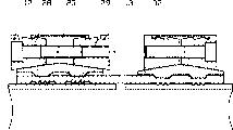
Fig. 1 looks by a vertical profile by assembling pipe joint of the present invention that is made in both sides, its symmetrical center line A-A left side expression one prestressing, symmetrical center line A-A represents on the right side half assembling pipe joint that compresses;
Fig. 2 looks by the vertical profile of the assembling pipe joint of the supporting sleeve of packing into having of Fig. 1;
Fig. 3 looks by the vertical profile of the upper half of the assembling pipe joint of Fig. 1, and wherein mutual aspectant press ring shifts near in opposite directions by screw;
Fig. 4 one surface has the vertical profile of the upper half of the hold-down ring of classification cone structure and looks;
Fig. 5 is divided into two views of the hold-down ring of (fan-shaped) piece by groove;
Fig. 6 looks by the vertical profile of the upper half of the another kind of form of implementation of assembling pipe joint;
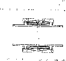
Fig. 7 looks by the vertical profile by the another kind of form of implementation of assembling pipe joint of the present invention that is made in both sides;
Fig. 8 looks by the vertical profile by the assembling pipe joint of Fig. 7, and wherein hold-down ring separates;
Fig. 9 looks by the vertical profile by another kind of form of implementation of the present invention.
Embodiment
Fig. 1 represents to look by a vertical profile by assembling pipe joint 1 of the present invention that is made in both sides, and wherein the half assembling pipe joint 1 of a prestressing is represented in symmetrical center line A-A left side, and symmetrical center line A-A represents on the right side half assembling pipe joint 1 that compresses.
Assembling pipe joint 1 is made up of a hollow cylinder connecting sleeve 2 that has back-to-back axial insertion end 3, and the end of pipeline 4 to be connected inserts in this insertion end.It is symmetrical that assembling pipe joint 1 is done with respect to center line A-A, that is to say, connecting element of narrating below and interactively relate to half of connecting sleeve 2 all the time.In the present embodiment that interconnects two pipelines 4 hermetically with same diameter, the structure of the connecting element on half of connecting sleeve 2 and second half is with respect to center line A-A symmetry.Therefore the structure and the working principle of assembling pipe joint 1 one sides only are described under described situation.
Connecting sleeve 2 is usually by making with the material identical materials of pipeline 4.
Connecting sleeve 2 is hollow cylinders, and its wall thickness on connecting sleeve 2 total lengths remains unchanged basically, and according to (certain) proportionate relationship of pipeline 4 external diameters and its wall thickness.
The inboard of connecting sleeve 2 has radial ringed tooth portion, one of them tooth portion 6 be located at connecting sleeve 2 insertion end 3 near, second tooth portion 7 towards center line A-A direction apart from first tooth portion 6 certain distances.Tooth portion 6,7 is made up of three teeth side by side in described embodiment, and they contract in this wise backward with respect to the internal diameter of connecting sleeve 2, makes the internal diameter that is equal to or greater than connecting sleeve 2 at the diameter of tooth top area inner measuring.Avoid thus when pipeline 4 inserts connecting sleeve 2 inner chambers, tooth top being damaged.
Tooth top according to the different tooth portion 6,7 of use occasion can be done differently.For example it is contemplated that, tooth top is scabbled or rounding, so that the performance that tooth portion 6,7 is clamp-oned in pipeline 4 surfaces exerts an influence thus.
Be provided with position structure on connecting sleeve 2 outsides, they are radial ringed, relative with each tooth portion 6,7 level and smooth grooves 8,9.The effect of these grooves 8,9 explains later on again.
A kind of special application lower joint sleeve 2 in symmetrical center line A-A zone-just be positioned at the zone of link position-do mutually Face to face with a convex shoulder part to inner process at pipeline 4 terminal, it is used for limiting the insertion depth of the pipeline 4 of insertion.Do not narrow down if connecting sleeve 2 is inner resembling in described embodiment, it can be used as the slippage cover so.
On connecting sleeve 2, have one with the pressure-applying unit 10 of its concentric setting, it by hold-down ring 11, two press ring 12,13 and in some cases a covering jacket 14 form.
Hold-down ring 11 is rotational symmetric hollow cylinders, and it has the position structure that is used for fixing on connecting sleeve 2 on the inboard.This position structure is the radial protrusion 15,16 of an annular, and they are done so that the groove 8,9 on they and connecting sleeve 2 outsides matches.Determine the position of hold-down ring 11 on connecting sleeve 2 by each groove 8,9/ projection 15,16 pairings.The diameter of the diameter of bottom land and projection is selected like this, makes to reach a kind of prestressing state of realizing by Spielpassung between two members, and this makes that the assembling of assembling pipe joint 1 is more convenient.
One male cone (strobilus masculinus) 17,18 from hold-down ring 11 ends is arranged on the outer surface of hold-down ring 11, they continuously and plane shape raise towards symmetrical center line B-B.
Each male cone (strobilus masculinus) 17,18 of hold-down ring 11 sets a press ring 12,13.Press ring the 12, the 13rd, rotational symmetric hollow cylinder, they have an inner conical surface 19,20 towards symmetrical center line B-B on the side within it.With the contacted method of conical surface, these inner conical surfaces 19,20 of press ring 12,13 and the affiliated male cone (strobilus masculinus) 17,18 of hold-down ring 11 are matched by two members.
On a plurality of male cone (strobilus masculinus)s 17,18 of prestressing state press ring 12,13 at hold-down ring 11 of assembling pipe joint 1, be advanced to so far away, make and have enough distances between the mutual aspectant press ring 12,13, this distance is determined in this wise, makes to allow press ring 12,13 axial motion in opposite directions when implementing compaction process.
The upside of each press ring 12,13 has a pair of radial ringed groove 21,22 that leaves certain distance mutually, and they are used for installing the covering jacket 14 of supporting element effect together.Covering jacket 14 has seamed edge 24,25 to inner process in its edge, they and circular groove 21,22 tablings.Wherein seamed edge 24,25 and each are chimeric near the groove 21 of symmetrical center line B-B under the prestressing state of assembling pipe joint 1, and at the chimeric groove 22 that is positioned at the next door of transferring to of the impaction state seamed edge 24,25 of assembling pipe joint 1.For make press ring 12,13 in opposite directions during axial motion this transfer easier, no matter be that seamed edge 24,25 or groove 21,22 all have terminal slope.
Covering jacket 14 satisfies the effect that each element of pressure-applying unit 10 is remained on the state that can assemble when assembling pipe joint 1 prestressing.
The effect of covering jacket 14 is when assembling pipe joint 1 compresses, and prevents two press ring, 12,13 unexpected getting loose, and avoids the pollution of the middle cavity 26 between press ring 12,13 in addition.
The following describes the process of setting up seal for pipe joints connection set 1.On connecting sleeve 2, put the pressure-applying unit of forming by a hold-down ring 11, a pair of press ring 12,13 and covering jacket 14 10.At this moment the inwardly outstanding projection 15,16 of hold-down ring 11 snaps in the groove 8,9 that is positioned on connecting sleeve 2 outsides, thereby determines the position of pressure-applying unit 10 on connecting sleeve 2.The assembling place be made and be supplied to these assemblies can in advance according to the nominal bore diameter of pipeline 4 to be connected.End at assembling place pipeline 4 to be connected inserts in the connecting sleeve 2 with the length of regulation.To belong to a pair of press ring 12,13 by means of suitable, well-known therefore not elsewhere specified instrument axially pushes in opposite directions.At this moment press ring 12,13 is slided on the conical surface between press ring 12,13 and the hold-down ring 11, and the material of lateral extrusion clamping element 11.Extruding is at first undertaken by the projection 15,16 of hold-down ring 11, and is delivered to the tooth portion 6,7 that is positioned at groove 8,9 opposites.Tooth portion 6,7 radially clamp-ons in the surface of pipeline 4 of insertion, and guarantees being tightly connected between connecting sleeve 2 and the pipeline 4 in this way.
The axial force that cone angle by press ring 12,13 and hold-down ring 11 and the distance of passing by when axially closing up can apply needs and the annular tooth part 6,7 of connecting sleeve 2 are pressed into the degree of depth and the impacting force of pipeline 4 to be connected and exert one's influence.
Expression and the same assembling pipe joint 1 described in Fig. 1 among Fig. 2, difference is the supporting sleeve 27 of packing in pipeline 4, it provides for pipeline 4 in crush-zone to support tooth portion 6,7 to clamp-on pipeline 4 drag in surperficial.Supporting sleeve 27 has the radial protrusion of annular on its outer surface, and they compensate the error of pipeline when supporting sleeve 27 is packed pipeline 4 into.
Expression applies axial moving force by means of 23 pairs of press ring of screw 12,13 among Fig. 3. Press ring 12,13 has the hole of axial setting on part circumference 32, wherein through hole 28 is made in the hole in press ring 12, and tapped hole 29 is made in the axial relative hole in press ring 13.By twisting screw 23 equably press ring 12,13 is moved in opposite directions on conical surface.
As shown in Figure 4, the upside of hold-down ring 11 is made stepped shaft to symmetrical center line B-B, and section 30 back of making plane shape that wherein a taper raises connect the heavy section 31 of cutting of a band, and it does tapered contraction shape.This order preferably repeats 4 times until symmetrical center line B-B.This heavy section of cutting 31 prevents during with its complementation prestressing or final skidding during impaction state in the structure of press ring 12,13 inboards.
The expression part is made the hold-down ring 11 of sector structure among Fig. 5.The matrix of hold-down ring 11 is slotted till the radial protrusion 15 and 16 of annular.Under the constant situation of the property retention of pressure-applying unit 10 and lateral extrusion, reduce desired axial pressing force thus.The radially shortening of the quantity of groove 34 and width and hold-down ring 11 has direct relation.
Hold-down ring 11 also can be made up of single circular-arc quadrant in a kind of modification structures.
The shape of the positioning area between hold-down ring 11 shown in Fig. 6 and the connecting sleeve 2 can further be revised.For example positioning area can be made on the connecting sleeve 2 circlewise.These circular grooves 33 are as the compensating basin that is positioned at the excessive stress that occurs when compressing the pipeline with big tolerance range in limited time on the tolerance range in the member of connection set in the tolerance of outer diameter tube.
The shape of the bottom surface of the hold-down ring 11 in an embodiment can further be revised, and does not exceed the protection domain of patent therefrom.
In another kind of form of implementation, introduced a kind of assembling pipe joint.Be made up of a hollow cylinder connecting sleeve 102 that has axial back-to-back insertion end 103 by Fig. 7 assembling pipe joint 101, the end of pipeline 104 to be connected inserts in this insertion end, till symmetrical center line C-C.
Connecting sleeve 102 inboards have the radial teeth portion of annular, wherein tooth portion 106 be arranged on connecting sleeve 102 insertion end 103 near, second tooth portion 107 is arranged near the pipe end that inserts from first tooth portion 106 a distance towards center line C-C direction.Therefore the end of pipeline 104 is located in connecting tube 102 in this wise, makes each pipe end not only dispose a tooth portion 106 but also dispose a tooth portion 107.
On connecting sleeve 102, have one with the pressure-applying unit 110 of its concentric setting, it is made up of hold-down ring 111 and two press ring 112,113.
Hold-down ring 111 is rotation symmetry hollow cylinders isometric basically with connecting sleeve 102.Hold-down ring 111 and connecting sleeve 102 have the position structure of axial action on its end, it is rendered as flat annular ledge 121 on connecting sleeve 102, are rendered as the plat slot 122 that matches with lug 121 on hold-down ring 111.These position structures are determined the axial position of hold-down ring 111 on connecting sleeve 102, and guarantee the sealed connection of shape between prestressing state lower joint sleeve and hold-down ring.This combination of the discrete component by assembly reach assembling pipe joint higher can prefabricated degree.
At hold-down ring 111 upsides male cone (strobilus masculinus) 117,118 from hold-down ring 111 ends is arranged, their raise continuously and entirely, until symmetrical center line C-C.
Each male cone (strobilus masculinus) 117,118 of hold-down ring 111 sets a press ring 112,113.Press ring the 112, the 113rd, rotational symmetric hollow cylinder, it has the inner conical surface 119,120 towards symmetrical center line C-C within it on the side.Male cone (strobilus masculinus) 117,118 under these inner conical surfaces 119,120 of press ring 112,113 and the hold-down ring 111 matches, and wherein two members are in contact with one another on conical surface.
Prestressing state at assembling pipe joint 101, press ring 112,113 advances so far away to each male cone (strobilus masculinus) 117,118 of hold-down ring 111, make the enough distances of formation between mutual aspectant press ring 112,113, its size is selected like this, makes to allow press ring 112,113 axial motions in opposite directions when carrying out compaction process.
Set forth the process of the assembling pipe joint 101 of setting up sealing below.On connecting sleeve 102, put a pressure-applying unit of forming by hold-down ring 111 and a pair of press ring 112,113.The assembling place be made and be transported to this assembly can in advance by the nominal bore diameter of pipeline 104 to be connected.End in the assembling place with pipeline 104 to be connected inserts connecting sleeve 102 with the length of a regulation, till symmetrical center line C-C.Belong to a pair of press ring 112,113 by means of suitable, well-known and therefore not elsewhere specified tool spindle to moving in opposite directions.At this moment press ring 112,113 is slided on the conical surface between press ring 112,113 and the hold-down ring 111, and the material of lateral extrusion hold-down ring 111.Extruding is at first undertaken by the projection 115,116 of hold-down ring 111, and is delivered in the tooth portion 106,107 relative with protruding 115,116.Tooth portion 106,107 radially clamp-ons the surface of the pipeline 104 of insertion, and guarantees being tightly connected between connecting sleeve 102 and the pipeline 104 by this way.
The male cone (strobilus masculinus) 117,118 of hold-down ring 111 is also made stepped shaft in this special form of implementation.In other words, from the end of hold-down ring 111, follow the taper constriction of a reduced size one of male cone (strobilus masculinus) bigger regional back.This ladder-type structure repeatedly repeats till symmetrical center line on whole male cone (strobilus masculinus) 117,118.Correspondingly the inner conical surface 119,120 of press ring 112,113 is made complementation.
The function of this hierarchic structure on mutual aspectant surface has the meaning of two aspects.The combination of chimeric each element of assurance assembly that the shape when the prestressing state between hold-down ring 111 and the press ring 112,113 is sealed, thus the high manufacturing in advance of assembling pipe joint guaranteed.Guarantee to avoid press ring slippage from the hold-down ring in the identical structure of impaction state.Thereby improve the reliability that pipeline connects when different loads.
In by the form of implementation of Fig. 8 hold-down ring 111 its radial symmetric center line D-D punish into hold-down ring section 111 ', 111 ".Two hold-down ring sections 111 ' and 111 " interconnect by an axial central ring 140; wherein central ring 140 has with hold-down ring section 111 ' and 111 " identical internal diameter is so that make by hold-down ring section 111 ' and 111 " reach hold-down ring unit same length of mobile phase on connecting sleeve 102 that central ring 140 is formed.
Be positioned at flange 141 ', 141 " between cavity be used for installing unillustrated pressurizing tool, wherein pressurizing tool is bearing on the flange on the one hand, under being bearing on the other hand on the outwardly directed end face of press ring.The advantage of this structure is to shorten the pressurization distance, thereby dwindles pressurizing tool greatly.
By means of another embodiment the present invention is illustrated.Device is used for the wiper seal connection of the aspectant concentric pipe end of two same nominal bore diameters in this embodiment.Be confined to a side of device by the assembling pipe joint 201 of Fig. 9 design, because it does with respect to center line A-A symmetry.
Put a hold-down ring 211 on this section of connecting sleeve 202, the internal diameter of hold-down ring is slightly larger than the external diameter of connecting sleeve 202.Hold-down ring 211 has one from male cone (strobilus masculinus) 217,218 two ends, that raise towards hold-down ring 211 centers on its outside.
Hold-down ring 211 sets a press ring 212,213 with one heart in each side.Each press ring 212,213 side is within it done to such an extent that have inner conical surface 219,220, and they are corresponding to male cone (strobilus masculinus) 217,218.Malcompression position press ring 212,213 at the device of being represented by reference character 245 is enclosed within on each stub area of hold-down ring 211, and at this moment conical surface (217/219,218/220) fits together in this zone mutually.
Press ring 212,213 moves to the compacted position that the usefulness 246 of device is represented in opposite directions from these 245s, position by means of unillustrated instrument on conical surface.At this moment hold-down ring 211 is radially clamp-oned connecting sleeve 202, and this makes tooth 206 radially clamp-on in the surface of pipe end 204 again.The non-removable pipeline that forms sealing in this way connects.
Major character of the present invention is, each element of assembling pipe joint can preassembly as connecting sleeve 202, hold-down ring 211 and press ring 212,213, so that make them offer the assembling place as the assembly of compactness.Each element need design to such an extent that have such structure for this reason, and it makes each element that definite position be arranged mutually.
Make hold-down ring 211 on its outside with similar method, press ring 212,213 designs on the side to such an extent that have and be used for the corresponding construction of location mutually within it.
Hold-down ring 211 designs to such an extent that be with a position structure 237,238 respectively on its male cone (strobilus masculinus) 217,218 near its end, have another position structure 239,240 therein near the heart, and corresponding press ring 212,213 is provided with a position structure 241,242 at its place, end towards hold-down ring 211 on it is made in the inner conical surface 219,220 of its inboard, is provided with another position structure 243,244 in the tail end of hold-down ring 211 dorsad at it.
Different position structures according to assembling pipe joint 201 states are coordinated in a different manner mutually.Be made in position structure 237,238 on the hold-down ring 211 and the position structure 241,242 of press ring 212,213 matches at the malcompression state of assembling pipe joint 201.Make all elements of assembling pipe joint 201 be merged into an element of construction in factory thus, it can offer the assembling place with this compact form.
When compressing, causes assembling pipe joint 201 that chimeric position structure changes in this wise between hold-down ring 211 and the press ring 212,213, make on the one hand the position structure 239 and 240 and the position structure 241,242 of press ring 212,213 of hold-down ring 211, make on the other hand hold-down ring 211 position structure 237 and 238 and the position structure 243,244 of press ring 212,213 establish business relations.Prevent that in this way press ring 212,213 from compressing the back by the cone structure slippage, and damage the durability of assembling pipe joint 201 thus.
Another feature of the present invention is the structure of hold-down ring 211.Hold-down ring 211 is made up of the single sector unit that leaves certain distance mutually in its cross section, and they evenly surround connecting sleeve 202.Hold-down ring 211 is being slotted on its whole wall thickness on its circumference vertically for this reason, and the connecting tendon sheet wherein preferably is set between adjacent sector unit, and they keep the shape of hold-down ring 211.The advantage of this structure is, deformation work when compressing assembling pipe joint 201 between hold-down ring 211 and the press ring 212,213 reduces, because hold-down ring 211 diameters expections and necessary reducing at first by the closed of the groove between the adjacent sector unit rather than the distortion realization by hold-down ring 211.On the section of the receiving pipeline end 204 that the diameter of hold-down ring 211 reduces to be delivered to connecting sleeve 202 by moving in opposite directions of press ring 212,213, wherein tooth 206 is clamp-oned pipe end 204 surfaces, thereby guarantees to obtain the pipe joint 201 of a sealing.
The another kind of possibility that makes each sector unit of hold-down ring 211 leave certain distance mutually is, puts into a partition adjustable pad between sector unit, and it guarantees that sector unit is evenly distributed on hold-down ring 211 circumference.Separation pad when assembling pipe joint compresses between the adjacent sector unit is extruded.
A kind of assembling pipe joint of the invention, it guarantees in the versatility for the treatment of height aspect the connecting tube quality requirement.It has the characteristic that can estimate, even and the pipeline that when big outer diameter tube error, also obtains high-seal connect.
Be reduced to by solution of the present invention press ring is pressed on needed power on hold-down ring and the connecting sleeve.
Its feature is with respect to vibration, axial tension on the pipeline and the high stability of extreme temperature fluctuation.
Assembling pipe joint is made up of easily manufactured, rotational symmetric single part, and they can realize best combination about the performance that assembling pipe joint is pursued aspect the selection of the employed material with its property that depends on function.
Can realize the pressure-applying unit construction standardization by solution of the present invention.
Adopt with a kind of pressure-applying unit structure in conjunction with different connecting sleeve materials or structural type.Therefore also can only in certain limit, compress the pipeline of various outer diameter by the adaptive measure of connecting sleeve configuration aspects.
Although the present invention can find out without difficulty for the personnel that are familiar with specialty by representing that some preferred embodiments of the connection of two pipelines are illustrated, can carry out different corrections and change, and not depart from the protection domain of back claim.For example as can be seen, only adopt by what the present invention made and compress connection, but on the other end, be equipped with common connecting element in a side, screw-type flange connecting apparatus for example, this only is a kind of special application form of the present invention.
Claims (18)
1. set up the assembling pipe joint that is tightly connected with at least one pipe end, form by the rotational symmetric matrix of a sleeve shape, wherein matrix has at least one columniform basically, as to be provided with tooth-shape structure inner chamber that is used for the pipe laying end, tooth-shape structure can radially be clamp-oned in the surface that is installed in the pipe end in the inner chamber by means of the pressurization device that acts on the outer surface of matrix, it is characterized by:
Matrix is made up of the connecting sleeve with first-class substantially wall thickness (2) of a hollow cylinder, wherein leave radial ringed tooth portion (6,7) certain distance, that contract after with respect to connecting sleeve (2) internal diameter mutually being provided with at least two on connecting sleeve (2) inboard, wherein on connecting sleeve (2) outside, form radial ringed, relative with each tooth portion (6,7), its width is equivalent to the position structure (8,9) of tooth portion (6,7) width
Be provided with a hold-down ring (11) that can on connecting sleeve (2), move with one heart, it does to such an extent that almost covering connecting sleeve (2) on the whole length, wherein hold-down ring (11) has projection (15,16) radial ringed, that match with position structure (8,9) within it on the side, and on outside it, have a male cone (strobilus masculinus) (17,18) that raises to its center from hold-down ring (11) two ends
Hold-down ring (11) sets the press ring (12,13) that pericardium together encloses hold-down ring (11) in every side, wherein each press ring (12,13) has an inner conical surface corresponding to male cone (strobilus masculinus) (17,18) (19,20) on the side within it, makes that axially moving to one in opposite directions from an initial position of leaving certain distance in press ring (12,13) radially clamp-ons in the surface of the pipeline of being admitted by connecting sleeve (2) (4) tooth portion (6,7) by projection (15,16) with position structure (8,9) that projection (15,16) matches when almost not having the final position of distance.
2. by the described device of claim 1, it is characterized by: the surface of hold-down ring (11) is made step-like till symmetrical center line (B-B), wherein connect a heavy section of cutting (31) in section (30) back of doing smoothly that a taper raises, the heavy section of cutting is done tapered contraction-like, wherein this order can repeatedly repeat, the inboard of press ring (12,13) do with the respective regions complementation of hold-down ring (11).
3. by the described device of claim 1, it is characterized by: each press ring (12,13) upside is done to such an extent that have an a pair of radial ringed groove (21 that leaves certain distance, 22), so that a cross-over connection press ring (12 to be installed, the cylindrical covering jacket (14) of the middle cavity 13) (26), wherein covering jacket (14) has the seamed edge (24 that inwardly stretches out in its edge, 25), they can with circular groove (21,22) chimeric in this wise, make seamed edge (24,25) chimeric at prestressing state and each groove (21) of assembling pipe joint (1) near symmetrical center line (B-B), and when the impaction state of assembling pipe joint (1) and the groove (22) on its next door chimeric, wherein no matter be seamed edge (24,25) still be groove (21,22) all has terminal slope.
4. by the described device of claim 1, it is characterized by: in projection (15,16), form a radial ringed groove (33), to form a compensating basin.
5. by the described device of claim 1, it is characterized by: press ring (12,13) has the axial bore that is arranged on its common part circumference (32), acts on strain component between the press ring (12,13) with installation.
6. by the described device of claim 5, it is characterized by: these Kong Zaiyi press ring is made through hole (28) on (12,13), makes to be used for the tapped hole (29) of mounting screw (23) on relative press ring (13,12).
7. by the described device of claim 1, it is characterized by: hold-down ring (11) is made up of many sector units.
8. by claim 1 or 7 described devices, it is characterized by: hold-down ring (11) is provided with the groove (34) that does not contact with projection (15,16) zone axial distribution, feasible at upside.
9. by claim 1 or 7 described devices, it is characterized by: putting into the separation pad of guaranteeing that sector unit is symmetrically distributed on hold-down ring (11) circumference between the sector unit.
10. by the described device of claim 1, it is characterized by: the supporting sleeve (27) of in pipeline (4) end, packing into, wherein supporting sleeve (27) has annular radial protrusion on its outside, to compensate pipeline (4) in the big error aspect the nominal diameter, and wherein supporting sleeve (27) has a shaft shoulder in a side, and its limits pack into the degree of depth of pipeline (4) of supporting sleeve (27).
11. set up the device that is tightly connected with at least one pipe end, form by the rotational symmetric matrix of a sleeve shape, wherein matrix has the inner chamber that is used for the pipe laying end of at least one columniform basically outfit tooth-shape structure, tooth-shape structure can radially be clamp-oned the surface that is contained in the pipe end in the inner chamber by means of the pressurization device that acts on the outer surface of matrix, it is characterized by:
Connecting sleeve (102) is done to such an extent that be used for installing two pipe ends (104) that can be inserted into symmetrical center line (C-C),
Be provided with one and can go up the hold-down ring (111) that moves at connecting sleeve (102) with one heart, it does to such an extent that almost cover connecting sleeve (102) on whole length, wherein hold-down ring (111) within it side have projection (115,116) radial ringed, that match with the outer surface of connecting sleeve (102), and on its outside, has the male cone (strobilus masculinus) (117,118) that raises from each end of hold-down ring (111) towards the center
Hold-down ring (111) sets the press ring (112 that pericardium together encloses hold-down ring (111) at each end, 113), each press ring (112 wherein, 113) within it side have one with male cone (strobilus masculinus) (117,118) corresponding inner conical surface (119,120), make in press ring (112,113) from an initial position of leaving certain distance move axially to one when almost not having the final position of distance by projection (115,116) and with the projection (115, the outer surface of the connecting sleeve that 116) matches (102) makes tooth portion (106,107) radially clamp-on in the surface that is installed in the pipeline (104) in the connecting sleeve (102).
12. by the described device of claim 11, it is characterized by: the inner chamber of connecting sleeve (102) is provided with an annular ledge (106) in its insertion end, it is arranged on the opposite of the projection (115) of hold-down ring (111), the inner chamber of connecting sleeve (102) is provided with a pair of annular tooth part (107) at it near in the zone of symmetrical center line (C-C), it is arranged on the opposite of the projection (116) of hold-down ring (111), and wherein each pipe end (104) not only sets a lug (106) but also set a tooth portion (107).
13., it is characterized by: the interior edge chamfering or the rounding of connecting sleeve (102) inlet by claim 11 or 12 described devices.
14. by claim 11 or 12 described devices, it is characterized by: the entry end of connecting sleeve (102) has a flat lug (121) on its cylindrical, it with the terminal inboard of hold-down ring (111) on a plat slot (122) with a kind of can make connecting sleeve (102) and hold-down ring (111) mutually the mode of axially locating cooperate.
15. by the described device of claim 11, it is characterized by: hold-down ring (111) radial symmetric center line (D-D) punish into two sections (111 ', 111 "); they can interconnect by an axial central ring (140); wherein central ring (140) have with the hold-down ring section (111 ', the identical internal diameter of 111 ") so that make by the hold-down ring section (111 ', the hold-down ring unit that forms of 111 ") and central ring (140) connecting sleeve (102) go up mobile phase with length.
16. by the described device of claim 15, it is characterized by: central ring (140) on its outside, do have two separated by a distance, as each hold-down ring section (111 ', the annular flange flange towards the backstop of the end face of symmetrical center line (D-D) 111 ") (141 '; 141 "), in addition wherein central ring (140) have respectively one from flange (141 ', 141 ") outwardly directed zone; it end at the edge that a radially outward stretches out (142 '; 142 "), the hold-down ring section (111 ' 111 ") and edge (142 '; the end that 142 ") match has the diameter zone bigger than internal diameter, processing one groove in this zone (143 ', 143 "), it and edge (142 '; 142 ") tabling.
Set up the device that is tightly connected 17. be used for aspectant with one heart pipe end, form by the rotational symmetric matrix of a sleeve shape, wherein matrix has the inner region of a columniform basically outfit tooth-shape structure respectively, so that each pipe end to be installed, tooth portion can radially clamp-on in the surface in the pipe end that is installed in the inner chamber by means of acting on pressurization device on the outer surface of matrix, it is characterized by:
Matrix is made up of a hollow cylinder connecting sleeve (202) with first-class substantially wall thickness, wherein in each inner region of connecting sleeve (202), be provided with at least two and leave the radial ringed tooth (206) that contracts behind internal diameters certain distance, mutually with respect to connecting tube (202)
Be provided with a pair of hold-down ring (211) that can upward move at connecting sleeve (202) with one heart, they are designed to surround respectively connecting sleeve (202) in the inner region section, each hold-down ring (211) has a male cone (strobilus masculinus) (217,218) that raises towards its center from hold-down ring (211) two ends on its outside
Each hold-down ring (211) sets the press ring (212,213) that pericardium together encloses hold-down ring (211) in every side, wherein each press ring (212,213) has the inner conical surface (219,220) of the male cone (strobilus masculinus) (217,218) corresponding to hold-down ring (211) within it on the side, makes radially to clamp-on in the surface of the pipeline (204) that is contained in the connecting sleeve (202) at press ring (212,213) tooth (206) when the initial position (245) of leaving certain distance axially moves to a final position (246) that does not almost have a distance in opposite directions.
18. by the described device that is used for setting up the closed conduit connection of claim 17, it is characterized by: on connecting sleeve (202) outside, in the inner region section, form radial ringed position structure (235) respectively, especially do grooving, hold-down ring (211) has radially on the side within it, match with position structure (235), especially make the circular orientation structure (236) of lug, wherein position structure (235,236) play a part to make connecting sleeve (202) and hold-down ring (211) to be fixed into an element of construction in pre-assembled state (245), hold-down ring (211) is at its male cone (strobilus masculinus) (217,218) upward near an one end, has a position structure (237,238), has another position structure (239 therein near the heart, 240), and corresponding press ring (212,213) at its inner conical surface (219 that forms in the inboard, 220) upward one position structure (241 is arranged in its tail end towards hold-down ring (211), 242), another position structure (243 is arranged the tail end of hold-down ring (211) dorsad at it, 244), it matches in this wise with the position structure of going up formation at hold-down ring (211), make and make position structure (237/241 in order to obtain a element of construction in pre-assembled state (245), 238/242) chimeric mutually, with make position structure (237/243 for the device (246) that obtains compressing, 239/241,240/242,238/244) chimeric mutually.
Applications Claiming Priority (4)
| Application Number | Priority Date | Filing Date | Title |
|---|---|---|---|
| DE19958102A DE19958102C1 (en) | 1999-12-02 | 1999-12-02 | Pressure-sealed coupling for pipes has a coupling sleeve with inner teeth covered by a pressure ring and end press rings which force the teeth by inner projections against the pipe surface with min pressure |
| DE19958102.9 | 1999-12-02 | ||
| DE10016312A DE10016312A1 (en) | 1999-12-02 | 2000-03-31 | Device for producing a pipe coupling |
| DE10016312.2 | 2000-03-31 |
Publications (2)
| Publication Number | Publication Date |
|---|---|
| CN1402824A CN1402824A (en) | 2003-03-12 |
| CN1190613C true CN1190613C (en) | 2005-02-23 |
Family
ID=26005146
Family Applications (1)
| Application Number | Title | Priority Date | Filing Date |
|---|---|---|---|
| CNB008165076A Expired - Fee Related CN1190613C (en) | 1999-12-02 | 2000-11-16 | Device for producing pipe coupling |
Country Status (19)
| Country | Link |
|---|---|
| US (1) | US6769722B1 (en) |
| EP (1) | EP1234136B1 (en) |
| JP (1) | JP4700878B2 (en) |
| KR (1) | KR100668094B1 (en) |
| CN (1) | CN1190613C (en) |
| AT (1) | ATE256836T1 (en) |
| AU (1) | AU777857B2 (en) |
| CA (1) | CA2393957A1 (en) |
| CZ (1) | CZ298241B6 (en) |
| DE (2) | DE10016312A1 (en) |
| DK (1) | DK1234136T3 (en) |
| ES (1) | ES2213067T3 (en) |
| HU (1) | HU224517B1 (en) |
| NO (1) | NO335311B1 (en) |
| PL (1) | PL192174B1 (en) |
| PT (1) | PT1234136E (en) |
| RU (1) | RU2258169C2 (en) |
| TR (1) | TR200400464T4 (en) |
| WO (1) | WO2001040696A1 (en) |
Families Citing this family (29)
| Publication number | Priority date | Publication date | Assignee | Title |
|---|---|---|---|---|
| US7272204B2 (en) * | 2004-08-31 | 2007-09-18 | General Electric Company | Method and apparatus for clamping a riser brace assembly in nuclear reactor |
| GB2462016B (en) * | 2005-02-25 | 2010-06-30 | Parker Hannifin Plc | A coupling |
| US20080213709A1 (en) * | 2005-11-18 | 2008-09-04 | Russell Clayton | Gas supply coupling for a water heater |
| US20090302603A1 (en) * | 2005-11-18 | 2009-12-10 | Russell Clayton | Gas supply coupling for a water heater |
| KR100771451B1 (en) * | 2006-07-12 | 2007-10-30 | 주식회사 한국번디 | Pipe coupling machine |
| SG175643A1 (en) * | 2006-10-17 | 2011-11-28 | Car Ber Investments Inc | Pipe fitting and pipe coupling assembly employing such fitting |
| US8335292B2 (en) * | 2006-10-19 | 2012-12-18 | General Electric Company | Jet pump diffuser weld repair device and method |
| PL2162662T3 (en) * | 2007-06-18 | 2012-09-28 | Weidmann Ltd | Connecting arrangement for a pipe union |
| PL2158425T3 (en) * | 2007-06-18 | 2011-06-30 | Weidmann Ltd | Connecting arrangement for a pipe union |
| DE602008004428D1 (en) * | 2008-02-19 | 2011-02-24 | Continental Automotive Gmbh | coupling device |
| EP2221520B1 (en) * | 2009-02-18 | 2013-10-23 | Parker-Hannifin Corporation | Hose fitting |
| DE102009015186A1 (en) * | 2009-03-31 | 2010-10-14 | Viega Gmbh & Co. Kg | Fitting for connection of a pipe |
| CN101625054B (en) * | 2009-08-20 | 2012-10-03 | 中舟海洋科技(上海)有限公司 | Radial extrusion type joint |
| US8245789B2 (en) * | 2010-06-23 | 2012-08-21 | Halliburton Energy Service, Inc. | Apparatus and method for fluidically coupling tubular sections and tubular system formed thereby |
| DE102012105655A1 (en) * | 2012-06-28 | 2014-01-02 | Viega Gmbh & Co. Kg | Press jaw and method for producing a permanent pipe connection and system of a pressing jaw and a fitting |
| KR101386408B1 (en) * | 2012-12-26 | 2014-04-21 | 재단법인 포항산업과학연구원 | Pipe connector |
| CA2897916A1 (en) * | 2013-01-11 | 2014-07-17 | Cerro Flow Products Llc | Fitting for joining tubes and method of joining tubes |
| CN103567297A (en) * | 2013-11-11 | 2014-02-12 | 任少琳 | Connecting die of metal round tubes |
| GB2527109A (en) * | 2014-06-12 | 2015-12-16 | Meta Downhole Ltd | Pipe coupling |
| USD1009227S1 (en) | 2016-08-05 | 2023-12-26 | Rls Llc | Crimp fitting for joining tubing |
| USD994091S1 (en) | 2016-08-05 | 2023-08-01 | Rls Llc | Crimp fitting for joining tubing |
| CN107588255A (en) * | 2017-09-29 | 2018-01-16 | 中国地质大学(武汉) | A kind of oil field ground line connection device |
| CN108331988B (en) * | 2018-04-03 | 2024-03-08 | 亳州职业技术学院 | Building drainage pipeline and efficient sealing connection device and method thereof |
| CN108571630A (en) * | 2018-07-09 | 2018-09-25 | 安徽恒生科技发展集团有限公司 | A kind of run-resistant assembling pipe joint |
| RU2731006C1 (en) * | 2019-10-28 | 2020-08-28 | Общество с ограниченной ответственностью "ВОРМХОЛС Внедрение" | Fastening elements on pipe |
| CN111550624B (en) * | 2020-05-18 | 2021-12-28 | 山东爱客多热能科技有限公司 | Calandria connecting device for district heating system |
| CN111609230B (en) * | 2020-05-22 | 2021-07-20 | 福建得乾集团有限责任公司 | Steel-plastic pipe joint connecting structure and construction method |
| KR102419174B1 (en) * | 2020-12-17 | 2022-07-07 | 김성태 | Pipe Connector |
| CN113635258A (en) * | 2021-08-15 | 2021-11-12 | 江西铜业集团(贵溪)防腐工程有限公司 | Electric melting pipeline press-fitting process, press-fitting tool and press-fitting tool manufacturing process |
Family Cites Families (29)
| Publication number | Priority date | Publication date | Assignee | Title |
|---|---|---|---|---|
| US1281498A (en) * | 1917-04-07 | 1918-10-15 | Peter M Brevig | Pipe-union. |
| DE350608C (en) * | 1919-07-27 | 1922-03-23 | Mannesmann Ag | Pipe connection with wedge-shaped press pieces |
| US2507261A (en) * | 1946-03-06 | 1950-05-09 | Mercier Jean | Coupling |
| US2613959A (en) * | 1948-12-03 | 1952-10-14 | Brockway Company | Coupling for threadless pipes |
| US3474519A (en) * | 1966-11-08 | 1969-10-28 | Boeing Co | Method of making a tube fitting |
| US3477750A (en) * | 1967-10-30 | 1969-11-11 | Jonathan S Powell | Pipe coupling and means and method of assembly |
| US3498648A (en) * | 1968-08-22 | 1970-03-03 | Boeing Co | High temperature and pressure tube fitting |
| US3827727A (en) * | 1969-11-14 | 1974-08-06 | K Moebius | Constrictor ring and tube joint |
| US3765708A (en) * | 1971-11-08 | 1973-10-16 | Boeing Co | Tubing union |
| US4026006A (en) | 1972-06-26 | 1977-05-31 | Moebius Kurt Otto | Method of forming a tube joint |
| US3843167A (en) * | 1973-01-31 | 1974-10-22 | B Gronstedt | Hydraulically actuated pipe coupling |
| US3893720A (en) * | 1973-02-09 | 1975-07-08 | Moebius Kurt Otto | Constrictor ring joint |
| JPS5647437B2 (en) * | 1974-08-26 | 1981-11-10 | ||
| US4482174A (en) * | 1980-09-15 | 1984-11-13 | Lokring | Apparatus and method for making a tube connection |
| US4466640A (en) * | 1981-08-05 | 1984-08-21 | Dresser Industries, Inc. | Pullout resistant pipe coupling |
| US4621844A (en) * | 1982-01-25 | 1986-11-11 | Shell Oil Company | Memory metal connector |
| IL72279A (en) * | 1983-07-19 | 1988-11-30 | Pfister Juerg | Pipe coupling device |
| US4575129A (en) * | 1984-06-15 | 1986-03-11 | O'donnell & Associates, Inc. | Pipelock |
| JPS62220793A (en) * | 1986-03-19 | 1987-09-28 | 大同特殊鋼株式会社 | Pipe body joint |
| JPH03186683A (en) * | 1989-12-14 | 1991-08-14 | Sekisui Chem Co Ltd | Pipe joint |
| DE4002494A1 (en) * | 1990-01-29 | 1991-08-08 | Airbus Gmbh | PIPE FITTING |
| US5088771A (en) * | 1990-02-06 | 1992-02-18 | Sierracin Corporation | Tube union |
| US5110163A (en) * | 1990-03-22 | 1992-05-05 | Lokring Corporation | Pipe fitting with improved coupling body |
| US5452921A (en) * | 1991-10-31 | 1995-09-26 | The Deutsch Company | Axially swaged fitting |
| JPH0673596U (en) * | 1993-03-26 | 1994-10-18 | 住友金属工業株式会社 | Movable pipe end anticorrosion core |
| US5405176A (en) * | 1994-02-15 | 1995-04-11 | Mcdonnell Douglas Corporation | High pressure mechanical seal |
| US5823579A (en) * | 1997-05-21 | 1998-10-20 | Tube-Mac Industries, Ltd. | Device for coupling a flared metal pipe |
| JP3904698B2 (en) * | 1997-10-27 | 2007-04-11 | コスモ工機株式会社 | Tube fixing device |
| US6450553B1 (en) * | 1999-11-05 | 2002-09-17 | Mechl Llc | Axial swage fitting for large bore pipes and tubes |
-
2000
- 2000-03-31 DE DE10016312A patent/DE10016312A1/en not_active Withdrawn
- 2000-11-16 CN CNB008165076A patent/CN1190613C/en not_active Expired - Fee Related
- 2000-11-16 US US10/149,098 patent/US6769722B1/en not_active Expired - Lifetime
- 2000-11-16 CA CA002393957A patent/CA2393957A1/en not_active Abandoned
- 2000-11-16 PL PL364793A patent/PL192174B1/en unknown
- 2000-11-16 DE DE50004823T patent/DE50004823D1/en not_active Expired - Lifetime
- 2000-11-16 EP EP00988706A patent/EP1234136B1/en not_active Expired - Lifetime
- 2000-11-16 HU HU0203346A patent/HU224517B1/en not_active IP Right Cessation
- 2000-11-16 DK DK00988706T patent/DK1234136T3/en active
- 2000-11-16 TR TR2004/00464T patent/TR200400464T4/en unknown
- 2000-11-16 ES ES00988706T patent/ES2213067T3/en not_active Expired - Lifetime
- 2000-11-16 WO PCT/EP2000/011323 patent/WO2001040696A1/en active IP Right Grant
- 2000-11-16 JP JP2001542127A patent/JP4700878B2/en not_active Expired - Fee Related
- 2000-11-16 PT PT00988706T patent/PT1234136E/en unknown
- 2000-11-16 KR KR1020027007047A patent/KR100668094B1/en not_active IP Right Cessation
- 2000-11-16 AT AT00988706T patent/ATE256836T1/en active
- 2000-11-16 AU AU25058/01A patent/AU777857B2/en not_active Ceased
- 2000-11-16 CZ CZ20021646A patent/CZ298241B6/en not_active IP Right Cessation
- 2000-11-16 RU RU2002117439/06A patent/RU2258169C2/en not_active IP Right Cessation
-
2002
- 2002-05-30 NO NO20022572A patent/NO335311B1/en not_active IP Right Cessation
Also Published As
| Publication number | Publication date |
|---|---|
| EP1234136A1 (en) | 2002-08-28 |
| AU777857B2 (en) | 2004-11-04 |
| US6769722B1 (en) | 2004-08-03 |
| CZ20021646A3 (en) | 2002-09-11 |
| AU2505801A (en) | 2001-06-12 |
| DK1234136T3 (en) | 2004-04-05 |
| NO20022572L (en) | 2002-07-24 |
| EP1234136B1 (en) | 2003-12-17 |
| ATE256836T1 (en) | 2004-01-15 |
| NO20022572D0 (en) | 2002-05-30 |
| CA2393957A1 (en) | 2001-06-07 |
| PL364793A1 (en) | 2004-12-13 |
| RU2002117439A (en) | 2004-02-10 |
| DE10016312A1 (en) | 2001-10-04 |
| WO2001040696A1 (en) | 2001-06-07 |
| RU2258169C2 (en) | 2005-08-10 |
| PL192174B1 (en) | 2006-09-29 |
| TR200400464T4 (en) | 2004-04-21 |
| DE50004823D1 (en) | 2004-01-29 |
| KR100668094B1 (en) | 2007-01-11 |
| JP4700878B2 (en) | 2011-06-15 |
| JP2003515706A (en) | 2003-05-07 |
| CN1402824A (en) | 2003-03-12 |
| KR20020079746A (en) | 2002-10-19 |
| NO335311B1 (en) | 2014-11-10 |
| CZ298241B6 (en) | 2007-08-01 |
| HU224517B1 (en) | 2005-10-28 |
| HUP0203346A2 (en) | 2003-01-28 |
| PT1234136E (en) | 2004-05-31 |
| ES2213067T3 (en) | 2004-08-16 |
Similar Documents
| Publication | Publication Date | Title |
|---|---|---|
| CN1190613C (en) | Device for producing pipe coupling | |
| CN1021667C (en) | Seal spacer, join sleeve and seal joint | |
| CN1308607C (en) | Tubular threaded joint which is impervious to the external environment | |
| CN1024215C (en) | Gasket with annular anchoring heel | |
| CN1309986C (en) | Threaded tube joint | |
| CN1813150A (en) | Gasket for pipe coupling and pipe coupling incorporating same | |
| CN1199021C (en) | Ferrule with relief to reduce galling due to wearing | |
| CN1511361A (en) | Electrical terminal socket assembly for vehicular component | |
| CN1485559A (en) | Sealing ring | |
| CN1015326B (en) | Pipe joint element | |
| CN1707298A (en) | Method for making a termination of an optical fibre bundle and corresponding press tool | |
| JPS61171987A (en) | Threaded joint | |
| US20100284843A1 (en) | Stator for an eccentric screw pump or an eccentric screw motor and method of producing a stator | |
| CN1707135A (en) | Method and apparatus for making a cylindrical bearing member | |
| CN1114782C (en) | Housing type pipe coupling | |
| CN103201515A (en) | Axial piston machine | |
| CN1192924C (en) | Wiper bearing for a wiper device of a vehicle and method for mounting a wiper bearing | |
| CN1037385A (en) | Pipe clamping joint | |
| CN1088806C (en) | Screw-on pressure medium-actuated working cylinder with closure components for coupling the cylinder tube | |
| CN1530562A (en) | Connecting flange system for quill shaft | |
| CN101999048A (en) | Coupling having a high torsional flexibility and method for producing the same | |
| CN1813151A (en) | Rotating passage | |
| US5957505A (en) | Branch pipe connection | |
| MXPA97002917A (en) | Coupling member comprising lainclinac | |
| CN1294375C (en) | Coupling |
Legal Events
| Date | Code | Title | Description |
|---|---|---|---|
| C06 | Publication | ||
| PB01 | Publication | ||
| C14 | Grant of patent or utility model | ||
| GR01 | Patent grant | ||
| CF01 | Termination of patent right due to non-payment of annual fee |
Granted publication date: 20050223 Termination date: 20161116 |
|
| CF01 | Termination of patent right due to non-payment of annual fee |