CN1184503C - Video image viewing device and method - Google Patents
Video image viewing device and method Download PDFInfo
- Publication number
- CN1184503C CN1184503C CN98109836.3A CN98109836A CN1184503C CN 1184503 C CN1184503 C CN 1184503C CN 98109836 A CN98109836 A CN 98109836A CN 1184503 C CN1184503 C CN 1184503C
- Authority
- CN
- China
- Prior art keywords
- light
- plate
- image display
- refractive index
- display device
- Prior art date
- Legal status (The legal status is an assumption and is not a legal conclusion. Google has not performed a legal analysis and makes no representation as to the accuracy of the status listed.)
- Expired - Lifetime
Links
Images


Classifications
-
- G—PHYSICS
- G09—EDUCATION; CRYPTOGRAPHY; DISPLAY; ADVERTISING; SEALS
- G09F—DISPLAYING; ADVERTISING; SIGNS; LABELS OR NAME-PLATES; SEALS
- G09F19/00—Advertising or display means not otherwise provided for
- G09F19/12—Advertising or display means not otherwise provided for using special optical effects
- G09F19/20—Advertising or display means not otherwise provided for using special optical effects with colour-mixing effects
-
- G—PHYSICS
- G02—OPTICS
- G02B—OPTICAL ELEMENTS, SYSTEMS OR APPARATUS
- G02B27/00—Optical systems or apparatus not provided for by any of the groups G02B1/00 - G02B26/00, G02B30/00
- G02B27/01—Head-up displays
- G02B27/017—Head mounted
-
- G—PHYSICS
- G02—OPTICS
- G02B—OPTICAL ELEMENTS, SYSTEMS OR APPARATUS
- G02B27/00—Optical systems or apparatus not provided for by any of the groups G02B1/00 - G02B26/00, G02B30/00
- G02B27/01—Head-up displays
- G02B27/017—Head mounted
- G02B27/0172—Head mounted characterised by optical features
-
- G—PHYSICS
- G02—OPTICS
- G02F—OPTICAL DEVICES OR ARRANGEMENTS FOR THE CONTROL OF LIGHT BY MODIFICATION OF THE OPTICAL PROPERTIES OF THE MEDIA OF THE ELEMENTS INVOLVED THEREIN; NON-LINEAR OPTICS; FREQUENCY-CHANGING OF LIGHT; OPTICAL LOGIC ELEMENTS; OPTICAL ANALOGUE/DIGITAL CONVERTERS
- G02F1/00—Devices or arrangements for the control of the intensity, colour, phase, polarisation or direction of light arriving from an independent light source, e.g. switching, gating or modulating; Non-linear optics
- G02F1/01—Devices or arrangements for the control of the intensity, colour, phase, polarisation or direction of light arriving from an independent light source, e.g. switching, gating or modulating; Non-linear optics for the control of the intensity, phase, polarisation or colour
- G02F1/011—Devices or arrangements for the control of the intensity, colour, phase, polarisation or direction of light arriving from an independent light source, e.g. switching, gating or modulating; Non-linear optics for the control of the intensity, phase, polarisation or colour in optical waveguides, not otherwise provided for in this subclass
-
- G—PHYSICS
- G02—OPTICS
- G02B—OPTICAL ELEMENTS, SYSTEMS OR APPARATUS
- G02B27/00—Optical systems or apparatus not provided for by any of the groups G02B1/00 - G02B26/00, G02B30/00
- G02B27/01—Head-up displays
- G02B27/0101—Head-up displays characterised by optical features
- G02B2027/011—Head-up displays characterised by optical features comprising device for correcting geometrical aberrations, distortion
-
- G—PHYSICS
- G02—OPTICS
- G02B—OPTICAL ELEMENTS, SYSTEMS OR APPARATUS
- G02B27/00—Optical systems or apparatus not provided for by any of the groups G02B1/00 - G02B26/00, G02B30/00
- G02B27/01—Head-up displays
- G02B27/0101—Head-up displays characterised by optical features
- G02B2027/0132—Head-up displays characterised by optical features comprising binocular systems
-
- G—PHYSICS
- G02—OPTICS
- G02B—OPTICAL ELEMENTS, SYSTEMS OR APPARATUS
- G02B27/00—Optical systems or apparatus not provided for by any of the groups G02B1/00 - G02B26/00, G02B30/00
- G02B27/01—Head-up displays
- G02B27/017—Head mounted
- G02B2027/0178—Eyeglass type
-
- G—PHYSICS
- G02—OPTICS
- G02B—OPTICAL ELEMENTS, SYSTEMS OR APPARATUS
- G02B5/00—Optical elements other than lenses
- G02B5/30—Polarising elements
-
- G—PHYSICS
- G02—OPTICS
- G02F—OPTICAL DEVICES OR ARRANGEMENTS FOR THE CONTROL OF LIGHT BY MODIFICATION OF THE OPTICAL PROPERTIES OF THE MEDIA OF THE ELEMENTS INVOLVED THEREIN; NON-LINEAR OPTICS; FREQUENCY-CHANGING OF LIGHT; OPTICAL LOGIC ELEMENTS; OPTICAL ANALOGUE/DIGITAL CONVERTERS
- G02F1/00—Devices or arrangements for the control of the intensity, colour, phase, polarisation or direction of light arriving from an independent light source, e.g. switching, gating or modulating; Non-linear optics
- G02F1/01—Devices or arrangements for the control of the intensity, colour, phase, polarisation or direction of light arriving from an independent light source, e.g. switching, gating or modulating; Non-linear optics for the control of the intensity, phase, polarisation or colour
- G02F1/13—Devices or arrangements for the control of the intensity, colour, phase, polarisation or direction of light arriving from an independent light source, e.g. switching, gating or modulating; Non-linear optics for the control of the intensity, phase, polarisation or colour based on liquid crystals, e.g. single liquid crystal display cells
- G02F1/133—Constructional arrangements; Operation of liquid crystal cells; Circuit arrangements
- G02F1/1333—Constructional arrangements; Manufacturing methods
- G02F1/1335—Structural association of cells with optical devices, e.g. polarisers or reflectors
- G02F1/1336—Illuminating devices
- G02F1/133615—Edge-illuminating devices, i.e. illuminating from the side
Landscapes
- Physics & Mathematics (AREA)
- General Physics & Mathematics (AREA)
- Optics & Photonics (AREA)
- Nonlinear Science (AREA)
- Theoretical Computer Science (AREA)
- Engineering & Computer Science (AREA)
- Business, Economics & Management (AREA)
- Marketing (AREA)
- Accounting & Taxation (AREA)
- Liquid Crystal (AREA)
- Transforming Electric Information Into Light Information (AREA)
- Video Image Reproduction Devices For Color Tv Systems (AREA)
- Testing, Inspecting, Measuring Of Stereoscopic Televisions And Televisions (AREA)
- Control Of Indicators Other Than Cathode Ray Tubes (AREA)
- Devices For Indicating Variable Information By Combining Individual Elements (AREA)
Abstract
一种视频图象观看器包括其间有液晶层的第一和第二玻璃板。在第一玻璃板的一个边缘附近有着直线延伸的多个激光二极管选择地发光,其光强度对应于在多个视频行的每个期间视频信号的振幅。光经过全内反射传播穿过第一玻璃板,只在液晶的折射率选择地被改变的区域进入液晶层,折射率的改变通过选择地通电水平带状电极来实现。电极依次被通电以阻止全内反射,使光在对应于视频行的位置穿过液晶层传输进入第二玻璃板。一个或多个全息光学元件把进入的光衍射到预定方向,形成对单个通电电极对和通电激光二极管的每种组合唯一的虚象点位置。
A video image viewer includes first and second glass plates with a liquid crystal layer therebetween. A plurality of laser diodes extending linearly near one edge of the first glass plate selectively emit light with an intensity corresponding to the amplitude of the video signal during each of the plurality of video lines. Light propagates through the first glass plate by total internal reflection and enters the liquid crystal layer only in regions where the refractive index of the liquid crystal is selectively changed by selectively energizing the horizontal strip electrodes. The electrodes are in turn energized to prevent total internal reflection, allowing light to be transmitted through the liquid crystal layer into the second glass plate at positions corresponding to the video lines. One or more holographic optical elements diffract incoming light into predetermined directions to form virtual image point locations unique to each combination of a single energized electrode pair and energized laser diode.
Description
技术领域technical field
本发明涉及视频图象观看器(装置),特别涉及能适用于包括虚拟现实显示(virtual reality viewing)镜和视频监视器的各种应用的小型和轻型的视频观看器。The present invention relates to a video image viewer (device), and more particularly to a small and lightweight video viewer suitable for various applications including virtual reality viewing mirrors and video monitors.
背景技术Background technique
视频观看器件通常广泛用于各种应用。阴极射线管(“CRT”)显示器长期以来用于电视显示,特别是近来作为计算机监视器。用于显示视频图象的更小型器件,例如液晶显示(“LCD”)屏,已经作为CRT显示器的代替品发展起来。Video viewing devices are generally used in a wide variety of applications. Cathode ray tube ("CRT") displays have long been used for television displays and more recently as computer monitors. Smaller devices for displaying video images, such as liquid crystal display ("LCD") screens, have been developed as an alternative to CRT displays.
最近,引入了小型、轻型头戴显示器作为用于“虚拟现实”系统的显示器件,通过为每只眼睛提供分离观看器件并适当改变通过每个器件的可视图象,就可以显示出高分辨率立体平面视频图象。Recently, small, lightweight head-mounted displays have been introduced as display devices for "virtual reality" systems, which can display high-resolution Rate stereoscopic video images.
视频图象观看器件的另一类型是“平视显示器(heads up displays)”(“HUD”),它能使喷气式战斗机飞行员随意处理飞机周围的空间和飞机的条件和特性的大量信息。这就发展为HUD’S被装入飞机的透明座舱罩里面,以及“头部安装显示器”和“头盔显示器”中。Another type of video image viewing device is "heads up displays" ("HUD"), which enable jet fighter pilots to manipulate at their disposal a wealth of information about the space around the aircraft and the conditions and characteristics of the aircraft. This has led to the development of HUD'S being incorporated into the transparent canopy of the aircraft, as well as "head-mounted displays" and "helmet-mounted displays".
所有上述HUD’S都需要从源显示器(例如液晶电视屏)发出光并穿过空气传输一段距离到达反射、折射或衍射表面,该表面将使光改变方向以形成源显示器的虚象。在这种显示器中,全息光学元件一般用作衍射表面,并且一般是高度颜色选择的。但是,仍然希望通过直接产生三维虚象而不需要光从源显示器穿过空气传输来显示视频图象,特别是三维图象。如果能发现不需要使光穿过空气传输实际距离的技术,那么观看器件就能大大缩小,并且甚至可以仿造普通的一副眼镜。这种观看器件的小型、轻型和不引人注目的特征将开辟许多新的应用,例如可以用于袖珍计算机的监视器、高级虚拟现实显示器件,或者作为对聋哑人显示从声音获得的提示信号的代用品。All of the aforementioned HUD'S require light to be emitted from a source display (such as an LCD TV screen) and travel some distance through the air to a reflective, refractive, or diffractive surface that will redirect the light to form a virtual image of the source display. In such displays, holographic optical elements are typically used as diffractive surfaces and are typically highly color selective. However, it remains desirable to display video images, especially three-dimensional images, by directly creating a three-dimensional virtual image without the need for light to travel through the air from a source display. If a technique can be found that doesn't require light to travel an actual distance through the air, viewing devices could be greatly reduced and even mimic an ordinary pair of eyeglasses. The small, lightweight and unobtrusive nature of this viewing device will open up many new applications, such as monitors that can be used in pocket computers, advanced virtual reality display devices, or as a display of audio-derived cues to the deaf Substitutes for signals.
发明内容Contents of the invention
本发明的目的是提供一种适用于显示虚拟图像而无需使光穿过空气传输实际距离的图象显示装置和图象显示系统。SUMMARY OF THE INVENTION It is an object of the present invention to provide an image display device and an image display system suitable for displaying virtual images without requiring light to travel an actual distance through air.
根据本发明,提供一种图象显示装置,包括:由透明材料构成并且有第一折射率的第一板;沿着第一板的表面在多个相应位置上把光束选择性地导入第一板的光发生器,其方式是,使光束按在第一板中全内反射沿着第一板传播的方式,将该光束导入第一板;毗邻第一板设置的折射率调制器,该折射率调制器在第一方向上在彼此分开的各个区域上具有多个调制元件,其中第一方向是光穿过第一板传播的方向,每个调制元件根据对应的控制信号选择性地控制到第一折射率状态,或第二折射率状态,第一折射率状态,使调制元件具有足以低于第一板折射率的折射率,从而使光束在调制元件的区域内保持在第一板中的内部反射,而第二折射率状态,使调制元件具有足以高于第一板折射率的折射率,从而使光束在调制元件区域中射出第一板;毗邻折射率调制器设置的第二光学透明板,该折射率调制器设置在第一和第二板之间;毗邻折射率调制器设置的光学元件,该光学元件用于控制在调制元件区域中射出第一板的光的偏转角;和接收视频信号的视频控制电路,该视频信号具有对应于在多个视频行中每行视频图象的强度调制的振幅,视频控制电路根据每行的视频信号的振幅控制光束的强度,视频控制电路还产生控制信号,以使每个调制元件根据相应的视频信号行被依次转换到它的第二折射率状态。According to the present invention, an image display device is provided, comprising: a first plate made of a transparent material and having a first refractive index; light beams are selectively guided into the first plate at a plurality of corresponding positions along the surface of the first plate; a light generator of the plate in such a way that the light beam is directed into the first plate in such a way that it propagates along the first plate by total internal reflection in the first plate; a refractive index modulator arranged adjacent to the first plate, the The refractive index modulator has a plurality of modulating elements on respective regions separated from each other in a first direction, wherein the first direction is the direction in which light propagates through the first plate, each modulating element is selectively controlled according to a corresponding control signal to a first index of refraction state, or a second index of refraction state, the first index of refraction state, such that the modulating element has a refractive index sufficiently lower than the index of refraction of the first plate such that the light beam remains within the first plate in the region of the modulating element internal reflection in , while the second index state causes the modulating element to have a refractive index sufficiently higher than that of the first plate so that the light beam exits the first plate in the region of the modulating element; an optically transparent plate, the index modulator disposed between the first and second plates; an optical element disposed adjacent to the index modulator for controlling the deflection angle of light exiting the first plate in the region of the modulating element and a video control circuit receiving a video signal having an amplitude corresponding to the intensity modulation of each row of video images in a plurality of video rows, the video control circuit controlling the intensity of the light beam according to the amplitude of the video signal of each row, the video The control circuit also generates control signals to cause each modulating element to be sequentially switched to its second refractive index state in accordance with the corresponding video signal line.
根据本发明,还提供一种图象显示系统,包括:图象显示装置和电子系统,其中图象显示装置包括:由透明材料构成并具有第一折射率的第一板;在沿着第一板的表面的多个相应位置上把光束选择性地导入第一板的光发生器,以使光束按在第一板中按在全内反射沿着第一板传播的方式,将是光束导入第一板中;毗邻第一板设置的折射率调制器,该折射率调制器在第一方向上在彼此分开的各个区域上具有多个调制元件,其中第一方向是光穿过第一板传播的方向,每个调制元件根据相应的控制信号选择地控制到第一折射率状态或第二折射率状态,第一折射率状态,使调制元件具有足以低于第一板折射率的折射率,以使光束在调制元件区域内保持在第一板中的内部反射,而第二折射率状态,使调制元件具有高于第一板折射率的折射率,以容许光束在调制元件的区域射出第一板;毗邻折射率调制器设置的第二光学透明板,折射率调制器设置在第一和第二板之间;和毗邻折射率调制器设置的光学元件,该光学元件用于控制在调制元件的区域中射出第一板的光在第一方向的发散角;电子系统按照在每个视频图象帧中具有多个视频行的视频信号给光发生器和折射率调制器提供信号,该电子系统包括:与光发生器耦合的光控制电路,该控制电路使光发生器在各个位置产生的光强度对应于在每个视频行中的对应点的视频信号的振幅;和与折射率调制器耦合的折射率调制器控制电路,该折射率调制器控制电路对折射率调制器施加控制信号,从而根据在视频信号的每个视频图象帧中的对应视频行选择地使每个调制元件处于第二折射率状态。According to the present invention, there is also provided an image display system, including: an image display device and an electronic system, wherein the image display device includes: a first plate made of a transparent material and having a first refractive index; The light beam is selectively introduced into the light generator of the first plate at a plurality of corresponding positions on the surface of the plate, so that the light beam will be introduced into In the first plate; a refractive index modulator disposed adjacent to the first plate, the refractive index modulator having a plurality of modulating elements on respective regions separated from each other in a first direction, wherein the first direction is light passing through the first plate The direction of propagation, each modulating element is selectively controlled to a first refractive index state or a second refractive index state according to a corresponding control signal, the first refractive index state causing the modulating element to have a refractive index sufficiently lower than the first plate refractive index , so that the beam remains internally reflected in the first plate in the area of the modulating element, and the second index state, the modulating element has a refractive index higher than that of the first plate to allow the beam to exit in the area of the modulating element a first plate; a second optically transparent plate disposed adjacent to the index modulator, the index modulator disposed between the first and second plates; and an optical element disposed adjacent to the index modulator for controlling the modulating the divergence angle of the light exiting the first plate in the first direction in the region of the modulation element; the electronic system provides signals to the light generator and the refractive index modulator according to a video signal having a plurality of video lines in each video image frame, The electronic system includes: a light control circuit coupled to the light generator, which causes the light generator to produce light intensities at various locations corresponding to the amplitude of the video signal at corresponding points in each video line; and the modulator is coupled to a refractive index modulator control circuit that applies a control signal to the refractive index modulator to selectively cause each modulated The element is in the second index state.
本发明的观看器件适用于按照具有在每个视频帧中的多个视频行的视频信号显示虚象。沿着第一平板的表面在多个相应位置上光发生器选择地把光束导入第一透明板中。光束导入第一板的方式应使光束以全内反射穿过第一板传播。毗邻第一板设置折射率调制器。折射率调制器在光穿过第一板传播的方向上在彼此隔开的各个区域上具有多个调制元件。每个调制元件选择性地根据相应的控制信号控制第一折射率状态或第二折射率状态。第一折射率状态使调制元件具有足以与第一板的折射率不同的折射率,其中光束保持在调制元件区域中的第一板内的内反射。第二折射率状态应使调制元件具有与第一板相同的折射率,其中大部分光束在调制元件的区域中射出第一板。邻近折射率调制器设置的光学元件控制在调制元件区域中射出第一板的光在第一方向上的发散角。光发生器可以是沿着第一板的表面分隔开的连续发光的多个光源,或者是沿着第一板表面扫描的光束。彩色图象可以通过使用多颜色光发生器或者通过设置颜色选择调制元件来产生,其中光在射出折射率调制器时穿过颜色选择调制元件。折射率调制器最好是液晶层,控制液晶层折射率的调制元件是在液晶层两相对面上的电极。观看器件用视频控制电路来驱动,该视频控制电路根据多个视频行的每个视频图象的强度接收视频信号。视频控制电路根据每行视频信号的振幅控制每个光束的强度。视频控制电路也产生控制信号以使每个调制元件根据视频信号的相应行连续转换到它的高折射率状态。一对观看器件可以安装在框架上,使每个图象观看器件位于戴框架人的相应眼的前面的框中,从而容许立体显示。The viewing device of the present invention is adapted to display virtual images according to a video signal having a plurality of video lines in each video frame. Light generators selectively direct light beams into the first transparent plate at a plurality of corresponding locations along the surface of the first plate. The light beam is directed into the first plate in such a way that the beam propagates through the first plate with total internal reflection. A refractive index modulator is positioned adjacent to the first plate. The refractive index modulator has a plurality of modulating elements in respective regions spaced apart from each other in a direction in which light propagates through the first plate. Each modulating element selectively controls the first or second refractive index state according to a corresponding control signal. The first refractive index state causes the modulating element to have a refractive index sufficiently different from that of the first plate, wherein the light beam remains internally reflected within the first plate in the region of the modulating element. The second refractive index state is such that the modulating element has the same refractive index as the first plate, with most of the light beam exiting the first plate in the region of the modulating element. An optical element disposed adjacent to the refractive index modulator controls a divergence angle in a first direction of light exiting the first plate in the region of the modulating element. The light generator may be a plurality of light sources spaced along the surface of the first plate emitting light in succession, or a beam of light scanned along the surface of the first plate. Color images can be produced by using a multicolor light generator or by providing a color selective modulating element through which light passes on exiting the refractive index modulator. The refractive index modulator is preferably a liquid crystal layer, and the modulation elements for controlling the refractive index of the liquid crystal layer are electrodes on two opposite surfaces of the liquid crystal layer. The viewing device is driven by a video control circuit that receives a video signal based on the intensity of each video image of a plurality of video lines. The video control circuit controls the intensity of each beam according to the amplitude of the video signal of each line. The video control circuit also generates control signals to cause each modulating element to switch successively to its high index state in response to the corresponding line of the video signal. A pair of viewing devices may be mounted on the frame so that each image viewing device is located in the frame in front of the respective eye of the person wearing the frame, thereby allowing a stereoscopic display.
附图说明Description of drawings
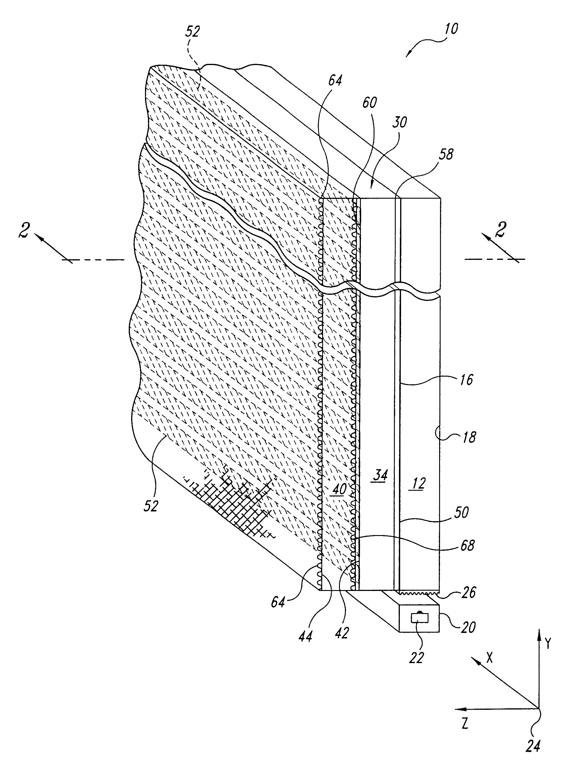
图1是根据本发明一部分观看屏的优选实施例的等比例图。Figure 1 is an isometric view of a preferred embodiment of a portion of a viewing screen in accordance with the present invention.
图2是沿着图1的2-2线所得到的图1观看屏的截面图。FIG. 2 is a cross-sectional view of the viewing screen of FIG. 1 taken along line 2-2 of FIG. 1 .
图3是图1观看屏的正面图。FIG. 3 is a front view of the viewing screen of FIG. 1. FIG.
图4是图1观看屏的等比例图,表示由光发生器产生的点光源的虚象位置和虚象随着观察者眼睛水平移动的移动方式。Fig. 4 is an isometric view of the viewing screen of Fig. 1 showing the position of the virtual image of the point light source produced by the light generator and the manner in which the virtual image moves as the observer's eyes move horizontally.
图5是沿着图4的5-5线得到的图4观看屏的截面图,表示从观看屏发散的光的垂直发散性和虚象随着观察者的眼睛移动的移动方式。5 is a cross-sectional view of the viewing screen of FIG. 4 taken along line 5-5 of FIG. 4, showing the vertical divergence of light emanating from the viewing screen and the manner in which virtual images move as the viewer's eyes move.
图6是图1观看屏的等比例图,表示虚象线的位置和由观看屏产生的整个虚象。Figure 6 is an isometric view of the viewing screen of Figure 1 showing the location of the virtual image lines and the overall virtual image produced by the viewing screen.
图7是图1的观看屏的等比例图,表示容许观看屏产生彩色图象的另一技术。Fig. 7 is an isometric view of the viewing screen of Fig. 1 illustrating another technique which allows the viewing screen to produce color images.
图8是包括图1的观看屏和给观看屏提供信号的电子系统的观看系统的方块图。8 is a block diagram of a viewing system including the viewing screen of FIG. 1 and electronics providing signals to the viewing screen.
图9是图1观看屏的等比例图,表示作为安装在观看屏上的集成电路的图8的电子系统。9 is an isometric view of the viewing screen of FIG. 1 showing the electronic system of FIG. 8 as an integrated circuit mounted on the viewing screen.
图10是表示使用图1的一对观看屏的虚拟现实观看系统的等比例图和方块图。10 is an isometric and block diagram illustrating a virtual reality viewing system using the pair of viewing screens of FIG. 1 .
图11是根据本发明的观看屏呈曲面的观看屏另一实施例的等比例图。Fig. 11 is an isometric view of another embodiment of a viewing screen having a curved viewing screen according to the present invention.
具体实施方式Detailed ways
本发明的优选实施例如图1中所示为单个观看屏10,应该明白,为了立体平面显示目的,可以把观看屏配置在每个眼睛的前面,如下所述。图1中示出了观看屏10的一部分,观看屏10包括高折射率透明材料例如铅玻璃或含高铅成分的玻璃的底板12。在本发明优选实施例中,底板12的折射率为1.68,厚度为2mm,当然也可以使用具有与此不同的折射率或尺寸的底板。虽然图1中所示底板12是平面型的,但是如下所述,底板不一定必须是平面型的。The preferred embodiment of the present invention is shown in Figure 1 as a
底板12具有前表面16和后表面18,前表面16是对着适于显示图象的位置的表面。细长的光发生器20沿着底板12的一边安装,从光发生器20,光选择性地从多个纵向隔开定位的区域的每个区域发射,其中每个区域都近似为点光源。光发生器20最好是由以合适间隔例如大约50微米间隔设置的直线阵列激光二极管22组成。但是,激光二极管22可以以其它间隔分隔开,光发生器20可以由其它装置组成,例如发光二极管(“LED”S)阵列。LED具有比激光二极管22宽的发射峰值,并且它们不具有与激光二极管22一样高的空间相干性。结果,当使用LED作为光发生器20时,与使用激光二极管22作为光发生器20的情况相比用观看屏10显示的图象可能不太鲜明。The
为了确定空间关系的清晰性的目的,建立如图1所示的直角坐标系24,其中底板12的前表面16位于由X轴和Y轴确定的平面内,其厚度沿着Z轴方向延伸,光发生器沿着X轴延伸。For the purpose of determining the clarity of the spatial relationship, a
在光发生器20和底板12的下边之间设置可以用常规方式全息形成的衍射元件26。所制造的衍射元件26应使从光发生器20发射的光以足够的角度被衍射,从而使光从分别形成在前和后表面16和18的空气/玻璃界面以全内反射穿过底板12传播。在本发明的最佳实施例中,光被衍射到相对Z轴72度的角度,这个角度大于在玻璃和空气之间的界面全内反射的临界角。但是,其它衍射角也可以用,只要它们能足以提供全内反射即可。而且,也可以使用其它器件代替衍射元件,包括棱镜(未示出)或透镜(未示出)。另外,光发射器20和衍射元件26可以不设置在底板12的边缘位置上。例如,光发生器20和衍射元件26可以设置在盖板12毗邻一边缘的前表面16上或后表面18上,只要衍射元件26能把光以所要求的角度直射入底板12,并且折射率调制器能用所得到的内部反射光束角度工作即可。Between the
折射率调制器30,例如常规全内反射(“TIR”)调制器,覆盖底板的前表面16。在本发明优选实施例中,折射率调制器30是设置在底板12和具有后表面42和前表面44的盖板40之间的液晶层。在底板12的前表面上形成单个导电电极50,同时在盖板40的后表面42上形成多个透明的水平带状电极52。每个带状电极52沿着X轴延伸,它们沿着Y轴彼此分隔开。电极50、52的位置也可以反过来,即带状电极52形成在底板12的前表面16上,而单个导电电极50形成在盖板40的后表面42上。电极50、52可以是由等于或小于1微米的薄层铟锡氧化物(“ITO”)制成,这种铟锡氧化物是导电的且透明的。在本发明优选实施例中,每个带状电极50宽约为45微米,厚约为100毫微米,并且它们以约5微米的间隙彼此分开。由于液晶34应该能够很快响应下述类型的调制,因此液晶34最好是铁电液晶。但是,也可以使用其它材料,例如包括:向列型液晶、电光介质、多量子阱介质、电于陷阱材料和光折射材料等。一般情况下,具有能在高和低状态之间转换的折射率的任何介质都能用作折射率调制30,代替液晶34。A
用例如旋压涂覆、浸渍、弯液面(meniscus)涂覆或蒸发的合适方法在电极50上涂聚合材料的定向层58。在优选实施例中,定向层58的厚度为500毫微米,但也可以使用更厚或更薄层。定向层58的分子用合适方式被定向在预定方向上,例如用压毡辊(felt-covered roller)(未示出)抛光。这些分子被定向为离开Y轴的合适方向上,例如在X-Y平面内离开Y轴22度。当液晶34与定向层58接触时,它们自已与分子的取向对准。当它们被定向层58的分子校准时,液晶34具有各向异性的折射率。An
虽然观看屏10的优选实例中使用具有按22度定向的分子的聚合材料层作为它的定向层58,但是应该明白,也可以使用其它定向角。在任何情况下,都应该为特殊的液晶优选抛光角,用于使相对于在底板12中传播的光的偏振测量的折射率的差值最大。而且,也可以使用其它方法定向液晶34。例如,带状电极52或高折射率涂层68的表面可以以适当角度抛光。而且,可以用以预定的定向角偏振的紫外光曝光来定向聚合物涂层(未示出)的分子。或者,带状电极52的表面可以用单层有机分子涂覆,然后用偏振的紫外光使有机分子交链。While the preferred example of
当在带状电极52之一和单个电极50之间加上一个极性的电压时,邻近已通电的带状电极52的液晶34的分子会按照两不同的取向之一排列,这取决于电场的极性。当分子根据一个极性的电场按第一取向排列时,液晶34将具有在给定方向上传播并具有特殊偏振状态的光的相对高的折射率。当分子根据相反极性的电场按第二取向排列时,液晶34将具有在相同给定方向上传播的光的相对低的折射率。当液晶34的折射率相对低时,穿过底板12传播的光从底板12的前表面16和液晶34之间的界面反射。但是,当液晶34的折射率足够高时,在底板12中传播的光不再从底板/液晶界面反射。而是,光射出底板12并进入液晶34且穿过带电带状电极52。在本发明优选实施例中,液晶34的折射率在1.55和1.64之间转换,这足以使折射率调制器30从反射状态转换到传输状态。在电极50和每个带状电极52之间的电场最好是如此产生的:即电极50接地,给每个带状电极52加上正的或负的电压。但是,带状电极52中之一可以选择性地接地并且单个电极50被激励,或者单个电极50和带状电极52中之一可以同时用合适的电压激励。When a voltage of one polarity is applied between one of the
盖板40最好具有高折射率,且最好是由高折射率玻璃制成。盖板40的折射率应该相对于液晶34的折射率足够高,从而使从液晶34发射出的光穿过盖板40传播而不是从液晶/盖板界面反射。为了进一步防止光从盖板40的后表面42反射,或者为了容许盖板40由具有相对低折射率的普通钠钙玻璃制成,在带状电极52下面的盖板40的后表面上形成全息光学元件60。全息光学元件60最好是以常规方式腐蚀盖板40的后表面42形成的。如上所述,光从底板12以例如72度的角度进入液晶34。全息光学元件60在接近于Z轴即相对Z轴较小角度的方向上衍射光,从而使光不会从盖板40的前表面反射。全息光学元件60的衍射角也控制在观看屏10上可看见的虚象的位置,这将在下面更详细地描述。在盖板40的前表面上可以形成另一个全息光学元件64,原因如上。全息光学元件60、64可以用本领域公知的合适方式形成。
在全息光学元件60和带状电极52之间的盖板40的后表面42上最好也形成高折射率涂层68。涂层68的作用是把光从液晶34耦合到盖板40。
虽然在观看屏10的优选实施例中折射率调制器30使用矩形带状电极52在规定区域上控制液晶34的折射率,但是除了矩形以外的图形也可以使用,包括圆点形、弯曲设计、字符特征、和其它形状都可以使用。Although in the preferred embodiment of the
在工件中,每个激光二极管22沿着光发生器20依次被通电,以从沿着底板12的边缘扫描的基本点光源照亮底板12。但是,应该明白激光二极管22可以按照其它顺序点亮,例如交错图形。而且,一次可以不只点亮一个激光二极管22。实际上,由于每个激光二极管对应图象中的每个水平象素行的一个象素,因此,可以同时点亮所有的激光二极管。详细说明见下文,从激光二极管22发出的光的强度被调制到与使用观看屏10显示的图象的象素强度一致。In the workpiece, each
当光从一个或多个激光二极管22发出时,它将以例如72度的预定角度穿过底板12传播,如图2所示。由于光要进行全内反射,因此在它沿Y轴方向穿过底板12传播时,它从底板的表面16、18来回反射。When light is emitted from one or
在光沿Y轴方向穿过底板12传播时,它将在X轴方向沿着底板12的宽度传播开,如图3所示。在光从光发生器20已经传播实际距离之后,不管激光二极管22是否已产生光,底板12的整个宽度都被点亮。但是,如观看屏10中显示的那样,光源即通电的激光二极管22的水平位置将会变化,这取决于哪个激光二极管22发光。本质上,如下面的进一步说明,图象中被照亮的象素的水平位置对应于发光的激光二极管22的水平位置。因为在优选实施例中光束是发散的,所以图象象素的水平位置取决于激光二极管的位置和通电电极的垂直位置。As light propagates through the
再回到图2,光穿过底板12传播,直到它到达通电带状电极52。通电带状电极52在液晶34中产生具有使液晶34的折射率增加的极性的场。(为了清楚起见,图2中只示出该通电带状电极52)。结果,由于存在全息光学元件60,光穿过液晶34和通电带状电极52传播进入盖板40。进入盖板40的光穿过盖板40的前表面44,在那里,光被全息光学元件64衍射,如下面的详细说明。Returning again to FIG. 2 , light propagates through
如果所有的激光二极管22同时发光,那么在对应通电带状电极52的位置上,穿过盖板40可见到水平光带。但是,如果只有单个激光二极管22发光,那么穿过通电带状电极52显示的发光的激光二极管22的虚象是具有对应该激光二极管22水平位置的水平位置的一个光点。通过依次点亮每个激光二极管22,穿过通电带状电极52显示的光点沿着X轴穿过盖板40的前表面44水平扫描。用类似于阴极射线管光栅扫描的方法,由激光二极管22发出的光的强度可以调制,以控制水平扫描光点的强度,从而形成图象的一行象素。虽然可以用其它方式例如交错图形来给带状电极52通电,但仍可以通过依次给每个带状电极52通电来连续扫描各行。但是,通常一次只给一条带状电极52通电,不管是一个或多个激光二极管22发光。If all
发光的激光二极管22的视在光源即激光二极管22的虚象70,在如图4中所示的位置。在观看屏10后面的虚象70的距离相当于在光分别从底板12的前表面16和后表面18来回反射时,光从激光二极管22传输的总距离,以及从盖板40发散的光的发散角。发光的激光二极管22的虚象70的水平位置与发光的激光二极管22的水平位置一致。但是,因为从发光的激光二极管22发出的光在穿过底板12传播时会发散,即变宽,所以从盖板40射出的光水平发散,从而在水平位置范围内可见到虚象70。在现察者的眼睛76从一边移向另一边时,即从位置76到位置76’,虚象70的水平位置不会相对于显示器变化,在正常使用过程中,当眼睛76或76’的位置相对于观看器件保持静止时,虚象70的水平位置相对眼睛将保持静止。这样,当眼睛76或76’静止时,在一特定水平线中的虚象点70的水平位置将只随着发光的激光二极管22的水平位置变化。The apparent light source of the emitting
发光的激光二极管22的虚象70的垂直位置对应于光从盖板40发射的角度。但是,在没有全息光学元件60、64时,从盖板40射出的光不会显著发散,从而使虚象70基本上只从一个垂直位置可以看到。当眼睛76处于如图4中所示位置时,将能看到虚象70,且位于70处。但是,当眼睛位于76’位置时,不能看到虚象70。而且,当给另一带状电极52’通电时,在眼睛位于76位置时也看不到虚象70。而只有当眼睛76处于穿过虚象70和通电的带状电极52’延伸的平面内时才能看到虚象70。The vertical position of the
为了用观看屏10显示图象,在激光二极管22被选择通电且所有带状电极被选择通电时,一定可以看到激光二极管22的虚象。然而,在每个带状电极52被通电以把眼睛76放在显示虚象70的校正垂直位置上时,观察者不能移动他的或她的头。为此,设计全息光学元件64和任选的全息光学元件60,从而在整个垂直发散角80的范围衍射从盖板40射出的光,如图5所示,只要眼睛76位于发散角80范围内,就可看见虚象70。虚象70的垂直位置将随着观察者的眼睛76上下移动而改变。这样,当眼睛76在76’和76”之间移动时,虚象70将相应地在76’和76”之间移动。但是,在正常使用过程中,当眼睛76的位置相对于观看器件保持静止时,虚象70的垂直位置将保持静止。这样,当眼睛76静止时,虚象70的垂直位置将只随着通电的带状电极52的垂直位置变化。In order to display an image with
在优选实施例中,全息光学元件64的构成应使在带状电极52区域中穿过盖板40射出的光从观看屏10后面10英尺的点出现发散。但是也可以使用其它的发散角和虚象距离。这样,当激光二板管22以变化的强度依次发光,同时单个带状电极52被通电时,如图6所示,将会在观看屏10后面10英尺处产生虚象行90。当激光二极管22依次发光且每个带状电极52依次被通电时,如图6所示,将在观看屏10后面10英尺处产生虚象屏94。只要适当调制从激光二级管22发射的光强度,就可以在虚象屏94上产生相应于视频信号的图象。In the preferred embodiment, holographic
但是,实际上,器件的场深度应很大,以使穿过一个眼睛显示的虚象将出现在从几英尺到无限远的预定距离内。深度的实际外部特性几乎完全取决于从提供给两只眼睛的不同图象获得的立体信号。In practice, however, the depth of field of the device should be large so that a virtual image displayed through one eye will appear within a predetermined distance from a few feet to infinity. The actual appearance of depth depends almost entirely on the stereo signals obtained from the different images provided to the two eyes.
用在光发生器20中的激光二极管22可以是单颜色的,从而产生单色图象但是,如可以使用具有不同颜色,例如红、绿和蓝的激光二极管22以产生彩色图象。也可以通过其它方式产生彩色图象,例如,通过使用发白光或至少含红、蓝和绿颜色的光的光发生器20。参照图7,每个带状电极52分成三个子电极98a,98b,98c,它们每个分别使盖板40发红、绿和蓝光。(为清楚起见,图7中只示出一个带状电极52)。由盖板40在每个子电极98a,98b,98c的区域中发出的颜色可以通过全息光学元件64的特性来控制,或者通过在各个子电极98a,98b,98c上设置不同颜色滤光器来控制。光发生器20为每个子电极分别调制以改变在虚象94的每个象素中的红、蓝和绿的相对浓度。The
参照图8,观看系统10包括观看屏10和电子系统104,电子系统104通过例如电缆106等合适装置耦合到观看屏10上。电子系统104包括视频信号发生器110,信号发生器110可以是例如电视接收机、视频录象机、计算机等。视频发生器110在线路112上提供视频信号,例如常规NTSC视频信号。线路112上的视频信号输入与激光二极管22和带状电极52耦合的处理单元116。处理单元116的设计是本领域熟练人员很容易做出的,为简便起见不再详细说明。例如,NTSC视频信号可以用由时钟122驱动的常规取样和保持(“S/H”)电路120连续取样,而每个样值用于调制各个激光二极管22a-m的强度。也接收视频信号的行计数器124在每个视频帧开始时复位,并由NTSC视频信号中的水平回扫脉冲增值。对应于行计数器124中计数的数字信号输入具有多个输出的解码器126,其每个输出与各个带状电极52a-n耦合。解码器126在对应数字信号的计数值的一个输出上产生带状电极信号。当来自行计数器124的数字信号的值用每个水平回扫脉冲依次增加时,带状电极52依次被通电。在每个带状电极52被通电的过程中,每个激光二级管22对应来自S/H电路120的它的各个样值在某一强度依次被通电,以产生相应的扫描光栅行。在显示彩色图象时,可以用常规装置从视频信号获得分离的红、蓝和绿调制信号,并用于分别驱动红、蓝和绿激光二极管22。Referring to FIG. 8 ,
激光二极管22和带状电极52的寻址速度当然取决于存在于观看屏10中的激光二极管22和带状电极52的数量和为以可接受的水平保持荧光屏闪烁所需要的图象更新速度。激光二极管22和带状电极52的寻址速度应该很快,从而足以使虚象以每秒多于24次地被更新。为了用3种颜色的激光二板管22形成800×600分辨率的全彩色图象,需要每1/30秒给800个带状电极52通电,或者以1/(24000),即1/(30×800)的速度,也就是每个带状电极52所用时间约为42微秒。这个速度是在铁电液晶的转换速度范围内的。在每个42微秒过程中,需要调制1800个激光二极管,即600×3种颜色,这就需要以每个激光二极管22大约23毫微秒的速度,但是如果用于形成每个象素的3个激光二极管的所有3个同时通电,则每个激光二极管22的时间仅约为70毫微秒。由激光二极管22发出的光的强度可以用适当方法控制,例如通过控制加在激光二极管22的驱动电压的幅度或负载周期。The addressing speed of
虽然在每个带状电极52通电时并在给下一个带状电极52通电之前,电子系统104最好驱动光发生器20中的每个激光二极管,但是电子系统104也可以采用其它工作模式。例如,如上所述,激光二极管22的发光和带状电极52的通电可以交错进行,即:先依次选择所有偶数的二极管22和/或电极52,接下来再选择所有奇数的二极管22和/或电极52。而且,在驱动下一激光二极管22之前驱动光发生器20中的一个激光管22时,电子系统104可以给每个带状电极52通电,虽然这种方法使从NTSC视频信号获得的并施加于激光二极管22的信号复杂化。While
虽然电子系统104可以通过电缆106耦合到观看屏10,如图8所示,但是最好由作为直接连接到盖板40上的集成电路芯片120来完成,如图9所示。这种结构不需要使用体积庞大和笨重的连接器和多芯电缆,并消除了它们附带的可靠性问题。视频信号可以通过合适的装置例如同芯电缆132、光纤、无线电或红外耦合器件,耦合到集成电路芯片130上。While
一对观看屏10特别适用于虚拟现实观看系统140中,如图10所示。观看系统140包括具有一对观看屏10a,10b的虚拟现实观看器件142,观看屏10a,10b安装在合适的框架144中并通过合适装置146耦合到电子系统104上,包括上述耦合器件。本领域内众所周知,给观看屏10a和10b加上不同视频信号,观察者就能看见不同的图象,这些图象一起产生三维或立体图象。虚拟现实观看器件142最好还包括常规传感器148,它能产生指示观看器件140的位置和方向的信号。这个信号利用合适的装置150耦合到电子系统104上,最好是利用把与视频信号耦合到观看屏10上的方法相同的方法。与电子系统104(或一部分电子系统104)耦合的计算机156用于调节视频信号,从而使立体平面图象对应于虚拟现实观看器件142的位置和方向。能产生立体平面视频信号的计算机和软件是公知的,它们可以用在观看系统140中。A pair of viewing screens 10 is particularly suitable for use in a virtual
图1-10中所示的观看屏10使用了平面形的底板12和盖板40。但是,如图11所示,观看屏160可以使用曲面而不是平面形的底板162和盖板164。如果光发生器166发出的光被用作参考光束,以形成盖板164上的全息光学元件168,那么底板162中的变形或非均匀性将会自动校正。因而,即使底板162变形,曲面观看屏160也能显示基本不变形的图象。The
形成全息光学元件168的方法也可见图11。光发生器162发出的光用作参考光束170以与从光源发出的物光束172干涉,其中光源发出的光相对于光发生器162发出的光是相干的。盖板164上的摄影记录介质174记录参考光束170和物光束172之间的干涉,并且所得到的记录的干涉用作全息光学元件168。用作全息光学元件168的记录干涉图形结合盖板164中的变形,包括那些由盖板164的曲率引起的变形。当全息光学元件168被光发生器162发出的光连续照射时,光发生器162的虚象就以最小的变形再现出来。A method of forming holographic
除了液晶分子的电场对准效应外,折射率调制器还可以使用其它现象。实际上,任何影响折射率的现象都可以使用,例如电泳现象、光折射效应、温度-控制折射率、化学变化、压缩(compression)。在优选实施例中使用液晶,是因为液晶调制器已经达到商业发生的高水平。但是,与光偏振无关的效应将以更宽的视角提供显示。In addition to the electric field alignment effect of liquid crystal molecules, refractive index modulators can also use other phenomena. Virtually any phenomenon that affects the refractive index can be used, such as electrophoretic phenomena, photorefractive effects, temperature-controlled refractive index, chemical changes, compression. Liquid crystals are used in the preferred embodiment because liquid crystal modulators have reached a high level of commercial occurrence. However, effects independent of the polarization of the light will provide displays with wider viewing angles.
Claims (53)
Applications Claiming Priority (2)
| Application Number | Priority Date | Filing Date | Title |
|---|---|---|---|
| US856022 | 1997-05-13 | ||
| US08/856,022 US5973727A (en) | 1997-05-13 | 1997-05-13 | Video image viewing device and method |
Publications (2)
| Publication Number | Publication Date |
|---|---|
| CN1206218A CN1206218A (en) | 1999-01-27 |
| CN1184503C true CN1184503C (en) | 2005-01-12 |
Family
ID=25322706
Family Applications (1)
| Application Number | Title | Priority Date | Filing Date |
|---|---|---|---|
| CN98109836.3A Expired - Lifetime CN1184503C (en) | 1997-05-13 | 1998-05-13 | Video image viewing device and method |
Country Status (3)
| Country | Link |
|---|---|
| US (2) | US5973727A (en) |
| JP (1) | JP4181660B2 (en) |
| CN (1) | CN1184503C (en) |
Cited By (1)
| Publication number | Priority date | Publication date | Assignee | Title |
|---|---|---|---|---|
| CN101720447B (en) * | 2007-04-30 | 2013-01-09 | 视瑞尔技术公司 | Light modulator for representing complex-valued data |
Families Citing this family (109)
| Publication number | Priority date | Publication date | Assignee | Title |
|---|---|---|---|---|
| US5973727A (en) * | 1997-05-13 | 1999-10-26 | New Light Industries, Ltd. | Video image viewing device and method |
| US6271526B1 (en) * | 1998-10-15 | 2001-08-07 | California Institute Of Technology | Efficient radiation coupling to quantum-well radiation-sensing array via evanescent waves |
| JP2004519718A (en) * | 2000-10-23 | 2004-07-02 | モトローラ・インコーポレイテッド | Display device with switchable semi-transmissive reflective part and visible on both sides |
| GB0108838D0 (en) * | 2001-04-07 | 2001-05-30 | Cambridge 3D Display Ltd | Far field display |
| WO2002086591A1 (en) * | 2001-04-23 | 2002-10-31 | Reveo, Inc. | Image display system and electrically actuatable image combiner therefor |
| US7101048B2 (en) * | 2001-09-25 | 2006-09-05 | Cambridge Flat Protection Displays Limited | Flat-panel projection display |
| US6707958B2 (en) | 2001-11-20 | 2004-03-16 | Agilent Technologies, Inc. | Biochemical assay device using frustrated total internal reflection modulator with an imaging optical waveguide |
| US6958861B1 (en) * | 2002-12-02 | 2005-10-25 | The Ohio State University | Method and apparatus for combining optical beams |
| US7236238B1 (en) | 2002-12-02 | 2007-06-26 | The Ohio State University | Method and apparatus for monitoring the quality of optical links |
| US7417782B2 (en) * | 2005-02-23 | 2008-08-26 | Pixtronix, Incorporated | Methods and apparatus for spatial light modulation |
| US7227568B2 (en) * | 2004-04-03 | 2007-06-05 | Li Sun | Dual polarizing light filter for 2-D and 3-D display |
| US7430347B2 (en) * | 2004-07-16 | 2008-09-30 | The Ohio State University | Methods, systems, and apparatuses for optically generating time delays in signals |
| US7633670B2 (en) * | 2004-07-16 | 2009-12-15 | The Ohio State University | Methods, systems, and devices for steering optical beams |
| US20060034567A1 (en) * | 2004-07-16 | 2006-02-16 | Anderson Betty L | Optical beam combiner |
| CN100395634C (en) * | 2004-08-07 | 2008-06-18 | 鸿富锦精密工业(深圳)有限公司 | Backlight module |
| CN1740951A (en) * | 2004-08-25 | 2006-03-01 | 西门子公司 | Apparatus for device control using human eyes |
| WO2006059264A1 (en) * | 2004-11-30 | 2006-06-08 | Koninklijke Philips Electronics N.V. | Illumination system using a laser source for a display device |
| US7586560B2 (en) * | 2005-01-03 | 2009-09-08 | Intel Corporation | Display using light guide and refractive index control |
| WO2006086819A1 (en) * | 2005-02-15 | 2006-08-24 | Dac Thong Bui | 3d digital vision |
| US20070205969A1 (en) | 2005-02-23 | 2007-09-06 | Pixtronix, Incorporated | Direct-view MEMS display devices and methods for generating images thereon |
| US9229222B2 (en) | 2005-02-23 | 2016-01-05 | Pixtronix, Inc. | Alignment methods in fluid-filled MEMS displays |
| US7999994B2 (en) | 2005-02-23 | 2011-08-16 | Pixtronix, Inc. | Display apparatus and methods for manufacture thereof |
| US9082353B2 (en) | 2010-01-05 | 2015-07-14 | Pixtronix, Inc. | Circuits for controlling display apparatus |
| US9158106B2 (en) | 2005-02-23 | 2015-10-13 | Pixtronix, Inc. | Display methods and apparatus |
| US8310442B2 (en) | 2005-02-23 | 2012-11-13 | Pixtronix, Inc. | Circuits for controlling display apparatus |
| US8519945B2 (en) | 2006-01-06 | 2013-08-27 | Pixtronix, Inc. | Circuits for controlling display apparatus |
| US9087486B2 (en) | 2005-02-23 | 2015-07-21 | Pixtronix, Inc. | Circuits for controlling display apparatus |
| US9261694B2 (en) | 2005-02-23 | 2016-02-16 | Pixtronix, Inc. | Display apparatus and methods for manufacture thereof |
| US7463244B2 (en) * | 2005-05-19 | 2008-12-09 | Avago Technologies Ecbu Ip (Singapore) Pte. Ltd. | Optical mouse and method for removing contaminants in an optical mouse |
| GB0522968D0 (en) | 2005-11-11 | 2005-12-21 | Popovich Milan M | Holographic illumination device |
| US7515344B2 (en) * | 2006-01-04 | 2009-04-07 | Vuzlx Corporation | Binocular display with improved contrast uniformity |
| US8526096B2 (en) | 2006-02-23 | 2013-09-03 | Pixtronix, Inc. | Mechanical light modulators with stressed beams |
| GB0718706D0 (en) | 2007-09-25 | 2007-11-07 | Creative Physics Ltd | Method and apparatus for reducing laser speckle |
| US7911671B2 (en) * | 2006-05-10 | 2011-03-22 | The Ohio State University | Apparatus and method for providing true time delay in optical signals using a Fourier cell |
| US7630598B2 (en) * | 2006-05-10 | 2009-12-08 | The Ohio State University | Apparatus and method for providing an optical cross-connect |
| WO2008024691A2 (en) * | 2006-08-22 | 2008-02-28 | Li Sun | 2-d and 3-d display |
| US8139103B2 (en) * | 2006-11-11 | 2012-03-20 | Vuzix Corporation | Traveling lens for video display |
| KR20090102783A (en) * | 2006-12-27 | 2009-09-30 | 데이진 가부시키가이샤 | Polarizing element and liquid crystal display device |
| US9176318B2 (en) | 2007-05-18 | 2015-11-03 | Pixtronix, Inc. | Methods for manufacturing fluid-filled MEMS displays |
| US8014050B2 (en) * | 2007-04-02 | 2011-09-06 | Vuzix Corporation | Agile holographic optical phased array device and applications |
| US8430525B2 (en) * | 2007-05-10 | 2013-04-30 | Koninklijke Philips Electronics N.V. | Illumination assembly for shop illumination |
| US8305387B2 (en) * | 2007-09-07 | 2012-11-06 | Texas Instruments Incorporated | Adaptive pulse-width modulated sequences for sequential color display systems |
| JP5152718B2 (en) * | 2007-12-26 | 2013-02-27 | Nltテクノロジー株式会社 | Image display device and terminal device |
| RU2378673C1 (en) * | 2008-04-03 | 2010-01-10 | Владимир Исфандеярович Аджалов | Image visualisation method and device to this end |
| US8169679B2 (en) | 2008-10-27 | 2012-05-01 | Pixtronix, Inc. | MEMS anchors |
| EP2200332A1 (en) | 2008-12-17 | 2010-06-23 | Robert Bosch GmbH | Autostereoscopic display |
| US8059342B2 (en) * | 2009-04-03 | 2011-11-15 | Vuzix Corporation | Beam segmentor for enlarging viewing aperture of microdisplay |
| US11726332B2 (en) | 2009-04-27 | 2023-08-15 | Digilens Inc. | Diffractive projection apparatus |
| US9335604B2 (en) | 2013-12-11 | 2016-05-10 | Milan Momcilo Popovich | Holographic waveguide display |
| US11204540B2 (en) | 2009-10-09 | 2021-12-21 | Digilens Inc. | Diffractive waveguide providing a retinal image |
| WO2012136970A1 (en) | 2011-04-07 | 2012-10-11 | Milan Momcilo Popovich | Laser despeckler based on angular diversity |
| US8548290B2 (en) | 2011-08-23 | 2013-10-01 | Vuzix Corporation | Dynamic apertured waveguide for near-eye display |
| US10670876B2 (en) | 2011-08-24 | 2020-06-02 | Digilens Inc. | Waveguide laser illuminator incorporating a despeckler |
| WO2016020630A2 (en) | 2014-08-08 | 2016-02-11 | Milan Momcilo Popovich | Waveguide laser illuminator incorporating a despeckler |
| US20140204455A1 (en) | 2011-08-24 | 2014-07-24 | Milan Momcilo Popovich | Wearable data display |
| JP5344069B2 (en) * | 2011-08-29 | 2013-11-20 | 株式会社デンソー | Head-up display device |
| US20140285886A1 (en) * | 2011-11-02 | 2014-09-25 | Jeremy J. DePalma | Stereoscopic viewer |
| US9709829B2 (en) | 2011-11-18 | 2017-07-18 | Vuzix Corporation | Beam steering device |
| WO2013102759A2 (en) | 2012-01-06 | 2013-07-11 | Milan Momcilo Popovich | Contact image sensor using switchable bragg gratings |
| WO2013163347A1 (en) | 2012-04-25 | 2013-10-31 | Rockwell Collins, Inc. | Holographic wide angle display |
| WO2013167864A1 (en) | 2012-05-11 | 2013-11-14 | Milan Momcilo Popovich | Apparatus for eye tracking |
| JP5973788B2 (en) * | 2012-05-28 | 2016-08-23 | 任天堂株式会社 | Information processing program, information processing apparatus, information processing system, and information processing method |
| US9933684B2 (en) | 2012-11-16 | 2018-04-03 | Rockwell Collins, Inc. | Transparent waveguide display providing upper and lower fields of view having a specific light output aperture configuration |
| US9134552B2 (en) | 2013-03-13 | 2015-09-15 | Pixtronix, Inc. | Display apparatus with narrow gap electrostatic actuators |
| US9392129B2 (en) * | 2013-03-15 | 2016-07-12 | John Castle Simmons | Light management for image and data control |
| WO2014188149A1 (en) | 2013-05-20 | 2014-11-27 | Milan Momcilo Popovich | Holographic waveguide eye tracker |
| US9727772B2 (en) | 2013-07-31 | 2017-08-08 | Digilens, Inc. | Method and apparatus for contact image sensing |
| US10359736B2 (en) | 2014-08-08 | 2019-07-23 | Digilens Inc. | Method for holographic mastering and replication |
| US10241330B2 (en) | 2014-09-19 | 2019-03-26 | Digilens, Inc. | Method and apparatus for generating input images for holographic waveguide displays |
| US10423222B2 (en) | 2014-09-26 | 2019-09-24 | Digilens Inc. | Holographic waveguide optical tracker |
| WO2016113533A2 (en) | 2015-01-12 | 2016-07-21 | Milan Momcilo Popovich | Holographic waveguide light field displays |
| CN107873086B (en) | 2015-01-12 | 2020-03-20 | 迪吉伦斯公司 | Environmentally isolated waveguide display |
| EP3248026B1 (en) | 2015-01-20 | 2019-09-04 | DigiLens Inc. | Holographic waveguide lidar |
| US9632226B2 (en) | 2015-02-12 | 2017-04-25 | Digilens Inc. | Waveguide grating device |
| US10459145B2 (en) | 2015-03-16 | 2019-10-29 | Digilens Inc. | Waveguide device incorporating a light pipe |
| WO2016152637A1 (en) * | 2015-03-20 | 2016-09-29 | アルプス電気株式会社 | Image display device |
| WO2016156776A1 (en) | 2015-03-31 | 2016-10-06 | Milan Momcilo Popovich | Method and apparatus for contact image sensing |
| EP3359999A1 (en) | 2015-10-05 | 2018-08-15 | Popovich, Milan Momcilo | Waveguide display |
| EP3398007B1 (en) | 2016-02-04 | 2024-09-11 | DigiLens, Inc. | Waveguide optical tracker |
| WO2017162999A1 (en) | 2016-03-24 | 2017-09-28 | Popovich Milan Momcilo | Method and apparatus for providing a polarization selective holographic waveguide device |
| EP3433658B1 (en) | 2016-04-11 | 2023-08-09 | DigiLens, Inc. | Holographic waveguide apparatus for structured light projection |
| CN105702171A (en) * | 2016-04-19 | 2016-06-22 | 京东方科技集团股份有限公司 | Display device and display method |
| CN106324868A (en) * | 2016-10-31 | 2017-01-11 | 京东方科技集团股份有限公司 | Display panel, driving method thereof and display device |
| US11513350B2 (en) | 2016-12-02 | 2022-11-29 | Digilens Inc. | Waveguide device with uniform output illumination |
| WO2018129398A1 (en) | 2017-01-05 | 2018-07-12 | Digilens, Inc. | Wearable heads up displays |
| CN116149058A (en) | 2017-10-16 | 2023-05-23 | 迪吉伦斯公司 | System and method for multiplying image resolution of pixellated display |
| WO2019136476A1 (en) | 2018-01-08 | 2019-07-11 | Digilens, Inc. | Waveguide architectures and related methods of manufacturing |
| US10732569B2 (en) | 2018-01-08 | 2020-08-04 | Digilens Inc. | Systems and methods for high-throughput recording of holographic gratings in waveguide cells |
| EP3710894B1 (en) | 2018-01-08 | 2025-07-30 | Digilens Inc. | Methods for fabricating optical waveguides |
| CN111615655B (en) | 2018-01-08 | 2023-03-21 | 迪吉伦斯公司 | System and method for manufacturing waveguide unit |
| CN108303802B (en) * | 2018-01-30 | 2019-11-05 | 吉林大学 | A kind of intelligent reading sheet devices of magnetic resonance imaging |
| WO2019178614A1 (en) | 2018-03-16 | 2019-09-19 | Digilens Inc. | Holographic waveguides incorporating birefringence control and methods for their fabrication |
| US10491890B1 (en) * | 2018-05-14 | 2019-11-26 | Dell Products L.P. | Systems and methods for automatic adjustment for vertical and rotational imbalance in augmented and virtual reality head-mounted displays |
| US11402801B2 (en) | 2018-07-25 | 2022-08-02 | Digilens Inc. | Systems and methods for fabricating a multilayer optical structure |
| CN109164636B (en) * | 2018-08-15 | 2021-04-09 | 华为技术有限公司 | a display device |
| US20200225471A1 (en) | 2019-01-14 | 2020-07-16 | Digilens Inc. | Holographic Waveguide Display with Light Control Layer |
| US20200247017A1 (en) | 2019-02-05 | 2020-08-06 | Digilens Inc. | Methods for Compensating for Optical Surface Nonuniformity |
| KR20250150160A (en) | 2019-02-15 | 2025-10-17 | 디지렌즈 인코포레이티드. | Methods and apparatuses for providing a holographic waveguide display using integrated gratings |
| US20220283377A1 (en) | 2019-02-15 | 2022-09-08 | Digilens Inc. | Wide Angle Waveguide Display |
| KR20210134763A (en) | 2019-03-12 | 2021-11-10 | 디지렌즈 인코포레이티드. | Holographic waveguide backlights and related manufacturing methods |
| KR20220016990A (en) | 2019-06-07 | 2022-02-10 | 디지렌즈 인코포레이티드. | Waveguides incorporating transmission and reflection gratings and related manufacturing methods |
| EP4004646A4 (en) | 2019-07-29 | 2023-09-06 | Digilens Inc. | METHODS AND APPARATUS FOR MULTIPLYING THE IMAGE RESOLUTION AND FIELD OF VIEW OF A PIXELATED DISPLAY SCREEN |
| KR20250030038A (en) | 2019-08-29 | 2025-03-05 | 디지렌즈 인코포레이티드. | Evacuating bragg gratings and methods of manufacturing |
| US12222499B2 (en) | 2020-12-21 | 2025-02-11 | Digilens Inc. | Eye glow suppression in waveguide based displays |
| US12399326B2 (en) | 2021-01-07 | 2025-08-26 | Digilens Inc. | Grating structures for color waveguides |
| US12158612B2 (en) | 2021-03-05 | 2024-12-03 | Digilens Inc. | Evacuated periodic structures and methods of manufacturing |
| US20230393329A1 (en) * | 2022-06-03 | 2023-12-07 | Meta Platforms Technologies, Llc | Waveguide with organic solid crystal substrate |
| US12510704B2 (en) * | 2022-07-20 | 2025-12-30 | Meta Platforms Technologies, Llc | Waveguide with birefringent organic solid crystal layer |
| WO2024130211A1 (en) * | 2022-12-15 | 2024-06-20 | Massachusetts Institute Of Technology | Non-planar metasurfaces and related fabrication methods |
Family Cites Families (16)
| Publication number | Priority date | Publication date | Assignee | Title |
|---|---|---|---|---|
| US5680233A (en) * | 1994-04-21 | 1997-10-21 | Reveo, Inc. | Image display systems having direct and projection viewing modes |
| US5223925A (en) * | 1990-10-28 | 1993-06-29 | Tomohiko Hattori | Autostereoscopic system |
| JP2935290B2 (en) * | 1991-06-07 | 1999-08-16 | 日本電気株式会社 | Display device using flat display panel |
| KR960013313B1 (en) * | 1991-07-12 | 1996-10-02 | 가부시키가이샤 한도오따이 에네루기 겐큐쇼 | Electro-optical display |
| WO1995005052A1 (en) * | 1993-08-09 | 1995-02-16 | Jens Ole Sorensen | Stereo-optic image display system with enhanced resolution |
| US5534950A (en) * | 1993-10-04 | 1996-07-09 | Laser Power Corporation | High resolution image projection system and method employing lasers |
| GB9323878D0 (en) * | 1993-11-19 | 1994-01-05 | Travis Adrian R L | Colour 3d display |
| DE4413829A1 (en) * | 1994-04-20 | 1995-10-26 | Deutsche Forsch Luft Raumfahrt | Device for generating an image |
| US5647036A (en) * | 1994-09-09 | 1997-07-08 | Deacon Research | Projection display with electrically-controlled waveguide routing |
| US5544268A (en) * | 1994-09-09 | 1996-08-06 | Deacon Research | Display panel with electrically-controlled waveguide-routing |
| GB2296400A (en) * | 1994-12-16 | 1996-06-26 | Sharp Kk | Autostereoscopic display having a high resolution 2D mode |
| US5543862A (en) * | 1995-01-23 | 1996-08-06 | Calvest Associates, Inc. | Video display and image intensifier system |
| US5886675A (en) * | 1995-07-05 | 1999-03-23 | Physical Optics Corporation | Autostereoscopic display system with fan-out multiplexer |
| JP3146138B2 (en) * | 1995-08-30 | 2001-03-12 | シャープ株式会社 | Reflective liquid crystal display device and information terminal equipment |
| US5771321A (en) * | 1996-01-04 | 1998-06-23 | Massachusetts Institute Of Technology | Micromechanical optical switch and flat panel display |
| US5973727A (en) * | 1997-05-13 | 1999-10-26 | New Light Industries, Ltd. | Video image viewing device and method |
-
1997
- 1997-05-13 US US08/856,022 patent/US5973727A/en not_active Expired - Lifetime
-
1998
- 1998-05-12 JP JP12929598A patent/JP4181660B2/en not_active Expired - Lifetime
- 1998-05-13 CN CN98109836.3A patent/CN1184503C/en not_active Expired - Lifetime
-
1999
- 1999-07-16 US US09/354,968 patent/US6181367B1/en not_active Expired - Lifetime
Cited By (1)
| Publication number | Priority date | Publication date | Assignee | Title |
|---|---|---|---|---|
| CN101720447B (en) * | 2007-04-30 | 2013-01-09 | 视瑞尔技术公司 | Light modulator for representing complex-valued data |
Also Published As
| Publication number | Publication date |
|---|---|
| JP4181660B2 (en) | 2008-11-19 |
| CN1206218A (en) | 1999-01-27 |
| US6181367B1 (en) | 2001-01-30 |
| JPH11168757A (en) | 1999-06-22 |
| US5973727A (en) | 1999-10-26 |
Similar Documents
| Publication | Publication Date | Title |
|---|---|---|
| CN1184503C (en) | Video image viewing device and method | |
| US11747719B2 (en) | Diffractive waveguide providing structured illumination for object detection | |
| US10409144B2 (en) | Diffractive waveguide providing structured illumination for object detection | |
| US9075184B2 (en) | Compact edge illuminated diffractive display | |
| US5410345A (en) | Stroboscopic illumination system for video displays | |
| CN106068533B (en) | The control of directional display | |
| US6137456A (en) | Electronic display device for simultaneously displaying 2D and 3D images | |
| KR100702904B1 (en) | Surface light source and liquid crystal display device using the surface light source | |
| JP4600260B2 (en) | Liquid crystal display | |
| CN108431670A (en) | Surface Features for Imaging Directional Backlighting | |
| US6278425B1 (en) | Single array edge intersecting beam display panel | |
| JP2018511148A (en) | Display device having output directivity control, and backlight and light directing method for such display device | |
| US6215464B1 (en) | Stereoscopic intersecting beam phosphorous display system | |
| CN108287388A (en) | Light guide plate, backlight module, display device and its driving method | |
| JP4483233B2 (en) | Surface light source and liquid crystal display device | |
| JP4501625B2 (en) | Surface light source and liquid crystal display device | |
| JP3506418B2 (en) | Display device | |
| Travis et al. | Flat projection for 3-D | |
| JP3539717B2 (en) | Display shooting device | |
| JP4600219B2 (en) | Driving method of liquid crystal display device | |
| KR101855258B1 (en) | Dynamic Thin Flat Type Light-Beam Deflector | |
| JP5397334B2 (en) | Driving method of display device | |
| KR20030075321A (en) | Autostereoscopic display apparatus | |
| JP2002287088A (en) | Three-dimensional video display device | |
| JP4407176B2 (en) | Display device |
Legal Events
| Date | Code | Title | Description |
|---|---|---|---|
| C06 | Publication | ||
| PB01 | Publication | ||
| C10 | Entry into substantive examination | ||
| SE01 | Entry into force of request for substantive examination | ||
| C14 | Grant of patent or utility model | ||
| GR01 | Patent grant | ||
| ASS | Succession or assignment of patent right |
Owner name: VUZIX CO.,LTD. Free format text: FORMER OWNER: NOVEL LIGHT INDUSTRY CO., LTD. Effective date: 20090828 |
|
| C41 | Transfer of patent application or patent right or utility model | ||
| TR01 | Transfer of patent right |
Effective date of registration: 20090828 Address after: American New York Patentee after: Vuzix company Address before: Washington, USA Patentee before: New Light Industries, Ltd. |
|
| CX01 | Expiry of patent term | ||
| CX01 | Expiry of patent term |
Granted publication date: 20050112 |