CN1182503C - Speech active display plate - Google Patents
Speech active display plate Download PDFInfo
- Publication number
- CN1182503C CN1182503C CNB031149995A CN03114999A CN1182503C CN 1182503 C CN1182503 C CN 1182503C CN B031149995 A CNB031149995 A CN B031149995A CN 03114999 A CN03114999 A CN 03114999A CN 1182503 C CN1182503 C CN 1182503C
- Authority
- CN
- China
- Prior art keywords
- plane
- light source
- voice
- luminous plaque
- incidence
- Prior art date
- Legal status (The legal status is an assumption and is not a legal conclusion. Google has not performed a legal analysis and makes no representation as to the accuracy of the status listed.)
- Expired - Fee Related
Links
Images


Landscapes
- Illuminated Signs And Luminous Advertising (AREA)
- Toys (AREA)
Abstract
The present invention discloses a speech luminous display plate which comprises a light source (1), a luminous plate (2) and a control circuit (3). The present invention is characterized in that the lateral surface of the luminous plate (2) is provided with an opening (4) which is used for holding the light source (1), and a plurality of concave holes (5) are arranged on the plane surface of the luminous plate (2). An incident surface (6) corresponding to light rays for the concave holes (5) is an inclined surface which is formed into an included angle of 25 to 70 DEG with the plane surface of the luminous plate (2). The two lateral surfaces of each of the concave holes (5) are perpendicular to the plane surface of the luminous plate (2), and the light rays emitted by the light source (1) generate bright light spots on the incident surface (6). The present invention has the advantages that the traditional reflection theory and the refraction theory for optics are utilized cleverly, a light emitting diode with high brightness is used as the light source, and only one transparent plastic plate is used for realizing the purpose of the generation of various luminous patterns. Besides, the present invention has the advantages of small size, low cost, low energy consumption, reliable operation, long service life and wide application area.
Description
Technical field
The present invention relates to a kind of luminous display unit, relate in particular to a kind of voice luminescence display panel.
Background technology
Existing luminescence display panel is widely used in ornaments, toy, gift, greeting card, and field such as billboard as a kind of product of can secondary using, traditional display board generally all adopts the mode of neon bulb or illuminating lamp projection to realize, development along with led technology, people as light source, have produced that volume is little, cost is low at luminescence display panel field widespread use light emitting diode, the luminous plaque product of working stability, saving energy consumption.As the patent No. on October 21st, 1998 is that 97206325.0 Chinese utility model patent discloses a kind of optical fiber ornaments light source, its by light emitting diode as light source, and use optical fiber to come directing light, make on the display part with the form of bright spot according to the fiber position that sets in advance on display part, by integrated circuit control, make it to cooperate music to produce various pattern.Simultaneously, it also utilizes the light emitting diode of different colours, and by the single face transmission of beam splitter, the characteristic of other face reflection, the abundant mixing that produces on the color changes.But the display device of this form still exists following defective, the one, and need come directing light to produce various pattern with optical fiber, pattern is many more complicated more, and required number of fibers is just many more, and cost is also just high more; The 2nd, because optical elements such as the optical fiber that adopts, beam splitter need occupy certain space, it is restricted in the application than the thin product field; The 3rd, form by optical fiber on the display part by being arranged on for the pattern on the display part, the end points of optical fiber is easy to be subjected to the influence of extraneous factor with combining of display part and produces come off, and optical elements such as use beam splitter more make its structure become complicated, and the functional reliability of product is vulnerable to infringement.
Summary of the invention
Technical matters to be solved by this invention provides a kind of simple in structure, reliable operation, cost is low and range of application voice luminescence display panel more widely.
The present invention solves the problems of the technologies described above the technical scheme that is adopted: it comprises light source, luminous plaque and in order to produce voice and to control the bright dark control circuit of light source, described luminous plaque side has the opening that holds described light source, on the plane of described luminous plaque, have a plurality of shrinkage pools, described shrinkage pool is the inclination of 25~70 degree angles over against the plane of the plane of incidence of light and described luminous plaque, the shape of described shrinkage pool is rectangle preferably, the described plane of incidence is the plane preferably, angle between the described plane of incidence and the described luminous plaque plane is preferably 45 degree, two sides of described shrinkage pool are preferably vertical with the plane of described luminous plaque, and the light that described light source sends produces bright luminous point on described clinoplane.
The degree of depth of described shrinkage pool can also can be penetrating less than the thickness of described luminous plaque.
Described light source can be the light emitting diode of the high brightness of a plurality of different colours, can also be the various higher source luminances that comprise laser instrument.
Described control circuit is for can be to the programme voice IC chip of light emitting control of multichannel light emitting diode, its design has multiple voice, sound effect, music, and be connected with can the conversion voice, the trigger switch K of sound effect, music, be connected with multichannel light source and acoustical generator respectively on each input/output port of described voice IC chip.
Described luminous plaque can be a transparent plastic sheet, also can be other slab of optical material.
Described luminous plaque can be a polygon, and described light source is provided with the side on each bar limit respectively, and the plane of incidence of shrinkage pool of forming various patterns is respectively over against the light source that is arranged on diverse location.
Described luminous plaque can also be the flat circle arc, and described light source is separately positioned on the side of circular arc limit diverse location, and the plane of incidence of shrinkage pool of forming various patterns is respectively over against the light source that is arranged on diverse location.
The normal direction of the plane of incidence of forming the shrinkage pool of same pattern is identical.
Compared with prior art, the invention has the advantages that the reflection and the refraction principle that have utilized traditional optical dexterously, leave the shrinkage pool of inclination at the diverse location of luminous plaque, make the light source that is arranged on the luminous plaque side on the oblique incidence face of shrinkage pool, produce bright luminous bright spot, light source is arranged on the diverse location of luminous plaque side, make its normal direction of light source of a certain relatively position of the plane of incidence of the shrinkage pool of forming same pattern identical, the output signal that is provided along with the voice IC of control circuit then, luminous plaque can present various pattern along with the rhythm of voice.The present invention has only just realized producing the purpose of various luminous patterns with a transparent plastic plate, and the light emitting diode that adopts high brightness is as light source, and not only volume is little, cost is low, and saves energy consumption, reliable operation, long service life has been widened its application greatly.
Description of drawings
Fig. 1 is a front view of the present invention;
Fig. 2 is an A-A cut-open view of the present invention;
Fig. 3 is a B-B cut-open view of the present invention;
Fig. 4 is an embodiment of the invention partial enlarged drawing 1.;
Fig. 5 is an embodiment of the invention partial enlarged drawing 2.;
Fig. 6 is an embodiment of the invention partial enlarged drawing 3.;
Fig. 7 is that light is incident on the fundamental diagram on the shrinkage pool inclined-plane;
Fig. 8 is that light is incident on the fundamental diagram on the vertical plane;
Fig. 9 is two a front view of rectangle luminous plaque;
Figure 10 is three a front view of rectangle luminous plaque;
Figure 11 is the front view of triangle luminous plaque of the present invention;
Figure 12 is the front view of circular arc luminous plaque of the present invention;
Figure 13 is a control circuit schematic diagram of the present invention;
Figure 14 is that the present invention is applied in synoptic diagram on the greeting card;
Figure 15 is that the present invention is applied in the synoptic diagram on the billboard;
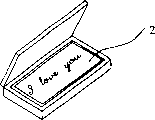
Figure 16 is that the present invention is applied in the synoptic diagram on the jewelry box;
Figure 17 is that the present invention is applied in the synoptic diagram on the technology drawing board;
Figure 18 is that the present invention is applied in the synoptic diagram on the accumulator tank;
Figure 19 is that the present invention is applied in the synoptic diagram on the greeting card;
Figure 20 is that the present invention is applied in the synoptic diagram on the Teddy bear;
Figure 21 is that the present invention is applied in the synoptic diagram on the alarm clock dial plate.
Embodiment
Embodiment describes in further detail the present invention below in conjunction with accompanying drawing.
Embodiment is 1.: as Fig. 1, Fig. 2, Fig. 4, Fig. 9, Figure 10, Figure 11, Figure 12, shown in Figure 13, it comprises light source 1, luminous plaque 2 and in order to produce voice and to control the bright dark control circuit 3 of light source, have the opening 4 that holds light source 1 in the side of luminous plaque 2, on the plane of luminous plaque 2, have a plurality of rectangular 5, shrinkage pool 5 is a clinoplane over against the plane of incidence 6 of light, angle theta 1 between the plane of itself and luminous plaque 2 is 25 degree, two sides of shrinkage pool 5 are vertical with the plane of luminous plaque 2, the light that light source 1 sends produces bright luminous point on the plane of incidence 5, the shape of shrinkage pool 5 also can be other different shape, the illumination effect of its generation is slightly poorer than rectangular, the degree of depth of shrinkage pool 5 can also can be penetrating less than the thickness of luminous plaque 2.
Light source 1 can be the light emitting diode of the high brightness of a plurality of different colours, in some specific application scenarios, also can use other higher source luminance, as when making the larger area billboard, even can also use laser to be used as light source.
Control circuit 3 is for can be to the programme voice IC chip 31 of light emitting control of multichannel light emitting diode, can design multiple voice, sound effect, music as required, the every triggering of trigger switch K that is connected input/output port once just can a kind of voice of conversion, sound effect, music, are connected with multichannel light emitting diode 11 and acoustical generator 32 on other input/output port of voice IC chip 31 respectively.
Embodiment is 2.: as Fig. 1, Fig. 2, Fig. 5, Fig. 9, Figure 10, Figure 11, Figure 12, shown in Figure 13, it comprises light source 1, luminous plaque 2 and in order to produce voice and to control the bright dark control circuit 3 of light source, have the opening 4 that holds light source 1 in the side of luminous plaque 2, on the plane of luminous plaque 2, have a plurality of rectangular 5, shrinkage pool 5 is a clinoplane over against the plane of incidence 6 of light, angle theta 2 between the plane of itself and luminous plaque 2 is 70 degree, two sides of shrinkage pool 5 are vertical with the plane of luminous plaque 2, the light that light source 1 sends produces bright luminous point on the plane of incidence 5, the shape of shrinkage pool 5 also can be other different shape, the illumination effect of its generation is slightly poorer than rectangular, the degree of depth of shrinkage pool 5 can also can be penetrating less than the thickness of luminous plaque 2.
Light source 1 can be the light emitting diode of the high brightness of a plurality of different colours, in some specific application scenarios, also can use other higher source luminance, as when making the larger area billboard, even can also use laser to be used as light source.
Control circuit 3 is for can be to the programme voice IC chip 31 of light emitting control of multichannel light emitting diode, can design multiple voice, sound effect, music as required, the every triggering of trigger switch K that is connected input/output port once just can a kind of voice of conversion, sound effect, music, are connected with multichannel light emitting diode 11 and acoustical generator 32 on other input/output port of voice IC chip 31 respectively.
Embodiment is 3.: as Fig. 1, Fig. 2, Fig. 6, Fig. 9, Figure 10, Figure 11, Figure 12, shown in Figure 13,1., 2. other structure all is same as embodiment, difference is between the plane of the plane of incidence 6 and luminous plaque 2 that it is 45 degree that angle is selected best angle θ 3, and this moment, emergent ray was perpendicular to the plane of luminous plaque 2.
As shown in Figure 7 and Figure 8, according to light refraction theorem: n
1Sin α=n
2Sin β, wherein, n
1And n
2Be the refractive index of luminous plaque and air, α and β are incident angle and refraction angle; When selecting to have suitable refractive index materials, owing to the total reflection effect that takes place on oblique incidence face makes the brightness of emergent ray the highest as luminous plaque; And in other cases, a part of light is by the reflection of oblique incidence face, and another part light is through having part light to be reflected again on other dip plane at shrinkage pool after the refraction of oblique incidence face, and its total brightness is slightly poorer than the situation of total reflection.
The invention has the advantages that the reflection and the refraction principle that have utilized traditional optical dexterously, leave the shrinkage pool of inclination at the diverse location of luminous plaque, make the light source that is arranged on the luminous plaque side on the oblique incidence face of shrinkage pool, produce bright luminous bright spot, light source is arranged on the diverse location of luminous plaque side, make its normal direction of light source of a certain relatively position of the plane of incidence of the shrinkage pool of forming same pattern identical, the output signal that is provided along with the voice IC of control circuit then, luminous plaque can present various pattern along with the rhythm of voice.The present invention has only just realized producing the purpose of various luminous patterns with a transparent plastic plate, and the light emitting diode that adopts high brightness is as light source, and not only volume is little, cost is low, and saves energy consumption, reliable operation, long service life has been widened its application greatly.From Figure 14, Figure 15, Figure 16, Figure 17, Figure 18, Figure 19, Figure 20, Figure 21 as can be seen, the present invention can be applied to various applications such as toy, gift, greeting card, ornaments, billboard.
Claims (10)
1, a kind of voice luminescence display panel, comprise light source (1) and luminous plaque (2) and in order to produce voice and to control the bright dark control circuit of light source (3), it is characterized in that: have the opening (4) that holds described light source (1) in the side of described luminous plaque (2), on the plane of described luminous plaque (2), have a plurality of shrinkage pools (5), described shrinkage pool (5) is the dip plane that is 25~70 degree angles with the plane of described luminous plaque (2) over against the plane of incidence (6) of light, and the light that described light source (1) sends is gone up at the described plane of incidence (6) and produced bright luminous point.
2, voice luminescence display panel as claimed in claim 1 is characterized in that: the shape of described shrinkage pool (5) is a rectangle, and the described plane of incidence (6) is the plane, and the described plane of incidence (6) is 45 degree with the angle on the plane of described luminous plaque (2).
3, voice luminescence display panel as claimed in claim 1 or 2 is characterized in that: the degree of depth of described shrinkage pool (5) is less than the thickness of described luminous plaque (2).
4, voice luminescence display panel as claimed in claim 3 is characterized in that: described light source (1) is the light emitting diode of the high brightness of a plurality of different colours.
5, voice luminescence display panel as claimed in claim 4, it is characterized in that: described control circuit (3) is for can be to the programme voice IC chip (31) of light emitting control of multichannel light emitting diode, its design has multiple voice, sound effect, music, and be connected with can the conversion voice, the trigger switch K of sound effect, music, be connected with light source (1) and acoustical generator (32) on each output terminal of described voice IC chip (31) respectively.
6, voice luminescence display panel as claimed in claim 5 is characterized in that: described luminous plaque (2) is a transparent plastic sheet.
7, voice luminescence display panel as claimed in claim 6, it is characterized in that: described luminous plaque (2) is a polygon, described light source (1) is separately positioned on the side on each bar limit of described luminous plaque (2), and the plane of incidence (6) of described shrinkage pool (5) is respectively over against the light source that is arranged on diverse location (1).
8, voice luminescence display panel as claimed in claim 6, it is characterized in that: described luminous plaque (2) is the flat circle arc, described light source (1) is separately positioned on the side of the circular arc limit diverse location of described luminous plaque (2), and the plane of incidence (6) of described shrinkage pool (5) is respectively over against the light source that is arranged on diverse location (1).
9, voice luminescence display panel as claimed in claim 7 is characterized in that: the normal direction of the plane of incidence (6) of forming the described shrinkage pool (5) of same pattern is identical.
10, voice luminescence display panel as claimed in claim 8 is characterized in that: the normal direction of the plane of incidence (6) of forming the described shrinkage pool (5) of same pattern is identical.
Priority Applications (1)
| Application Number | Priority Date | Filing Date | Title |
|---|---|---|---|
| CNB031149995A CN1182503C (en) | 2003-01-17 | 2003-01-17 | Speech active display plate |
Applications Claiming Priority (1)
| Application Number | Priority Date | Filing Date | Title |
|---|---|---|---|
| CNB031149995A CN1182503C (en) | 2003-01-17 | 2003-01-17 | Speech active display plate |
Publications (2)
| Publication Number | Publication Date |
|---|---|
| CN1431641A CN1431641A (en) | 2003-07-23 |
| CN1182503C true CN1182503C (en) | 2004-12-29 |
Family
ID=4790552
Family Applications (1)
| Application Number | Title | Priority Date | Filing Date |
|---|---|---|---|
| CNB031149995A Expired - Fee Related CN1182503C (en) | 2003-01-17 | 2003-01-17 | Speech active display plate |
Country Status (1)
| Country | Link |
|---|---|
| CN (1) | CN1182503C (en) |
Families Citing this family (1)
| Publication number | Priority date | Publication date | Assignee | Title |
|---|---|---|---|---|
| CN101469825B (en) * | 2007-12-26 | 2011-08-24 | 富士迈半导体精密工业(上海)有限公司 | Luminous panel |
-
2003
- 2003-01-17 CN CNB031149995A patent/CN1182503C/en not_active Expired - Fee Related
Also Published As
| Publication number | Publication date |
|---|---|
| CN1431641A (en) | 2003-07-23 |
Similar Documents
| Publication | Publication Date | Title |
|---|---|---|
| CN1252668C (en) | Lighting sources and luminescent panels | |
| CN1185510C (en) | Passive radiation light modules especially in combination with light-emitting diodes | |
| CN101089704B (en) | Light source apparatus and display apparatus | |
| CN1564923A (en) | Light-guide lights providing a substantially monochromatic beam | |
| CN103629570A (en) | lighting device | |
| US20090168458A1 (en) | Light-emitting panel and luminaire having same | |
| JP3326338B2 (en) | Luminescent sign board | |
| CN100529879C (en) | Straight down type back light module unit | |
| CN101769449A (en) | Thin lamp box | |
| CN2329062Y (en) | Displayer for light scattering plane | |
| CN2594812Y (en) | Light conducting panel and surface light source devices | |
| CN1182503C (en) | Speech active display plate | |
| JP3503608B2 (en) | Light point type display | |
| CN100370327C (en) | Backlight module | |
| CN101307881A (en) | Panel light source for back-lit signs | |
| CN220305511U (en) | Inverse prism composite brightness enhancement film and liquid crystal display backlight module | |
| CN210720801U (en) | Side light-entering type light guide plate and backlight module | |
| CN101383114B (en) | Advertisement board | |
| CN2786420Y (en) | LED traffic signal lamp | |
| CN209262771U (en) | A kind of OLED lamp piece and lamps and lanterns | |
| CN2668997Y (en) | Lighting device and light mixing assembly thereof | |
| CN2583755Y (en) | Light guide display device | |
| CN218886777U (en) | Structure of LED display screen | |
| CN223501517U (en) | Lens-type LED double-sided display screen | |
| CN2898591Y (en) | Light source module |
Legal Events
| Date | Code | Title | Description |
|---|---|---|---|
| C06 | Publication | ||
| PB01 | Publication | ||
| C10 | Entry into substantive examination | ||
| SE01 | Entry into force of request for substantive examination | ||
| C14 | Grant of patent or utility model | ||
| GR01 | Patent grant | ||
| C19 | Lapse of patent right due to non-payment of the annual fee | ||
| CF01 | Termination of patent right due to non-payment of annual fee |