CN1180373C - Data carrier having means for synchronizing with a received data stream - Google Patents
Data carrier having means for synchronizing with a received data stream Download PDFInfo
- Publication number
- CN1180373C CN1180373C CNB018011675A CN01801167A CN1180373C CN 1180373 C CN1180373 C CN 1180373C CN B018011675 A CNB018011675 A CN B018011675A CN 01801167 A CN01801167 A CN 01801167A CN 1180373 C CN1180373 C CN 1180373C
- Authority
- CN
- China
- Prior art keywords
- data
- delimiter
- useful
- useful data
- detection
- Prior art date
- Legal status (The legal status is an assumption and is not a legal conclusion. Google has not performed a legal analysis and makes no representation as to the accuracy of the status listed.)
- Expired - Lifetime
Links
Images

Classifications
-
- H—ELECTRICITY
- H04—ELECTRIC COMMUNICATION TECHNIQUE
- H04L—TRANSMISSION OF DIGITAL INFORMATION, e.g. TELEGRAPHIC COMMUNICATION
- H04L7/00—Arrangements for synchronising receiver with transmitter
- H04L7/04—Speed or phase control by synchronisation signals
- H04L7/041—Speed or phase control by synchronisation signals using special codes as synchronising signal
- H04L7/042—Detectors therefor, e.g. correlators, state machines
-
- G—PHYSICS
- G06—COMPUTING OR CALCULATING; COUNTING
- G06K—GRAPHICAL DATA READING; PRESENTATION OF DATA; RECORD CARRIERS; HANDLING RECORD CARRIERS
- G06K19/00—Record carriers for use with machines and with at least a part designed to carry digital markings
- G06K19/06—Record carriers for use with machines and with at least a part designed to carry digital markings characterised by the kind of the digital marking, e.g. shape, nature, code
- G06K19/067—Record carriers with conductive marks, printed circuits or semiconductor circuit elements, e.g. credit or identity cards also with resonating or responding marks without active components
- G06K19/07—Record carriers with conductive marks, printed circuits or semiconductor circuit elements, e.g. credit or identity cards also with resonating or responding marks without active components with integrated circuit chips
- G06K19/0723—Record carriers with conductive marks, printed circuits or semiconductor circuit elements, e.g. credit or identity cards also with resonating or responding marks without active components with integrated circuit chips the record carrier comprising an arrangement for non-contact communication, e.g. wireless communication circuits on transponder cards, non-contact smart cards or RFIDs
-
- G—PHYSICS
- G06—COMPUTING OR CALCULATING; COUNTING
- G06K—GRAPHICAL DATA READING; PRESENTATION OF DATA; RECORD CARRIERS; HANDLING RECORD CARRIERS
- G06K7/00—Methods or arrangements for sensing record carriers, e.g. for reading patterns
- G06K7/0008—General problems related to the reading of electronic memory record carriers, independent of its reading method, e.g. power transfer
Landscapes
- Engineering & Computer Science (AREA)
- Theoretical Computer Science (AREA)
- Computer Networks & Wireless Communication (AREA)
- Physics & Mathematics (AREA)
- General Physics & Mathematics (AREA)
- Microelectronics & Electronic Packaging (AREA)
- Computer Vision & Pattern Recognition (AREA)
- Computer Hardware Design (AREA)
- Artificial Intelligence (AREA)
- Signal Processing (AREA)
- Communication Control (AREA)
- Credit Cards Or The Like (AREA)
- Near-Field Transmission Systems (AREA)
- Synchronisation In Digital Transmission Systems (AREA)
- Signal Processing For Digital Recording And Reproducing (AREA)
- Mobile Radio Communication Systems (AREA)
- Maintenance And Management Of Digital Transmission (AREA)
Abstract
Description
技术领域technical field
本发明涉及一种具有电路的数据载体,其包括至少一个接口的若干部分,所述部分能够用于以数据块的形式接收数据,每个数据块包括定界符数据和有用数据,并且其包括定界符数据检测装置,它被提供来接收数据并且能够被用于检测一个第一数据块的定界符数据,并产生和提供至少一个有用数据开始信号,一旦检测到定界符数据,就可以产生并提供该至少一个有用数据开始信号,并且其包括数据测试装置,它被提供来接收数据并且能够被用于测试数据的数据差错。The invention relates to a data carrier with circuitry comprising at least one interface part capable of receiving data in the form of data blocks, each data block comprising delimiter data and useful data, and comprising Delimiter data detection means, which are provided to receive data and can be used to detect delimiter data of a first data block, and generate and provide at least one useful data start signal, once the delimiter data is detected, The at least one useful data start signal may be generated and provided and includes data testing means provided to receive data and which can be used to test the data for data errors.
本发明还涉及一种用于数据载体的电路,其包括至少一个接口的若干部分,所述部分能够用于以数据块的形式接收数据,每个数据块包括定界符数据和有用数据,并且其包括定界符数据检测装置,它被提供来接收数据并且能够用于检测一个第一数据块的定界符数据并产生和提供至少一个有用数据开始信号,一旦检测到定界符数据,就可以产生并提供该至少一个有用数据开始信号,并且其包括数据测试装置,它被提供来接收数据并且能够用于测试数据的数据差错。The invention also relates to a circuit for a data carrier, comprising parts of at least one interface, said parts being able to receive data in the form of data blocks, each data block comprising delimiter data and useful data, and It includes delimiter data detection means, which is provided to receive data and can be used to detect delimiter data of a first data block and generate and provide at least one useful data start signal, once the delimiter data is detected, The at least one useful data start signal may be generated and provided and includes data testing means provided to receive data and operable to test the data for data errors.
背景技术Background technique
本申请人已经开发出这样的数据载体和这样的电路并且已经将其作为名称为″I·CODE″之下的一个智能标志投放入市场并因此而知名。The applicant has developed such a data carrier and such a circuit and has placed it on the market as an intelligent label under the name "I·CODE" and is known as such.
已知的数据载体具有一个用于与一个有效的读写设备进行不接触通信的接口。当已知的数据载体出现在该有效的读写设备的通信范围之内时,在该读写设备和该数据载体之间建立一个电感耦合。然后,在接口的帮助下把用于数据载体的电路操作的功率提供给该数据载体,并在已经建立一个工作电压之后把一个电源开启复位信号应用到该电路。此外,数据载体在接口的帮助下接收数据流,所述数据采取数据块的形式。该数据块包括定界符数据和有用数据。The known data carrier has an interface for contactless communication with an active read/write device. When a known data carrier is present within the communication range of the active read/write device, an inductive coupling is established between the read/write device and the data carrier. Power for circuit operation of the data carrier is then supplied to the data carrier with the aid of the interface and a power-on reset signal is applied to the circuit after an operating voltage has been established. Furthermore, the data carrier receives a stream of data with the help of the interface, said data being in the form of data blocks. This data block includes delimiter data and useful data.
为了使有用数据能够被应用在数据载体中,应该首先使数据载体与接收数据流同步。为此目的,该数据载体包括数据载体定界符数据检测装置,其在激活状态下适合于检测定界符数据并且在这样一个检测之后提供一个有用数据开始信号。该定界符数据检测装置可以通过一个开始信号来激活,该开始信号是在该数据载体进入一个读写设备的通信范围之后的第一激活情况下由电源开启复位信号形成的。在定界符数据检测之后,有用数据开始信号被提供,这之后定界符数据检测装置是被去激活的。这结束了数据载体与接收数据的同步。In order for useful data to be available in the data carrier, the data carrier should first be synchronized with the received data stream. For this purpose, the data carrier comprises data carrier delimiter data detection means which, in an activated state, are adapted to detect delimiter data and to provide a useful data start signal after such a detection. The delimiter data detection device can be activated by a start signal formed by a power-on reset signal in the first activation situation after the data carrier has entered the communication range of a read-write device. After the delimiter data detection, the useful data start signal is provided, after which the delimiter data detection means are deactivated. This ends the synchronization of the data carrier with the received data.
可是,它还确定了同步已成功。为此目的,该数据载体具有一个适合于接收此有用数据开始信号的数据测试装置,用于在接收该有用数据开始信号之后测试接收数据的数据差错。该数据测试装置适合于在一个数据差错出现时提供一个数据差错信号。当在接收数据的测试过程中发现一个数据差错时,该数据测试装置产生并提供该数据差错信号,并且随后该数据测试装置被去激活。数据差错信号的出现可能有各种含义。一方面,它可能意味着一个传输差错已经出现或者包含在有用数据中的一个指令没有被提供。另一方面,数据差错信号的出现可能指出该数据载体与接收数据流没有正确同步。However, it also confirms that the synchronization was successful. For this purpose, the data carrier has a data testing device adapted to receive the useful data start signal for testing the received data for data errors after receiving the useful data start signal. The data testing device is adapted to provide a data error signal when a data error occurs. When a data error is found during the test of received data, the data test device generates and provides the data error signal, and then the data test device is deactivated. The occurrence of a data error signal can have various meanings. On the one hand, it may mean that a transmission error has occurred or that a command contained in the useful data was not delivered. On the other hand, the presence of a data error signal may indicate that the data carrier is not correctly synchronized with the received data stream.
在目前的情况中,数据差错信号形成定界符数据检测装置的开始信号而不管该数据差错信号的含意,其结果是:该定界符数据检测装置被重新激活并再一次开始定界符数据的一个检测。因此,数据载体的同步被重新启动。In the present case, the data error signal forms the start signal of the delimiter data detection means regardless of the meaning of the data error signal, with the result that the delimiter data detection means is reactivated and starts the delimiter data again a detection of . Accordingly, the synchronization of the data carriers is restarted.
在已知的数据载体的情况中,数据载体的重新同步(其仍然是在通信范围之内)被重复直到该数据测试装置不再检测到任何数据差错为止。当如下情形出现时,即,当数据差错信号不出现时,该数据测试装置适合于提供有用数据给一个有用数据处理装置,在此之后数据测试装置被去激活。In the case of the known data carrier, the resynchronization of the data carrier, which is still within the communication range, is repeated until the data testing device no longer detects any data errors. The data test device is adapted to supply useful data to a useful data processing device when the following situation occurs, ie when the data error signal is not present, after which the data test device is deactivated.
当在一个通信协议(其定义了数据流的时序和定界符数据的内容和数据块的有用数据)中,采取适当的措施,例如在定界符数据和有用数据之间的一个明确的区别时,即,当要被传送的有用数据之通信协议的独立性被保证时,已知的数据载体与数据流的一个简单可靠的同步在想象为数据载体所使用而可接受的一个可预测时间间隔之内是可能的。When in a communication protocol (which defines the timing of the data stream and the content of the delimiter data and the useful data of the data block), take appropriate measures, such as a clear distinction between the delimiter data and the useful data time, that is, when the independence of the communication protocol of the useful data to be transferred is guaranteed, a simple and reliable synchronization of the known data carrier with the data stream at a predictable time imagined to be acceptable for use by the data carrier within the interval is possible.
即使在定界符数据和有用数据之间没有明确区别的情况下,即通信不独立于要被传送的有用数据时,在数据块之间的一个比有用数据的脉冲之间最大脉冲间隔更长的数据块中止的供应也能够达到一个可靠的同步,但是这样的代价是一个不期望的通信时间延长。Even in cases where there is no clear distinction between delimiter data and useful data, i.e. when the communication is not independent of the useful data to be transmitted, a maximum pulse interval between data blocks is longer than between pulses of useful data An aborted supply of data blocks can also achieve a reliable synchronization, but this comes at the cost of an undesired prolongation of the communication time.
当已知的数据载体使用按照通信标准ISO/IEG FDIS 15693-2:1999(E)的通信协议时,数据载体与数据流的同步中的问题可能出现,因为这个通信协议不保证有用数据的通信协议的独立。这是因为所述标准在一个数据块的开始处(SOF定界符数据)和一个数据块的结束处(EOF定界符数据)提供不同的定界符数据,EOF定界符数据形成SOF定界符数据的一个子组。与这个通信协议有关可能出现这样的问题:利用已知的数据载体和已知电路,与EOF定界符数据相邻的有用数据部分和EOF定界符数据部分的一个组合被错误地检测为SOF定界符数据,在此之后定界符数据检测装置错误地使数据测试装置开始一个测试,其测试不可避免地以一个新的同步处理而结束。对于按照在前提及的标准的两种不同的数据编码,可以出现至少65种组合,对于在最坏情况下,甚至没有可能与接收数据流同步。Problems in the synchronization of the data carrier with the data stream may arise when the known data carrier uses a communication protocol according to the communication standard ISO/IEG FDIS 15693-2:1999(E), since this communication protocol does not guarantee the communication of useful data Protocol Independence. This is because the standard provides different delimiter data at the beginning of a data block (SOF delimiter data) and at the end of a data block (EOF delimiter data), and the EOF delimiter data forms the SOF delimiter data. A subgroup of delimiter data. The problem may arise in relation to this communication protocol that, with known data carriers and known circuits, a combination of a useful data part adjacent to an EOF delimiter data and an EOF delimiter data part is erroneously detected as SOF Delimiter data, after which the delimiter data detection means erroneously causes the data test means to start a test which inevitably ends with a new synchronization process. For two different data encodings according to the aforementioned standard, at least 65 combinations are possible, and in the worst case, it is not even possible to synchronize with the received data stream.
发明内容Contents of the invention
本发明的一个目的是利用本发明第一个技术方案的一个数据载体以及利用本发明第十四个技术方案的数据载体的一个电路来排除在前提及的问题并且提供一种改良的数据载体和该数据载体的一种改良的电路,利用它,即使在通信协议不独立于有用数据的情况下,也可确保数据载体和数据载体的电路中的接收数据流的一个可靠同步。An object of the present invention is to eliminate the aforementioned problems and provide an improved data carrier and An improved circuit of the data carrier with which a reliable synchronization of the data carrier and the received data stream in the circuit of the data carrier is ensured even if the communication protocol is not independent of the useful data.
根据本发明的第一个方案,提供了一种具有电路的数据载体,其包括至少一个接口的若干部分,所述部分能够用于以数据块的形式接收数据,每个数据块包括定界符数据和有用数据,并且其包括定界符数据检测装置,它被提供来接收数据并且能够被用于检测一个第一数据块的定界符数据,并产生和提供至少一个有用数据开始信号,一旦检测到定界符数据,就可以产生并提供该至少一个有用数据开始信号,并且其包括数据测试装置,它被提供来接收数据并且能够被用于测试数据的数据差错,其特征在于:该定界符数据检测装置能够用于在接收到由先前提供的有用数据开始信号所指示的有用数据期间不断地重新检测一个第二数据块的定界符数据,并且还在先前提供有用数据开始信号之后产生并提供有用数据开始信号。According to a first aspect of the invention, there is provided a data carrier with circuitry comprising at least one interface parts capable of receiving data in the form of data blocks, each data block comprising a delimiter data and useful data, and it includes delimiter data detection means, which is provided to receive data and can be used to detect the delimiter data of a first data block, and generate and provide at least one useful data start signal, once Detecting delimiter data, just can generate and provide this at least one useful data start signal, and it comprises data testing device, and it is provided to receive data and can be used for the data error of test data, it is characterized in that: The delimiter data detection means can be used for continuously re-detecting the delimiter data of a second data block during the reception of the useful data indicated by the previously provided useful data start signal, and also after the previously provided useful data start signal Generate and provide a useful data start signal.
根据本发明的第十四个方案,提供了一种用于数据载体的电路,其包括至少一个接口的若干部分,所述部分能够用于以数据块的形式接收数据,每个数据块包括定界符数据和有用数据,并且其包括定界符数据检测装置,它被提供来接收数据并且能够用于检测一个第一数据块的定界符数据并产生和提供至少一个有用数据开始信号,一旦检测到定界符数据,就可以产生并提供该至少一个有用数据开始信号,并且其包括数据测试装置,它被提供来接收数据并且能够用于测试数据的数据差错,其特征在于:该定界符数据检测装置能够用于在接收到由先前提供的有用数据开始信号所指示的用户数据期间不断地重新检测一个第二数据块的定界符数据并且还在先前提供有用数据开始信号之后产生并提供有用数据开始信号。According to a fourteenth aspect of the present invention, there is provided a circuit for a data carrier comprising parts of at least one interface, said parts being capable of receiving data in the form of data blocks, each data block comprising defined Delimiter data and useful data, and it comprises delimiter data detecting means, it is provided to receive data and can be used for detecting the delimiter data of a first data block and generating and providing at least one useful data start signal, once Detect delimiter data, just can generate and provide this at least one useful data start signal, and it comprises data testing device, it is provided to receive data and can be used for the data error of test data, it is characterized in that: The delimiter data detecting means can be used for constantly re-detecting the delimiter data of a second data block during receiving user data indicated by the previously provided useful data start signal and also generating and Provides useful data start signal.
分别利用上述第一种和第十四种技术方案,以一种有利的方式来达到:即使在通信协议不独立于有用数据的情况下也保证与数据载体和数据载体的电路中的接收数据流的一个可靠同步。With the above-mentioned first and fourteenth technical solutions respectively, it is achieved in an advantageous manner that the received data flow with the data carrier and in the circuit of the data carrier is guaranteed even if the communication protocol is not independent of the useful data A reliable synchronization of .
根据本发明的第二种技术方案,在第一种技术方案中,判决装置被提供,在利用数据测试装置进行测试期间,能够用于根据至少一个判定准则来判决定界符数据的重新检测是否可以被终止,并且在满足判定准则之后,定界符数据检测装置能够用于终止定界符数据的检测。According to the second technical solution of the present invention, in the first technical solution, judging means are provided, which can be used to judge whether the re-detection of the delimiter data is can be terminated, and the delimiter data detection means can be used to terminate the detection of the delimiter data after satisfying a decision criterion.
根据本发明的第十五种技术方案,在第十四种技术方案中,判决装置被提供,在利用数据测试装置进行测试期间,该判决装置能够用于根据至少一个判定准则来判决定界符数据的重新检测是否可以被终止,并且在满足判定准则之后,定界符数据检测装置能够用于终止定界符数据的检测。According to the fifteenth technical solution of the present invention, in the fourteenth technical solution, a judging device is provided, which can be used to judge the delimiter according to at least one judging criterion during the test with the data testing device. Whether the re-detection of data can be terminated, and after satisfying the decision criteria, the delimiter data detection means can be used to terminate the detection of delimiter data.
分别利用上述第二种和第十五种技术方案,以一种有利的方式来达到:在定界符数据的检测和有用数据的测试开始之后,当已经确定一个数据块的有效定界符数据已经被检测到时,则可以终止定界符数据不断重复的检测。还可获得另外一个优点,即,在已经确定一个数据块的有效定界符数据已经被检测之后,避免了定界符数据不必要的不断重复检测,这确保不会错误地中断在定界符可能的重新检测的情况下数据块的有用数据的测试。Utilize the above-mentioned second and fifteenth technical solutions respectively to achieve in an advantageous manner: after the detection of the delimiter data and the testing of the useful data start, when the effective delimiter data of a data block has been determined When it has been detected, the repeated detection of the delimiter data can be terminated. An additional advantage is obtained in that, after it has been determined that valid delimiter data for a data block has been detected, unnecessarily repeated detection of delimiter data is avoided, which ensures that no erroneously interrupted A test of the useful data of a data block in case of possible re-detection.
根据本发明的第三种技术方案,在第二种技术方案中,定界符数据计数装置被提供,能够用于对重新检测的定界符数据进行计数并提供一个定界符数据计数,此定界符数据计数表示多个被计数的重新检测的定界符数据,并且该判决准则通过由数″1″表示的定界符数据计数来形成。According to the third technical solution of the present invention, in the second technical solution, the delimiter data counting device is provided, which can be used to count the delimiter data re-detected and provide a delimiter data count, which The delimiter data count represents a number of counted re-detected delimiter data, and the decision criterion is formed by the delimiter data count represented by the number "1".
根据本发明的第十六种技术方案,在第十五种技术方案中,有用数据时间测量装置被提供,当有用数据脉冲计数由数″1″表示时,该有用数据时间测量装置能够用于测量一个有用数据时间间隔并产生一个有用数据时间测量数值,此有用数据时间测量数值表示测量的有用数据时间间隔,并且第二判定准则通过由数″1″表示的有用数据脉冲计数和通过有用数据时间测量数值来形成,该有用数据时间测量数值表示测量的有用数据时间间隔并且它对应于表示定界符数据的接收的一个时间间隔。According to the sixteenth technical solution of the present invention, in the fifteenth technical solution, a useful data time measuring device is provided, and when the useful data pulse count is represented by the number "1", the useful data time measuring device can be used for A useful data time interval is measured and a useful data time measurement value is generated, this useful data time measurement value represents the measured useful data time interval, and the second decision criterion is counted by the useful data pulse represented by the number "1" and passed by the useful data time interval A time measurement value is formed which represents the measured useful data time interval and which corresponds to a time interval representing the reception of the delimiter data.
分别利用上述第三种和第十六种技术方案,以一种有利的方式来达到:早已在定界符数据的检测和定界符数据的第一个重新检测之后,定界符数据不断重复的检测被中止,因为在第一个重新检测之后没多久有效定界符数据应该是有效的,并且因此,一个不断重复的检测是无意义的。还可获得另外一个优点,即一个重新检测可以被简单地比较地识别,因为这只需要提供用于对检测的定界符数据进行计数的装置。Using the above-mentioned third and sixteenth technical solutions respectively, it is achieved in an advantageous manner that already after the detection of the delimiter data and the first re-detection of the delimiter data, the delimiter data is constantly repeated The test is aborted because valid delimiter data should be valid not long after the first retest, and therefore, an endlessly repeated test is pointless. A further advantage is also obtained that a re-detection can be identified comparatively simply, since it is only necessary to provide means for counting the detected delimiter data.
根据本发明的第四种技术方案,在第三种技术方案中,判决装置形成定界符数据检测装置的若干部分。According to the fourth technical solution of the present invention, in the third technical solution, the judging means forms several parts of the delimiter data detecting means.
根据本发明的第十七种技术方案,在第十六种技术方案中,判决装置形成定界符数据检测装置的若干部分。According to the seventeenth technical solution of the present invention, in the sixteenth technical solution, the judging means forms several parts of the delimiter data detecting means.
分别利用上述第四种技术方案和第十七种技术方案,以一种有利的方式来达到:定界符数据检测装置可以独立地判决有关定界符数据的重新检测。Using the above-mentioned fourth technical solution and the seventeenth technical solution respectively, it is achieved in an advantageous manner: the delimiter data detection device can independently judge the re-detection of the delimiter data.
根据本发明的第五种技术方案,在第二种技术方案中,有用数据脉冲计数装置被提供,能够用于对包括在有用数据中的脉冲进行计数并提供一个有用数据脉冲计数,此有用数据脉冲计数表示若干被计数的脉冲,并且第一判定准则通过由数″2″表示的有用数据脉冲计数来形成。According to a fifth technical solution of the present invention, in the second technical solution, useful data pulse counting means are provided, capable of counting pulses included in useful data and providing a useful data pulse count, the useful data The pulse count represents a number of counted pulses, and the first decision criterion is formed by the useful data pulse count represented by the number "2".
根据本发明的第十八种技术方案,在第十五种技术方案中,有用数据脉冲计数装置被提供,其能够用于对包括在有用数据中的脉冲进行计数并提供一个有用数据脉冲计数,此有用数据脉冲计数表示若干被计数的脉冲,并且第一判定准则通过由数″2″表示的有用数据脉冲计数来形成。According to the eighteenth technical solution of the present invention, in the fifteenth technical solution, a useful data pulse counting device is provided, which can be used to count the pulses included in the useful data and provide a useful data pulse count, This useful data pulse count represents a number of counted pulses, and the first decision criterion is formed by the useful data pulse count represented by the number "2".
分别利用上述第五种和第十八种技术方案,以一种有利的方式来达到:如果在第二脉冲出现期间,在定界符数据检测装置的帮助下没有检测到有效的定界符数据,则在有用数据中出现的第二个脉冲之后,定界符数据不断重复的检测可能已经被中止,因为在这种情况下,第一个脉冲和第二个脉冲已经形成数据块的有用数据部分。Respectively using the above-mentioned fifth and eighteenth technical solutions, it is achieved in an advantageous manner: if no valid delimiter data is detected with the help of the delimiter data detection means during the occurrence of the second pulse , then after the second pulse occurring in the useful data, the detection of the constant repetition of the delimiter data may have been aborted, since in this case the first pulse and the second pulse already form the useful data of the data block part.
根据本发明的第六种技术方案,在第五种技术方案中,有用数据时间测量装置被提供,当有用数据脉冲计数(W)由数″1″表示时,该有用数据时间测量装置能够用于测量一个有用数据时间间隔并产生一个有用数据时间测量数值,此有用数据时间测量数值表示测量的有用数据时间间隔,并且第二判定准则通过由数″1″表示的有用数据脉冲计数和通过有用数据时间测量数值来形成,该有用数据时间测量数值表示测量的有用数据时间间隔并且它对应于表示定界符数据的接收的一个时间间隔。According to the sixth technical solution of the present invention, in the fifth technical solution, the useful data time measuring device is provided, and when the useful data pulse count (W) is represented by the number "1", the useful data time measuring device can use For measuring a useful data time interval and generating a useful data time measurement value, this useful data time measurement value represents the measured useful data time interval, and the second decision criterion is counted by the useful data pulse represented by the number "1" and passed the useful data time interval A data time measurement value is formed which represents the measured useful data time interval and which corresponds to a time interval representing the reception of the delimiter data.
根据本发明的第十九种技术方案,在第十八种技术方案中,有用数据时间测量装置被提供,当有用数据脉冲计数(W)由数″1″表示时,该有用时间测量装置能够用于测量一个有用数据时间间隔并产生一个有用数据时间测量数值,此有用数据时间测量数值表示测量的有用数据时间间隔,并且第二判定准则(V2)通过由数″1″表示的有用数据脉冲计数(W)和通过有用数据时间测量数值来形成,该有用数据时间测量数值表示测量的有用数据时间间隔并且它对应于表示定界符数据(SD)的接收的一个时间间隔。According to the nineteenth technical solution of the present invention, in the eighteenth technical solution, the useful data time measuring device is provided, and when the useful data pulse count (W) is represented by the number "1", the useful time measuring device can For measuring a useful data time interval and generating a useful data time measurement value, this useful data time measurement value represents the measured useful data time interval, and the second decision criterion (V2) passes the useful data pulse represented by the number "1" The count (W) is formed by a useful data time measurement value representing the measured useful data time interval and which corresponds to a time interval representing the reception of delimiter data (SD).
分别利用上述第六种和第十九种技术方案,以一种有利的方式来达到:在有用数据中出现的第一个脉冲之后以及紧接着在第一个脉冲出现之后测量的时间间隔(该时间间隔对应用于表示接收定界符数据的一个时间间隔)满期后,定界符数据不断重复的检测可能已经被中止,因为在这种情况下,第一个脉冲已经形成数据块的有用数据部分。Utilize above-mentioned 6th and 19th technical solutions respectively, reach in a kind of advantageous manner: the time interval (the Time interval corresponds to a time interval used to indicate the receipt of delimiter data) After the expiration of the delimiter data repeated detection may have been aborted, because in this case, the first pulse has formed a useful data block data part.
根据本发明的第七种技术方案,在第六种技术方案中,利用定界符数据检测装置的若干部分来形成判决装置。According to the seventh technical solution of the present invention, in the sixth technical solution, several parts of the delimiter data detection device are used to form the judging device.
根据本发明的第二十种技术方案,在第十九种技术方案中,利用定界符数据检测装置的多个部分来形成判决装置。According to the twentieth technical solution of the present invention, in the nineteenth technical solution, a plurality of parts of the delimiter data detection device are used to form the judging device.
分别利用第七种和第二十种技术方案,以一种有利的方式来达到:使用定界符数据检测装置中已经存在的部分以最简单的可能方式来实现该判决装置。With the seventh and twentieth technical solutions respectively, it is achieved in an advantageous manner that the decision means is implemented in the simplest possible way using already existing parts of the delimiter data detection means.
根据本发明的第八种技术方案,在第一种技术方案中,数据测试装置的启动禁止装置被提供,此禁止装置能够用于接收可以由数据测试装置提供的一个数据差错信号,该数据差错信号使一个数据差错能够在数据的数据差错测试期间被发出,并且如果没有该数据差错信号时能够用于禁止利用数据测试装置来启动数据的数据差错测试。According to the eighth technical solution of the present invention, in the first technical solution, the activation prohibiting device of the data testing device is provided, and this prohibiting device can be used to receive a data error signal that can be provided by the data testing device, the data error The signal enables a data error to be signaled during data error testing of the data and, in the absence of the data error signal, can be used to disable the use of the data testing means to initiate data error testing of the data.
根据本发明的第二十一种技术方案,在第十四种技术方案中,数据测试装置的启动禁止装置被提供,此禁止装置能够用于接收可以由数据测试装置提供的一个数据差错信号,该数据差错信号使一个数据差错能够在数据的数据差错测试期间被发出,并且如果没有该数据差错信号时能够用于利用数据测试装置来启动数据的数据差错测试。According to the twenty-first technical solution of the present invention, in the fourteenth technical solution, the start prohibiting device of the data testing device is provided, and this prohibiting device can be used to receive a data error signal that can be provided by the data testing device, The data error signal enables a data error to be signaled during data error testing of the data and, in the absence of the data error signal, can be used to initiate data error testing of the data using the data testing means.
分别利用上述第八种和第二十一种技术方案,以一种有利的方式来达到:当报告没有数据差错时,则在测试数据的数据差错期间,紧接着有用数据中定界符数据的检测之后,数据测试装置所不希望的新的并因此是错误的开始被排除。Respectively utilize the eighth and twenty-first technical solutions above to achieve in an advantageous manner: when there is no data error in the report, then during the data error period of the test data, immediately after the delimiter data in the useful data After detection, undesired new and therefore erroneous starts of the data testing device are eliminated.
根据本发明的第九种技术方案,在第八种技术方案中,该启动禁止装置被利用电源禁止装置来形成,该电源禁止装置能够用于在没有数据差错信号的情况下禁止在测试之后可以被直接提供的一个有用数据开始信号。According to the ninth technical solution of the present invention, in the eighth technical solution, the start-up inhibiting means is formed by using a power supply inhibiting means which can be used to disable the A useful data start signal is provided directly.
根据本发明的第二十二种技术方案,在第二十一种技术方案中,该启动禁止装置被利用电源禁止装置来形成,该电源禁止装置能够用于在没有数据差错信号的情况下禁止在测试之后可以被直接提供的一个有用数据开始信号。According to the 22nd technical solution of the present invention, in the 21st technical solution, the start-up prohibiting device is formed by using a power supply prohibiting device, which can be used to disable A useful data start signal that can be provided directly after the test.
分别利用上述第九种和第二十二种技术方案,以一种有利的方式来达到:通过禁止提供有用数据开始信号(用于启动测试数据的数据差错)来避免数据测试装置的错误启动。Using the above-mentioned ninth and twenty-second technical solutions respectively, it is achieved in an advantageous manner: by prohibiting the provision of the useful data start signal (data error for starting the test data) to avoid false start of the data testing device.
分别作为提供如权利要求10和权利要求23所定义的那些特性特征的结果,以一种有利的方式来达到:例如,在定界符数据检测装置的可控制输出(此输出被有利地配置,使得本质上可通过数据差错信号直接地控制)的帮助下,可简单地禁止有用数据开始信号(用于启动测试数据的数据差错)的提供。As a result of providing those characteristic features as defined in
根据本发明的第十一种技术方案,在第八种技术方案中,该启动禁止装置被利用接收禁止装置来形成,该接收禁止装置能够用于在没有数据差错信号的情况下禁止在测试之后可以被直接接收的一个有用数据开始信号。According to the eleventh technical solution of the present invention, in the eighth technical solution, the start-up inhibiting means is formed by receiving inhibiting means, and the receiving inhibiting means can be used to disable after-test A useful data start signal that can be received directly.
根据本发明的第二十四种技术方案,在第十四种技术方案中,该启动禁止装置被利用接收禁止装置来形成,该接收禁止装置能够用于在没有数据差错信号的情况下禁止在测试之后可以被直接接收的一个有用数据开始信号。According to the twenty-fourth technical solution of the present invention, in the fourteenth technical solution, the activation prohibiting means is formed by a receiving prohibiting device, which can be used to prohibit A useful data start signal that can be received directly after the test.
分别利用上述第十一种和第二十四种技术方案,以一种有利的方式来达到:通过禁止接收有用数据开始信号(用于启动测试数据的数据差错)的数据测试装置的错误启动。Using the above-mentioned eleventh and twenty-fourth technical solutions respectively, it is achieved in an advantageous manner: by prohibiting false start of the data testing device receiving the useful data start signal (data error for starting test data).
根据本发明的第十二种技术方案,在第八种技术方案中,启动禁止装置形成数据测试装置的若干部分。According to the twelfth technical solution of the present invention, in the eighth technical solution, the activation prohibiting device forms several parts of the data testing device.
根据本发明的第二十五种技术方案,在第二十一种技术方案中,启动禁止装置形成数据测试装置的若干部分。According to the twenty-fifth technical solution of the present invention, in the twenty-first technical solution, the activation prohibiting device forms several parts of the data testing device.
分别利用上述第十二种和第二十五种技术方案,以一种有利的方式来达到:例如,在数据测试装置的可控制输入(此输入被有利地配置使得本质上可通过数据差错信号直接地控制)的帮助下,可简单地完成对有用数据开始信号(用于启动测试数据的数据差错)接收的禁止。Respectively using the above-mentioned twelfth and twenty-fifth technical solutions, it is achieved in an advantageous manner: for example, at the controllable input of the data testing device (this input is advantageously configured so that the data error signal can be passed essentially Inhibiting the reception of the useful data start signal (data error for starting test data) can be done simply with the help of direct control).
根据本发明的第十三种技术方案,在第一种技术方案中,电路采取集成电路的形式。According to the thirteenth technical solution of the present invention, in the first technical solution, the circuit takes the form of an integrated circuit.
根据本发明的第二十六种技术方案,在第十四种技术方案中,电路采取集成电路的形式。According to the twenty-sixth technical solution of the present invention, in the fourteenth technical solution, the circuit takes the form of an integrated circuit.
分别利用上述第十三种和第二十六种技术方案,以一种有利的方式来达到:在适当大生产量的情况下,保证了以最低可能成本的生产。By utilizing the above-mentioned thirteenth and twenty-sixth technical solutions respectively, it is achieved in an advantageous manner: in the case of a moderately large production volume, the production at the lowest possible cost is guaranteed.
通过例子从下文中描述的实施例中,本发明的上述以及另外的方面将变得显而易见,并且将参考这些例子来说明。These and further aspects of the invention will be apparent from and elucidated with reference to the embodiments described hereinafter.
附图说明Description of drawings
现在将参考附图更详细地描述本发明,附图示出了通过例子给出的一些实施例,但是本发明不被限制为此。The invention will now be described in more detail with reference to the accompanying drawings, which show some embodiments given by way of example, but to which the invention is not limited.
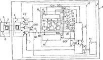
图1以方框图的形式图示出本发明第一实施例中的数据载体和数据载体的电路的相关部分。Figure 1 illustrates, in block diagram form, a data carrier and relevant parts of the circuitry of the data carrier in a first embodiment of the invention.
图2以类似于图1的方式示出了本发明第二实施例中的数据载体和数据载体的电路。FIG. 2 shows, in a similar manner to FIG. 1 , a data carrier and an electrical circuit of the data carrier in a second embodiment of the invention.
图3以类似于图1的方式示出了本发明第三实施例中的数据载体和数据载体的电路。FIG. 3 shows, in a similar manner to FIG. 1 , a data carrier and an electrical circuit of the data carrier in a third embodiment of the invention.
图4以类似于图1的方式示出了本发明第四实施例中的数据载体和数据载体的电路。FIG. 4 shows, in a similar manner to FIG. 1 , a data carrier and an electrical circuit of the data carrier in a fourth embodiment of the invention.
图5以类似于图1的方式示出了本发明第五实施例中的数据载体和数据载体的电路。FIG. 5 shows, in a similar manner to FIG. 1 , a data carrier and an electrical circuit of the data carrier in a fifth embodiment of the invention.
图6以类似于图1的方式示出了本发明第六实施例中的数据载体和数据载体的电路。FIG. 6 shows, in a similar manner to FIG. 1 , a data carrier and an electrical circuit of the data carrier in a sixth embodiment of the invention.
具体实施方式Detailed ways
图1表示一个读写设备1的方框图,其服务并且适合于按照标准ISO/IEC FDIS 15693-2:1999(E)的一个通信协议来提供数据D的双向通信,即从数据载体接收数据D并向数据载体发射数据D,在下文中不解释接收因为它与本发明不相关。Figure 1 shows a block diagram of a read-write device 1, which serves and is adapted to provide bidirectional communication of data D according to a communication protocol of standard ISO/IEC FDIS 15693-2:1999 (E), i.e. receiving data D from a data carrier and Transmission of data D to the data carrier, reception is not explained below as it is not relevant to the invention.
为了发射的目的,读写设备1具有设备接口装置2。设备接口装置2包括一个第一通信线圈3,可以在图1中未示出的装置的帮助下利用一个高频率载波信号来激励此通信线圈3。在数据D的发射期间,通过图1中未示出的调制装置按照数据D来对载波信号进行幅度调制。For transmission purposes, the read/write device 1 has a
把要被发射的数据作为一个数据流D来发射,此数据流采取具有插入间隔的数据块的形式,每个数据块包括定界符数据SD和ED和有用数据UD,此有用数据UD被安排在定界符数据SD和ED之间。按照标准,在有用数据UD前的定界符数据SD(所谓的SOF定界符数据SD),可以与有用数据UD后面的定界符数据ED(所谓的EOF定界符数据ED)相区分,EOF定界符数据ED形成SOF定界符数据SD的一个子组。按照标准,有用数据UD可以包含除了其它的之外的指令和信息。The data to be transmitted is transmitted as a data stream D, which takes the form of data blocks with intervening intervals, each data block comprising delimiter data SD and ED and useful data UD, the useful data UD being arranged Between the delimiter data SD and ED. According to the standard, the delimiter data SD preceding the useful data UD (so-called SOF delimiter data SD) can be distinguished from the delimiter data ED following the useful data UD (so-called EOF delimiter data ED), The EOF delimiter data ED form a subset of the SOF delimiter data SD. According to the standard, the user data UD can contain, among other things, instructions and information.
图1还示出了数据载体4的方框图,其适合于向读写设备1提供数据D的无接点双向通信。为此目的,数据载体具有一个电路5,此电路5包括至少一个接口6的电路部分,该电路部分既适合于以数据块的形式接收数据D又适合于以数据块的形式发射数据D。FIG. 1 also shows a block diagram of a
接口6包括第二通信线圈7和数据转换装置8和一个电压发生器9以及时钟发生装置9A。在目前的情况中,通过时钟发生装置9A、电压发生器9和数据转换装置8来形成该至少一个接口6的电路部分。接口6的电路部分适合于由第二通信线圈7来激励。The
以这样的一种方式配置接口6,即,在把数据载体4引入读写设备1的通信范围中之后,可以在第一通信线圈3和第二通信线圈7之间建立一个电感耦合。当该电感耦合存在于第一通信线圈3和第二通信线圈7之间时,可以把功率从读写设备1中发射给数据载体4,并且,在接口6的帮助下,读写设备1和数据载体4之间的数据D的通信是可能的。接口6首先为电路5启动一个由电压发生器9产生的电源电压V。同时时钟发生装置9A为电路5的数据处理装置10启动一个从接收的载波信号中得到的系统时钟CLK,并且将其提供给数据处理装置10。当系统时钟CLK稳定并且电源电压V已经达到它的标称值时,电压发生器9可以提供一个电源开启复位信号POR给数据处理装置。从而,启动数据处理装置10中开始的数据处理。数据转换装置8被按照这样的一种方式来配置,即,它们适合于在从读写设备1发射数据D到数据载体4期间,从第二通信线圈7中接收已调载波信号。数据转换装置可以把接收的已调载波信号转换为数据的串行数字表示,并且数据转换装置8可以把这些提供给数据处理装置10。在从数据载体4发射数据D到读写设备1期间,数据转换装置8适合于从数据处理装置10接收数据D。在这种情况下,数据转换装置8适合于完成通过通信线圈7接收的载波信号的负载调制,因此使数据D能够从数据载体4发射到读写设备1。The
除了接口6的电路部分之外,电路5包括定界符数据检测装置11、数据测试装置12、有用数据处理装置13和存储器装置14。当数据转换装置8提供数据D给数据处理装置10时,该数据可以被应用到定界符数据检测装置11。定界符数据检测装置11适合于检测数据决的定界符数据SD和ED,并且紧接着SOF定界符数据SD的检测,提供一个有用数据开始信号SOF,此有用数据开始信号SOF可以紧接着定界符数据SD的检测之后被产生和提供。当电源开启复位信号POR发生时,定界符数据检测装置11可以重新启动检测。In addition to the circuit parts of the
定界符数据检测装置11包括有用数据开始检测装置15,用于检测包括在数据D中的有用数据的一个有用数据开始。有用数据开始检测装置15因此适合于检测SOF定界符数据SD,并且,紧接着SOF定界符数据SD检测之后,产生并提供有用数据开始信号SOF。The delimiter data detection means 11 comprise useful data start detection means 15 for detecting a useful data start of the useful data contained in the data D. FIG. The start of useful data detection means 15 is thus adapted to detect the SOF delimiter data SD and, immediately after detection of the SOF delimiter data SD, generate and provide the start of useful data signal SOF.
在目前的情况中,有用数据开始检测装置15还适合于在SOF定界符数据SD的检测期间检测数据D的编码类型。在目前的情况中,可以检测第一编码类型和第二编码类型。当检测到第一编码类型时,有用数据开始检测装置15适合于产生并提供第一编码信息CI1给数据测试装置12。In the present case, the start of useful data detection means 15 is also adapted to detect the encoding type of the data D during the detection of the SOF delimiter data SD. In the present case, a first encoding type and a second encoding type can be detected. When the first encoding type is detected, the useful data start detection means 15 are adapted to generate and provide the first encoding information CI1 to the data testing means 12 .
定界符数据检测装置11还适合于接收一个数据差错信号DE,响应于此数据差错信号DE的接收,可以在数据D中开始一个SOF定界符数据SD的新检测。The delimiter data detection means 11 are also adapted to receive a data error signal DE, in response to the receipt of which data error signal DE, a new detection of SOF delimiter data SD in the data D can be started.
而且,定界符数据检测装置11适合于接收一个准备接收信号R(ready-to-receive signal),一旦接收到准备接收信号R,定界符数据检测装置11就可以重新开始定界符数据SD和ED的检测。And, the delimiter
定界符数据检测装置11还包括有用数据结束检测装置16,用于检测包括在数据D中的有用数据UD的一个有用数据结束。有用数据结束检测装置16因此适合于检测EOF定界符数据ED,并且紧接着EOF定界符数据ED的检测之后,产生并提供该有用数据结束信号EOF。有用数据结束检测装置16还适合于接收有用数据开始信号SOF,以便当收到有用数据开始信号SOF时能够启动EOF定界符数据ED的检测。The delimiter data detection means 11 furthermore comprise end of useful data detection means 16 for detecting an end of useful data of the useful data UD contained in the data D. FIG. The end of useful data detection means 16 is therefore adapted to detect the EOF delimiter data ED and, immediately after the detection of the EOF delimiter data ED, generate and provide the end of useful data signal EOF. The end of useful data detection means 16 is also adapted to receive the start of useful data signal SOF in order to be able to initiate the detection of the EOF delimiter data ED when the start of useful data signal SOF is received.
数据测试装置12适合于接收数据D、有用数据开始信号SOF、第一编码信息CI1、第二编码信息CI2和有用数据结束信号EOF。数据测试装置12还适合于测试包括数据D中的有用数据UD。数据测试装置是如此以便在接收有用数据开始信号SOF之后可以开始测试包括在数据D中的有用数据UD。在此测试期间,例如,根据接收的第一编码信息CI1或者接收的第二编码信息CI2确定在有用数据UD中是否能发现扰码(codeviolation),或者有用数据UD是否包括不存在于数据处理装置10指令集中的命令。在测试期间,数据差错可以被检测,数据测试装置12适合于在数据差错检测之后提供数据差错信号DE给定界符数据检测装置11。The
数据测试装置12随后停止测试数据D的数据差错,直到在有用数据开始信号SOF的帮助下,测试数据D的数据差错被重新开始为止。可是,在接收该有用数据结束信号EOF之后,数据测试装置12的测试还可以被终止。当没有数据误差信号DE出现时,即在无差错数据UD的情况下,以及当接收到有用数据结束信号EOF时,数据测试装置12适合于提供有用数据UD给有用数据处理装置13。The
有用数据处理装置13适合于处理有用数据UD,即执行包含在有用数据UD中的指令。在指令的帮助下,有用数据处理装置13能执行算术运算或者它们还可以被启用来访问存储器装置14。在访问存储器装置14期间,例如可把包括在有用数据UD中的信息加载到存储装置14中作为入口数据ID。可是,储存在存储器装置14中的信息可以作为输出数据OD从存储器装置14中读出,此输出数据OD可以从有用数据处理装置13中提供给数据转换装置8作为要被发射的数据D。此外,在有用数据UD的处理期间,有用数据处理装置13适合于产生并提供准备接收信号R。准备接收信号R,例如可以在有用数据UD的处理之后被产生,作为其结果,可以与电源开启复位信号POR无关地重新开始数据载体4中的定界符数据SD和ED的检测。The useful
为了SOF定界符数据SD的检测,有用数据检测装置15包括脉冲检波装置17、脉冲计数装置18、时间测量装置19和估计装置20。脉冲检波装置17可以接收由数据转换装置8提供的数据D。脉冲检波装置17适合于检测数据D中的脉冲以及产生并提供一个脉冲检测信号IR。脉冲检测信号IR可以被应用到估计装置20、脉冲计数装置18和时间测量装置19。脉冲计数装置10适合于接收脉冲检测信号IR以及对检测的脉冲进行计数。在计数期间,脉冲计数装置适合于产生一个脉冲计数CV并提供此脉冲计数CV。在计数期间,脉冲计数CV可以假定数值一和二。时间测量装置19适合于接收脉冲检测信号IR并测量在两个接收脉冲检测信号IR之间逝去的时间。在逝去时间的测量期间,时间测量装置19适合于产生一个时间测量数值TV并提供此时间测量数值TV。在时间测量装置19中,根据应用到数据处理装置10上的系统时钟CLK来完成逝去时间的测量。估计装置20适合于接收脉冲检测信号IR、脉冲计数CV和时间测量数值TV。估计装置20还适合于根据脉冲检测信号IR、脉冲计数CV和时间测量数值TV来估计(即,检测)数据D中的SOF定界符数据SD并检测数据D的第一编码类型或第二编码类型。估计装置20可以产生并提供在前提及的第一编码信息CI1或第二编码信息CI2作为估计的第一初步结果。此外,估计装置20可以提供并产生有用数据开始信号SOF作为估计的第二初步结果。For the detection of the SOF delimiter data SD, the useful
通过电源开启复位信号POR的出现,头一次启动定界符数据检测装置11中定界符数据SD和ED的检测。包括在定界符数据检测装置11中的有用数据检测装置15然后开始SOF定界符数据SD的检测。包括在定界符数据检测装置11中的有用数据结束检测装置16只有在SOF定界符数据SD的检测之后(即,在有用数据开始信号SOF出现之后)才被激活。The detection of the delimiter data SD and ED in the delimiter
在这个方面中,已经证明是非常有利的,即,也是在提供有用数据开始信号SOF之后,即,在数据测试装置12的测试期间,定界符数据检测装置11适合于不断地重复数据块的定界符数据SD和ED的检测并产生有用数据开始信号SOF,即,在SOF定界符数据SD的检测和有用数据开始信号SOF的提供之后,有用数据开始检测装置15没有被去激活。这具有如下的重大优点,即,即使在部分有用数据和部分EOF定界符数据或完整的EOF定界符数据的组合不能从SOF定界符数据SD中明确地区分出来的情况下(这在目前不独立于有用数据的通信协议情况中是可能的),在数据载体4中以及在数据载体4的电路5中,也可保证与数据D的一个可靠同步。In this respect, it has proven to be very advantageous that the delimiter data detection means 11 are adapted to continuously repeat the start of the data block, also after the supply of the useful data start signal SOF, i.e. during the testing of the data testing means 12. The detection of the delimiter data SD and ED generates the start of useful data signal SOF, ie the start of useful data detection means 15 is not deactivated after the detection of the SOF delimiter data SD and the provision of the start of useful data signal SOF. This has the great advantage that even in cases where the combination of partial useful data and partial EOF delimiter data or complete EOF delimiter data cannot be clearly distinguished from SOF delimiter data SD (this is the case in A reliable synchronization with the data D can also be ensured in the
还证明对于数据载体4是有利的:提供判决装置21,其适合于根据一个判定准则V来判定在数据测试装置12的测试期间是否可以终止定界符数据SD和ED的重复检测,并且当符合判决准则V时,定界符数据检测装置11适合于终止该定界符数据SD和ED的检测。为此目的,判定装置21包括准则存储装置22、比较装置23和参考数据计数装置24。It has also proved to be advantageous for the data carrier 4: provide decision means 21, which are suitable for judging whether the repeated detection of the delimiter data SD and ED can be terminated during the test of the
准则存储装置22适合于存储判定准则V。比较装置23被安排来一方面接收储存在准则存储装置22中的判定准则V,另一方面接收一个比较数值。在比较数值与判定准则V一致的情况下,比较装置23可以产生一个检测结束信号EOI并将其提供给有用数据开始检测装置15和有用数据结束检测装置16。定界符数据计数装置24适合于对新检测的SOF定界符数据SD进行计数,即,对有用数据开始信号SOF的出现进行计数,并提供一个定界符数据计数BZ。在目前的情况中,定界符数据计数BZ形成要被应用到比较装置23的比较数值。在目前的情况中,判定准则V通过由数″1″表示的定界符数据计数BV来形成。这具有如下优点,即,在SOF定界符数据SD的第一次重新检测之后,定界符数据SD和ED的不断重复检测已经被终止。这在第一次重新检测之后在已经保证数据载体4与数据流D的可靠同步中会同使用中特别有利。Criteria storage means 22 are adapted to store decision criteria V . The comparison means 23 are arranged to receive on the one hand the decision criterion V stored in the criterion memory means 22 and on the other hand a comparison value. If the comparison value corresponds to decision criterion V,
在目前的情况中,判定装置21形成定界符数据检测装置11的一些部分。In the present case, the decision means 21 form part of the delimiter data detection means 11 .
在目前的情况中,数据载体4的数据处理装置10采取硬布线电子电路的形式。In the present case, the data processing means 10 of the
数据载体4的电路5采取集成电路的形式。The
图2表示一个类似于如图1所示的数据载体1的数据载体1的方框图。如图2所示的数据载体1具有判定装置21,其类似于图1中的判定装置21。判定装置21也包括准则存储装置22和比较装置23。在目前的情况中,准则存储装置22适合于存储第一判定准则V1和储存第二判决准则V2。在目前的情况中,比较装置23被安排来接收两个判决准则V1和V2并接收第一比较数值和第二比较数值。FIG. 2 shows a block diagram of a data carrier 1 similar to the data carrier 1 shown in FIG. 1 . The data carrier 1 shown in FIG. 2 has decision means 21 which are similar to the decision means 21 in FIG. 1 . The decision means 21 also include criterion storage means 22 and comparison means 23 . In the present case, the criterion storage means 22 are adapted to store a first decision criterion V1 and to store a second decision criterion V2. In the present case, the comparison means 23 are arranged to receive two decision criteria V1 and V2 and to receive a first comparison value and a second comparison value.
判定装置21包括适合于对有用数据UD中出现的脉冲进行计数的有用数据脉冲计数装置25。所述脉冲是在有用数据开始信号SOF出现之后出现在数据中的那些脉冲。有用数据脉冲计数装置25还适合于提供一个有用数据脉冲计数W,此有用数据脉冲计数W是表示被计数的脉冲数的一个数值。因此,有用数据脉冲计数装置25被安排来接收有用数据开始信号SOF并接收脉冲检测信号IR,只有在接收有用数据开始信号SOF之后,有用数据脉冲计数装置24才被启动来对脉冲检测信号IR进行计数。可以由有用数据脉冲计数装置25提供给比较装置23的有用数据脉冲计数W,形成第一比较数值。在目前的情况中,第一判定准则V1通过由数″2″表示的有用数据脉冲计数W来形成。这具有这样的优点:即,如果直到第二脉冲出现之前都没有检测到SOF定界符数据,则在第二脉冲出现在有用数据UD中之后判定装置21可以终止SOF定界符数据SD的检测。The decision means 21 comprise useful data pulse counting means 25 adapted to count the pulses occurring in the useful data UD. The pulses are those pulses which appear in the data after the occurrence of the useful data start signal SOF. The useful data pulse counting means 25 are also adapted to provide a useful data pulse count W which is a value representing the number of pulses counted. Therefore, the useful data
数据载体还包括时间测量装置28,一旦有用数据脉冲计数W具有值″1″,则在第一脉冲出现在有用数据UD中之后,该时间测量装置28适合于测量一个有用数据时间间隔并且产生一个有用数据时间测量数值,此有用数据时间测量数值表示测量的有用数据时间间隔。在目前的情况中,以这样一种方式来配置用于测量有用数据时间间隔的有用数据时间测量装置28,以使只有当有用数据脉冲计数W具有值″1″时,比较装置23才适合于接收由时间测量装置19提供的时间测量数值TV。因此在比较装置23、有用数据脉冲计数装置25和时间测量装置19的帮助下形成有用数据时间测量装置28。在目前的情况中,第二判定准则通过表示数″1″的有用数据脉冲计数W以及通过时间测量数值TV来形成,此时间测量数值TV对应于一个时间间隔,其表示定界符数据的接收。这具有这样的优点:即,在第一脉冲出现在有用数据UD中以及有用数据时间间隔(其是在此脉冲出现之后测量的并相应于表示SOF定界符数据SD接收的时间间隔)期满之后,SOF定界符数据SD的重新检测可以已经被终止,因为在这种情况下,出现在有用数据UD中的第一脉冲形成数据D的有用数据UD的一部分。The data carrier also comprises time measuring means 28 which are suitable for measuring a useful data time interval and generating a useful data time interval after the first pulse occurs in the useful data UD as soon as the useful data pulse count W has the value "1". The useful data time measurement value, which represents the measured useful data time interval. In the present case, the useful data
图3表示一个类似于如图1所示的数据载体4的数据载体4的方框图。和图1的数据载体4对比,图4的数据载体4不包括判决是否可以终止定界符数据SD和ED的重新检测的判定装置21。如图3所示的数据载体4包括数据测试装置12的启动禁止装置29,此启动禁止装置29适合于接收可以由数据测试装置12提供的一个数据差错信号DE并禁止通过数据测试装置12启动的数据差错的数据测试。在电源禁止装置26的帮助下形成启动禁止装置29,其适合于禁止在测试之后基本上直接被提供的一个有用数据开始信号SOF。在如图3所示的数据载体4中,在估计装置20的一个可拉输出的帮助下形成电源禁止装置26,此可控输出被安排来提供有用数据开始信号SOF。从估计装置20中分离出来的一个控制级代替该可控输出,可以被安排在估计装置20的输出之后。在当前的情况中,在定界符数据检测装置11的帮助下,即,由估计装置20的可控输出(它被使用作为一个电源禁止装置26),并因此由估计装置20的一部分,以及在数据测试装置12的帮助下,形成启动禁止装置29,因为电源禁止装置26适合于与数据测试装置12合作。FIG. 3 shows a block diagram of a
作为提供启动禁止装置29的结果,可有利地实现在排除数据测试装置的错误启动的同时不中断SOF定界符数据SD连续的重新检测。As a result of the provision of the activation inhibiting means 29, an uninterrupted continuous re-detection of the SOF delimiter data SD can advantageously be achieved while excluding false activations of the data testing means.
图4表示一个类似于如图1所示的数据载体4并且类似如图3所示的数据载体4的数据载体4的方框图没有判决装置。可是,如图4所示的数据载体4也具有启动禁止装置29,在接收禁止装置27的帮助下形成此启动禁止装置29,其在没有数据差错信号DE时适合于禁止一个有用数据开始信号SOF,其在测试之后基本上是直接可接收的。在数据测试装置12的可控输入的帮助下形成接收禁止装置27,此可控输入被安排来接收有用数据开始信号SOF。代替可控输入,可替代地在数据测试装置12的输入之前安排从数据测试装置12中分离出来的一个控制级。在目前的情况中,由数据测试装置12的一些部分,即由使用作为接收禁止装置27的可控输入和由数据测试装置12本身来形成启动禁止装置29,因为接收禁止装置27适合于与可以由数据测试装置12产生的数据差错信号DE1合作。因此,可有利地获得:数据测试装置12可以对有用数据开始信号SOF的接收独立地判决。FIG. 4 shows a block diagram of a
图5表示一个类似于如图1所示的数据载体4的数据载体4的方框图。和如图1所示的数据载体4对比,如图5所示的数据载体4不包括判定装置21。FIG. 5 shows a block diagram of a
在目前的情况中,在第一定界符数据检测装置11A和第二定界符数据检测装置11B的帮助下形成定界符数据检测装置11。如图1所示,第一定界符数据检测装置11A和第二定界符数据检测装置11B每一个都包括一个有用数据开始检测装置15和一个有用数据结束检测装置16。定界符数据检测装置11可以在电源开启复位信号POR的帮助下或者在准备接收信号R的帮助下被启动。In the present case, the delimiter data detection means 11 are formed with the help of the first delimiter data detection means 11A and the second delimiter data detection means 11B. As shown in FIG. 1 , the first delimiter data detecting means 11A and the second delimiter data detecting means 11B each include a useful data start detecting
此外,在第一数据测试装置12A和第二数据测试装置12B的帮助下形成在目前情况中的数据测试装置12。Furthermore, the
在定界符数据检测装置11开始之后,第一定界符数据检测装置11A适合于检测数据块的SOF定界符数据SD,并产生第一有用数据开始信号SOFA。此第一有用数据开始信号SOFA可以由第一定界符数据检测装置11A提供给第二定界符数据检测装置11B和第一数据测试装置12A。此外,第一定界符数据检测装置11A适合于在SOF定界符数据SD检测期间检测数据D的编码类型,同时紧接着第一编码类型的检测之后,第一编码信息CI1A可以被提供给第一数据测试装置12A,并且紧接着第二编码类型的检测之后,第二编码信息CI2A可以被提供给第一数据测试装置12A。此外,第一定界符数据检测装置11A可以产生第一有用数据结束信号EOFA并紧接着EOF定界符数据ED的检测之后将此提供给第一数据测试装置12A。以这样的一种方式来配置第一定界符数据检测装置11A,以使在SOF定界符数据SD的检测以及第一有用数据开始信号SOFA和第一编码信息CI1A或第二编码信息CI2A的提供之后,它们激活SOF定界符数据SD的检测。After the start of the delimiter data detection means 11, the first delimiter data detection means 11A are adapted to detect SOF delimiter data SD of a data block and generate a first useful data start signal SOFA. This first start of useful data signal SOFA may be provided by the first delimiter data detection means 11A to the second delimiter data detection means 11B and the first data test means 12A. Furthermore, the first delimiter data detection means 11A is adapted to detect the encoding type of the data D during SOF delimiter data SD detection, while immediately after the detection of the first encoding type, the first encoding information CI1A may be provided to the second A
和如图1所示的数据载体4的数据测试装置12对比,第一数据测试装置12A适合于在测试数据D的数据差错期间提供一个数据有效性信号DV,在数据的数据差错测试终止之后并且如果没有数据差错,则此数据有效性信号DV可以被产生并提供给第二定界符数据检测装置11B。In contrast to the
在第一有用数据开始信号SOFA的帮助下可以启动第二定界符数据检测装置11B。因此,启动的第二定界符数据检测装置11B适合于在提供有用数据开始信号SOFA之后不断地重新检测数据块的SOF定界符数据SD,然后产生并提供第二有用数据开始信号SOFB。因此,在第一数据测试装置12A的帮助下,与数据D的数据差错测试时间平行地完成SOF定界符数据SD的重新检测。在SOF定界符数据SD的检测期间,第二定界符数据检测装置11B,类似第一定界符数据检测装置11A,适合于检测数据D的编码类型,同时在目前情况中,一旦检测到第一编码类型就可以产生第三编码信息CI1B,并且一旦检测到第二编码类型就可以产生第四编码信息CI2B。此外,第二定界符数据检测装置11B,类似第一定界符数据检测装置11A,适合于检测EOF定界符数据ED并产生第二有用数据结束信号EOFB。第二有用数据开始信号SOFB、第三编码信息CI1B、第四编码信息C12B和第二有用数据结束信号EOFB可以被第二定界符数据检测装置11B应用到第二数据测试装置12B。在SOF定界符数据SD的重新检测之后,第二定界符数据检测装置11B激活SOF定界符数据SD的检测。The second delimiter data detection means 11B can be activated with the aid of the first useful data start signal SOFA. Therefore, the activated second delimiter data detection means 11B is adapted to continuously re-detect the SOF delimiter data SD of the data block after providing the start of useful data signal SOFA, and then generate and provide the second start of useful data signal SOFB. Thus, retesting of the SOF delimiter data SD is done in parallel with the data error testing of the data D in time with the help of the first data testing means 12A. During the detection of the SOF delimiter data SD, the second delimiter data detection means 11B, like the first delimiter data detection means 11A, is adapted to detect the encoding type of the data D, while in the present case, once detected The first coding type can generate the third coding information CI1B, and once the second coding type is detected, the fourth coding information CI2B can be generated. Furthermore, the second delimiter data detection means 11B, like the first delimiter data detection means 11A, are adapted to detect EOF delimiter data ED and generate a second end of useful data signal EOFB. The second start of useful data signal SOFB, the third coded information CI1B, the fourth coded information C12B and the second end of useful data signal EOFB may be applied by the second delimiter
在第二数据测试装置12B中,类似于第一数据测试装置12A,在第二有用数据开始信号SOFB的帮助下并且按照第三编码信息CI1B或第四编码信息C12B可以开始测试数据D的数据差错。当一个数据差错出现时,第二数据测试装置12B,类似于如图1所示的数据测试装置12,可以产生数据差错信号DE。在目前的情况中,数据差错信号DE可以被应用到第一定界符数据检测装置11A中。In the second
每当没有数据差错被检测到时,即在有效有用数据UD的情况下,第一数据测试装置12A和第二数据测试装置12B适合于提供有用数据UD给有用数据处理装置13。The first data testing means 12A and the second data testing means 12B are adapted to provide the useful data UD to the useful data processing means 13 whenever no data error is detected, ie in the case of valid useful data UD.
现在将在下文中解释定界符数据检测装置11和数据测试装置12之间的合作。定界符数据检测装置11基本上可以由电源开启复位信号的出现来启动。实际上,这启动了第一定界符数据检测装置11A中的SOF定界符数据SD的检测。在SOF定界符数据SD的检测之后,第一有用数据开始信号SOFA一方面使第一数据测试装置12A开始测试数据D的数据差错,并且另一方面使第二定界符数据检测装置11B开始SOF定界符数据SD的重新检测。The cooperation between the delimiter data detection means 11 and the data testing means 12 will now be explained below. The delimiter data detection means 11 can basically be activated by the occurrence of a power-on reset signal. In effect, this starts detection of the SOF delimiter data SD in the first delimiter data detection means 11A. After the detection of the SOF delimiter data SD, the first useful data start signal SOFA on the one hand causes the first data testing means 12A to start testing the data errors of the data D, and on the other hand causes the second delimiter data detecting means 11B to start Re-detection of SOF delimiter data SD.
在第一数据测试装置12A检测数据D中的数据差错的情况中,第一数据测试装置不提供任何有用数据给有用数据处理装置13。而且,没有数据有效性信号DV被提供给第二定界符数据检测装置11B。第一数据测试装置12A只激活数据D的数据差错测试。In case the first
在数据D的数据差错的测试期间第一数据测试装置12A不检测任何数据差错的情况下,一旦测试终止,第一数据测试装置12A就提供数据有效性信号DV给第二定界符数据检测装置11B,其结果是:第二定界符数据检测装置11B中的SOF定界符数据SD的重新检测被激活。第一数据测试装置12A提供有用数据UD给有用数据处理装置13。In case the first data testing means 12A does not detect any data errors during the testing of data errors of the data D, once the test is terminated, the first data testing means 12A provides a data validity signal DV to the second delimiter data detecting means 11B, as a result: the re-detection of SOF delimiter data SD in the second delimiter data detection means 11B is activated. First
在第一数据测试装置12A的帮助下数据D的测试期间的数据差错的情况下,在第一定界符数据检测装置11A的帮助下,这里已经明显地数据载体4与接收数据流D有一个不正确的同步。在第二定界符数据检测装置11B的帮助下的SOF定界符数据SD的重新检测期间,在有用数据开始信号SOFB的帮助下以及按照第三编码信息CI1B或第四编码信息CI2B,现在启动数据D的数据差错的新测试。In the case of a data error during the testing of the data D with the aid of the first data testing means 12A, it is already evident here that the
在第二数据测试装置12B的帮助下在数据D的数据差错测试期间检测到一个数据差错的情况下,在第二数据测试装置12B的帮助下测试被激活。此外,第二数据测试装置12B不提供有用数据UD给有用数据处理装置13。可是,通过数据差错信号DE,在第一定界符数据检测装置11A的帮助下第二数据测试装置12B启动数据载体4与接收数据流D的一个全新的同步。In case a data error is detected during the data error test of the data D with the aid of the second
在第二数据测试装置12B的帮助下在数据D的数据差错测试期间没有数据差错被检测到的情况下,第二数据测试装置12B被激活。此外,第二数据测试装置12B提供有用数据UD给有用数据处理装置13。在第二数据测试装置12B的帮助下的测试被激活。In case no data errors are detected during the data error testing of the data D with the aid of the second
数据测试装置12一把有用数据UD提供给有用数据处理装置13,则就可以由准备接收信号R的出现或者由电源开启复位信号POR的出现来启动数据载体4与接收数据流DE的一个全新的同步。As soon as the
图6表示一个类似于如图1所示的数据载体4数据载体4的方框图。类似于如图5所示的数据载体4,图6的数据载体4中的定界符数据检测装置11也由第一定界符数据检测装置11A和第二定界符数据检测装置11B来形成。同样地,数据测试装置12由第一数据测试装置12A和第二数据测试装置12B形成。关于它们的设计与它们的功能,第一定界符数据检测装置11A、第一数据测试装置12A和第二数据测试装置12B分别与如图5所示的第一定界符数据检测装置11A、第一数据测试装置12A和第二数据测试装置12B相同。和如图5所示的数据载体4的第二定界符数据检测装置11B对比,如图6所示的数据载体4的第二定界符数据检测装置11B不能在第一有用数据开始信号SOFA的帮助下被启动。FIG. 6 shows a block diagram of a
为了保证在目前情况中在由第一定界符数据检测装置11A提供第一有用数据开始信号SOFA给第一数据测试装置12A之后,在第二定界符数据检测装置11B的帮助下的SOF定界符数据SD的重新检测,第二定界符数据检测装置11B以这样的一种方式适合以便与在第一定界符数据检测装置11A的帮助下的SOF定界符数据SD的检测同时地开始SOF定界符数据SD的重新检测。第二定界符数据检测装置11B包括图6中未示出的定界符数据计数装置,它适合于对在第二定界符数据检测装置11B的帮助下检测到的SOF定界符数据SD进行计数。在目前情形中,以这样的一种方式配置第二定界符数据检测装置11B以便第二定界符数据检测装置11B适合于只在定界符数据计数装置已经计数在第二定界符数据检测装置11B的帮助下检测到的两个SOF定界符数据SD时提供第二有用数据开始信号SOFB。In order to ensure that in the present case, after the first useful data start signal SOFA is provided to the first
定界符数据检测装置11和数据测试装置12的进一步合作与参考图5描述的如图5所示的定界符数据检测装置11和数据测试装置12之间的合作相同。The further cooperation between the delimiter
应当指出,在第一定界符数据检测级(图6中未示出)和第二定界符数据检测级(图6中也未示出)的串联配置的帮助下实现第二定界符数据检测装置11B,该第一定界符数据检测级和第二定界符数据检测级适合于检测SOF定界符数据SD和至少第二定界符数据检测级适合于检测EOF定界符数据ED。第一定界符数据检测级适合于与第一定界符数据检测装置11A同时地被启动。一旦检测到SOF定界符数据SD,第一定界符数据检测级就可以与第一有用数据开始信号SOFA同时地产生一个有用数据开始次信号,并将此提供给第二定界符数据检测级。第二定界符数据检测级适合于在有用数据开始次信号的帮助下被启动,其保证数据块的定界符数据SD不断的重新检测。一旦重新检测到SOF定界符数据SD,第二定界符数据检测级就适合于产生并提供第二有用数据开始信号SOFB。It should be noted that the second delimiter data detection stage (not shown in Fig. 6) and the second delimiter data detection stage (also not shown in Fig. Data detection means 11B, the first delimiter data detection stage and the second delimiter data detection stage are adapted to detect SOF delimiter data SD and at least the second delimiter data detection stage is adapted to detect EOF delimiter data ED. The first delimiter data detection stage is adapted to be activated simultaneously with the first delimiter data detection means 11A. Once the SOF delimiter data SD is detected, the first delimiter data detection stage can generate a useful data start secondary signal simultaneously with the first useful data start signal SOFA, and provide this to the second delimiter data detection class. The second delimiter data detection stage is adapted to be activated with the help of the useful data start sub-signal, which ensures constant re-detection of the delimiter data SD of the data block. As soon as SOF delimiter data SD is detected again, the second delimiter data detection stage is adapted to generate and provide a second useful data start signal SOFB.
应当指出,数据处理装置10的部分可以由一个微处理器形成,通过它可以执行程序步骤用于实现根据本发明和数据载体4及其电路5的技术装置的目的。It should be noted that part of the data processing means 10 may be formed by a microprocessor, through which program steps can be executed for achieving the purpose of the technical means according to the invention and the
应当指出,关于基本上是在一个微处理器的帮助下形成的数据处理装置10,电源禁止装置26可以作为一个软件分程序的部分而被实现。It should be noted that, with respect to the data processing means 10 being formed substantially with the aid of a microprocessor, the power supply disabling means 26 may be realized as part of a software subroutine.
此外,应当指出,关于基本上是一个微处理器的帮助下形成的数据处理装置10,接收禁止装置27可以作为一个软件分程序的部分而被实现。Furthermore, it should be noted that, with regard to the data processing means 10 being essentially formed with the aid of a microprocessor, the reception inhibiting means 27 may be implemented as part of a software subroutine.
此外,应当指出,关于基本上是在一个微处理器的帮助下形成的数据处理装置10,定界符数据检测装置11,它适合于完成不断的重新检测,并且特别地,有用数据开始检测装置15被实现为第一软件分程序,此第一软件分程序可以在微处理器上与第二软件分程序(在第二软件分程序的帮助下形成数据测试装置)时间平行地执行。Furthermore, it should be noted that, with regard to the data processing means 10, which are basically formed with the help of a microprocessor, the delimiter data detection means 11 are adapted to perform continuous re-detection, and in particular, the useful data start detection means 15 is implemented as a first software subroutine which can be executed on the microprocessor in time parallel to a second software subroutine (with the help of which the data testing device is formed).
应当指出,除了无接点接口之外,数据载体4可以具有一个接触捆绑(contact-bound)的接口。It should be noted that, instead of a contactless interface, the
关于接触捆绑的接口,也应当指出,在数据D的通信期间,在接触捆绑接口的帮助下可以使用第二通信协议。With regard to the interface of the contact binding, it should also be noted that during the communication of the data D a second communication protocol can be used with the help of the contact binding interface.
应当指出,第二通信协议也可以使用于只有无接点接口6的数据载体4的情况中。It should be pointed out that the second communication protocol can also be used in the case of a
应当指出,数据测试装置12也可以以这样的一种方式来配置以便在无差错的有用数据UD的情况下,不用数据测试装置12的帮助下接收有用数据结束信号EOF也可以提供有用数据UD。如此配置的数据测试装置12使省略有用数据结束检测装置16成为可能。It should be noted that the
应当指出,电压发生器9可以采取电池的形式或者可以在至少一个太阳能电池的帮助下被实现。此外,应当指出,利用一个振荡器可以可替代地实现时钟发生装置9A。It should be noted that the
因此,电压发生器9和时钟发生装置9A不需要形成接口6的电路部分。Therefore, the
Claims (26)
Applications Claiming Priority (2)
| Application Number | Priority Date | Filing Date | Title |
|---|---|---|---|
| EP00890067.2 | 2000-03-03 | ||
| EP00890067 | 2000-03-03 |
Publications (2)
| Publication Number | Publication Date |
|---|---|
| CN1372675A CN1372675A (en) | 2002-10-02 |
| CN1180373C true CN1180373C (en) | 2004-12-15 |
Family
ID=8175913
Family Applications (1)
| Application Number | Title | Priority Date | Filing Date |
|---|---|---|---|
| CNB018011675A Expired - Lifetime CN1180373C (en) | 2000-03-03 | 2001-02-20 | Data carrier having means for synchronizing with a received data stream |
Country Status (7)
| Country | Link |
|---|---|
| US (1) | US7039133B2 (en) |
| EP (1) | EP1198783B1 (en) |
| JP (1) | JP4758587B2 (en) |
| CN (1) | CN1180373C (en) |
| AT (1) | ATE284063T1 (en) |
| DE (1) | DE60107523T2 (en) |
| WO (1) | WO2001065479A2 (en) |
Families Citing this family (7)
| Publication number | Priority date | Publication date | Assignee | Title |
|---|---|---|---|---|
| US7242726B2 (en) | 2000-09-12 | 2007-07-10 | Broadcom Corporation | Parallel concatenated code with soft-in soft-out interactive turbo decoder |
| AU2003230128A1 (en) * | 2002-06-28 | 2004-01-19 | Koninklijke Philips Electronics N.V. | Data carrier with detection means for detecting a change made of information stored with storing means |
| ATE502349T1 (en) * | 2005-09-09 | 2011-04-15 | Nxp Bv | RFID SIGNAL READING METHOD WITH SEPARATION STRUCTURE DETECTION |
| US8203574B2 (en) * | 2005-09-30 | 2012-06-19 | Nxp B.V. | Dynamic softclipping of video levels |
| CN1964227B (en) * | 2005-11-11 | 2012-03-07 | 华为技术有限公司 | A method for data interaction and data transmit-receive module |
| US8572556B2 (en) * | 2010-12-31 | 2013-10-29 | Starlims Corporation | Graphically based method for developing connectivity drivers |
| US9124393B2 (en) * | 2013-12-20 | 2015-09-01 | Nxp B.V. | End of communication detection |
Family Cites Families (12)
| Publication number | Priority date | Publication date | Assignee | Title |
|---|---|---|---|---|
| KR0152979B1 (en) * | 1988-07-15 | 1998-11-16 | 가시오 가즈오 | Variable length data processing apparatus |
| US5382952A (en) * | 1992-01-22 | 1995-01-17 | Indala Corporation | Transponder for proximity identification system |
| JPH06121000A (en) * | 1992-10-03 | 1994-04-28 | Yoshimi Electron:Kk | Transmission and reception method |
| US5553095A (en) * | 1993-04-28 | 1996-09-03 | Allen-Bradley Company, Inc. | Method and apparatus for exchanging different classes of data during different time intervals |
| JPH06318965A (en) * | 1993-05-10 | 1994-11-15 | Fujitsu Ltd | Data reception equipment and data transmission/ reception equipment |
| JPH07271939A (en) * | 1994-03-30 | 1995-10-20 | Mitsubishi Denki Semiconductor Software Kk | Non-contact IC card, card reader / writer, and card device |
| JPH0847069A (en) * | 1994-07-29 | 1996-02-16 | Nippondenso Co Ltd | Multiplex communication equipment |
| JP2707981B2 (en) * | 1994-10-21 | 1998-02-04 | 株式会社デンソー | Communication control device |
| JP3179335B2 (en) * | 1996-04-15 | 2001-06-25 | 株式会社山武 | Non-contact data transmission / reception method and device |
| JPH10322404A (en) * | 1997-05-19 | 1998-12-04 | Sharp Corp | Serial data communication method and device |
| GB2333214A (en) * | 1998-01-09 | 1999-07-14 | Mitel Semiconductor Ltd | Data slicer |
| DE19843810A1 (en) * | 1998-09-24 | 2000-03-30 | Philips Corp Intellectual Pty | Data bus |
-
2001
- 2001-02-20 EP EP01929347A patent/EP1198783B1/en not_active Expired - Lifetime
- 2001-02-20 CN CNB018011675A patent/CN1180373C/en not_active Expired - Lifetime
- 2001-02-20 DE DE60107523T patent/DE60107523T2/en not_active Expired - Lifetime
- 2001-02-20 WO PCT/EP2001/001879 patent/WO2001065479A2/en not_active Ceased
- 2001-02-20 AT AT01929347T patent/ATE284063T1/en not_active IP Right Cessation
- 2001-02-20 JP JP2001564095A patent/JP4758587B2/en not_active Expired - Lifetime
- 2001-02-28 US US09/794,981 patent/US7039133B2/en not_active Expired - Lifetime
Also Published As
| Publication number | Publication date |
|---|---|
| EP1198783B1 (en) | 2004-12-01 |
| WO2001065479A3 (en) | 2001-12-20 |
| EP1198783A2 (en) | 2002-04-24 |
| US20010028691A1 (en) | 2001-10-11 |
| JP2003525503A (en) | 2003-08-26 |
| CN1372675A (en) | 2002-10-02 |
| ATE284063T1 (en) | 2004-12-15 |
| DE60107523D1 (en) | 2005-01-05 |
| DE60107523T2 (en) | 2005-12-15 |
| JP4758587B2 (en) | 2011-08-31 |
| US7039133B2 (en) | 2006-05-02 |
| WO2001065479A2 (en) | 2001-09-07 |
Similar Documents
| Publication | Publication Date | Title |
|---|---|---|
| CN1237861A (en) | Radio communication apparatus with power consumption reduced | |
| CN1180373C (en) | Data carrier having means for synchronizing with a received data stream | |
| TW588516B (en) | Transmitter apparatus and communication system employing the same | |
| CN1460965A (en) | Combined IC card | |
| CN101826898B (en) | Communication device and communication method | |
| CN1926555A (en) | Method for recognizing identification media | |
| CN1940972A (en) | Noncontact tag, control method therefor and noncontact id identification system | |
| EP3264226A1 (en) | Pin control method and device | |
| CN1084565C (en) | Communications device | |
| CN1912900A (en) | Decoder and radio frequency card | |
| WO2014196646A1 (en) | Non-contact communication method determination circuit, non-contact communication circuit, and ic card | |
| CN1231457A (en) | Electronic identification system | |
| CN1127847C (en) | Camera with video data transmission | |
| TWI524622B (en) | Power supply module of inductive power supply and data interpretation method thereof | |
| WO2011151504A1 (en) | Inductive charging | |
| CN113472374A (en) | Device wake-up method and wake-up receiver | |
| CN1248105A (en) | Vehicle-mounted device for charge system on toll highway | |
| WO2024040650A1 (en) | Decoding method and apparatus for rfid reader/writer, storage medium, and rfid reader/writer | |
| CN104702545B (en) | TypeA active antenna application slave pattern carrier wave demodulation automatic control circuits | |
| CN1610842A (en) | System and method for communicating with electronic labels | |
| CN1157775C (en) | Semiconductor device testing and semiconductor device manufacturing method | |
| EP0991992A2 (en) | Circuit for passive data carrier reducing the power consumption | |
| CN1867925A (en) | Data carrier circuit capable of supplying identification information to a communications arrangement | |
| CN103548276A (en) | Information processing device, power supply control method and program for information processing device | |
| US6639540B1 (en) | A/D converter with noise elimination function |
Legal Events
| Date | Code | Title | Description |
|---|---|---|---|
| C06 | Publication | ||
| PB01 | Publication | ||
| C10 | Entry into substantive examination | ||
| SE01 | Entry into force of request for substantive examination | ||
| C14 | Grant of patent or utility model | ||
| GR01 | Patent grant | ||
| ASS | Succession or assignment of patent right |
Owner name: NXP CO., LTD. Free format text: FORMER OWNER: ROYAL PHILIPS ELECTRONICS CO., LTD. Effective date: 20070831 |
|
| C41 | Transfer of patent application or patent right or utility model | ||
| TR01 | Transfer of patent right |
Effective date of registration: 20070831 Address after: Holland Ian Deho Finn Patentee after: Koninkl Philips Electronics NV Address before: Holland Ian Deho Finn Patentee before: Koninklike Philips Electronics N. V. |
|
| CX01 | Expiry of patent term |
Granted publication date: 20041215 |
|
| CX01 | Expiry of patent term |