CN1179110C - Safety Bar Transfer Mechanism Components - Google Patents
Safety Bar Transfer Mechanism Components Download PDFInfo
- Publication number
- CN1179110C CN1179110C CNB018064663A CN01806466A CN1179110C CN 1179110 C CN1179110 C CN 1179110C CN B018064663 A CNB018064663 A CN B018064663A CN 01806466 A CN01806466 A CN 01806466A CN 1179110 C CN1179110 C CN 1179110C
- Authority
- CN
- China
- Prior art keywords
- arm
- drive chain
- transfer
- safety bar
- transfer mechanism
- Prior art date
- Legal status (The legal status is an assumption and is not a legal conclusion. Google has not performed a legal analysis and makes no representation as to the accuracy of the status listed.)
- Expired - Fee Related
Links
Images


Classifications
-
- E—FIXED CONSTRUCTIONS
- E06—DOORS, WINDOWS, SHUTTERS, OR ROLLER BLINDS IN GENERAL; LADDERS
- E06B—FIXED OR MOVABLE CLOSURES FOR OPENINGS IN BUILDINGS, VEHICLES, FENCES OR LIKE ENCLOSURES IN GENERAL, e.g. DOORS, WINDOWS, BLINDS, GATES
- E06B9/00—Screening or protective devices for wall or similar openings, with or without operating or securing mechanisms; Closures of similar construction
- E06B9/02—Shutters, movable grilles, or other safety closing devices, e.g. against burglary
- E06B9/06—Shutters, movable grilles, or other safety closing devices, e.g. against burglary collapsible or foldable, e.g. of the bellows or lazy-tongs type
- E06B9/0607—Shutters, movable grilles, or other safety closing devices, e.g. against burglary collapsible or foldable, e.g. of the bellows or lazy-tongs type comprising a plurality of similar rigid closing elements movable to a storage position
- E06B9/0646—Shutters, movable grilles, or other safety closing devices, e.g. against burglary collapsible or foldable, e.g. of the bellows or lazy-tongs type comprising a plurality of similar rigid closing elements movable to a storage position characterised by the relative arrangement of the closing elements in the stored position
- E06B9/0669—Shutters, movable grilles, or other safety closing devices, e.g. against burglary collapsible or foldable, e.g. of the bellows or lazy-tongs type comprising a plurality of similar rigid closing elements movable to a storage position characterised by the relative arrangement of the closing elements in the stored position stored in a zig-zag arrangement
-
- E—FIXED CONSTRUCTIONS
- E06—DOORS, WINDOWS, SHUTTERS, OR ROLLER BLINDS IN GENERAL; LADDERS
- E06B—FIXED OR MOVABLE CLOSURES FOR OPENINGS IN BUILDINGS, VEHICLES, FENCES OR LIKE ENCLOSURES IN GENERAL, e.g. DOORS, WINDOWS, BLINDS, GATES
- E06B9/00—Screening or protective devices for wall or similar openings, with or without operating or securing mechanisms; Closures of similar construction
- E06B9/02—Shutters, movable grilles, or other safety closing devices, e.g. against burglary
- E06B9/06—Shutters, movable grilles, or other safety closing devices, e.g. against burglary collapsible or foldable, e.g. of the bellows or lazy-tongs type
- E06B9/0607—Shutters, movable grilles, or other safety closing devices, e.g. against burglary collapsible or foldable, e.g. of the bellows or lazy-tongs type comprising a plurality of similar rigid closing elements movable to a storage position
- E06B9/0615—Shutters, movable grilles, or other safety closing devices, e.g. against burglary collapsible or foldable, e.g. of the bellows or lazy-tongs type comprising a plurality of similar rigid closing elements movable to a storage position characterised by the closing elements
- E06B9/063—Bars or rods perpendicular to the closing direction
-
- E—FIXED CONSTRUCTIONS
- E06—DOORS, WINDOWS, SHUTTERS, OR ROLLER BLINDS IN GENERAL; LADDERS
- E06B—FIXED OR MOVABLE CLOSURES FOR OPENINGS IN BUILDINGS, VEHICLES, FENCES OR LIKE ENCLOSURES IN GENERAL, e.g. DOORS, WINDOWS, BLINDS, GATES
- E06B9/00—Screening or protective devices for wall or similar openings, with or without operating or securing mechanisms; Closures of similar construction
- E06B9/02—Shutters, movable grilles, or other safety closing devices, e.g. against burglary
- E06B9/06—Shutters, movable grilles, or other safety closing devices, e.g. against burglary collapsible or foldable, e.g. of the bellows or lazy-tongs type
- E06B9/0607—Shutters, movable grilles, or other safety closing devices, e.g. against burglary collapsible or foldable, e.g. of the bellows or lazy-tongs type comprising a plurality of similar rigid closing elements movable to a storage position
- E06B9/0646—Shutters, movable grilles, or other safety closing devices, e.g. against burglary collapsible or foldable, e.g. of the bellows or lazy-tongs type comprising a plurality of similar rigid closing elements movable to a storage position characterised by the relative arrangement of the closing elements in the stored position
- E06B9/0653—Shutters, movable grilles, or other safety closing devices, e.g. against burglary collapsible or foldable, e.g. of the bellows or lazy-tongs type comprising a plurality of similar rigid closing elements movable to a storage position characterised by the relative arrangement of the closing elements in the stored position stored side by side in the closing plane
Landscapes
- Engineering & Computer Science (AREA)
- Structural Engineering (AREA)
- Architecture (AREA)
- Civil Engineering (AREA)
- Transmission Devices (AREA)
- Automatic Assembly (AREA)
- Auxiliary Devices For Machine Tools (AREA)
- Warehouses Or Storage Devices (AREA)
- Chain Conveyers (AREA)
- Refuge Islands, Traffic Blockers, Or Guard Fence (AREA)
- Fencing (AREA)
Abstract
Description
本发明涉及用于建筑物中的窗或门的安全杆组件。This invention relates to security bar assemblies for windows or doors in buildings.
在窗和门的前面,特别是在沿街商店及其类似物的前面,需要采用安全杆。需要这种安全杆去阻止强入建筑物中的企图。有各种类型的安全杆和卷帘门可以使用。例如,美国专利No.5957181和6035917(Cohan-David)公开了有许多跨越一开口延伸的杆的安全杆组件。这些杆都有连至驱动链上的端部。杆的端部都连至具有设置在其间的插入件的链节上,该插入件与杆的端部合作,以驱动链条。公开了一种驱动机构,它如此移动驱动链,以致杆滑动因而盖住开口。Safety bars are required in front of windows and doors, especially in front of street shops and the like. Such security bars are required to deter attempts to break into buildings. There are various types of safety bars and roller shutters available. For example, US Patent Nos. 5,957,181 and 6,035,917 (Cohan-David) disclose safety bar assemblies having a plurality of bars extending across an opening. These rods have ends that are connected to a drive chain. The ends of the rods are all connected to links with inserts disposed therebetween which cooperate with the ends of the rods to drive the chain. A drive mechanism is disclosed that moves the drive chain such that the rod slides thereby covering the opening.
本发明提供一用于一开口的安全杆组件,它包括许多在两个通道之间延伸的杆,这两个通道设置成每个在开口的相对表面上,杆可在通道中滑动并使杆的端部越过开口保持在通道中;两个通道都有杆的驱动链,该链有在两个通道中被导向地连接的链节,每根杆在每一端都有与驱动链中的链节接合的接头,接合的链节在每个驱动链中按预定数目的链节彼此隔开,并将各杆按预定的距离保持隔开;一驱动机构用于按基本相同的速度移动各驱动链,使杆在通道中越过开口滑动,而且在开口附近,与通道相联,有一贮存区,以在各杆不越过开口在应有的位置上时保留各杆。设置转移机构,以在贮存位置和各杆与杆的驱动链接合的位置之间移动安全杆。The present invention provides a safety rod assembly for an opening comprising a plurality of rods extending between two passages, each of which is disposed on opposite surfaces of the opening, the rods being slidable in the passages and allowing the rods to The ends of the rods are held in the channel across the opening; both channels have a drive chain of rods having links that are pilot-connected in both channels, each rod having at each end a link in the drive chain a joint where the joined links are spaced apart from each other by a predetermined number of links in each drive chain and keep the bars apart by a predetermined distance; a drive mechanism for moving the drives at substantially the same speed A chain enables the rods to slide across the opening in the passage, and adjacent the opening, associated with the passage, has a storage area to retain the rods when they are not in place across the opening. A transfer mechanism is provided to move the safety bar between a storage position and a position where each bar is engaged with the drive chain of the bar.
本发明还提供一在一开口中形成一安全杆组件的方法,该组合包括许多安全杆,各杆都有保持端,它们在开口的相对表面上的两个通道之间延伸并可在通道中滑动,该方法包括下列步骤:在两个通道中的导轨上移动驱动链,该驱动链有连接的链节;进给第一杆的相对的保持端,使其与驱动链的第一链节接合,以使第一杆跨越开口滑动;进给第二杆,使其与和第一链节按预定数目的链节隔开的第二链节接合;以及继续移动驱动链并使其它杆与按预定数目的链节隔开的其它链节接合,直至安全杆组件盖住开口。The present invention also provides a method of forming a safety bar assembly in an opening, the assembly comprising a plurality of safety bars each having retaining ends extending between and receivable in two channels on opposite surfaces of the opening. sliding, the method comprising the steps of: moving a drive chain on guide rails in two channels, the drive chain having linked links; feeding the opposite retaining end of the first rod to align with the first link of the drive chain engage to slide the first rod across the opening; feed the second rod into engagement with the second link spaced from the first link by a predetermined number of links; and continue to move the drive chain and bring the other rods into contact with Other links spaced apart by a predetermined number of links engage until the safety bar assembly covers the opening.
在本发明中,还提供一在一开口中形成一安全杆组件的方法,该组件包括许多具有保持端的安全杆,该保持端与驱动链的链节接合,该驱动链在开口的相对表面上的两个通道中被导向并可在通道中滑动,该方法包括下列步骤:在两个通道中的导轨中移动驱动链,直至具有与驱动链的第一链节接合的端部的第一杆跨越开口滑动;继续在导轨中移动驱动链,直至具有与驱动链的第二链节接合的端部的第二杆跨越开口滑动;以及进一步移动驱动链,使其它杆与其它链节接合,直至安全杆组件盖住开口。In the present invention there is also provided a method of forming a safety bar assembly in an opening, the assembly comprising a plurality of safety bars having retaining ends which engage links of a drive chain on opposing surfaces of the opening Guided in and slidable in two channels of the channel, the method includes the steps of: moving the drive chain in guide rails in the two channels until a first rod having an end engaged with a first link of the drive chain spans slide the opening; continue to move the drive chain in the rail until the second bar with the end engaging the second link of the drive chain slides across the opening; and move the drive chain further to engage the other bars with the other links up to the safety bar Assembly covers the opening.
在示出本发明的实施例的图中:In the drawings showing embodiments of the invention:
图1为一立面正视图,它示出安全杆组件的一部分的一个实施例,驱动链在一侧面的通道中;Figure 1 is an elevational elevational view showing one embodiment of a portion of a safety bar assembly with the drive chain in a side channel;
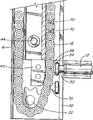
图2为一侧面剖视图,它示出一侧通道和用于保持杆的容器,连接链节在开口的上方处于贮存的位置;Figure 2 is a side sectional view showing the side channel and the container for holding the rod with the connecting link in the storage position above the opening;
图3为一侧面剖视图,它示出一侧通道和用于保持杆的容器,连接链节在开口的下方处于贮存的位置;Figure 3 is a side sectional view showing the side channel and the container for holding the rod with the connecting link in the storage position below the opening;
图4为细部的正视图,它示出用于与杆的端部接合的驱动链和链轮;Figure 4 is a front view of a detail showing the drive chain and sprocket for engagement with the end of the rod;
图5为细部的俯视剖面图,它示出一驱动链,它在一通道导轨中与一跨越一开口的杆连接;Figure 5 is a top sectional view of a detail showing a drive chain connected in a channel guide with a rod spanning an opening;
图6为一细部的正视剖面图,它示出杆与驱动链之间的连接的另一实施例;Figure 6 is a detail front sectional view showing another embodiment of the connection between the rod and the drive chain;
图7为一细部的侧视剖面图,它示出杆与驱动链之间的连接的又一实施例;Figure 7 is a side sectional view of a detail showing another embodiment of the connection between the rod and the drive chain;
图8为一透视图,它示出连至侧通道的杆,有一上部容器,用于在开口的上方贮存升起的杆;Figure 8 is a perspective view showing the rod connected to the side channel with an upper container for storing the rod raised above the opening;
图9为细部的立面正视图,它示出连至链节上并在开口的上方贮存在一容器中的杆的端部;Figure 9 is a detail elevational front view showing the end of the rod attached to the chain link and stored in a container above the opening;
图10为细部的俯视剖面图,它示出一擒纵机构,该机构用于保证杆从上容器中与驱动链上的隔开一定数量的链节的链节接合;Figure 10 is a top sectional view of a detail showing an escapement mechanism for securing the engagement of the lever from the upper container with the links of the drive chain spaced a certain number of links;
图11为端视图,它示出在开口的上方的容器,它具有杆和用于在开口的两侧将杆送入驱动链的相对的链节中的擒纵机构;Figure 11 is an end view showing the container above the opening with a rod and escapement for feeding the rod into opposing links of the drive chain on either side of the opening;
图12为一立面正视图,它示出安全杆组件的另一实施例,在相邻的杆间有柔性的连接间距器;Figure 12 is an elevational elevational view showing another embodiment of a safety bar assembly having flexible connecting spacers between adjacent bars;
图13为透视图,它示出带式柔性连接间距器;Figure 13 is a perspective view showing a belt-type flexible connection spacer;
图14为透视图,它示出缆式柔性连接间距器;Figure 14 is a perspective view showing a cable-type flexible connection spacer;
图15为侧面剖视图,它示出用于保留杆的直线式容器;Figure 15 is a side sectional view showing a linear container for retaining rods;
图16为侧面剖视图,它示出用于保留杆的非直线式容器;Figure 16 is a side sectional view showing a non-linear container for retaining rods;
图17为一侧视图,它示出一杆驱动链和一贮存驱动链,杆按照本发明的另一实施例互相隔开;Figure 17 is a side view showing a rod drive chain and a storage drive chain with the rods spaced from each other according to another embodiment of the present invention;
图18为与图17相似的侧视图,它示出两根杆在贮存驱动链上紧挨在一起;Figure 18 is a side view similar to Figure 17 showing the two rods close together on the storage drive chain;
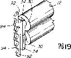
图19为一透视图,它示出两个具有长的搭接的固定器的杆,而且两杆紧挨在一起;Figure 19 is a perspective view showing two bars with long overlapping anchors, and the two bars are close together;
图20为一示意的透视图,它示出按照本发明的一个实施例的用于贮存驱动链的间歇式驱动机构;Figure 20 is a schematic perspective view showing an intermittent drive mechanism for storing drive chains according to one embodiment of the present invention;
图21为一局部立面正视图,它示出本发明的又一实施例,其中,各杆成一角度跨越开口;Figure 21 is a partial elevational front view showing a further embodiment of the invention wherein the bars span the opening at an angle;
图22为一细部的正视剖面图,它示出一不是无端的驱动链,并且在开口的上方贮存各杆之间的空闲的链节;Figure 22 is a detailed front sectional view showing a drive chain that is not endless and stores free links between the bars above the opening;
图23为一平面图,它示出将杆从驱动链上转移至贮存驱动链上的杆转移机构;Figure 23 is a plan view showing the rod transfer mechanism transferring rods from the drive chain to the storage drive chain;
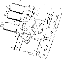
图24为一在图23中所示的杆转移机构的等轴图,它示出驱动链和贮存驱动链的将链轮和链条局部切去的分解图;FIG. 24 is an isometric view of the rod transfer mechanism shown in FIG. 23 showing an exploded view of the drive chain and storage drive chain with sprockets and chain partially cut away;
图25为一平面图,它示出用于转移杆的转移机构的另一实施例;Fig. 25 is a plan view, and it shows another embodiment of the transfer mechanism that is used for transfer bar;
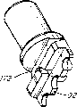
图26为一等轴图,它示出杆端的顶部,该杆端有一长的用于与一链条接合的固定器和一用于与杆转移机构的进给销接合的进给槽;Figure 26 is an isometric view showing the top of the rod end with a long retainer for engaging a chain and a feed slot for engaging the feed pin of the rod transfer mechanism;
图27为图26的杆端的俯视平面图;Figure 27 is a top plan view of the rod end of Figure 26;
图28为一等轴图,它示出图26和27的杆端的底部,示出杆端的底部上的进给槽在结构上与杆端的顶部的差别;Figure 28 is an isometric view showing the bottom of the rod end of Figures 26 and 27 showing the difference in structure between the feed slot on the bottom of the rod end and the top of the rod end;
图29为图26、27和28的杆端的底部平面图;Figure 29 is a bottom plan view of the rod end of Figures 26, 27 and 28;
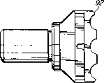
图30为另一杆转移机构的等轴图,它示出具有曲线形外缘的链节,其中,某些链节包括用于与杆端上的销接合的凹座;Figure 30 is an isometric view of another rod transfer mechanism showing links with curved outer edges, wherein some of the links include recesses for engagement with pins on rod ends;
图31示出一杆端的另一实施例,该杆端有单独的销;Figure 31 shows another embodiment of a rod end with a separate pin;
图32示出杆转移机构的一部分的另一实施例,该机构在链的驱动链轮的每侧有两个板,每个板有一用于将杆端进给至链条上的凹座。Figure 32 shows another embodiment of a portion of a rod transfer mechanism having two plates on each side of the chain's drive sprocket, each plate having a recess for feeding the rod end onto the chain.
在图1中示出一具有许多杆12的安全杆组件10,各杆用介于相邻的杆12之间的连接杆14隔开。用于两相邻的杆12的连接杆14介于连至两相邻的杆12的上方和下方的杆上的连接杆14之间。每根杆12的端部插入有一驱动链18的通道16中,该驱动链在一第一链轮20和一第二链轮22上移动。In FIG. 1 a safety bar assembly 10 is shown having a plurality of
图2示出位于一墙壁26的开口24的前面的安全杆组件的剖面。在开口24的上方示出一贮存区如一容器28,并且在容器28中示出具有连接杆14的折叠的安全杆12。图3示出与图2的安全杆组件相似的剖视图,其差别为,容器在开口的下方。FIG. 2 shows a cross-section of a safety bar assembly positioned in front of an opening 24 in a
在图4中示出了绕第二链轮22旋转的驱动链18的细节,该链轮有一从墙壁伸出并基本垂直于杆12的旋转轴线。每根杆12在每一端有一突起30。该突起穿过通道16的侧面中的侧槽32。突起30有一将杆12的端部保持在通道16中的盘形构件34,并有一端部件36,该端部件向外伸,正好配合在驱动链18的链节38的口中。在下通道构件42中的链的导向40的作用为将驱动链18从链轮22推开,以使每根杆12的端部件36不致与链轮22的齿发生干涉。通道16用螺钉44和一图5所示的在通道16的外面延伸的弹夹盖46固定在壁上,在开口24的旁边;由于通道16优先放在建筑物的里面,故盖子46只能从里面够得着。In FIG. 4 there is shown a detail of the
在图6中示出一多齿连接,其中,在杆12的突起30上的盘形构件34有两个端部件36,它们以准确的距离隔开,以致它们在相邻的链节38之间在相邻的口中接合。两个端部件36防止杆12旋转。A multi-tooth connection is shown in FIG. 6, wherein the
图4、5和6示出了驱动链18,其链轮轴线基本与杆12成直角,而图7则示出另一实施例,其中,链轮轴线与杆12基本平行。示出一改进的链节板38A,它具有与驱动链18隔开一段距离的接合槽39。杆12的端部件36配合在接合槽39中并把持杆12,宛如杆按图4、5和6所示的方式被夹持在链节中。驱动链18和链轮20、22于是转过90°,以使通道16可以放置在开口的侧面。FIGS. 4 , 5 and 6 show a
图1示出了杆12之间的连接杆14,而图8则为一透视图,它示出一具有杆12但没有将杆12连在一起的连接杆的安全杆组件。这是可能的,因为开口不太宽,并且杆12不容易被撬开。图9、10和11示出用于图8所示的卷帘门组件的机构。驱动链18如图9所示在第一链轮20上旋转,该链轮为一个八个齿的驱动链轮,去掉一个齿。每次第一链轮20旋转而去掉的齿空着,每根杆12的突起30上的端部件36与链节38的连接口接合,然后在驱动链18绕链轮20移动时跨越开口被输送。链轮20上的去掉的齿在图10中表示得更清楚,端部件36与驱动链18的链节38接合。第一链轮20在轴48上旋转,该轴又由一从动的锥齿轮50驱动。一驱动轴52跨越开口在两根驱动链18之间延伸。虽然未示出,但驱动轴52由一齿轮电动机驱动,该齿轮电动机可沿任一方向转动,以使杆12跨越开口滑动。在驱动轴的每一端有一驱动锥齿轮54,它与轴48上的从动锥齿轮50啮合,以驱动第一链轮20。这样,驱动轴52的旋转同时转动在开口的每一侧的通道16中的第一链轮20,并以完全相同的速度移动链条18,以使各杆12在它们与驱动链18的各自的链节接合时保持基本均匀地隔开。Figure 1 shows the connecting
在驱动锥齿轮54上固定一擒纵轮54,它有一缺口58与杆12的突起30接合。各杆12最初贮存在一贮存结构中,该结构在所示实施例中为一在开口上方并位于横轴52的上方的容器28。一导向条60将杆12导入槽62中,在该处各杆分别下落。当擒纵轮56旋转时,第一杆12的突起30被缺口58接合,该缺口向下移动杆12,直至杆12的端部件36与链节38的连接口接合,该链节位于链轮20上,其位置为去掉一个齿的地方。这适用于在开口的每一侧的两个驱动链18的两个链轮20。当驱动链18向下移动时,杆12的突起30配合在通道16的槽32中。擒纵轮56继续旋转,直至它拾取第二杆12并将其下降至通道16的槽32中,同时,杆12的每个端部件36在链轮20的去掉一个齿的地方与链节的连接口配合。如此继续,直至所有杆12都跨越开口24互相隔开。对于一个八个齿的链轮20,端部件36将每隔七个链节接合。在一个实施例中,一个去掉一个齿的八个齿的链轮提供杆的4英寸的间距。在另一实施例中,驱动链的上下速度都是2英寸每秒。On the driving
当上升杆时,驱动链沿与擒纵轮56相反的方向移动。擒纵轮56中的缺口58拾取每根杆12的突起30,并使端部件36与驱动链18脱开。杆12被上升并被推入容器28中,该容器将其它杆往上推。容器28最好衬以软质材料,以减少杆12的噪声。当杆12向上移动时,它们铺开,占据容器28的空间。When the lever is raised, the drive chain moves in the opposite direction to the
图9、10和11所示的机构所示的容器28在开口的顶部,而在另一实施例中,容器28可以放置在开口的下方。与所示相同的机构可以用于进给单个的水平杆12,使之与链条18接合。不过,设置一弹簧机构(未示出),以向上推每个水平的杆12,以保证每个突起30与擒纵轮56的缺口58接合。The mechanisms shown in Figures 9, 10 and 11 show the
在其它实施例中,安全杆组件可以有基本垂直的杆12,而通道16和驱动链18则在顶部和底部。在此结构中,杆12与驱动链18的接合并不依赖重力。In other embodiments, the safety bar assembly may have a substantially
当连接杆14将各杆连在一起时,擒纵轮并不重要,只要第一杆12总是保持在驱动链18的一个链节38中。去掉一个齿的链齿只允许杆12的端部件36在去掉一个链轮齿的地方接合。采用图4所示的机构,一链的导向40将驱动链18从链轮20、22上推出,以致链轮齿不与和驱动链18的链节38接合的杆12的端部件36发生干涉。在此机构中设置其它间距结构。在一实施例中,如图4所示的塞子70位于链节38的每个所谓的连接口或空间中。塞子70最好用塑料制造并与链节38一起移动,从而防止杆12的端部件36与链节38接合。通过沿驱动链将塞子70互相隔开预定数目的链节,杆12就按预定的距离互相隔开,因为它们不能在放置塞子的地方与链节38接合。As the connecting
图12中示出保持隔开一预定的距离的另一实施例。在此实施例中,用于保持杆12的容器28位于开口的下方,在第二链轮22的下面。Another embodiment where a predetermined distance is maintained is shown in FIG. 12 . In this embodiment, the
链轮22为一短齿链轮,也就是说,齿22A的顶部去掉的链轮。通过截短的齿,杆12的端部件36不会与齿22A发生干涉。
此实施例中示出短齿链轮,但是可以采用如图9所示的具有去掉一个齿的链轮,或按另一种方案,如图4所示,可以采用链的导向40,以将链条从链轮上移开。In this embodiment a short-toothed sprocket is shown, but a sprocket with one tooth removed as shown in Figure 9 could be used, or alternatively, as shown in Figure 4, a
示出一柔性连接间距器80,它在杆12的每一端固定在突起30上。间距器在杆跨越开口时确定了各杆12之间的预定的距离,但是在杆跨越开口移入容器28中时,如图12所示折叠,以使各杆能彼此紧挨在一起。当永远不与驱动链18脱开的第一杆12向上移动时,间距器80拉曳在其后面的相邻的杆,使其与驱动链18的链节接合。A
如图13所示,柔性连接间距器80为一具有孔82的带子,该孔在杆12的端部配合在突起30上。在另一实施例中,具有预定长度的单独的带固定在相邻的杆12之间。在图14中,柔性连接间距器80为一缆,而且在杆12的端部穿过突起30中的孔84配合。穿过端部件36的紧定螺钉夹86固定缆式间距器80,以保持杆12之间的距离。图15示出的容器28的形状做成使杆12成直线地位于其中。图16示出的容器28的形状做成使杆非直线地放置。容器28如图12所示位于开口的下方。As shown in FIG. 13 , the
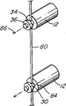
在图17、18和19中示出另一实施例,它有第二套称为贮存驱动链90的驱动链。贮存驱动链90的位置与杆驱动链18成一直线,与位于开口的上方的第一链轮20相邻,或与在开口的下方的第二链轮22相邻。在所示的实施例中,链轮全部都是如图12所示的短齿链轮,以使链轮齿不与驱动链和杆12之间的接头发生干涉。杆12在每一端都有突起30,以如图5所示配合在通道16的侧槽32中。在突起的端部的盘形构件34有长的固定器92,它有四个成一直线的突起94,以与相邻的链节的口接合。如图19所示,固定器92有一小于链节的链板之间的间距的一半宽度的宽度,而且固定器布置成搭接,以使相邻的杆12有错开的固定器,以使各杆在容器28中可以保持在一起。Another embodiment is shown in FIGS. 17, 18 and 19 which has a second set of drive chains called
在图17中,所示杆12互相隔开,第一杆具有固定器92,固定器跨接在杆驱动链18与贮存驱动链90之间。当杆12被移动,以便贮存时,杆驱动链18移动固定器18,以使它与贮存驱动链90接合,此链被间歇地驱动,并移动至正好足以使顶上的驱动器92排空杆驱动链18。以后,如图18所示,将下一根杆12向上移动,而下面的杆的固定器92则与第一杆的固定器搭接,以使两根杆12紧挨在一起。这样,当各杆被贮存时,它们全部一起紧挨在贮存驱动链90上。In FIG. 17 , the
为了下降或上升杆12,根据贮存驱动链90是位于开口的上方还是下方,贮存驱动链90间歇地移动,进给各杆,以使固定器92与连续移动的杆驱动链18接合。贮存驱动链90的间歇性移动布置成保证跨越开口的各杆之间的间距也就是链节数总是相同的。To lower or raise the
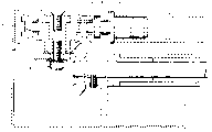
图20为用于图17和18所示的杆驱动链18和贮存驱动链的驱动机构的示意透视图。一中间齿轮100与一连续驱动齿轮102啮合,以驱动杆驱动链的第一或第二链轮20、22。一间歇驱动齿轮段104与中间齿轮100一体地形成,并驱动一间歇驱动齿轮106,该间歇驱动齿轮106驱动贮存驱动链90。一间歇锁紧轮108用键与中间齿轮100连接,并有一切口110,该切口位于间歇驱动齿轮段104的上方。一锁紧块112固定在间歇驱动齿轮106上并在间歇驱动齿轮段104与间歇驱动齿轮106啮合时,只允许间歇驱动齿轮106旋转。在所有的其它时间,间歇齿轮锁紧块112则不能旋转,因为它被锁紧轮108的周边阻止。FIG. 20 is a schematic perspective view of the drive mechanism for the
所描述的驱动机构可以是一个用于转动驱动轴52的齿轮驱动电动机。在一优选的实施例中,包括一与电动机一起的制动器,以使当动力切断时,杆12不能移动。在另一实施例中,可以设置一互相旋转的曲柄臂(未示出),以使一旦有动力故障时,杆12可以简单地通过转动驱动轴52而下降或上升。The drive mechanism depicted may be a gear drive motor for rotating the
此外,对于紧急情况,可以在齿轮驱动电动机与驱动轴52之间包括一离合器或切断销,以使齿轮电动机与驱动轴50脱开。这允许杆12能被向上或向下推,因为驱动链可自由移动。驱动链18在链轮20、22上旋转,并且在每根水平杆到达驱动链18的端部时,杆与驱动链18脱开,并且或是落在地面上或是按另一种方案,落入一容器中,这要取决于所提供的特殊的实施例而定,这样,就提供一用于紧急情况的出口。安全杆组件最好放在建筑物里面,因为入侵者不容易够着操作机构。Additionally, a clutch or disconnect pin may be included between the gear drive motor and the
图23至29示出用于在驱动链18和贮存链90之间转移杆12的转移机构的另一实施例。在所示的实施例中,设置转移臂130,连同一转移臂销132,该销在操作中按一用虚线134表示的旋转路径移动。旋转臂销132如图26至29所示与一杆端接合,以便将杆12从驱动链18转移至贮存驱动链90上。转移臂销132沿路径134的移动由一机构来动作,该机构包括转移臂130、杠杆臂136和升举臂138。杠杆臂136在杠杆臂安装座162处可摆动地连至背板160上,并在臂接点164处可摆动地连至转移臂130上。升举臂138通过升举臂座66可摆动地连至背板160上。臂130、136和138本身又被凸轮140致动。凸轮140上的外槽142容纳设置在杠杆臂136上的杠杆臂销146,以使凸轮140的旋转在杠杆臂销146在外槽142中行走时移动杠杆臂136。同样,内槽144容纳设置在升举臂138上的升举臂销148,以使凸轮140的旋转在杠杆臂销148在内槽144中行走时移动升举臂138。升举臂138的移动通过使销150致动而连通,以转动臂130,该销150在升举臂槽152中行走。凸轮140经由图23中用虚线表示的转移齿轮156由驱动齿轮154驱动。凸轮140可用于驱动贮存驱动链90,而驱动轮齿轮154则可如图24所示用于驱动驱动链18,该图用分解图示出驱动链轮168和贮存链轮170。23 to 29 show another embodiment of a transfer mechanism for transferring
图26至29示出具有长的固定器92的杆端,该固定器用于与驱动链18和贮存链90接合。作为图17和18的链转移机构的替代方案,图26至29的杆端用于与图23至25的链转移机构一起使用。为了与转移臂销132接合,杆端做有一顶部进给槽172和一底部进给槽174,它们的每一个用于被转移杆臂销132接合,以沿任何方向在贮存驱动链90与杆驱动链18之间运载杆12。26 to 29 show the rod end with a
图30示出驱动链18的链节的另一种构形,其中,每个链节的侧板182有一向外凸的弓形,它在驱动链18绕驱动链轮168移动时提供一平滑的曲线形外表面。在这种实施例中,可设置断续的链节,其中,侧板182做有凹座184,该凹座用于接纳杆端上的侧销180。在操作中,当驱动链18绕驱动链轮168行走,并且杆12堆垛在驱动链轮168的上方时,杆12将在凹座184可用于接纳侧销时周期性地被允许与驱动链18接合。侧销180可以旋转,以有利于靠在侧板182上移动。同样,通道销181可以旋转,以有利于在通道16中移动。Figure 30 shows another configuration of the links of the
在另一实施例中,如同在图32中所示的例子那样,在驱动链轮168的旁边可以设置一个或更多的圆形的可旋转的凸轮盘,其中,凸轮盘188有一与凹座184类似的凹座,以使凸轮盘188按与侧板182相同的方式起作用,以得到同样的结果,即允许杆12与驱动链18接合(与图11所示的擒纵轮56中的缺口58的功能多少有些类似)。凹座184或凸轮盘188中的凹座200的几何形状可以变化,以有利于处理侧销180。在另一实施例中,如图31所示,一单独的杆端销186可以同时按与侧销180和通道销181相似的方式起作用。In another embodiment, as in the example shown in FIG. 32, one or more circular rotatable cam discs may be provided beside the
图21示出一安全杆组件,其中,杆12的端部用一可摆动的滑动的杆固定装置120连在一起,该固定装置可以有单个的如图4所示的用于连至链节38上的销组件,或如图6所示的多个连接。这允许杆12能按之字形跨越开口。Figure 21 shows a safety bar assembly in which the ends of the
虽然在其它图中所示的驱动链18是按绕第一链轮20和第二链轮22旋转示出的,但是在图22中示出一不是无端的驱动链18A。一单个的驱动链轮20A位于通道16的顶部,而驱动链18A则使杆的端部件34永久地固定在按预定数目的链节隔开的链节38上。链轮20A为一短齿链轮,以致其齿不与杆的端部件36发生干涉。当杆12向上移入贮存区28中时,驱动链18A的中间链节如图所示折叠起来,以致各杆贮存成尽可能靠近。链轮20A向下拉驱动链18A,跨越开口进给杆12,并在各杆12之间提供间距。While
安全杆组件也可以设置布置。布置可以例如通过卷在一用弹簧致动的轴上而收缩,罩的端部用于例如通过钩子连至安全杆组件的末端部分上。另一种方案为,布可以设置在杆12的里面或围绕杆。例如,杆可以穿过布中的小袋,以使布提供一不允许人家看穿安全杆组件的帘子。A safety bar assembly may also be arranged. The arrangement may be retracted, for example by rolling on a spring actuated shaft, the end of the shroud being adapted to attach, for example by hook, to the end portion of the safety bar assembly. Alternatively, the cloth could be placed inside or around the
可以对此处所示的实施例作出各种更改而不脱离本发明的仅仅由下列权利要求书限制的范围。Various changes may be made to the embodiments shown here without departing from the scope of the invention, which is limited only by the following claims.
Claims (32)
Applications Claiming Priority (2)
| Application Number | Priority Date | Filing Date | Title |
|---|---|---|---|
| US09/524,089 | 2000-03-13 | ||
| US09/524,089 US6394167B1 (en) | 1997-03-20 | 2000-03-13 | Security bar assembly |
Publications (2)
| Publication Number | Publication Date |
|---|---|
| CN1418282A CN1418282A (en) | 2003-05-14 |
| CN1179110C true CN1179110C (en) | 2004-12-08 |
Family
ID=24087717
Family Applications (1)
| Application Number | Title | Priority Date | Filing Date |
|---|---|---|---|
| CNB018064663A Expired - Fee Related CN1179110C (en) | 2000-03-13 | 2001-03-13 | Safety Bar Transfer Mechanism Components |
Country Status (21)
| Country | Link |
|---|---|
| US (3) | US6394167B1 (en) |
| EP (1) | EP1264064A1 (en) |
| JP (1) | JP2003527512A (en) |
| KR (2) | KR20070090272A (en) |
| CN (1) | CN1179110C (en) |
| AU (2) | AU2001242147C1 (en) |
| BR (1) | BR0109240A (en) |
| CA (1) | CA2402381A1 (en) |
| CU (1) | CU23130A3 (en) |
| EA (1) | EA004388B1 (en) |
| HK (1) | HK1054257B (en) |
| HU (1) | HUP0300307A2 (en) |
| IL (2) | IL151668A0 (en) |
| MA (1) | MA25884A1 (en) |
| MX (1) | MXPA02008964A (en) |
| NO (1) | NO20024360L (en) |
| NZ (1) | NZ521385A (en) |
| PL (1) | PL358129A1 (en) |
| UA (1) | UA74361C2 (en) |
| WO (1) | WO2001069029A1 (en) |
| ZA (1) | ZA200207271B (en) |
Families Citing this family (9)
| Publication number | Priority date | Publication date | Assignee | Title |
|---|---|---|---|---|
| US6394167B1 (en) * | 1997-03-20 | 2002-05-28 | Moshe Cohen-Ravid | Security bar assembly |
| US7429245B2 (en) | 2003-07-14 | 2008-09-30 | Welch Allyn, Inc. | Motion management in a fast blood pressure measurement device |
| US8468751B2 (en) * | 2011-05-13 | 2013-06-25 | Hufcor, Inc. | Method of stowing and deploying wall panels |
| NL2012620C2 (en) | 2014-01-31 | 2015-08-06 | Stackdoor B V | Security grille and security grille system. |
| NL2016133B1 (en) | 2016-01-21 | 2017-07-25 | Stackdoor B V | Collapsible security grille, grille system, bar, and method. |
| US10465383B2 (en) * | 2017-01-23 | 2019-11-05 | Advanced Equipment Corporation | Panel storage system and devices |
| IT201800007023A1 (en) * | 2018-07-09 | 2020-01-09 | Motorized protection barrier | |
| KR102502694B1 (en) * | 2020-07-21 | 2023-02-23 | 주식회사 에스케이디 하이테크 | Safety equipment of train platform |
| US20240060295A1 (en) * | 2022-08-17 | 2024-02-22 | A&C Future, Inc. | Collapsible Prefabricated Mechanical Soft Wall |
Family Cites Families (43)
| Publication number | Priority date | Publication date | Assignee | Title |
|---|---|---|---|---|
| US343956A (en) | 1886-06-15 | holmes | ||
| US813631A (en) | 1904-12-12 | 1906-02-27 | Victor Elmquist | Door for grain-cars. |
| FR506153A (en) | 1919-11-17 | 1920-08-16 | Richard Gossow | Advanced grid |
| US1597392A (en) | 1925-01-28 | 1926-08-24 | Rorabeck Malcolm | Grain-car door |
| US2057850A (en) | 1934-03-14 | 1936-10-20 | Sims Oscar | Closure device |
| US2095690A (en) | 1936-01-08 | 1937-10-12 | Gen Door Company | Rolling door structure |
| CH258795A (en) | 1945-01-04 | 1948-12-31 | Buret Albert | Berry closing device. |
| US2423987A (en) | 1945-09-17 | 1947-07-15 | Levikow Simon | Frame and closure therefor |
| DE866843C (en) | 1951-01-28 | 1953-02-12 | Karl-Heinz Kalinowsky | Protective grille for shop window |
| US2672192A (en) | 1951-11-02 | 1954-03-16 | Goldner Richard | Shutter or the like and slats therefor |
| US2882045A (en) | 1956-03-12 | 1959-04-14 | A E Moore Company Inc | Control mechanism and circuit for garage doors and the like |
| US3103246A (en) | 1961-03-13 | 1963-09-10 | Panel Lift Door Corp | Panel door with screw drive means |
| US3289350A (en) | 1964-07-07 | 1966-12-06 | Warren E Moody | Garage door operators |
| US3389740A (en) | 1966-02-07 | 1968-06-25 | Allan Moyer Buehler | Door operators |
| US3601175A (en) | 1969-08-18 | 1971-08-24 | Cookson Co | Articulated grille |
| US3738413A (en) | 1971-07-01 | 1973-06-12 | R Frobosilo | Retractable barrier |
| US3739832A (en) | 1972-01-10 | 1973-06-19 | Celotex Corp | Overhead grille |
| US3955661A (en) | 1972-06-28 | 1976-05-11 | Lsb Industries, Inc. | Apparatus for opening and closing door members and the like |
| US3842891A (en) | 1973-08-27 | 1974-10-22 | S Kinnroth | Shutter-blind device |
| US3850465A (en) | 1973-11-19 | 1974-11-26 | Cookson Co | Self-acting lock for articulated, rolling grilles |
| US4139042A (en) * | 1976-12-13 | 1979-02-13 | Japan New Plate Hokusho Industrial Co. Ltd. | Shutter device |
| US4282920A (en) | 1979-06-25 | 1981-08-11 | Jim Walter Doors North American, Div. Of The Celotex Corp. | Grille |
| US4379478A (en) | 1980-06-09 | 1983-04-12 | Dale Lichy | Folding overhead doors |
| DE3249091C2 (en) * | 1981-10-05 | 1993-02-25 | Sanwa Shutter Corp | Pull-up blinds |
| IT1187106B (en) | 1985-12-03 | 1987-12-16 | Quinto Giovanetti | ANTI-THEFT SECURITY CONVENTION APPLICABLE TO THE PROFILES COMPONENT OF THE ROLLING SHUTTERS OR ROLLING SHUTTERS FOR WINDOWS AND DOORS |
| US4838331A (en) * | 1986-10-06 | 1989-06-13 | Bunka Shutter Co., Ltd. | Slat opening/closing drive mechanism in shutter equipment |
| SE459873B (en) | 1986-10-09 | 1989-08-14 | Nomafa Ab | SAFETY DEVICE, IN PARTICULAR, FOR S ROLLPORTS |
| FR2653160B1 (en) | 1989-10-18 | 1992-01-17 | Simu | GENDER CLOSURE WINDING DEVICE WITH LOGE DRIVE MECHANISM IN THE MANOEUVER DRUM. |
| AU633710B2 (en) * | 1990-04-02 | 1993-02-04 | Sanwa Shutter Corporation | Panel shutter device |
| JP2918630B2 (en) * | 1990-06-05 | 1999-07-12 | 文化シヤツター株式会社 | Panel shutter device |
| US5373887A (en) | 1991-04-17 | 1994-12-20 | Glover; Thomas H. C. | Security gate |
| US5139075A (en) | 1991-05-31 | 1992-08-18 | Eddy Desrochers | Operator for a rolling door assembly |
| US5211440A (en) | 1991-12-13 | 1993-05-18 | Cramaro Tarpeulin Systems, Inc. | Safety mechanism for vehicle tarpaulin system |
| US5222403A (en) | 1992-04-01 | 1993-06-29 | Gmi Holdings, Inc. | Drive mechanism engaging means for garage door operator |
| US5469905A (en) | 1993-09-07 | 1995-11-28 | Fold-A-Shield | Security and hurricane shutter |
| IT1265956B1 (en) | 1993-11-08 | 1996-12-16 | Quinto Giovanetti | MOBILE WINDOW FOR WINDOWS COMBINED WITH ROLLING SHUTTERS |
| IT1280449B1 (en) | 1995-07-28 | 1998-01-20 | L I M Di Ildebrando Zurlo | RETRACTABLE PACKAGE SAFETY WINDOW. |
| FR2747152B1 (en) | 1996-04-03 | 1999-11-19 | Correard Jean Luc Laurent Aime | MONITORING AND ANTI-CRUSHING SYSTEM FOR VERTICALLY MOVED BUILDINGS |
| US6035917A (en) * | 1997-03-20 | 2000-03-14 | Ravco Innovations, Inc. | Foldable security bar assembly |
| US6394167B1 (en) * | 1997-03-20 | 2002-05-28 | Moshe Cohen-Ravid | Security bar assembly |
| US5957181A (en) * | 1997-03-20 | 1999-09-28 | Ravco Innovations, Inc. | Security bar assembly |
| HU1808U (en) | 1999-12-22 | 2000-07-28 | Gabriella Sapi | Moving structure for foldable safety grille |
| HU1941U (en) | 2000-02-09 | 2001-01-29 | Horvath Dr Tamas | Constitute point of junction unit for pole and tubular frame structure |
-
2000
- 2000-03-13 US US09/524,089 patent/US6394167B1/en not_active Expired - Fee Related
-
2001
- 2001-03-13 IL IL15166801A patent/IL151668A0/en active IP Right Grant
- 2001-03-13 MX MXPA02008964A patent/MXPA02008964A/en active IP Right Grant
- 2001-03-13 CA CA002402381A patent/CA2402381A1/en not_active Abandoned
- 2001-03-13 AU AU2001242147A patent/AU2001242147C1/en not_active Ceased
- 2001-03-13 BR BR0109240-5A patent/BR0109240A/en not_active Application Discontinuation
- 2001-03-13 CN CNB018064663A patent/CN1179110C/en not_active Expired - Fee Related
- 2001-03-13 UA UA2002097426A patent/UA74361C2/en unknown
- 2001-03-13 KR KR1020077018177A patent/KR20070090272A/en not_active Abandoned
- 2001-03-13 EP EP01914876A patent/EP1264064A1/en not_active Withdrawn
- 2001-03-13 HK HK03106485.6A patent/HK1054257B/en not_active IP Right Cessation
- 2001-03-13 NZ NZ521385A patent/NZ521385A/en unknown
- 2001-03-13 PL PL01358129A patent/PL358129A1/en not_active Application Discontinuation
- 2001-03-13 EA EA200200946A patent/EA004388B1/en unknown
- 2001-03-13 WO PCT/CA2001/000330 patent/WO2001069029A1/en not_active Ceased
- 2001-03-13 AU AU4214701A patent/AU4214701A/en active Pending
- 2001-03-13 US US10/221,512 patent/US6868891B2/en not_active Expired - Fee Related
- 2001-03-13 JP JP2001567890A patent/JP2003527512A/en active Pending
- 2001-03-13 HU HU0300307A patent/HUP0300307A2/en unknown
- 2001-03-13 KR KR1020027012081A patent/KR20030019322A/en not_active Abandoned
-
2002
- 2002-06-05 US US10/164,061 patent/US6886620B2/en not_active Expired - Fee Related
- 2002-09-09 MA MA26807A patent/MA25884A1/en unknown
- 2002-09-10 ZA ZA200207271A patent/ZA200207271B/en unknown
- 2002-09-10 IL IL151668A patent/IL151668A/en not_active IP Right Cessation
- 2002-09-12 CU CU196A patent/CU23130A3/en unknown
- 2002-09-12 NO NO20024360A patent/NO20024360L/en not_active Application Discontinuation
Also Published As
| Publication number | Publication date |
|---|---|
| EP1264064A1 (en) | 2002-12-11 |
| KR20070090272A (en) | 2007-09-05 |
| MA25884A1 (en) | 2003-10-01 |
| AU2001242147C1 (en) | 2006-04-27 |
| CN1418282A (en) | 2003-05-14 |
| CA2402381A1 (en) | 2001-09-20 |
| KR20030019322A (en) | 2003-03-06 |
| US6394167B1 (en) | 2002-05-28 |
| EA200200946A1 (en) | 2003-04-24 |
| EA004388B1 (en) | 2004-04-29 |
| US6886620B2 (en) | 2005-05-03 |
| AU4214701A (en) | 2001-09-24 |
| UA74361C2 (en) | 2005-12-15 |
| US20030019587A1 (en) | 2003-01-30 |
| HUP0300307A2 (en) | 2003-06-28 |
| AU2001242147B2 (en) | 2005-09-01 |
| HK1054257B (en) | 2005-09-16 |
| NZ521385A (en) | 2004-02-27 |
| IL151668A0 (en) | 2003-04-10 |
| JP2003527512A (en) | 2003-09-16 |
| ZA200207271B (en) | 2005-06-10 |
| US20030178152A1 (en) | 2003-09-25 |
| WO2001069029A1 (en) | 2001-09-20 |
| IL151668A (en) | 2007-07-24 |
| NO20024360L (en) | 2002-11-12 |
| MXPA02008964A (en) | 2004-10-15 |
| NO20024360D0 (en) | 2002-09-12 |
| PL358129A1 (en) | 2004-08-09 |
| CU23130A3 (en) | 2006-05-22 |
| US6868891B2 (en) | 2005-03-22 |
| BR0109240A (en) | 2002-12-24 |
| HK1054257A1 (en) | 2003-11-21 |
Similar Documents
| Publication | Publication Date | Title |
|---|---|---|
| CN1179110C (en) | Safety Bar Transfer Mechanism Components | |
| CN1140696C (en) | Security fence assembly for an opening and method of forming a security fence assembly in an opening | |
| JP2918630B2 (en) | Panel shutter device | |
| CN106460455B (en) | Systems such as venetian shutters, etc. housed in double glazing with enclosures that prevent the shutter from moving when transporting or assembling the system | |
| AU2001242147A1 (en) | Security bar transfer mechanism assembly | |
| EP0562711A2 (en) | Vertical louver blind | |
| AU2005203241B2 (en) | Security bar assembly | |
| CN1471608A (en) | Ring drive belt lock for safety barrier | |
| AU2005201135B2 (en) | Security bar assembly | |
| JPH0137092Y2 (en) | ||
| HK1024728B (en) | Security bar assembly | |
| CA2299479C (en) | Machine for conveying lumber or logs of wood | |
| EP1672164A2 (en) | Chain stopper | |
| RU2054115C1 (en) | Lightproof device | |
| CN112591604A (en) | Steel sheet fixing device is used in transportation | |
| JPH06137039A (en) | Louver type sliding door |
Legal Events
| Date | Code | Title | Description |
|---|---|---|---|
| C06 | Publication | ||
| PB01 | Publication | ||
| C10 | Entry into substantive examination | ||
| SE01 | Entry into force of request for substantive examination | ||
| C14 | Grant of patent or utility model | ||
| GR01 | Patent grant | ||
| C19 | Lapse of patent right due to non-payment of the annual fee | ||
| CF01 | Termination of patent right due to non-payment of annual fee |